EP3437245B1 - Verfahren und vorrichtung zur synchronisation für fahrzeug-zu-x-kommunikation - Google Patents
Verfahren und vorrichtung zur synchronisation für fahrzeug-zu-x-kommunikation Download PDFInfo
- Publication number
- EP3437245B1 EP3437245B1 EP17775911.5A EP17775911A EP3437245B1 EP 3437245 B1 EP3437245 B1 EP 3437245B1 EP 17775911 A EP17775911 A EP 17775911A EP 3437245 B1 EP3437245 B1 EP 3437245B1
- Authority
- EP
- European Patent Office
- Prior art keywords
- synchronization signal
- synchronization
- gnss
- enb
- sequence
- Prior art date
- Legal status (The legal status is an assumption and is not a legal conclusion. Google has not performed a legal analysis and makes no representation as to the accuracy of the status listed.)
- Active
Links
- 238000000034 method Methods 0.000 title claims description 39
- 238000004891 communication Methods 0.000 title description 48
- 238000013507 mapping Methods 0.000 claims description 50
- 230000001360 synchronised effect Effects 0.000 claims description 38
- 230000005540 biological transmission Effects 0.000 description 16
- 238000010586 diagram Methods 0.000 description 9
- 125000004122 cyclic group Chemical group 0.000 description 7
- 239000013256 coordination polymer Substances 0.000 description 4
- 235000008694 Humulus lupulus Nutrition 0.000 description 3
- 230000008054 signal transmission Effects 0.000 description 2
- 230000001419 dependent effect Effects 0.000 description 1
- 230000000694 effects Effects 0.000 description 1
- 238000005516 engineering process Methods 0.000 description 1
- 230000006870 function Effects 0.000 description 1
- 238000009827 uniform distribution Methods 0.000 description 1
Images


Classifications
-
- H—ELECTRICITY
- H04—ELECTRIC COMMUNICATION TECHNIQUE
- H04W—WIRELESS COMMUNICATION NETWORKS
- H04W56/00—Synchronisation arrangements
- H04W56/001—Synchronization between nodes
- H04W56/0015—Synchronization between nodes one node acting as a reference for the others
-
- G—PHYSICS
- G01—MEASURING; TESTING
- G01S—RADIO DIRECTION-FINDING; RADIO NAVIGATION; DETERMINING DISTANCE OR VELOCITY BY USE OF RADIO WAVES; LOCATING OR PRESENCE-DETECTING BY USE OF THE REFLECTION OR RERADIATION OF RADIO WAVES; ANALOGOUS ARRANGEMENTS USING OTHER WAVES
- G01S19/00—Satellite radio beacon positioning systems; Determining position, velocity or attitude using signals transmitted by such systems
- G01S19/01—Satellite radio beacon positioning systems transmitting time-stamped messages, e.g. GPS [Global Positioning System], GLONASS [Global Orbiting Navigation Satellite System] or GALILEO
- G01S19/13—Receivers
- G01S19/31—Acquisition or tracking of other signals for positioning
-
- H—ELECTRICITY
- H04—ELECTRIC COMMUNICATION TECHNIQUE
- H04B—TRANSMISSION
- H04B1/00—Details of transmission systems, not covered by a single one of groups H04B3/00 - H04B13/00; Details of transmission systems not characterised by the medium used for transmission
- H04B1/38—Transceivers, i.e. devices in which transmitter and receiver form a structural unit and in which at least one part is used for functions of transmitting and receiving
- H04B1/3822—Transceivers, i.e. devices in which transmitter and receiver form a structural unit and in which at least one part is used for functions of transmitting and receiving specially adapted for use in vehicles
-
- H—ELECTRICITY
- H04—ELECTRIC COMMUNICATION TECHNIQUE
- H04L—TRANSMISSION OF DIGITAL INFORMATION, e.g. TELEGRAPHIC COMMUNICATION
- H04L1/00—Arrangements for detecting or preventing errors in the information received
- H04L1/004—Arrangements for detecting or preventing errors in the information received by using forward error control
- H04L1/0056—Systems characterized by the type of code used
- H04L1/0071—Use of interleaving
-
- H—ELECTRICITY
- H04—ELECTRIC COMMUNICATION TECHNIQUE
- H04L—TRANSMISSION OF DIGITAL INFORMATION, e.g. TELEGRAPHIC COMMUNICATION
- H04L27/00—Modulated-carrier systems
- H04L27/26—Systems using multi-frequency codes
- H04L27/2601—Multicarrier modulation systems
- H04L27/2602—Signal structure
- H04L27/261—Details of reference signals
- H04L27/2613—Structure of the reference signals
-
- H—ELECTRICITY
- H04—ELECTRIC COMMUNICATION TECHNIQUE
- H04L—TRANSMISSION OF DIGITAL INFORMATION, e.g. TELEGRAPHIC COMMUNICATION
- H04L27/00—Modulated-carrier systems
- H04L27/26—Systems using multi-frequency codes
- H04L27/2601—Multicarrier modulation systems
- H04L27/2647—Arrangements specific to the receiver only
- H04L27/2655—Synchronisation arrangements
- H04L27/2689—Link with other circuits, i.e. special connections between synchronisation arrangements and other circuits for achieving synchronisation
- H04L27/2692—Link with other circuits, i.e. special connections between synchronisation arrangements and other circuits for achieving synchronisation with preamble design, i.e. with negotiation of the synchronisation sequence with transmitter or sequence linked to the algorithm used at the receiver
-
- H—ELECTRICITY
- H04—ELECTRIC COMMUNICATION TECHNIQUE
- H04L—TRANSMISSION OF DIGITAL INFORMATION, e.g. TELEGRAPHIC COMMUNICATION
- H04L5/00—Arrangements affording multiple use of the transmission path
- H04L5/0001—Arrangements for dividing the transmission path
- H04L5/0003—Two-dimensional division
- H04L5/0005—Time-frequency
- H04L5/0007—Time-frequency the frequencies being orthogonal, e.g. OFDM(A), DMT
- H04L5/001—Time-frequency the frequencies being orthogonal, e.g. OFDM(A), DMT the frequencies being arranged in component carriers
-
- H—ELECTRICITY
- H04—ELECTRIC COMMUNICATION TECHNIQUE
- H04L—TRANSMISSION OF DIGITAL INFORMATION, e.g. TELEGRAPHIC COMMUNICATION
- H04L5/00—Arrangements affording multiple use of the transmission path
- H04L5/003—Arrangements for allocating sub-channels of the transmission path
-
- H—ELECTRICITY
- H04—ELECTRIC COMMUNICATION TECHNIQUE
- H04L—TRANSMISSION OF DIGITAL INFORMATION, e.g. TELEGRAPHIC COMMUNICATION
- H04L5/00—Arrangements affording multiple use of the transmission path
- H04L5/003—Arrangements for allocating sub-channels of the transmission path
- H04L5/0048—Allocation of pilot signals, i.e. of signals known to the receiver
- H04L5/0051—Allocation of pilot signals, i.e. of signals known to the receiver of dedicated pilots, i.e. pilots destined for a single user or terminal
-
- H—ELECTRICITY
- H04—ELECTRIC COMMUNICATION TECHNIQUE
- H04L—TRANSMISSION OF DIGITAL INFORMATION, e.g. TELEGRAPHIC COMMUNICATION
- H04L5/00—Arrangements affording multiple use of the transmission path
- H04L5/003—Arrangements for allocating sub-channels of the transmission path
- H04L5/0053—Allocation of signaling, i.e. of overhead other than pilot signals
-
- H—ELECTRICITY
- H04—ELECTRIC COMMUNICATION TECHNIQUE
- H04L—TRANSMISSION OF DIGITAL INFORMATION, e.g. TELEGRAPHIC COMMUNICATION
- H04L5/00—Arrangements affording multiple use of the transmission path
- H04L5/003—Arrangements for allocating sub-channels of the transmission path
- H04L5/0058—Allocation criteria
- H04L5/0064—Rate requirement of the data, e.g. scalable bandwidth, data priority
-
- H—ELECTRICITY
- H04—ELECTRIC COMMUNICATION TECHNIQUE
- H04L—TRANSMISSION OF DIGITAL INFORMATION, e.g. TELEGRAPHIC COMMUNICATION
- H04L67/00—Network arrangements or protocols for supporting network services or applications
- H04L67/01—Protocols
- H04L67/12—Protocols specially adapted for proprietary or special-purpose networking environments, e.g. medical networks, sensor networks, networks in vehicles or remote metering networks
-
- H—ELECTRICITY
- H04—ELECTRIC COMMUNICATION TECHNIQUE
- H04L—TRANSMISSION OF DIGITAL INFORMATION, e.g. TELEGRAPHIC COMMUNICATION
- H04L7/00—Arrangements for synchronising receiver with transmitter
- H04L7/0079—Receiver details
- H04L7/0087—Preprocessing of received signal for synchronisation, e.g. by code conversion, pulse generation or edge detection
-
- H—ELECTRICITY
- H04—ELECTRIC COMMUNICATION TECHNIQUE
- H04L—TRANSMISSION OF DIGITAL INFORMATION, e.g. TELEGRAPHIC COMMUNICATION
- H04L7/00—Arrangements for synchronising receiver with transmitter
- H04L7/0091—Transmitter details
-
- H—ELECTRICITY
- H04—ELECTRIC COMMUNICATION TECHNIQUE
- H04L—TRANSMISSION OF DIGITAL INFORMATION, e.g. TELEGRAPHIC COMMUNICATION
- H04L7/00—Arrangements for synchronising receiver with transmitter
- H04L7/0095—Arrangements for synchronising receiver with transmitter with mechanical means
-
- H—ELECTRICITY
- H04—ELECTRIC COMMUNICATION TECHNIQUE
- H04W—WIRELESS COMMUNICATION NETWORKS
- H04W4/00—Services specially adapted for wireless communication networks; Facilities therefor
- H04W4/30—Services specially adapted for particular environments, situations or purposes
- H04W4/40—Services specially adapted for particular environments, situations or purposes for vehicles, e.g. vehicle-to-pedestrians [V2P]
-
- H—ELECTRICITY
- H04—ELECTRIC COMMUNICATION TECHNIQUE
- H04W—WIRELESS COMMUNICATION NETWORKS
- H04W56/00—Synchronisation arrangements
- H04W56/001—Synchronization between nodes
-
- H—ELECTRICITY
- H04—ELECTRIC COMMUNICATION TECHNIQUE
- H04W—WIRELESS COMMUNICATION NETWORKS
- H04W56/00—Synchronisation arrangements
- H04W56/001—Synchronization between nodes
- H04W56/0025—Synchronization between nodes synchronizing potentially movable access points
-
- H—ELECTRICITY
- H04—ELECTRIC COMMUNICATION TECHNIQUE
- H04L—TRANSMISSION OF DIGITAL INFORMATION, e.g. TELEGRAPHIC COMMUNICATION
- H04L27/00—Modulated-carrier systems
- H04L27/26—Systems using multi-frequency codes
- H04L27/2601—Multicarrier modulation systems
- H04L27/2626—Arrangements specific to the transmitter only
- H04L27/2627—Modulators
- H04L27/2634—Inverse fast Fourier transform [IFFT] or inverse discrete Fourier transform [IDFT] modulators in combination with other circuits for modulation
- H04L27/2636—Inverse fast Fourier transform [IFFT] or inverse discrete Fourier transform [IDFT] modulators in combination with other circuits for modulation with FFT or DFT modulators, e.g. standard single-carrier frequency-division multiple access [SC-FDMA] transmitter or DFT spread orthogonal frequency division multiplexing [DFT-SOFDM]
Definitions
- the present disclosure relates to wireless communication, and more particularly, to a synchronization method and apparatus in Vehicle to X (V2X) communication.
- V2X Vehicle to X
- Vehicle-to-X (V2X: vehicle-to-everything) communication refers to a communication scheme that exchanges or shares information, such as traffic conditions or the like through communication with roadway infrastructures and other vehicles during driving.
- V2X may include vehicle-to-vehicle (V2V) indicating LTE-based communication between vehicles, vehicle-to-pedestrian (V2P) indicating LTE-based communication between terminals carried by a vehicle and a person, and vehicle to-infrastructure/network (VZI/N) indicating LTE-based communication between a vehicle and a roadside unit/network.
- the roadside unit (RSU) may be a base station or a transportation infrastructure entity embodied by a fixed terminal. For example, it may be an entity that transmits a speed notification to a vehicle.
- V2X technology is associated with a V2X environment that performs synchronization according to a Global Navigation Satellite System (GNSS) or a device equivalent to GNSS (hereinafter GNSS-equivalent device), in addition to performing synchronization according to a time reference from an evolved Node B (eNB) or a User Equipment (UE).
- GNSS Global Navigation Satellite System
- eNB evolved Node B
- UE User Equipment
- the features of the preamble of independent claim 1 are known from US 2013/0229953 A1 .
- a base station in a heterogeneous network is configured to communicate with a plurality of base stations via a backhaul link and configured to communicate with a plurality of subscriber stations.
- the base station includes a transmit path configured to transmit data, reference signals, synchronization signals and control elements to at least one of the plurality of subscriber stations.
- the base station also includes processing circuitry configured to map primary synchronization signals (PSS) and secondary synchronization signals (SSS) onto each of a carrier of a first carrier type and a carrier of a second carrier type.
- PSS primary synchronization signals
- SSS secondary synchronization signals
- the PSS and SSS on the second carrier type are mapped onto different time locations than in the first carrier type.
- the PSS/SSS are mapped onto consecutive resource elements (REs) on each of the carrier of the first type and the carrier of the second type.
- the mapping of the sequence to resource elements depends on the frame structure.
- the user equipment shall not assume that the primary synchronization signal is transmitted on the same antenna port as any of the downlink reference signals.
- the UE shall not assume that any transmission instance of the primary synchronization signal is transmitted on the same antenna port, or ports, used for any other transmission instance of the primary synchronization signal.
- WO 2014/182493 A1 discloses a method for wireless communications by a base station, comprising acquiring synchronization with a network based on a first synchronization signal transmitted from a primary base station or a secondary base station; determining a synchronization stratum for the base station based on whether the base station acquired synchronization with the network from the primary base station or from the secondary base station; andtransmitting a second synchronization signal for one or more other base stations to use for acquiring synchronization with the network, wherein the transmitting is based, at least in part, on the determined synchronization stratum.
- US 2015/351059 A1 discloses a method for a first user equipment inside a coverage area of a base station conducting device-to-device communication with a second user equipment outside the coverage area in a wireless communication system.
- the method comprises the steps of: dividing into a plurality of candidate sections a specific time unit for the device-to-device communication; and transmitting a reference signal for obtaining synchronization to the second user equipment from one section from among the candidate sections, when a random number that is generated is bigger than or equal to a critical value corresponding to the inside of the coverage area, wherein the critical value corresponding to the inside of the coverage area is smaller than a critical value corresponding to the outside of the coverage area.
- V2X Vehicle-to-X
- UE User Equipment
- a V2X UE may effectively select synchronization by taking into consideration the priority of received synchronization signals.
- the V2X UE may effectively transmit a selected synchronization signal to another V2X UE.
- V2X Vehicle-to-X
- V2X refers to V2V, V2P, and V2I/N, which may be defined, in association with LTE communication, as provided below.
- Table 1 shows details. [Table 1] V2V - covering LTE-based communication between vehicles V2P - covering LTE-based communication between a vehicle and a device carried by an individual (e.g. handheld terminal carried by a pedestrian, cyclist, driver or passenger) V2I/N - covering LTE-based communication between a vehicle and a roadside unit/network - A roadside unit (RSU) is a stationary infrastructure entity supporting V2X applications that can exchange messages with other entities supporting V2X applications.
- RSU roadside unit
- RSU is a term frequently used in existing ITS specifications, and the reason for introducing the term in the 3GPP specifications is to make the documents easier to read for the ITS industry.
- RSU is a logical entity that combines V2X application logic with the functionality of an eNB (referred to as eNB-type RSU) or UE (referred to as UE-type RSU).
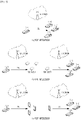
- FIGs. 1 , 2 , and 3 are diagrams illustrating a V2X scenario associated with the present disclosure.
- Table 2 and FIG. 1A through FIG. 1C illustrate a scenario that supports V2X operation based on only a PC5 interface.
- FIG. 1A illustrates a V2V operation.
- FIG. 1B illustrates a V2I operation.
- FIG. 1C illustrates a V2P operation.
- [Table 2] This scenario supports V2X operation only based on PC5.
- a UE transmits a V2X message to multiple UEs at a local area in sidelink.
- either transmitter UE or receiver UE(s) are UE-type RSU.
- - For V2P either transmitter UE or receiver UE(s) are pedestrian UE.
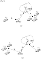
- Table 3 and FIGs. 2A through 2C illustrate a scenario that supports V2X operation based on only a Uu interface (i.e., an interface between a UE and an eNB).
- FIG. 2A illustrates a V2V operation.
- FIG. 2B illustrates a V2I operation.
- FIG. 2C illustrates a V2P operation. [Table 3] -
- This scenario supports V2X operation only based on Uu.
- ⁇ For V2V and V2P, a UE transmits a V2X message to E-UTRAN in uplink and E-UTRAN transmits it to multiple UEs at a local area in downlink.
- a UE when receiver is eNB type RSU, a UE transmits a V2I message to E-UTRAN(eNB type RSU) in uplink; when transmitter is eNB type RSU, E-UTRAN(eNB type RSU) transmits a I2V message to multiple UEs at a local area in downlink.
- E-UTRAN For V2P, either transmitter UE or receiver UE(s) are pedestrian UE.
- E-UTRAN performs uplink reception and downlink transmission of V2X messages.
- E-UTRAN may use a broadcast mechanism.
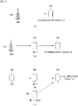
- Table 4 and FIGs. 3A to 3B illustrate a scenario that supports V2X operation based on both a Uu interface and a PC5 interface.
- FIG. 3A illustrates scenario 3A of Table 4
- FIG. 3B illustrates scenario 3B of Table 4.
- [Table 4] - This scenario supports V2V operation using both Uu and PC5.
- Scenario 3A In this scenario, a UE transmits a V2X message to other UEs in sidelink.
- One of the receiving UEs is a UE type RSU which receives the V2X message in sidelink and transmits it to E-UTRAN in uplink.
- E-UTRAN receives the V2X message from the UE type RSU and then transmits it to multiple UEs at a local area in downlink.
- E-UTRAN performs uplink reception and downlink transmission of V2X messages.
- E-UTRAN may use a broadcast mechanism.
- Scenario 3B In this scenario, a UE transmits a V2X message to E-UTRAN in uplink and E-UTRAN transmits it to one or more UE type RSUs. Then, the UE type RSU transmits the V2X message to other UEs in sidelink.
- E-UTRAN performs uplink reception and downlink transmission of V2X messages.
- E-UTRAN may use a broadcast mechanism.
- FIG. 4A through FIG. 4C are conceptual diagrams illustrating a synchronization method for PC5 link-based V2X communication that complies with D2D (ProSe) according to an embodiment of the present disclosure.
- a UE e.g., a V2X UE, that performs V2X communication may perform frequency synchronization and/or time synchronization for V2X communication based on a synchronization signal generated by a base station or by another UE.
- synchronization target UE is a term that indicates a UE that receives a synchronization signal for V2X communication. Also, a UE or an eNB that transmits a synchronization signal to a synchronization target UE is expressed using the term "synchronization source.”
- a synchronization source may be expressed using the term "original synchronization source” or "active synchronization source” if it is not synchronized by another synchronization source and if it transmits a synchronization signal generated based on its own reference synchronization to a synchronization target UE.
- a synchronization source excluding an active synchronization source from synchronization sources may be expressed using the term "passive synchronization source.” That is, at least one passive synchronization source may be synchronized by a single active synchronization source, and may transmit a synchronization signal to a synchronization target UE.
- an eNB is not synchronized by another UE or eNB and transmits a synchronization signal generated based on its own reference synchronization; thus, the eNB may be termed an active synchronization source.
- a UE that is not synchronized by another UE or eNB and operates as an active synchronization source may be expressed using the term "Independent Synchronization Source (ISS)."
- a synchronization method in V2X communication may roughly include three cases, that is, FIGS. 4A, 4B, and 4C , which are distinguished based on the following differences.
- FIG. 4A illustrates the case in which a synchronization target UE is synchronized by receiving a Primary Synchronization Signal (PSS) / Secondary Synchronization Signal (SSS) from an eNB.
- PSS Primary Synchronization Signal
- SSS Secondary Synchronization Signal
- FIGs. 4B and 4C illustrate the case in which a synchronization target UE is synchronized by receiving, from a UE, a Primary Sidelink Synchronization Signal (PSSS) / Secondary Sidelink Synchronization Signal (SSSS) which will be described below.
- FIGs. 4B and 4C are distinguished based on whether the active synchronization source is an eNB or an ISS.
- FIG. 4A discloses a method in which a synchronization target UE is synchronized based on a synchronization signal transmitted from an eNB in D2D communication.
- the synchronization source for D2D communication of a synchronization target UE 410 is an eNB 400, and the eNB 400 is an active synchronization source.
- the synchronization signal transmitted from the eNB 400 to the synchronization target UE 410 may be a Primary Synchronization Signal (PSS) / Secondary Synchronization Signal (SSS).
- PSS Primary Synchronization Signal
- SSS Secondary Synchronization Signal
- the synchronization target UE 410 may receive a PSS/SSS from the eNB, may execute frequency synchronization and/or time synchronization based on the received PSS/SSS, and may execute V2X communication with another UE.
- FIG. 4B illustrates the case in which a synchronization target UE 440 is synchronized by a UE 1 430.
- the UE 1 430 is a passive synchronization source synchronized by an eNB 420 which is an active synchronization source.
- a plurality of different passive synchronization sources may exist between the UE 1 430 and the eNB 420. For ease of description, it is assumed that the UE 1 430 is synchronized directly by the eNB 420.
- the UE 1 430 may be a passive synchronization source, which is synchronized based on a synchronization signal (PSS/SSS) transmitted from the eNB 420.
- the UE 1 430 synchronized by the eNB 420 may transmit a Sidelink Synchronization Signal (SLSS) to a synchronization target UE.
- the synchronization target UE may be synchronized with the UE 1 430 based on the SLSS received from the UE 1 430.
- An SLSS may include a Primary SLSS (PSSS) and a Secondary SLSS (SSSS).
- FIG. 4C illustrates the case in which a synchronization target UE 470 is synchronized by a UE 2 460.
- the UE 2 460 is a passive synchronization source that is synchronized by an ISS 450 which is an active synchronization source, or the UE 2 460 is an active synchronization source.
- the UE 2 460 is a passive synchronization source
- a plurality of different passive synchronization sources may exist between the UE 2 460 and the ISS 450.
- the synchronization target UE 470 may be synchronized based on an SLSS transmitted to the synchronization target UE 470.
- This SLSS may be transmitted from the UE 2 460 that operates as an active synchronization source or from the UE 2 460 that is synchronized based on the ISS 450 and operates as a passive synchronization source.
- the synchronization target UE 410 may obtain information associated with a Physical Cell Identity (PCID) of an eNB, based on a PSS/SSS, as in the LTE system.
- PCID Physical Cell Identity
- the synchronization target UE 440 and 470 may obtain identity information of an active synchronization source based on the SLSS.
- the identity information of a synchronization source may be expressed using the term "Physical-layer Sidelink Synchronization Identity (PSSID)."
- PSSID Physical-layer Sidelink Synchronization Identity
- the identity information of the passive synchronization source uses the identity information of the active synchronization source, and thus, the identity information of the synchronization source (PSSID) may actually be the identity information of the active synchronization source.
- a sidelink is used to express a communication link between UEs, instead of using an uplink or a downlink.
- the synchronization target UE 440 and 470 may obtain the identity information of the active synchronization source based on an SLSS.
- the identity information of an active synchronization source corresponding to the eNB 420 may be obtained by the synchronization target UE 440 based on an SLSS.
- the identification information of an active synchronization source corresponding to the ISS 450 may be obtained based on an SLSS.
- the synchronization target UE 440 and 470 may obtain identity information of an eNB or identity information of an ISS that operates as an active synchronization source, based on the identity information (PSSID) of the active synchronization source.
- PSSID identity information
- an SLSS may be generated based on one of the sequences included in a D2DSSue_net set.
- the active synchronization source is the ISS 450, as illustrated in FIG. 4C
- an SLSS may be generated based on one of the sequences included in a D2DSSue_oon set.
- the synchronization target UE 440 and 470 may receive a synchronization signal generated based on a different sequence set according to whether the active synchronization source is the eNB 420 or the ISS 450.
- D2DSSue_net may be expressed using the term "eNB source sequence set”
- D2DSSue_oon may be expressed using the term "UE source sequence set”.
- the synchronization target UE 440 and 470 may determine whether the active synchronization source is the eNB 420 or the ISS 450, based on information associated with a sequence that generates a received SLSS.
- V2X may perform synchronization according to a Global Navigation Satellite System (GNSs) or a GNSS-equivalent device. That is, a GNSS or a GNSS-equivalent device needs to be considered a synchronization source, in addition to an eNB or a UE. In this instance, in FIGs.
- GSSs Global Navigation Satellite System
- a GNSS or a GNSS-equivalent device may be used as an original synchronization source (or an active synchronization source), instead of an eNB or a UE.
- a synchronization process from the GNSS (or the GNSS-equivalent device corresponding to the original synchronization source, i.e. the active synchronization source) to a UE corresponding to a passive synchronization source may be equivalently applied as described above.
- the number of physical-layer cell identities is 504.
- the physical layer cell identities are grouped into 168 physical-layer cell-identity groups. In this instance, each group includes three unique identities.
- a physical layer cell identity N cell ID is defined as 3N (1) ID +N (2) ID .
- the physical layer cell identity N cell ID may be determined by N (1) ID and N (2) ID .
- N (1) ID indicates a physical-layer cell-identity group and has a value in the range of 0 to 167.
- N (2) ID indicates a physical layer identity in a physical-layer cell-identity group and has a value in the range of 0 to 2.
- a PSS may be generated based on the Zadoff-Chu sequence provided below.
- Equation 1 u is a root index value, and may be determined as one of the values listed in Table 5. [Table 5] N (2) ID Root Index u 0 25 1 29 2 34
- a PSS may be generated based on a root index that is selected from among 25, 29, and 34.
- N (2) ID that determines a root index may be selected based on a PCID of an eNB that transmits a PSS.
- Mapping a sequence to a resource element may be determined based on a frame structure.
- a UE may determine that a PSS is not transmitted together with a downlink reference signal through the same antenna port. Also, the UE estimates that a transmission instance of a PSS and a transmission instance of another PSS are not transmitted through the same antenna port.
- a sequence d(n) used for the PSS may be mapped to a resource element based on Equation 2.
- N DL RB denotes the number of downlink resource blocks (RBs).
- RB SC denotes the number of subcarriers in a single resource block.
- a PSS is mapped to the last OFDM symbols of slots 1 and 10.
- a PSS is mapped to the last OFDM symbols of slots 1 and 6.
- a resource element corresponding to Equation 3 from among resource elements (k, 1) of OFDM symbols used for transmitting a PSS may not be used, but may be reserved for transmission of the PSS.
- a sequence d(0),...,d(61) used for an SSS may be generated based on an interleaved combination of two m-sequences having a length of 31, as defined in Equation 4 below.
- the sequence combination may be scrambled based on a scrambling sequence given by a PSS.
- the combination of two m-sequences having a length of 31, which defines the SSS, may have different values between a subframe 0 and a subframe 5, based on Equation 4.
- n 0 ⁇ n ⁇ 30, and an index m0 and an index m1 are values derived from a Physical Cell Identity Group (PCID group) N (1) ID according to Equation 5 provided below.
- PCID group Physical Cell Identity Group
- m 0 m ′ mod31
- m 1 m 0 + ⁇ m ′ / 31 ⁇ + 1 mod31
- m ′ N ID 1 + q q + 1 / 2
- q ⁇ N ID 1 + q ′ q ′ + 1 / 2 30 ⁇
- q ′ ⁇ N ID 1 / 30 ⁇
- N (1) ID may be determined based on a PCID of an eNB that transmits the SSS. That is, the SSS may be determined based on the value of PCID group N (1) ID .
- Equation 5 A result value of Equation 5 may be expressed as shown in Table 6.
- N (1) ID 0 m 0 0 m 1 1 N (1) ID 34 m 0 4 m 1 6 N (1) ID 68 m 0 9 m 1 12 N (1) ID 102 m 0 15 m 1 19 N (1) ID 136 m 0 22 m 1 27 1 1 2 35 5 7 69 10 13 103 16 20 137 23 28 2 2 3 36 6 8 70 11 14 104 17 21 138 24 29 3 3 4 37 7 9 71 12 15 105 18 22 139 25 30 4 4 5 38 8 10 72 13 16 106 19 23 140 0 6 5 5 6 39 9 11 73 14 17 107 20 24 141 1 7 6 6 7 40 10 12 74 15 18 108 21 25 142 2 8 7 7 8 41 11 13 75 16 19 109 22 26 143 3 9 8 8 9 42 12 14 76 17 20 110 23 27 144 4 10 9 9 10 43 13 15 77 18 21 111 24 28 145 5 11 10 10 11 44 14 16
- Two sequences s0 (m0) (n) and s1 (m1) (n) may be defined as two different cyclic shifts of an m-sequence s ⁇ ( n ), based on Equation 6.
- s 0 m 0 n s ⁇ n + m 0 mod31
- s 1 m 1 n s ⁇ n + m 1 mod31
- x i ⁇ + 5 x i ⁇ + 2 + x i ⁇ mod2 , 0 ⁇ i ⁇ ⁇ 25
- c 0 (n) and c 1 (n) which are two scrambling sequences may be determined based on a PSS, and may be defined by two different cyclic shifts of an m-sequence c ⁇ ( n ) based on Equation 8.
- c 0 n c ⁇ n + N ID 2 mod31
- c 1 n c ⁇ n + N ID 2 + 3 mod31
- Scrambling sequences z 1 (m0) (n) and z 1 (m1) (n) are defined by a cyclic shift of an m-sequence z ⁇ ( n ) based on Equation 10.
- z 1 m 0 n z ⁇ n + m 0 mod8 mod31
- z 1 m 1 n z ⁇ n + m 1 mod8 mod31
- x(i) may be defined by Equation 11.
- x i ⁇ + 5 x i ⁇ + 4 + x i ⁇ + 2 + x i ⁇ + 1 + x i ⁇ mod2 , 0 ⁇ i ⁇ ⁇ 25
- a sequence d(n) used for the SSS may be mapped to a resource element based on Equation 12.
- N DL RB denotes the number of downlink resource blocks (RBs).
- RB SC denotes the number of subcarriers in a single resource block.
- a resource element corresponding to Equation 13 from among resource elements (k, 1) in symbols may not be used but for transmission of an SSS.
- s 0 (m0) (n) and s 1 (m1) (n) , c 0 (n) and c 1 (n), and z 1 (m0) (n) and z 1 (m1) (n) are m-sequences each having a length of 31.
- N (1) ID is an integer in the range from 0 to 167, and each integer may correspond to one of the 168 sequences.
- An eNB may generate a PSS/SSS based on N (2) ID and N (1) ID corresponding to an allocated PCID.
- a UE may obtain N (2) ID based on a PSS received from an eNB, and also may obtain N (1) ID based on an SSS received from the eNB.
- N ID SL indicates a physical-layer sidelink synchronization identity, and has a relationship of N ID SL ⁇ 0 , 1 ,... 335 .
- N ID SL may be divided into id_net and id_oon, which are two sets that include identities ⁇ 0,1,...,167 ⁇ and ⁇ 168,169,...,335 ⁇ , respectively.
- the PSSS is transmitted through two adjacent SC_FDMA symbols in the same subframe.
- a root index u is 26 when N ID SL ⁇ 167 is satisfied. Otherwise, the root index u is 37.
- a sequence d i ( n ) may be multiplied by an amplitude scaling factor 72 / 62 ⁇ ⁇ PSBCH , and may be mapped to a resource element on an antenna port 1020 according to Equation 14.
- the SSSS is transmitted through two adjacent SC_FDMAs in the same subframe.
- a sequence d i ( n ) may be multiplied by an amplitude scaling factor ⁇ SSSS , and may be mapped to a resource element on the antenna port 1020 in the second slot of a subframe according to Equation 15.
- a PSS/SSS is a synchronization signal transmitted from an eNB.
- m o and m 1 values as shown in Table 6 may be determined from one of the 168 integer values in the range of 0 to 167 (a parameter for 168 values is N (1) ID ), and the SSS is configured from the m o and m 1 values.
- a PSS is transmitted in two predetermined subframes with a period of 10ms, and a single symbol is used in each subframe.
- An SSS is also transmitted in two predetermined subframes with a period of 10ms, and a single symbol is used in each subframe.
- An SLSS is a synchronization signal transmitted from a UE.
- PSSS PSSS
- a sequence is configured based on the Zadoff-Chu sequence, in the same manner of a PSS configuration.
- the basic sequence configuration method of the SLSS complies with the above described PSS/SSS sequence generating method, i.e., a method for configuring a sequence based on an interleaved combination of two m-sequences having a length of 31, in the same manner as an SSS, except for some points described below.
- m o and m 1 values as shown in Table 6 may be determined from a value out of 168 integer values in the range of 0 to 167 (a parameter associated with 168 values corresponds to N (1) ID ) in the same manner as an SSS, and the SSSS is configured from the m o and m 1 values.
- the PSSS/SSSS of the SLSS is mapped to two symbols in a single subframe based on a period of 40ms, as illustrated in FIGs. 5 and 6 .
- the same sequences may be used for two symbols (1, 2 for Normal CP and Extended CP) for the PSSS and two symbols (11, 12 for Normal CP and 9, 10 for Extended CP) for the SSSS.
- a UE in the PC5 link-based D2D receives synchronization signals from a plurality of synchronization sources, selects one of the received synchronization signals as its own synchronization (that is, its own time reference), and transmits a synchronization corresponding to the time reference as an SLSS (PSSS and SSSS) which is a synchronization signal.
- the UE selects its own synchronization (that is, its own time reference) out of the synchronization signals received from the plurality of synchronization sources, based on priority provided below.
- a synchronization signal having a high transmission power that is, a synchronization signal having the highest S-RSRP result, may be selected when synchronization signals have the same priority.
- V2X may perform synchronization according to a Global Navigation Satellite System (GNSS) or a GNSS-equivalent device, as illustrated in FIG. 7 . That is, according to an embodiment of the present disclosure, a synchronization source may consider a GNSS or a GNSS-equivalent device, in addition to an eNB or a UE.
- GNSS Global Navigation Satellite System
- FIG. 7 a synchronization source may consider a GNSS or a GNSS-equivalent device, in addition to an eNB or a UE.
- the UE may be classified in two levels.
- a UE in the PC5-based D2D considers the priority corresponding to 1 through 5 when selecting a time reference from among synchronization signals received from a plurality of synchronization sources, and when transmitting a synchronization signal.
- V2X considers the priority corresponding to 1 through 5, and considers the priority corresponding to a and b(or b-1 and b-2) by additionally taking the GNSS or the GNSS-equivalent device into account.
- V2X may consider the priority shown in Table 7, as provided below. Although Table 7 lists five cases, the priority of V2X synchronization sources may not be limited thereto.
- an SLSS transmitted from an out-of-coverage UE that is directly synchronized by a GNSS is distinguished from an SLSS transmitted from a UE that has a coverage indicator with a field value of 1, and has a PSSID belonging to SLSS_net.
- This case may be included in the example 'b-1 >2'.
- an SLSS may be transmitted from an in-coverage UE that is directly synchronized by a GNSS (or a GNSS-equivalent device having sufficient reliability), has the same priority as an SLSS transmitted from a UE that has a coverage indicator with a field value of 1, and has a PSSID belonging to SLSS_net.
- a GNSS (or a GNSS-equivalent device: GNSS indicates a GNSS or a GNSS-equivalent device) always has a higher priority than an eNB.
- the priority must belong to a GNSS in an area where an eNB does not exist, and in an area where an eNB exists and sets a synchronization signal based on a GNSS, the GNSS has more accurate synchronization information when a predetermined error is considered.
- the present disclosure also considers that a smaller number of hops are used when a synchronization signal is transmitted from an initial synchronization source (eNB, GLSS, or UE).
- the present disclosure proposes a method of generating a synchronization signal based on a GNSS timing to be distinguished according to the priority. That is, the UE needs to distinguish synchronization signals generated in case b (or b-1 and b-2), which directly selects a synchronization signal from a GNSS and transmits a synchronization signal based on GNSS timing, from synchronization signals generated in cases 1through 5.
- the present disclosure proposes a method of generating a synchronization signal in consideration of the above. Also, when two cases b-1 and b-2 are taken into consideration, the present disclosure provides a method of distinguishing synchronization signals generated from the two cases.
- the case of synchronization by 2 and 3 is referred to as an 'eNB timing-based synchronization' case
- the case of synchronization by 4 and 5 is referred to as a 'UE timing-based synchronization' case
- the case of synchronization by b(or b-1 and b-2) is referred to as a 'GNSS timing-based synchronization' case.
- Embodiment 1 the case of taking into consideration a GNSS timing-based synchronization signal transmission b.
- a root index of 26 is used for a PSSS.
- a root index of 37 is used for a PSSS.
- Case b (i.e., the GNSS timing-based synchronization case): For the synchronization based on an eNB timing or a UE timing, a root index of 26 or 37 may be used for a PSSS. In case 3, 4, and 5 of Table 7, b may always have a higher priority than the UE timing-based synchronization case (i.e., 4 or 5), and also, the eNB timing-based synchronization case (i.e., 2 or 3) always has a higher priority than the UE timing-based synchronization case (i.e., 4 or 5).
- the GNSS timing-based synchronization case (i.e., b) may also consider using the same index as the eNB timing-based synchronization case (i.e., 2 or 3). That is, in case b, a root index of 26 may be used for a PSSS, in the same manner as 2 or b.
- a root index value applied to the GNSS timing-based synchronization case may have a value different from the root index value that the eNB applied to the synchronization case (i.e., 1) and different from the UE timing-based synchronization case, and thus, their primary synchronization signals (i.e., a PSS or PSSS) may be distinguished from one another.
- the root index value applied to the GNSS timing-based synchronization case is the same as the root index value applied to the eNB timing-based synchronization case, and thus, their primary synchronization signals (i.e., PSSS) may not be distinguishable from each other. Accordingly, the GNSS timing-based synchronization case and the eNB timing-based synchronization case may need to be distinguished by additionally using a secondary synchronization signal (SSSS).
- SSSS secondary synchronization signal
- a secondary synchronization signal (i.e., SSS or SSSS) generated in each case may be distinguished as follows.
- An SSSS may be mapped to two symbols in an SLSS transmission subframe.
- a mapping scheme of the SSSS with respect to each symbol may comply with a mapping scheme on subframe 0 from among two mapping schemes that have been described with reference to Equation 4.
- the mapping scheme on subframe 0 may be defined by Equation 16.
- indices m 0 and m 1 may be interleaved and mapped to each subcarrier in order from m 0 to m 1 .
- An SSSS may be mapped to two symbols in an SLSS transmission subframe.
- a mapping scheme of the SSSS with respect to each symbol may comply with a mapping scheme on subframe 0 from among two mapping schemes that have been described with reference to Equation 4.
- indices m 0 and m 1 may be interleaved and mapped to each subcarrier in order from m 0 to m 1 .
- An SSSS may be mapped to two symbols in an SLSS transmission subframe.
- a mapping scheme of the SSSS with respect to each symbol may comply with a mapping scheme on subframe 5 from among two mapping schemes that have been described with reference to Equation 4.
- the mapping scheme on subframe 5 may be defined by Equation 17 as provided below.
- m 0 ⁇ m 1 Accordingly, in association with a binary sequence having a length of 31 (length-31 binary sequence), which is mapped to even-numbered subcarriers and is transmitted, and a binary sequence having a length of 31, which is mapped to odd-numbered subcarriers and is transmitted, whether the binary sequences respectively comply with indices m 0 and m 1 (i.e., the mapping scheme on subframe 0 from among two SSS mapping schemes) and whether the binary sequences respectively comply with indices m 1 and m 0 (i.e., the mapping scheme on subframe 5 from among the two SSS mapping schemes) may be distinguished.
- indices m 0 and m 1 i.e., the mapping scheme on subframe 0 from among two SSS mapping schemes
- indices m 1 and m 0 i.e., the mapping scheme on subframe 5 from among the two SSS mapping schemes
- an SSSS for each case may be distinguished by setting different mapping schemes for the GNSS timing-based synchronization case (i.e., b) and the eNB timing-based synchronization case (i.e., 2 and 3).
- Embodiment 2 the case of taking into consideration a GNSS timing-based synchronization signal transmission b-1 and b-2
- a root index of 26 is used for a PSSS.
- a root index of 37 is used for a PSSS.
- case b i.e., the GNSS timing-based synchronization case
- a root index of 26 or 37 may be used for a PSSS.
- cases 1 and 2 of Table 7 it is recognized that b-1 and b-2 always have a higher priority than the UE timing-based synchronization case (i.e., 4 or 5), and also, the eNB timing-based synchronization case (i.e., 2 or 3) always has a higher priority than the UE timing-based synchronization case (i.e., 4 or 5).
- the GNSS timing-based synchronization case (i.e., b-1 or b-2) may also consider using the same index as the eNB timing-based synchronization case (i.e., 2 or 3). That is, in case b-1 or b-2, a root index of 26 may be used for a PSSS, in the same manner as 2 or 3.
- a root index value applied to the GNSS timing-based synchronization case may have a value different from the root index value applied to a synchronization case by an eNB (i.e., 1) or from the UE timing-based synchronization case (4 or 5), and thus, their primary synchronization signals (i.e., a PSS or PSSS) may be distinguished from one another.
- a root index value applied to the GNSS timing-based synchronization case is the same as the root index value applied to the eNB timing-based synchronization case, and thus, their synchronization signals (i.e., a PSSS) may not be distinguished from one another. Accordingly, the GNSS timing-based synchronization case and the eNB timing-based synchronization case may need to be distinguished by additionally using a secondary synchronization signal (SSSS).
- SSSS secondary synchronization signal
- a secondary synchronization signal (i.e., SSS or SSSS) generated in each case may be distinguished as follows.
- An SSSS may be mapped to two symbols in an SLSS transmission subframe.
- a mapping scheme of the SSSS with respect to each symbol may comply with a mapping scheme on subframe 0 from among two mapping schemes that have been described with reference to Equation 4.
- indices m 0 and m 1 may be interleaved and mapped to each subcarrier in order from m 0 to m 1 .
- An SSSS may be mapped to two symbols in an SLSS transmission subframe.
- a mapping scheme of the SSSS with respect to each symbol may comply with a mapping scheme on subframe 5 from among two mapping schemes that have been described with reference to Equation 4.
- indices m 0 and m 1 may be interleaved and mapped to each subcarrier in order from m 1 to m 0 .
- the binary sequences may be distinguished based on whether they respectively comply with indices m 0 and m 1 (i.e., the mapping scheme on subframe 0 from among two SSS mapping schemes) or whether they respectively comply with indices m 1 and m 0 (i.e., the mapping scheme on subframe 5 from among the two SSS mapping schemes).
- an SSSS for each case may be distinguished by setting different mapping schemes for the GNSS timing-based synchronization case (i.e., b-1 and b-2) and the eNB timing-based synchronization case (i.e., 2 and 3).
- the field value of a coverage indicator transmitted through a PSBCH may have a value of 1.
- the field value of a coverage indicator transmitted through a PSBCH may have a value of 0.
- FIG. 8 is a diagram illustrating one method of selecting a synchronization signal according to the present disclosure.
- FIG. 8 may be applied to synchronization between a passive synchronization source and a synchronization target UE.
- a first UE is a passive synchronization source
- a second UE is a synchronization target UE.
- the first UE receives at least one synchronization signal from an external source.
- the first UE may receive a synchronization signal from an active synchronization source (such as an eNB, a GNSS, another UE, or the like) or from another passive synchronization source (which is synchronized by an active synchronization source).
- an active synchronization source such as an eNB, a GNSS, another UE, or the like
- another passive synchronization source which is synchronized by an active synchronization source.
- the synchronization signal received by the first UE may include a primary synchronization signal (i.e., a PSS or PSSS) and a secondary synchronization signal (i.e., a SSS or SSSS), and they may be generated according to the methods which have been described in the embodiment 1 and the embodiment 2.
- a primary synchronization signal i.e., a PSS or PSSS
- a secondary synchronization signal i.e., a SSS or SSSS
- the first UE determines the priority of the plurality of signals based on a root index of the received synchronization signal in operation S820. For example, the first UE may determine the priority of synchronization signals according to one of the cases 1 through 5, which have been described in Table 6.
- the priority may be determined based on an index sequence associated with a binary sequence of an SSSS.
- a field value of a coverage indicator of a PSBCH may be used for determining the priority.
- the first UE performs synchronization based on the synchronization signal with the highest priority.
- the first UE transmits the synchronization signal selected in operation S830 to a second UE.
- FIG. 9 is a block diagram schematically illustrating an apparatus according to an embodiment of the present disclosure.
- a first communication device 900 and a second communication device 950 execute V2X communication.
- the communication device may be a V2X UE that performs V2X communication.
- the first communication device 900 includes a processor 910, an RF unit 920, and a memory 925.
- the processor 910 may include a sequence generating unit and a sequence mapping unit.
- the sequence generating unit generates a sequence and determines the generated sequence.
- the sequence mapping unit maps a sequence generated from the sequence generating unit, and determines mapping.
- the processor 910 may implement the functions, processes, and/or methods proposed in the present specifications. Particularly, the processor 910 may perform all operations of a V2X UE of FIG. 3 through FIG. 7 disclosed in the present specification, and may perform the operation of generating a sequence corresponding to a PSSS and an SSSS and mapping the sequence according to an embodiment.
- the processor 910 determines the priority of the plurality of synchronization signals, performs synchronization based on a synchronization signal taking precedence, and transmits the synchronization signal based on the same.
- the processor 910 determines at least one synchronization signal received through the RF module 920. In this instance, in association with the synchronization signal, the processor determines whether an original synchronization source (or active synchronization source) is an eNB, a UE, or a GNSS/GNSS-equivalent.
- the processor determines whether the synchronization signal corresponds to 1 a synchronization signal transmitted from an eNB; 2 a synchronization signal transmitted from an in-coverage UE 3 a synchronization signal transmitted from an out-of-coverage UE where a PSSID is an ID belonging to id_net; 4 a synchronization signal transmitted from an out-of-coverage UE where a PSSID is an ID belonging to id_oon; or a case in which a synchronization signal corresponding to 1 through 4, or a or b (or b-1 and/or b-2) is not selected (i.e., a case in which a UE itself acts as a synchronization source and transmits a synchronization signal).
- the synchronization signal corresponds to a a synchronization signal transmitted from a GNSS or a GNSS-equivalent device; or b (or b-1 and/or b-2) a signal transmitted from a UE that transmits an SLSS, which is based on a GNSS/GNSS-equivalent device timing.
- the processor 910 may determine a root index through a PSS or PSSS sequence of at least one received synchronization signal. For example, in case 1, it may be determined whether a root index is one of 25, 29, and 34 used for a PSS. For case 4 and a case that does not correspond to 1 to 4, and a or b (or b-1, b-2), it may be determined that a root index is 37. For case 2, 3 or b (or b-1 and/or b-2), it may be determined that a root index for a PSSS is 26.
- the processor 910 may determine at least one SSSS sequence to distinguish 2, 3 and b (or b-1 and/or b-2).
- N (1) ID may be determined.
- a PSSID may be determined.
- a subframe 0 scheme may be used for mapping an SSSS to an SLSS subframe.
- a subframe 5 scheme may be used for mapping an SSSS to an SLSS subframe.
- Case b may be classified in detail.
- the processor 910 may determine a field value of a coverage indicator transmitted through a PSBCH, in order to distinguish b-1 a synchronization signal transmitted from a UE that is directly synchronized by a GNSS or a GNSS-equivalent device and a synchronization signal transmitted from a UE synchronized by the UE corresponding to b-1.
- the field value of the coverage indicator is 1, it corresponds to b-1.
- the field value of the coverage indicator is 0, it corresponds to b-2.
- the processor 910 may further determine whether the synchronization signal is a signal transmitted from a UE that transmits an SLSS, which is based on a GNSS or GNSS-equivalent device timing, through a root index determined through the PSSS sequence or a PSSID determined through the PSSS/SSSS sequence.
- the processor 910 may determine and compare at least one determined synchronization signal, and may select a synchronization signal by taking into consideration priorities that may be obtained through the combinations of cases 1, 5, 3, and 4, and cases a and b (or b-1 and/or b-2).
- selecting a synchronization signal may include the case in which a UE itself acts as a synchronization source and transmits a synchronization signal.
- case a takes precedence over cases 1, 2, 3, and 4 and selects a synchronization signal.
- Case b (or b-1 and/or b-2) takes precedence over one or more of cases 1, 2, 3, and 4 and selects a synchronization signal.
- the present disclosure may include selecting a final synchronization signal by taking into consideration how a smaller number of hops is used when a synchronization signal is transmitted from the original synchronization source (eNB, GNSS, or UE).
- the processor may control selecting a synchronization signal based on whether the number of used hops is greater/less than or equal to a predetermined number.
- the processor 910 may determine whether to transmit a synchronization signal selected through the RF module 920 to the second communication device.
- the memory 925 is connected to the processor 910, and stores various pieces of information for driving the processor 910. According to the present disclosure, the memory 925 may store root index information and PSSID information in association with a synchronization signal.
- the RF unit 920 is connected to the processor 910, and transmits and/or receives a wireless signal.
- the RF module 920 may receive at least one synchronization signal according to the present disclosure, and may transmit a selected synchronization signal, which is controlled by the processor 910, to the second communication device 950.
- the RF module 920 may transmit a PSSS and/or SSSS under the control of the processor 910, or may transmit a PSSS and/or SSSS.
- the second communication device 950 may have a structure identical to the first communication device 900, and may transmit or receive a PSSS and/or an SSSS to/ from the first communication device 900.
- the second communication device 950 may include a processor 960, a memory 975, and an RF module 970.
- the RF module 970 may receive one or more synchronization signals and the processor 970 may prioritize the received one or more synchronization signals.
- the RF module 970 may receive a synchronization signal including a primary synchronization signal (PSS) and a secondary synchronization signal (SSS) from an evolved NodeB.
- PSS primary synchronization signal
- SSS secondary synchronization signal
- the processor 960 may determine a root index from the PSS and determine, based on determining that the root index is 25, 29, or 34, that the synchronization signal was transmitted from an evolved NodeB.
- the RF module 970 may receive a sidelink synchronization signal from another device, e.g., a UE or V2X device.
- the sidelink synchronization signal may include a primary sidelink synchronization signal (PSSS) and a secondary sidelink synchronization signal (SSSS).
- PSSS primary sidelink synchronization signal
- SSSS secondary sidelink synchronization signal
- the PSSS is mapped in two SC-FDMA symbols in one subframe.
- the SSSS is mapped in different two SC-FDMA symbols in the same subframe.
- the processor 960 may determine whether the transmitter of the SSSS is operating in a mode that supports synchronization with a GNSS (including GNSS-equivalent).
- the processor 960 may determine that the transmitter of the SSSS is operating in a mode in which the active synchronization source cannot be a GNSS or GNSS-equivalent.
- the processor 960 may determine one synchronization timing from amongst a plurality of synchronization signals received by the RF module 970. Based on values derived from the synchronization signal selected for the determined synchronization timing, the processor 960 determine PSSID value to generate its own synchronization signal to be transmitted to another device. For example, a root index may be determined from the determined PSSID. A PSSS may be generated based on the determined root index. Further, based on the determined PSSID, m0 and m1 indices are determined (e.g., see Table 6), where m0 ⁇ m1.
- the processor When the selected synchronization source is a GNSS (or GNSS-equivalent) or the selected synchronization source is synchronized to the timing of a GNSS (or GNSS-equivalent), the processor generates an SSSS by generating the first length-31 sequence d(2n) based on s 1 (m1) (n) and generating the second length-31 sequence d(2n+1) based on s 0 (m0) (n) .
- the generated PSSS may be mapped to two consecutive SC-FDMA symbols in one subframe and the generated SSSS may be mapped to other two consecutive SC-FDMA symbols in the same subfame as shown in FIG. 6 .
- the SSSS mapped to the other two consecutive SC-FDMA symbols may be mapped to subcarriers as described above in Equations 15 and 17.
- the first length-31 sequence d(2n) based on s 1 (m1) (n) and the second length-31 sequence d(2n+1) based on s 0 (m0) (n) are alternately mapped to 62 consecutive subcarriers as described in Equation 15.
- d(0) based on s 1 (m1) (n) is mapped to the lowest index of the 62 consecutive subcarriers and d(61) based on s 0 (m0) (n) is mapped to the highest index of the 62 consecutive subcarriers.
Landscapes
- Engineering & Computer Science (AREA)
- Signal Processing (AREA)
- Computer Networks & Wireless Communication (AREA)
- Remote Sensing (AREA)
- Radar, Positioning & Navigation (AREA)
- Physics & Mathematics (AREA)
- General Physics & Mathematics (AREA)
- Health & Medical Sciences (AREA)
- Medical Informatics (AREA)
- General Health & Medical Sciences (AREA)
- Computing Systems (AREA)
- Discrete Mathematics (AREA)
- Mathematical Physics (AREA)
- Mobile Radio Communication Systems (AREA)
- Synchronisation In Digital Transmission Systems (AREA)
Claims (14)
- Verfahren zur Auswahl eines Synchronisationssignals, wobei das Verfahren aufweist:Bestimmen mehrerer Synchronisationssignale, die von mehreren Synchronisationsquellen übertragen werden, durch ein erstes drahtloses Benutzergerät (410, 430, 440, 450, 460, 470, 900, 950), wobei die mehreren Synchronisationsquellen aufweisen: einen evolved NodeB, eNB (400, 420), ein globales Navigationssatellitensystem, GNSS, ein zum Synchronisieren mit einem eNB ausgebildetes Gerät, und ein zum Synchronisieren mit einem GNSS ausgebildetes Gerät;gekennzeichnet durchSynchronisieren, eines Timings eines ersten Sidelink-Synchronisationssignals, das aus den bestimmten Synchronisationssignalen ausgewählt ist, durch das erste drahtlose Benutzergerät (410, 430, 440, 450, 460, 470, 900, 950), wobei das Timing des ersten Sidelink-Synchronisationssignals mit einem Synchronisations-Timing des GNSS assoziiert ist, und wobei das erste Sidelink-Synchronisationssignal von einem zweiten drahtlosen Benutzergerät übertragen wird,wobei das Synchronisieren des Timings des ersten Sidelink-Synchronisationssignals aufweist:Bestimmen eines Subframes, auf den ein primäres Sidelink-Synchronisationssignal, PSSS, des ersten Sidelink-Synchronisationssignals abgebildet wird; undBestimmen eines sekundären Sidelink-Synchronisationssignals, SSSS, des ersten Sidelink-Synchronisationssignals aus 62 aufeinanderfolgenden Subcarrier von zwei aufeinanderfolgenden Monofrequenz-Frequenzmultiplex-Vielfachzugriff-, SC-FDMA,-Symbolen in dem bestimmten Subframe,wobei das SSSS eine erste Länge-31-Sequenz aufweist, die auf der Grundlage von m1 erzeugt ist, und eine zweite Länge-31-Sequenz aufweist, die auf der Grundlage von m0 erzeugt ist, wobei m1 größer als m0 ist,wobei ein Teil der ersten Länge-31-Sequenz basierend auf einem ersten Abbildungsschema von zwei Abbildungsschemata auf einen Subcarrier mit einem niedrigsten Index unter den 62 aufeinanderfolgenden Subcarriern abgebildet wird, und ein Teil der zweiten Länge-31-Sequenz auf einen Subcarrier mit einem höchsten Index unter den 62 aufeinanderfolgenden Subcarriern abgebildet wird, undwobei das erste Abbildungsschema das erste Sidelink-Synchronisationssignal von Sidelink-Synchronisationssignalen unterscheidet, die ein zweites Abbildungsschema der beiden Abbildungsschemata verwenden.
- Verfahren nach Anspruch 1, wobei die abgebildeten erste Länge-31-Sequenz und zweite Länge-31-Sequenz miteinander verschachtelt sind.
- Verfahren nach Anspruch 1 oder 2, ferner aufweisend:Priorisieren der mehreren Synchronisationssignale, wobei ein Synchronisationssignal eines Gerätes, das direkt mit einem GNSS synchronisiert ist, und ein Synchronisationssignal eines Benutzergerätes, das direkt mit einem eNB synchronisiert ist, gegenüber einem Synchronisationssignal eines Benutzergerätes, das indirekt mit einem GNSS synchronisiert ist, undgegenüber einem Synchronisationssignal eines Benutzergerätes, das indirekt mit einem eNB synchronisiert ist, priorisiert werden.
- Verfahren nach einem der Ansprüche 1 bis 3, wobei das erste Abbildungsschema einem Abbildungsschema eines sekundären Synchronisationssignals, SSS, in Subframe 5 entspricht.
- Verfahren nach einem der Ansprüche 1 bis 4, wobei das zweite Abbildungsschema einem Abbildungsschema eines sekundären Synchronisationssignals, SSS, im Subframe 0 entspricht.
- Verfahren nach einem der Ansprüche 1 bis 5, ferner aufweisend:Bestimmen eines von einem mit einem eNB synchronisierten Benutzergerät übertragenen anderen Synchronisationssignals,wobei das andere Synchronisationssignal ein anderes SSSS aufweist, das auf andere 62 aufeinanderfolgende Subcarrier in einem anderen Subframe abgebildet ist, undwobei das andere SSSS eine andere erste Länge-31-Sequenz, die auf der Grundlage von m0 erzeugt wurde, und eine andere zweite Länge-31-Sequenz, die auf der Grundlage von m1 erzeugt wurde, aufweist, undwobei basierend auf dem zweiten Abbildungsschema der beiden Abbildungsschemata ein Teil der anderen ersten Länge-31-Sequenz auf einen Subcarrier mit einem niedrigsten Index unter den anderen 62 aufeinanderfolgenden Subcarriern abgebildet wird, und ein Teil der anderen zweiten Länge-31-Sequenz auf einen Subcarrier mit einem höchsten Index unter den anderen 62 aufeinanderfolgenden Subcarriern abgebildet wird.
- Verfahren nach Anspruch 1, ferner aufweisend:Auswählen des Synchronisationssignals unter anderen Synchronisationssignalen auf der Grundlage einer Priorität,wobei ein Synchronisationssignal eines Geräts, das direkt mit einem GNSS synchronisiert ist, gegenüber einem Synchronisationssignal eines Geräts, das indirekt mit einem GNSS synchronisiert ist, oder gegenüber einem Synchronisationssignal eines Geräts, das indirekt mit einem eNB (400, 420) synchronisiert ist, priorisiert ist, undwobei ein Synchronisationssignal eines Gerätes, das indirekt mit einem GNSS synchronisiert ist, und ein Synchronisationssignal eines Gerätes, das indirekt mit einem eNB synchronisiert ist, gegenüber einem Benutzergerät, das nicht mit einem GNSS oder mit einem eNB synchronisiert ist, priorisiert sind.
- Verfahren nach Anspruch 7, wobei ein Synchronisationssignal eines Geräts, das direkt mit einem eNB (400, 420) synchronisiert ist, gegenüber einem Synchronisationssignal eines Geräts, das indirekt mit einem GNSS synchronisiert ist, priorisiert ist.
- Verfahren nach einem der Ansprüche 1 bis 8, ferner aufweisend:
Bestimmen des Root-Index 26 oder des Root-Index 37 auf der Grundlage des PSSS. - Verfahren nach einem der Ansprüche 1 bis 9, wobei Gerät-zu-Gerät-, D2D, -Sidelink-Synchronisationsquellen einen eNB und ein Benutzergerät aufweisen.
- Verfahren nach einem der Ansprüche 1 bis 10, wobei Fahrzeug-zu-Alles-, V2X, -Sidelink-Synchronisationsquellen ein GNSS, ein GNSS-äquivalentes Gerät, einen eNB und ein Benutzergerät aufweisen.
- Drahtloses Benutzergerät, aufweisend:einen oder mehrere Prozessoren;ein Hochfrequenzmodul; undeinen Speicher, der Anweisungen speichert, die, wenn sie von dem einen oder den mehreren Prozessoren ausgeführt werden, das drahtlose Benutzergerät dazu veranlassen, das Verfahren nach einem der Ansprüche 1 bis 11 auszuführen.
- System, aufweisend:ein drahtloses Benutzergerät zur Ausführung des Verfahrens nach einem der Ansprüche 1 bis 11; undeinen evolved NodeB, um an das drahtlose Benutzergerät ein primäres Synchronisationssignal, PSS, und ein sekundäres Synchronisationssignal, SSS, zu übertragen.
- Nicht-transitorisches computerlesbares Medium, das Anweisungen speichert, die, wenn sie von einem oder mehreren Prozessoren ausgeführt werden, die Ausführung des Verfahrens nach einem der Ansprüche 1 bis 11 bewirken.
Priority Applications (1)
| Application Number | Priority Date | Filing Date | Title |
|---|---|---|---|
| EP22162636.9A EP4033712A1 (de) | 2016-04-01 | 2017-03-31 | Verfahren und vorrichtung zur synchronisation für fahrzeug-zu-x-kommunikation |
Applications Claiming Priority (2)
| Application Number | Priority Date | Filing Date | Title |
|---|---|---|---|
| KR1020160040411A KR102467752B1 (ko) | 2016-04-01 | 2016-04-01 | V2x 통신에서 동기화 방법 및 장치 |
| PCT/KR2017/003573 WO2017171487A2 (en) | 2016-04-01 | 2017-03-31 | Method and apparatus for synchronization for vehicle-to-x communication |
Related Child Applications (2)
| Application Number | Title | Priority Date | Filing Date |
|---|---|---|---|
| EP22162636.9A Division EP4033712A1 (de) | 2016-04-01 | 2017-03-31 | Verfahren und vorrichtung zur synchronisation für fahrzeug-zu-x-kommunikation |
| EP22162636.9A Division-Into EP4033712A1 (de) | 2016-04-01 | 2017-03-31 | Verfahren und vorrichtung zur synchronisation für fahrzeug-zu-x-kommunikation |
Publications (3)
| Publication Number | Publication Date |
|---|---|
| EP3437245A2 EP3437245A2 (de) | 2019-02-06 |
| EP3437245A4 EP3437245A4 (de) | 2019-12-04 |
| EP3437245B1 true EP3437245B1 (de) | 2022-04-27 |
Family
ID=59962213
Family Applications (2)
| Application Number | Title | Priority Date | Filing Date |
|---|---|---|---|
| EP22162636.9A Pending EP4033712A1 (de) | 2016-04-01 | 2017-03-31 | Verfahren und vorrichtung zur synchronisation für fahrzeug-zu-x-kommunikation |
| EP17775911.5A Active EP3437245B1 (de) | 2016-04-01 | 2017-03-31 | Verfahren und vorrichtung zur synchronisation für fahrzeug-zu-x-kommunikation |
Family Applications Before (1)
| Application Number | Title | Priority Date | Filing Date |
|---|---|---|---|
| EP22162636.9A Pending EP4033712A1 (de) | 2016-04-01 | 2017-03-31 | Verfahren und vorrichtung zur synchronisation für fahrzeug-zu-x-kommunikation |
Country Status (7)
| Country | Link |
|---|---|
| US (2) | US11363546B2 (de) |
| EP (2) | EP4033712A1 (de) |
| KR (3) | KR102467752B1 (de) |
| CN (2) | CN114143867B (de) |
| ES (1) | ES2920953T3 (de) |
| PL (1) | PL3437245T3 (de) |
| WO (1) | WO2017171487A2 (de) |
Families Citing this family (35)
| Publication number | Priority date | Publication date | Assignee | Title |
|---|---|---|---|---|
| KR102063084B1 (ko) * | 2016-09-27 | 2020-01-07 | 엘지전자 주식회사 | 무선 통신 시스템에서 장치 대 장치 통신 단말의 동기 신호 송수신 방법 및 장치 |
| CN109412764B (zh) * | 2017-08-17 | 2022-07-29 | 华为技术有限公司 | 同步方法和装置 |
| CN109561499B (zh) * | 2017-09-26 | 2021-09-07 | 捷开通讯(深圳)有限公司 | 寻呼方法、装置及可读存储介质 |
| US11206628B2 (en) * | 2017-09-28 | 2021-12-21 | Samsung Electronics Co., Ltd. | Method and equipment for selecting synchronization reference source for multi-carrier sidelink communication |
| US10157539B1 (en) * | 2017-11-01 | 2018-12-18 | Qualcomm Incorporated | Techniques and apparatuses for prioritizing vehicle-to-everything (V2X) communication messages based on threat level estimation |
| US11290957B2 (en) | 2017-11-17 | 2022-03-29 | Samsung Electronics Co., Ltd. | Sequence design of wake-up signals and resynchronization sequence |
| EP3694264B1 (de) * | 2017-11-27 | 2022-06-15 | Huawei Technologies Co., Ltd. | Synchronisationsverfahren und -vorrichtung |
| CN110248404A (zh) * | 2018-03-09 | 2019-09-17 | 维沃移动通信有限公司 | 信息同步的方法、装置和终端设备 |
| US20210195543A1 (en) * | 2018-05-25 | 2021-06-24 | Lg Electronics Inc. | Method and device for transmitting sidelink signal in wireless communication system |
| CN110662286B (zh) * | 2018-06-29 | 2020-11-10 | 电信科学技术研究院有限公司 | 一种同步源的确定方法及终端 |
| US11910335B2 (en) | 2018-08-06 | 2024-02-20 | Beijing Xiaomi Mobile Software Co., Ltd. | Vehicle-to-everything synchronization method and device |
| KR102492403B1 (ko) | 2018-08-10 | 2023-01-27 | 주식회사 아이티엘 | 무선 통신 시스템에서 사이드링크 동기화 신호 송수신 방법 및 장치 |
| KR102604254B1 (ko) * | 2018-08-10 | 2023-11-20 | 주식회사 아이티엘 | Nr v2x 시스템을 위한 동기화 절차 수행 방법 및 그 장치 |
| CN112615704B (zh) * | 2018-08-10 | 2022-03-08 | 华为技术有限公司 | 一种同步信号的传输方法和装置 |
| KR102637452B1 (ko) * | 2018-08-17 | 2024-02-16 | 주식회사 아이티엘 | Nr v2x 시스템을 위한 동기화 신호 송수신 방법 및 그 장치 |
| WO2020060214A1 (ko) * | 2018-09-20 | 2020-03-26 | 엘지전자 주식회사 | 무선 통신 시스템에서 신호를 송수신하는 방법 및 단말 |
| US11017664B2 (en) * | 2018-09-28 | 2021-05-25 | At&T Mobility Ii Llc | Integrated telecommunications roadside unit |
| KR20200050288A (ko) * | 2018-11-01 | 2020-05-11 | 삼성전자주식회사 | 무선 통신 시스템에서 동기 신호 송수신 방법 및 장치 |
| WO2020087538A1 (zh) * | 2018-11-02 | 2020-05-07 | 北京小米移动软件有限公司 | 同步信号发送方法及装置 |
| US11963116B2 (en) * | 2019-01-10 | 2024-04-16 | Sharp Kabushiki Kaisha | Synchronization for V2X communication |
| US11228993B2 (en) | 2019-02-07 | 2022-01-18 | Qualcomm Incorporated | Coordinated synchronization among road side synchronization devices |
| WO2020167891A1 (en) * | 2019-02-14 | 2020-08-20 | Apple Inc. | Design of nr sideline synchronization signal for enhanced vehicle-to-everything use cases with optimized receiver processing |
| CN111565447B (zh) * | 2019-02-14 | 2022-09-09 | 大唐移动通信设备有限公司 | 一种同步广播信息的发送方法、接收方法及设备 |
| WO2020168452A1 (en) * | 2019-02-18 | 2020-08-27 | Mediatek Singapore Pte. Ltd. | Control channel design for v2x communication |
| WO2020204504A1 (ko) * | 2019-03-29 | 2020-10-08 | 엘지전자 주식회사 | 무선 통신 시스템에서 사이드링크 동기 신호 블록을 생성하는 방법 및 장치 |
| WO2020221457A1 (en) * | 2019-05-02 | 2020-11-05 | Huawei Technologies Co., Ltd. | Synchronisation procedures |
| CN112188446B (zh) * | 2019-07-05 | 2022-04-08 | 大唐移动通信设备有限公司 | 一种同步信号发送方法、终端及装置、存储介质 |
| WO2021029735A1 (ko) * | 2019-08-15 | 2021-02-18 | 엘지전자 주식회사 | Nr v2x에서 pssch를 위한 dmrs를 전송하는 방법 및 동기화 |
| CN110535550B (zh) * | 2019-08-15 | 2021-11-19 | 阿波罗智能技术(北京)有限公司 | 时钟同步的方法、装置、设备和存储介质 |
| US20220295426A1 (en) * | 2019-08-19 | 2022-09-15 | Lg Electronics Inc. | Method and device for transmitting s-ssb in nr v2 |
| US20220295253A1 (en) * | 2019-09-04 | 2022-09-15 | Lg Electronics Inc. | Method for communicating with vehicle in wireless communication system, and user terminal therefor |
| CN112584485A (zh) * | 2019-09-30 | 2021-03-30 | 夏普株式会社 | 由用户设备执行的方法以及用户设备 |
| WO2021062862A1 (en) * | 2019-10-02 | 2021-04-08 | Mediatek Singapore Pte. Ltd. | Synchronization reference reselection procedure design for v2x communication |
| WO2021127967A1 (zh) * | 2019-12-24 | 2021-07-01 | 华为技术有限公司 | 用于信号同步的方法、装置和系统 |
| EP4164321A1 (de) * | 2020-06-03 | 2023-04-12 | LG Electronics, Inc. | Verfahren und vorrichtung zur auswahl einer vielzahl von zeitsynchronisationen in nr v2x |
Family Cites Families (21)
| Publication number | Priority date | Publication date | Assignee | Title |
|---|---|---|---|---|
| KR100938756B1 (ko) | 2007-07-06 | 2010-01-26 | 엘지전자 주식회사 | 무선통신 시스템에서 셀 탐색 과정을 수행하는 방법 |
| US9037155B2 (en) * | 2008-10-28 | 2015-05-19 | Sven Fischer | Time of arrival (TOA) estimation for positioning in a wireless communication network |
| US8831119B2 (en) * | 2010-06-28 | 2014-09-09 | Lg Electronics Inc. | Method and apparatus for transmitting synchronization signal in multi-node system |
| US20130229953A1 (en) * | 2011-08-16 | 2013-09-05 | Samsung Electronics Co., Ltd. | Apparatus and method for indicating synchronization signals in a wireless network |
| US9955442B2 (en) * | 2012-03-20 | 2018-04-24 | Qualcomm Incorporated | Synchronization channel design for new carrier type |
| US9143984B2 (en) | 2012-04-13 | 2015-09-22 | Intel Corporation | Mapping of enhanced physical downlink control channels in a wireless communication network |
| WO2014051322A1 (ko) * | 2012-09-25 | 2014-04-03 | 엘지전자 주식회사 | 하향링크 신호 수신 방법 및 사용자기기와, 하향링크 신호 전송 방법 및 기지국 |
| WO2014088341A1 (ko) * | 2012-12-09 | 2014-06-12 | 엘지전자 주식회사 | 무선 통신 시스템에서 커버리지 내부 단말과 커버리지 외부 단말 간 직접 통신을 위한 동기 획득 방법 및 이를 위한 장치 |
| US9661601B2 (en) * | 2012-12-13 | 2017-05-23 | Qualcomm Incorporated | Crowdsourcing information in a communication network using small cells |
| CN109547081B (zh) * | 2013-04-19 | 2022-04-19 | 中兴通讯股份有限公司 | 同步信号的发送、接收方法、装置及同步信号的处理系统 |
| US9750044B2 (en) * | 2013-05-10 | 2017-08-29 | Qualcomm Incorporated | Methods and apparatus for network synchronization |
| KR102058876B1 (ko) | 2013-08-19 | 2019-12-26 | 삼성전자 주식회사 | 장치 간 통신에서의 혼잡 상황 해결 방법 및 장치 |
| US10034253B2 (en) * | 2014-11-17 | 2018-07-24 | Telefonaktiebolaget Lm Ericsson (Publ) | Cell search procedure frame format |
| EP3911048A1 (de) * | 2015-07-08 | 2021-11-17 | LG Electronics Inc. | Verfahren und vorrichtung zum senden/empfangen eines synchronisationssignals eines endgeräts für vorrichtung-zu-vorrichtung-kommunikation in einem drahtloskommunikationssystem |
| US20180242374A1 (en) * | 2015-08-13 | 2018-08-23 | Ntt Docomo, Inc. | User terminal, radio base station and radio communication method |
| EP3337253B1 (de) * | 2015-08-13 | 2019-05-08 | NTT DoCoMo, Inc. | Benutzervorrichtung und signalsynchronisierungsverfahren |
| WO2017052687A1 (en) * | 2015-09-24 | 2017-03-30 | Intel Corporation | Systems, methods and devices for cellular synchronization references |
| CN108029084A (zh) * | 2015-10-02 | 2018-05-11 | 株式会社Ntt都科摩 | 用户装置以及同步方法 |
| US10383147B2 (en) | 2015-12-28 | 2019-08-13 | Samsung Electronics Co., Ltd. | Methods and apparatus for resource collision avoidance in vehicle to vehicle communication |
| CN107027164A (zh) * | 2016-01-29 | 2017-08-08 | 电信科学技术研究院 | 一种同步方法及装置 |
| US20190045474A1 (en) * | 2016-02-05 | 2019-02-07 | Nokia Technologies Oy | Methods and apparatuses for controlling vehicle-to-vehicle interference |
-
2016
- 2016-04-01 KR KR1020160040411A patent/KR102467752B1/ko active IP Right Grant
-
2017
- 2017-03-31 CN CN202111221906.2A patent/CN114143867B/zh active Active
- 2017-03-31 ES ES17775911T patent/ES2920953T3/es active Active
- 2017-03-31 US US15/475,933 patent/US11363546B2/en active Active
- 2017-03-31 EP EP22162636.9A patent/EP4033712A1/de active Pending
- 2017-03-31 WO PCT/KR2017/003573 patent/WO2017171487A2/en active Application Filing
- 2017-03-31 EP EP17775911.5A patent/EP3437245B1/de active Active
- 2017-03-31 PL PL17775911.5T patent/PL3437245T3/pl unknown
- 2017-03-31 CN CN201780033705.5A patent/CN109314632B/zh active Active
-
2022
- 2022-05-09 US US17/739,775 patent/US20220279464A1/en active Pending
- 2022-11-11 KR KR1020220150434A patent/KR102660214B1/ko active IP Right Grant
-
2024
- 2024-04-19 KR KR1020240052463A patent/KR20240056472A/ko active Search and Examination
Also Published As
| Publication number | Publication date |
|---|---|
| US20220279464A1 (en) | 2022-09-01 |
| ES2920953T3 (es) | 2022-08-12 |
| CN114143867B (zh) | 2023-10-24 |
| KR20220156782A (ko) | 2022-11-28 |
| KR102467752B1 (ko) | 2022-11-16 |
| EP3437245A4 (de) | 2019-12-04 |
| WO2017171487A2 (en) | 2017-10-05 |
| KR20170112799A (ko) | 2017-10-12 |
| KR102660214B1 (ko) | 2024-04-24 |
| US20170289935A1 (en) | 2017-10-05 |
| EP4033712A1 (de) | 2022-07-27 |
| WO2017171487A3 (en) | 2018-08-23 |
| KR20240056472A (ko) | 2024-04-30 |
| CN109314632B (zh) | 2021-11-05 |
| US11363546B2 (en) | 2022-06-14 |
| PL3437245T3 (pl) | 2022-08-29 |
| CN109314632A (zh) | 2019-02-05 |
| EP3437245A2 (de) | 2019-02-06 |
| CN114143867A (zh) | 2022-03-04 |
Similar Documents
| Publication | Publication Date | Title |
|---|---|---|
| EP3437245B1 (de) | Verfahren und vorrichtung zur synchronisation für fahrzeug-zu-x-kommunikation | |
| KR102527068B1 (ko) | V2x를 위한 dm-rs 구성 방법 및 그 장치 | |
| CN106535351B (zh) | 传输数据的方法和装置 | |
| KR102147713B1 (ko) | 동기화 방법, 사용자 기기 및 기지국 | |
| CN108029102B (zh) | 终端、无线通信系统及通信方法 | |
| US20180167989A1 (en) | User device, signal transmission method, and signal reception method | |
| US11588569B2 (en) | Method and apparatus for transmitting and receiving sidelink synchronization signal in wireless communication system | |
| CN101933372B (zh) | 在支持两种无线通信方案的无线通信系统中执行测距的方法 | |
| KR20160018244A (ko) | D2d 통신을 위한 d2d 데이터 자원을 결정하는 방법 및 장치 | |
| KR102459134B1 (ko) | V2x 통신에서 동기화 방법 및 장치 | |
| EP3767906A1 (de) | Vorrichtung zum konfigurieren von dm-rs für v2x | |
| US20220271881A1 (en) | System and method for transmitting a signal | |
| CN112054886A (zh) | 车联网中用于传输数据的方法、终端设备和网络设备 | |
| WO2016106685A1 (zh) | 传输资源指示方法和网络设备 | |
| ES2547910T3 (es) | Procedimiento y dispositivo para telemetría en un sistema de comunicación inalámbrica | |
| EP4131826A1 (de) | Durch ein benutzergerät implementiertes verfahren und benutzergerät | |
| EP4132166A1 (de) | Von einem benutzergerät ausgeführtes verfahren und benutzergerät | |
| KR20170037506A (ko) | V2x를 위한 dm-rs 구성 방법 및 그 장치 | |
| KR20210052239A (ko) | 존 기반 사이드링크 통신 방법 및 이를 위한 장치 | |
| WO2018201368A1 (en) | System and method for using broadcast signals |
Legal Events
| Date | Code | Title | Description |
|---|---|---|---|
| STAA | Information on the status of an ep patent application or granted ep patent |
Free format text: STATUS: THE INTERNATIONAL PUBLICATION HAS BEEN MADE |
|
| PUAI | Public reference made under article 153(3) epc to a published international application that has entered the european phase |
Free format text: ORIGINAL CODE: 0009012 |
|
| STAA | Information on the status of an ep patent application or granted ep patent |
Free format text: STATUS: REQUEST FOR EXAMINATION WAS MADE |
|
| 17P | Request for examination filed |
Effective date: 20181031 |
|
| AK | Designated contracting states |
Kind code of ref document: A2 Designated state(s): AL AT BE BG CH CY CZ DE DK EE ES FI FR GB GR HR HU IE IS IT LI LT LU LV MC MK MT NL NO PL PT RO RS SE SI SK SM TR |
|
| AX | Request for extension of the european patent |
Extension state: BA ME |
|
| STAA | Information on the status of an ep patent application or granted ep patent |
Free format text: STATUS: REQUEST FOR EXAMINATION WAS MADE |
|
| DAV | Request for validation of the european patent (deleted) | ||
| DAX | Request for extension of the european patent (deleted) | ||
| RAP1 | Party data changed (applicant data changed or rights of an application transferred) |
Owner name: INNOVATIVE TECHNOLOGY LAB CO., LTD. |
|
| RIN1 | Information on inventor provided before grant (corrected) |
Inventor name: YOON, SUNG JUN |
|
| A4 | Supplementary search report drawn up and despatched |
Effective date: 20191106 |
|
| RIC1 | Information provided on ipc code assigned before grant |
Ipc: H04L 5/00 20060101ALI20191030BHEP Ipc: G01S 19/01 20100101ALI20191030BHEP Ipc: H04L 7/00 20060101AFI20191030BHEP |
|
| GRAP | Despatch of communication of intention to grant a patent |
Free format text: ORIGINAL CODE: EPIDOSNIGR1 |
|
| STAA | Information on the status of an ep patent application or granted ep patent |
Free format text: STATUS: GRANT OF PATENT IS INTENDED |
|
| INTG | Intention to grant announced |
Effective date: 20211112 |
|
| GRAS | Grant fee paid |
Free format text: ORIGINAL CODE: EPIDOSNIGR3 |
|
| GRAA | (expected) grant |
Free format text: ORIGINAL CODE: 0009210 |
|
| STAA | Information on the status of an ep patent application or granted ep patent |
Free format text: STATUS: THE PATENT HAS BEEN GRANTED |
|
| AK | Designated contracting states |
Kind code of ref document: B1 Designated state(s): AL AT BE BG CH CY CZ DE DK EE ES FI FR GB GR HR HU IE IS IT LI LT LU LV MC MK MT NL NO PL PT RO RS SE SI SK SM TR |
|
| REG | Reference to a national code |
Ref country code: GB Ref legal event code: FG4D |
|
| REG | Reference to a national code |
Ref country code: CH Ref legal event code: EP |
|
| REG | Reference to a national code |
Ref country code: DE Ref legal event code: R096 Ref document number: 602017056585 Country of ref document: DE |
|
| REG | Reference to a national code |
Ref country code: AT Ref legal event code: REF Ref document number: 1487812 Country of ref document: AT Kind code of ref document: T Effective date: 20220515 |
|
| REG | Reference to a national code |
Ref country code: IE Ref legal event code: FG4D |
|
| REG | Reference to a national code |
Ref country code: SE Ref legal event code: TRGR |
|
| REG | Reference to a national code |
Ref country code: NL Ref legal event code: FP |
|
| REG | Reference to a national code |
Ref country code: FI Ref legal event code: FGE |
|
| REG | Reference to a national code |
Ref country code: ES Ref legal event code: FG2A Ref document number: 2920953 Country of ref document: ES Kind code of ref document: T3 Effective date: 20220812 |
|
| REG | Reference to a national code |
Ref country code: LT Ref legal event code: MG9D |
|
| REG | Reference to a national code |
Ref country code: AT Ref legal event code: MK05 Ref document number: 1487812 Country of ref document: AT Kind code of ref document: T Effective date: 20220427 |
|
| PG25 | Lapsed in a contracting state [announced via postgrant information from national office to epo] |
Ref country code: PT Free format text: LAPSE BECAUSE OF FAILURE TO SUBMIT A TRANSLATION OF THE DESCRIPTION OR TO PAY THE FEE WITHIN THE PRESCRIBED TIME-LIMIT Effective date: 20220829 Ref country code: NO Free format text: LAPSE BECAUSE OF FAILURE TO SUBMIT A TRANSLATION OF THE DESCRIPTION OR TO PAY THE FEE WITHIN THE PRESCRIBED TIME-LIMIT Effective date: 20220727 Ref country code: LT Free format text: LAPSE BECAUSE OF FAILURE TO SUBMIT A TRANSLATION OF THE DESCRIPTION OR TO PAY THE FEE WITHIN THE PRESCRIBED TIME-LIMIT Effective date: 20220427 Ref country code: HR Free format text: LAPSE BECAUSE OF FAILURE TO SUBMIT A TRANSLATION OF THE DESCRIPTION OR TO PAY THE FEE WITHIN THE PRESCRIBED TIME-LIMIT Effective date: 20220427 Ref country code: GR Free format text: LAPSE BECAUSE OF FAILURE TO SUBMIT A TRANSLATION OF THE DESCRIPTION OR TO PAY THE FEE WITHIN THE PRESCRIBED TIME-LIMIT Effective date: 20220728 Ref country code: BG Free format text: LAPSE BECAUSE OF FAILURE TO SUBMIT A TRANSLATION OF THE DESCRIPTION OR TO PAY THE FEE WITHIN THE PRESCRIBED TIME-LIMIT Effective date: 20220727 Ref country code: AT Free format text: LAPSE BECAUSE OF FAILURE TO SUBMIT A TRANSLATION OF THE DESCRIPTION OR TO PAY THE FEE WITHIN THE PRESCRIBED TIME-LIMIT Effective date: 20220427 |
|
| PG25 | Lapsed in a contracting state [announced via postgrant information from national office to epo] |
Ref country code: RS Free format text: LAPSE BECAUSE OF FAILURE TO SUBMIT A TRANSLATION OF THE DESCRIPTION OR TO PAY THE FEE WITHIN THE PRESCRIBED TIME-LIMIT Effective date: 20220427 Ref country code: LV Free format text: LAPSE BECAUSE OF FAILURE TO SUBMIT A TRANSLATION OF THE DESCRIPTION OR TO PAY THE FEE WITHIN THE PRESCRIBED TIME-LIMIT Effective date: 20220427 Ref country code: IS Free format text: LAPSE BECAUSE OF FAILURE TO SUBMIT A TRANSLATION OF THE DESCRIPTION OR TO PAY THE FEE WITHIN THE PRESCRIBED TIME-LIMIT Effective date: 20220827 |
|
| REG | Reference to a national code |
Ref country code: DE Ref legal event code: R097 Ref document number: 602017056585 Country of ref document: DE |
|
| PG25 | Lapsed in a contracting state [announced via postgrant information from national office to epo] |
Ref country code: SM Free format text: LAPSE BECAUSE OF FAILURE TO SUBMIT A TRANSLATION OF THE DESCRIPTION OR TO PAY THE FEE WITHIN THE PRESCRIBED TIME-LIMIT Effective date: 20220427 Ref country code: SK Free format text: LAPSE BECAUSE OF FAILURE TO SUBMIT A TRANSLATION OF THE DESCRIPTION OR TO PAY THE FEE WITHIN THE PRESCRIBED TIME-LIMIT Effective date: 20220427 Ref country code: RO Free format text: LAPSE BECAUSE OF FAILURE TO SUBMIT A TRANSLATION OF THE DESCRIPTION OR TO PAY THE FEE WITHIN THE PRESCRIBED TIME-LIMIT Effective date: 20220427 Ref country code: EE Free format text: LAPSE BECAUSE OF FAILURE TO SUBMIT A TRANSLATION OF THE DESCRIPTION OR TO PAY THE FEE WITHIN THE PRESCRIBED TIME-LIMIT Effective date: 20220427 Ref country code: DK Free format text: LAPSE BECAUSE OF FAILURE TO SUBMIT A TRANSLATION OF THE DESCRIPTION OR TO PAY THE FEE WITHIN THE PRESCRIBED TIME-LIMIT Effective date: 20220427 Ref country code: CZ Free format text: LAPSE BECAUSE OF FAILURE TO SUBMIT A TRANSLATION OF THE DESCRIPTION OR TO PAY THE FEE WITHIN THE PRESCRIBED TIME-LIMIT Effective date: 20220427 |
|
| PLBE | No opposition filed within time limit |
Free format text: ORIGINAL CODE: 0009261 |
|
| STAA | Information on the status of an ep patent application or granted ep patent |
Free format text: STATUS: NO OPPOSITION FILED WITHIN TIME LIMIT |
|
| PG25 | Lapsed in a contracting state [announced via postgrant information from national office to epo] |
Ref country code: AL Free format text: LAPSE BECAUSE OF FAILURE TO SUBMIT A TRANSLATION OF THE DESCRIPTION OR TO PAY THE FEE WITHIN THE PRESCRIBED TIME-LIMIT Effective date: 20220427 |
|
| 26N | No opposition filed |
Effective date: 20230130 |
|
| PGFP | Annual fee paid to national office [announced via postgrant information from national office to epo] |
Ref country code: FR Payment date: 20230302 Year of fee payment: 7 |
|
| PG25 | Lapsed in a contracting state [announced via postgrant information from national office to epo] |
Ref country code: SI Free format text: LAPSE BECAUSE OF FAILURE TO SUBMIT A TRANSLATION OF THE DESCRIPTION OR TO PAY THE FEE WITHIN THE PRESCRIBED TIME-LIMIT Effective date: 20220427 |
|
| PGFP | Annual fee paid to national office [announced via postgrant information from national office to epo] |
Ref country code: SE Payment date: 20230302 Year of fee payment: 7 Ref country code: PL Payment date: 20230309 Year of fee payment: 7 Ref country code: IT Payment date: 20230314 Year of fee payment: 7 |
|
| PGFP | Annual fee paid to national office [announced via postgrant information from national office to epo] |
Ref country code: ES Payment date: 20230411 Year of fee payment: 7 |
|
| PG25 | Lapsed in a contracting state [announced via postgrant information from national office to epo] |
Ref country code: MC Free format text: LAPSE BECAUSE OF FAILURE TO SUBMIT A TRANSLATION OF THE DESCRIPTION OR TO PAY THE FEE WITHIN THE PRESCRIBED TIME-LIMIT Effective date: 20220427 |
|
| REG | Reference to a national code |
Ref country code: CH Ref legal event code: PL |
|
| REG | Reference to a national code |
Ref country code: BE Ref legal event code: MM Effective date: 20230331 |
|
| PG25 | Lapsed in a contracting state [announced via postgrant information from national office to epo] |
Ref country code: LU Free format text: LAPSE BECAUSE OF NON-PAYMENT OF DUE FEES Effective date: 20230331 |
|
| REG | Reference to a national code |
Ref country code: IE Ref legal event code: MM4A |
|
| PG25 | Lapsed in a contracting state [announced via postgrant information from national office to epo] |
Ref country code: LI Free format text: LAPSE BECAUSE OF NON-PAYMENT OF DUE FEES Effective date: 20230331 Ref country code: IE Free format text: LAPSE BECAUSE OF NON-PAYMENT OF DUE FEES Effective date: 20230331 Ref country code: CH Free format text: LAPSE BECAUSE OF NON-PAYMENT OF DUE FEES Effective date: 20230331 |
|
| PG25 | Lapsed in a contracting state [announced via postgrant information from national office to epo] |
Ref country code: BE Free format text: LAPSE BECAUSE OF NON-PAYMENT OF DUE FEES Effective date: 20230331 |
|
| PGFP | Annual fee paid to national office [announced via postgrant information from national office to epo] |
Ref country code: NL Payment date: 20240307 Year of fee payment: 8 |
|
| PGFP | Annual fee paid to national office [announced via postgrant information from national office to epo] |
Ref country code: FI Payment date: 20240308 Year of fee payment: 8 Ref country code: DE Payment date: 20240307 Year of fee payment: 8 Ref country code: GB Payment date: 20240307 Year of fee payment: 8 |