EP3436720B1 - Vorrichtung zur ausgabe eines in einer flüssigkeit mitgeführten festen materials und verfahren zum betrieb desselben - Google Patents
Vorrichtung zur ausgabe eines in einer flüssigkeit mitgeführten festen materials und verfahren zum betrieb desselben Download PDFInfo
- Publication number
- EP3436720B1 EP3436720B1 EP17773346.6A EP17773346A EP3436720B1 EP 3436720 B1 EP3436720 B1 EP 3436720B1 EP 17773346 A EP17773346 A EP 17773346A EP 3436720 B1 EP3436720 B1 EP 3436720B1
- Authority
- EP
- European Patent Office
- Prior art keywords
- output
- fluid
- auger
- hose
- piston
- Prior art date
- Legal status (The legal status is an assumption and is not a legal conclusion. Google has not performed a legal analysis and makes no representation as to the accuracy of the status listed.)
- Active
Links
Images


Classifications
-
- F—MECHANICAL ENGINEERING; LIGHTING; HEATING; WEAPONS; BLASTING
- F15—FLUID-PRESSURE ACTUATORS; HYDRAULICS OR PNEUMATICS IN GENERAL
- F15B—SYSTEMS ACTING BY MEANS OF FLUIDS IN GENERAL; FLUID-PRESSURE ACTUATORS, e.g. SERVOMOTORS; DETAILS OF FLUID-PRESSURE SYSTEMS, NOT OTHERWISE PROVIDED FOR
- F15B15/00—Fluid-actuated devices for displacing a member from one position to another; Gearing associated therewith
- F15B15/02—Mechanical layout characterised by the means for converting the movement of the fluid-actuated element into movement of the finally-operated member
- F15B15/06—Mechanical layout characterised by the means for converting the movement of the fluid-actuated element into movement of the finally-operated member for mechanically converting rectilinear movement into non- rectilinear movement
- F15B15/061—Mechanical layout characterised by the means for converting the movement of the fluid-actuated element into movement of the finally-operated member for mechanically converting rectilinear movement into non- rectilinear movement by unidirectional means
-
- B—PERFORMING OPERATIONS; TRANSPORTING
- B24—GRINDING; POLISHING
- B24C—ABRASIVE OR RELATED BLASTING WITH PARTICULATE MATERIAL
- B24C1/00—Methods for use of abrasive blasting for producing particular effects; Use of auxiliary equipment in connection with such methods
- B24C1/003—Methods for use of abrasive blasting for producing particular effects; Use of auxiliary equipment in connection with such methods using material which dissolves or changes phase after the treatment, e.g. ice, CO2
-
- B—PERFORMING OPERATIONS; TRANSPORTING
- B24—GRINDING; POLISHING
- B24C—ABRASIVE OR RELATED BLASTING WITH PARTICULATE MATERIAL
- B24C5/00—Devices or accessories for generating abrasive blasts
- B24C5/02—Blast guns, e.g. for generating high velocity abrasive fluid jets for cutting materials
-
- B—PERFORMING OPERATIONS; TRANSPORTING
- B24—GRINDING; POLISHING
- B24C—ABRASIVE OR RELATED BLASTING WITH PARTICULATE MATERIAL
- B24C7/00—Equipment for feeding abrasive material; Controlling the flowability, constitution, or other physical characteristics of abrasive blasts
- B24C7/0092—Equipment for feeding abrasive material; Controlling the flowability, constitution, or other physical characteristics of abrasive blasts the abrasive material being fed by mechanical means, e.g. by screw conveyors
-
- B—PERFORMING OPERATIONS; TRANSPORTING
- B65—CONVEYING; PACKING; STORING; HANDLING THIN OR FILAMENTARY MATERIAL
- B65G—TRANSPORT OR STORAGE DEVICES, e.g. CONVEYORS FOR LOADING OR TIPPING, SHOP CONVEYOR SYSTEMS OR PNEUMATIC TUBE CONVEYORS
- B65G33/00—Screw or rotary spiral conveyors
- B65G33/08—Screw or rotary spiral conveyors for fluent solid materials
-
- B—PERFORMING OPERATIONS; TRANSPORTING
- B65—CONVEYING; PACKING; STORING; HANDLING THIN OR FILAMENTARY MATERIAL
- B65G—TRANSPORT OR STORAGE DEVICES, e.g. CONVEYORS FOR LOADING OR TIPPING, SHOP CONVEYOR SYSTEMS OR PNEUMATIC TUBE CONVEYORS
- B65G33/00—Screw or rotary spiral conveyors
- B65G33/24—Details
- B65G33/34—Applications of driving gear
-
- B—PERFORMING OPERATIONS; TRANSPORTING
- B65—CONVEYING; PACKING; STORING; HANDLING THIN OR FILAMENTARY MATERIAL
- B65G—TRANSPORT OR STORAGE DEVICES, e.g. CONVEYORS FOR LOADING OR TIPPING, SHOP CONVEYOR SYSTEMS OR PNEUMATIC TUBE CONVEYORS
- B65G65/00—Loading or unloading
- B65G65/30—Methods or devices for filling or emptying bunkers, hoppers, tanks, or like containers, of interest apart from their use in particular chemical or physical processes or their application in particular machines, e.g. not covered by a single other subclass
- B65G65/34—Emptying devices
- B65G65/40—Devices for emptying otherwise than from the top
- B65G65/46—Devices for emptying otherwise than from the top using screw conveyors
-
- F—MECHANICAL ENGINEERING; LIGHTING; HEATING; WEAPONS; BLASTING
- F15—FLUID-PRESSURE ACTUATORS; HYDRAULICS OR PNEUMATICS IN GENERAL
- F15B—SYSTEMS ACTING BY MEANS OF FLUIDS IN GENERAL; FLUID-PRESSURE ACTUATORS, e.g. SERVOMOTORS; DETAILS OF FLUID-PRESSURE SYSTEMS, NOT OTHERWISE PROVIDED FOR
- F15B11/00—Servomotor systems without provision for follow-up action; Circuits therefor
- F15B11/16—Servomotor systems without provision for follow-up action; Circuits therefor with two or more servomotors
- F15B11/17—Servomotor systems without provision for follow-up action; Circuits therefor with two or more servomotors using two or more pumps
-
- F—MECHANICAL ENGINEERING; LIGHTING; HEATING; WEAPONS; BLASTING
- F15—FLUID-PRESSURE ACTUATORS; HYDRAULICS OR PNEUMATICS IN GENERAL
- F15B—SYSTEMS ACTING BY MEANS OF FLUIDS IN GENERAL; FLUID-PRESSURE ACTUATORS, e.g. SERVOMOTORS; DETAILS OF FLUID-PRESSURE SYSTEMS, NOT OTHERWISE PROVIDED FOR
- F15B15/00—Fluid-actuated devices for displacing a member from one position to another; Gearing associated therewith
- F15B15/08—Characterised by the construction of the motor unit
- F15B15/14—Characterised by the construction of the motor unit of the straight-cylinder type
- F15B15/1404—Characterised by the construction of the motor unit of the straight-cylinder type in clusters, e.g. multiple cylinders in one block
-
- F—MECHANICAL ENGINEERING; LIGHTING; HEATING; WEAPONS; BLASTING
- F16—ENGINEERING ELEMENTS AND UNITS; GENERAL MEASURES FOR PRODUCING AND MAINTAINING EFFECTIVE FUNCTIONING OF MACHINES OR INSTALLATIONS; THERMAL INSULATION IN GENERAL
- F16H—GEARING
- F16H19/00—Gearings comprising essentially only toothed gears or friction members and not capable of conveying indefinitely-continuing rotary motion
- F16H19/02—Gearings comprising essentially only toothed gears or friction members and not capable of conveying indefinitely-continuing rotary motion for interconverting rotary or oscillating motion and reciprocating motion
- F16H19/06—Gearings comprising essentially only toothed gears or friction members and not capable of conveying indefinitely-continuing rotary motion for interconverting rotary or oscillating motion and reciprocating motion comprising flexible members, e.g. an endless flexible member
- F16H19/0622—Gearings comprising essentially only toothed gears or friction members and not capable of conveying indefinitely-continuing rotary motion for interconverting rotary or oscillating motion and reciprocating motion comprising flexible members, e.g. an endless flexible member for converting reciprocating movement into oscillating movement and vice versa, the reciprocating movement is perpendicular to the axis of oscillation
-
- F—MECHANICAL ENGINEERING; LIGHTING; HEATING; WEAPONS; BLASTING
- F16—ENGINEERING ELEMENTS AND UNITS; GENERAL MEASURES FOR PRODUCING AND MAINTAINING EFFECTIVE FUNCTIONING OF MACHINES OR INSTALLATIONS; THERMAL INSULATION IN GENERAL
- F16H—GEARING
- F16H31/00—Other gearings with freewheeling members or other intermittently driving members
- F16H31/001—Mechanisms with freewheeling members
-
- F—MECHANICAL ENGINEERING; LIGHTING; HEATING; WEAPONS; BLASTING
- F15—FLUID-PRESSURE ACTUATORS; HYDRAULICS OR PNEUMATICS IN GENERAL
- F15B—SYSTEMS ACTING BY MEANS OF FLUIDS IN GENERAL; FLUID-PRESSURE ACTUATORS, e.g. SERVOMOTORS; DETAILS OF FLUID-PRESSURE SYSTEMS, NOT OTHERWISE PROVIDED FOR
- F15B2211/00—Circuits for servomotor systems
- F15B2211/70—Output members, e.g. hydraulic motors or cylinders or control therefor
- F15B2211/705—Output members, e.g. hydraulic motors or cylinders or control therefor characterised by the type of output members or actuators
- F15B2211/7051—Linear output members
- F15B2211/7053—Double-acting output members
- F15B2211/7054—Having equal piston areas
-
- F—MECHANICAL ENGINEERING; LIGHTING; HEATING; WEAPONS; BLASTING
- F15—FLUID-PRESSURE ACTUATORS; HYDRAULICS OR PNEUMATICS IN GENERAL
- F15B—SYSTEMS ACTING BY MEANS OF FLUIDS IN GENERAL; FLUID-PRESSURE ACTUATORS, e.g. SERVOMOTORS; DETAILS OF FLUID-PRESSURE SYSTEMS, NOT OTHERWISE PROVIDED FOR
- F15B2211/00—Circuits for servomotor systems
- F15B2211/70—Output members, e.g. hydraulic motors or cylinders or control therefor
- F15B2211/71—Multiple output members, e.g. multiple hydraulic motors or cylinders
- F15B2211/7107—Multiple output members, e.g. multiple hydraulic motors or cylinders the output members being mechanically linked
-
- F—MECHANICAL ENGINEERING; LIGHTING; HEATING; WEAPONS; BLASTING
- F16—ENGINEERING ELEMENTS AND UNITS; GENERAL MEASURES FOR PRODUCING AND MAINTAINING EFFECTIVE FUNCTIONING OF MACHINES OR INSTALLATIONS; THERMAL INSULATION IN GENERAL
- F16H—GEARING
- F16H19/00—Gearings comprising essentially only toothed gears or friction members and not capable of conveying indefinitely-continuing rotary motion
- F16H19/02—Gearings comprising essentially only toothed gears or friction members and not capable of conveying indefinitely-continuing rotary motion for interconverting rotary or oscillating motion and reciprocating motion
- F16H19/06—Gearings comprising essentially only toothed gears or friction members and not capable of conveying indefinitely-continuing rotary motion for interconverting rotary or oscillating motion and reciprocating motion comprising flexible members, e.g. an endless flexible member
- F16H2019/0681—Gearings comprising essentially only toothed gears or friction members and not capable of conveying indefinitely-continuing rotary motion for interconverting rotary or oscillating motion and reciprocating motion comprising flexible members, e.g. an endless flexible member the flexible member forming a closed loop
- F16H2019/0686—Gearings comprising essentially only toothed gears or friction members and not capable of conveying indefinitely-continuing rotary motion for interconverting rotary or oscillating motion and reciprocating motion comprising flexible members, e.g. an endless flexible member the flexible member forming a closed loop the flexible member being directly driven by a pulley or chain wheel
Definitions
- the present invention relates to an apparatus for outputting dry ice entrained in a fluid, such as a gas or liquid, and in particular for an apparatus for dry ice blasting where dry ice, typically in the form of granules/pellets, is entrained in a flow of pressurized air.
- Typical motor types used for driving the auger are driven by the fluid into which the ice is to be entrained but have too little initial torque to re-start the auger again. It is an object of the present invention to provide a new motor type having a sufficient torque.
- the invention relates to an apparatus according to claim 1.
- the dry ice may be provided as a powder, pellets, resin, pills, granules, or the like. In a preferred embodiment, the dry ice is frozen to lower than -30°C.
- the receptacle usually is a hopper or open container having a first opening for receiving the dry ice and a second opening delivering the received material to the auger.
- the first opening is provided at a higher position than the second position for gravity to assist in transporting the material from the first opening to the second opening.
- the auger or a portion thereof may be provided in the receptacle to engage the material and feed it toward an output opening of the receptacle and further toward the output of the apparatus.
- the receptacle has 4 upright standing walls of which 3 are at least substantially vertical in the use position, such as with an angle no more than 10 degrees from vertical.
- the last side tapers from an opening toward an opposing wall, where the auger or an opening toward the auger is positioned close to the opposing wall and a lower side of the tapering wall so that dry ice is fed to the auger and/or the opening.
- the auger or the 9pening toward the auger may have any desired length. This length may be defined by the length (horizontally, for example) of the opposing side. Then, even if a portion of the opening or auger is out of operation due to clogging of the dry ice, other parts of the opening or auger may be operating, guaranteeing constant and sufficient feeding of the auger.
- the fluid may be a liquid, a gas or a powder.
- the fluid is under pressure, such as at least 3 bar, such as at least 4 bar, such as at least 5 bar, such as at least 6 bar, such as in the interval of 4-40 bar, such as within the interval of 4-25 bar, such as in the interval of 5-16 bar.
- the fluid is air or a gas, such as nitrogen. It may be preferred to filter and/or de-humidify the fluid before feeding the fluid to the motor and/or input.
- the apparatus may comprise a filter and/or de-humidifier.
- the apparatus may also comprise a system for providing the fluid, such as an air compressor.
- a system for providing the fluid such as an air compressor.
- the input for the fluid may be a standard input for pressurized liquid/gas, such as a connector or the like.
- the second input may be a separate input or an input receiving fluid from the first input.
- the output for the dry ice may simply be an opening through which the dry ice is to be fed.
- the opening may comprise a connector or the like for connecting to e.g. a hose, tube or the like.
- the output and/or hose/tube may comprise a flow of the same or another fluid for transporting the dry ice away from the output, such as toward a dispensing element, such as a nozzle or the like.
- the apparatus may comprise a dispenser, such as a nozzle, gun or handle, to which the dry ice may be fed and subsequently output.
- the nozzle/gun/handle also receives the fluid and entrains the material with the fluid before dispensing.
- the nozzle/gun/handle may have an activator, such as a trigger, and is configured to only dispense the material when the activator is activated.
- the material is fed through the tube/hose by a vacuum generated in the nozzle/gun/handle by a Venturi effect generated on the basis of the fluid also provided to the nozzle/gun/handle.
- the gun/nozzle/handle may be connected to the apparatus via two tubes, one carrying the fluid (this may also be received directly from a fluid source and not from the apparatus) and another carrying the material.
- a single tube is used where the material is entrained in the fluid at or in the apparatus and carried, the material entrained in the fluid, from the apparatus to the nozzle/gun/handle.
- an auger transports the dry ice from the receptacle to the output.
- an auger is an element having an outer surface defining a continuous ridge spiraling around an axis of the auger and along a longitudinal direction of the auger.
- This auger may also be called a auger screw, a screw blade, such as a helical screw blade or a flighting.
- An auger may be a helical coil, such as an element having a hollow centre (also called a centre-less screw conveyor), or a screw-shaped element having a solid centre.
- the auger may have a portion with a solid centre and a portion with a hollow centre.
- a pitch of the outer ridge-shaped surface may be the same along the length of the auger or it may change along the length of the auger.
- An outer diameter of the outer ridge-shaped surface may change along the length of the auger, or it may be at least substantially the same. Also, a height of such surface, i.e. a distance between the outer diameter and a diameter of a solid centre or axle or, if the centre is hollow, between the outer diameter and the centre axis, may be the same or differ along the length of the auger.
- the operation of the auger is to, by rotating, moving material from the receptacle toward the output.
- spaces defined by the individual windings or coil-shapes or ridges will translate toward the output, thus transporting material therein toward the output.
- the auger may be designed so that such spaces change in size or volume along the length of the auger, as this defines the manner in which material from the receptacle enters the auger.
- Part of the length of the auger may be provided inside a tube having an inner diameter corresponding to an outer diameter of the portion of the auger positioned in the tube.
- the present motor drives the auger, such as via a drive converting motion of the pistons to rotation of the auger.
- the motor is driven by fluid from the second input entering the motor and being fed to the cylinder(s).
- any number of cylinders may be used, such as 1, 2, 3, 4, 5, 6, 7, 8, 9, 10 or more.
- a piston is provided, as is usual in piston-driven motors.
- the fluid entering the cylinder will drive the piston from a first position to a second position, where after the piston is re-set into the first position in order to have a reciprocating movement.
- the reciprocating movement is linear, but also rotational motors exist.
- a cylinder usually has at least substantially the same cross-sectional area along a length thereof in which the piston moves, so that a fixed-size piston may move in a sealed manner within the cylinder along the path defining the reciprocating movement.
- the cross-section of the cylinder and the piston is circular, but oval shapes as well as other shapes may be used.
- a drive having one or more axles to which the piston(s) is/are connected, where a linear movement of the piston(s) is converted into a rotation of the axle(s).
- the auger may then be directly connected to the/an axle, such as if these elements are integral, or a connection may be used in the form of e.g. a gear, a belt/chain drive or the like.
- a cross section of a piston is at least 700mm 2 , such as at least 800mm 2 , such as at least 900mm 2 , such as at least 1000mm 2 , such as at least 1100mm 2 , such as at least 1200mm 2 , such as at least 1500mm 2 , such as at least 1600mm 2 .
- the torque generated will depend on a number of factors, such as the pressure of the fluid driving the piston(s) as well as the number of pistons operated in parallel.
- Multiple pistons may be operated serially, so that only a fraction of the pistons are driven by the fluid at the same time where, at points in time where these pistons are not driven by the fluid, other of the pistons are operated by the fluid. This type of operation is seen in a 4 cylinder car engine where only a single cylinder drives the crank shaft at any point in time.
- the fluid is provided to the second input under pressure, so that the pressure may drive the motor.
- This pressure may be selected to provide a desired torque from the motor to the auger.
- the pressure may be altered to adjust the torque and/or rotational speed of the motor.
- the apparatus thus may have a pressure gauge, a pressure limiter or a pressure relief valve for determining and/or determining a pressure of the fluid for use in the motor. It may be desired to operate the motor at a predetermined pressure independently of a pressure received at the first input of the fluid. Thus, a pressure limiter or pressure relief valve or element may be provided between the first and second inputs.
- any pressure limitation so that the pressure of the fluid received at the first input is fed to the motor in full or part via the second input. This may be for use in a situation where the auger is stuck due to compressed material. Circumventing the pressure limiter will increase the torque available from the motor for overcoming the locking or fixing of the auger and again rotating the auger. Preferably, this torque increase is controlled in a manner so that a desired maximum rotational velocity of the auger is not exceeded.
- the piston(s) is/are driven in both. directions of the reciprocating movement. This may be obtained by intermittently providing the fluid on opposite sides of the piston.
- the piston may thus always be driven and thus not require the operation of another piston to revert to an initial position. In this manner, a single piston may be used for driving the auger. Multiple pistons, however, is desired both for redundancy/reliability but also in order to ensure that the same torque is delivered in both movement directions of the piston.
- the invention also relates to a manner of operating the above apparatus.
- a drive is provided transforming the reciprocating movement of each piston to rotation of the auger around the first axis, wherein the drive is configured to rotate the auger at least 20 degrees when a cylinder completes a cycle.
- the motor preferably is capable of delivering a torque sufficient to drive the auger under usual circumstances.
- a predetermined torque is delivered even in the situation where the auger is stationary, such as when clogged by compacted material.
- one piston cycle rotates the auger at least 25 degrees, such as at least 30 degrees, such as at least 35 degrees, such as at least 40 degrees, such as at least 45 degrees, such as at least 50 degrees, such as at least 60 degrees, such as at least 70 degrees, such as at least 80 degrees, such as at least 90 degrees, such as at least 100 degrees, such as at least 120 degrees, such as at least 140 degrees, such as at least 160 degrees, such as at least 180 degrees.
- the drive may comprise any type of elements for converting the piston movement into auger rotation, such as a belt drive, chain drive, gears, toothed wheels, a rotary clutch or the like.
- the drive comprises one or more rotating axles configured to be rotated by the reciprocating movement of the piston(s).
- the auger may then be directly connected to such axle(s), such as if these elements are integral, or may be connected thereto via e.g. a gear, a belt, a chain or the like.
- a second aspect of the invention relates to a method according to claim 6.
- the method further comprises the step of transporting the solid material output of the output in a hose or tube connected at one end to the output and having a second end.
- the method further comprises the step of generating a second flow of a second fluid in the tube/hose in a direction away from the output.
- the second flow may be provided in another tube/hose.
- the method further comprises feeding a third flow of a third fluid to a Venturi element connected to the hose/tube so as to generate a second flow in the hose/tube in a direction away from the output.
- driving step comprises intermittently feeding the part of the fluid on opposite sides of each piston.
- the piston may be driven when moving in both directions.
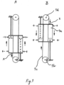
- the preferred feeding system for a dry ice blasting machine has:
- Guide rods may be desired in cases where the cylinder(s) do not offer sufficient guidance by themselves.
- Guide rod ends can be fixed in either end in base blocks (1e).
- the base blocks can also be the base for the drive axle / shaft and the idler axle / shaft and for the cylinder piston rod ends directly or indirectly.
- the base blocks can be made of steel, aluminium or other metals, plastic materials or composite materials.
- the base blocks can be positioned between a set of pulleys drive axle respectively idler axle but other positions are also possible.
- the drive axle naturally rotates, whereas the idler axle need not be rotating.
- the idler axis can directly or indirectly, for instance through an insulating block, be attached to the hopper.
- the drive shaft is attached to the hopper with a bearing / bushing block which ensures a low friction rotation at very low temperatures down to -78°C.
- the bearing bushing block can be made of steel, stainless steel, plastic materials, composite materials, ceramics or similar.
- Two drive pulleys (1b) with two built-in one way clutches on the same axle The one way clutches are mounted so they engage in the same rotary direction. They are supported by other bearings or bushings to relief the radial and axial loads.
- the resulting torque on the output shaft is determined from the total piston area, the pressure in the cylinders and the radial distance from the shaft center to where the chain engages the pulley.
- the pulleys can be made of steel, aluminium, other metals, plastic, composite materials or similar.
- the chains or similar (1c) which are attached to the cylinder on each side of an axis drawn between idler axle and drive shaft.
- the chains or similar are not required to be the same material or shape in the entire length. They can for instance be a chain, timing belt or v-belt for the part engaging in the drive pulley and a wire rope for the part running on the idler pulley.
- the pulleys can be made of steel, aluminium, other metals, plastic, composite materials or similar. They must naturally be designed according to the chain, timing belt, v-belt, wire they are in contact with.
- the pneumatic cylinders move by gas, compressed air or similar. Piston rod ends remain fixed to the frame.
- the fluid for moving the cylinders may first pass a filter and a pressure relief valve.
- a pneumatic circuit designed for activating the cylinders includes valves letting fluid in on one side of the piston and thereby moving the cylinder. Speed is adjusted by a flow control valve controlling the flow out of the opposite piston side. When the cylinder reaches the end position a mechanically operated sensor valve or a logic valve element reverses the flow so former outlet becomes inlet, and former inlet becomes outlet. As result the cylinder movement is also reversed.
- the chains / timing belts or similar (1c) attached to the pneumatic cylinders move together with the cylinders.
- the chains are (as indicated with "x" in fig. 1 ) attached to the cylinders on left and right, respectively, side relative to the pulley(s). This makes it possible to pull on the one and same side of the drive pulleys regardless of the moving direction of the pneumatic cylinders.
- the other pulley will rotate freely because it is being pulled opposite to the engagement direction of the one-way clutch/one-way bearing built into it.
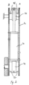
- the hopper is made with 3 straight and ideally vertical sides and the long side >150mm.
- the sides preferably are strong or reinforced at least the edges so they do not give in to thermal contraction. Making the 2 opposing straight sides rectangular eases the attachment of the hopper to other body parts and the attachment of components to the hopper.
- the auger is floating in/at the bottom of the hopper and in the outlet pipe where it enters approximately one flight.
- the hopper preferably is insulating or covered with insulating material like Rockwool, plastic foam, ceramic insulation, vacuum insulation or similar.
- the inclined side preferably has an angle with horizontal of at least 25°.
- the sides may be made of steel coated, galvanized, powder coated or stainless steel or other metals, plastic materials such as pvc, polyurethane, polyethylene or other or plywood, fiberboard or composite materials.
- the hopper can be designed of individual parts joined together by fasteners, welding, gluing, soldering or similar or it can be cast / molded in one piece.
- the outlet part for the dry ice can be made of the above mentioned materials and attached to the hopper or the outlet can be cast I molded as an integral part of the hopper. Preferably it is also insulated if not made by an insulating material.
- Auger connected to the drive 1) and feeding the dry ice out of the hopper.
- the pulleys drive an axle / drive shaft with an auger attached.
- the axle can be made of steel, stainless steel, other metals, plastics, composite materials or ceramics.
- the attachment between the drive axle and the auger only prevents the two parts from rotating relative to each other. For instance by a half moon, square, hexagonal, key-way designed cross section capable of transferring the torque. The axial direction is not locked, so easy dismantling without tools of the auger is possible.
- the end of the hollow drive shaft is inserted into the auger end in order to minimize cold transfer to the bearings, but vice versa is also possible
- the auger is made with a uniform outer diameter and a conical internal diameter decreasing from opposite the outlet towards the outlet.
- the shaft is formed as the internal diameter until the internal diameter is continuous straight.
- the last part of the auger where the internal diameter is straight is left shaft-less.
- the auger can be with or without a shaft in full or in part.
- a shaft can be straight or conical, solid or hollow. It can be made of steel, coated or not coated, stainless steel, other metals, plastic materials, composite materials, ceramics.
- the flights are helical turning left or right and typical with a rectangular or trapezoidal cross section.
- the helical flights can be made of steel, coated or not coated, stainless steel, other metals, plastic materials, composite materials, ceramic.
- the entire auger made up of the shaft and the flights can be made of the same material but they can also be made of different materials for instance a steel shaft with plastic flights. Metal parts for augers can be cast or pressed.
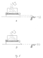
- Fig 5 From the outlet pipe the entrained material is transferred to the nozzle in a vacuum hose separated from the fluid hose in a dual hose (A). Alternatively the entrained material is transferred to the nozzle in a single hose (B).
Landscapes
- Engineering & Computer Science (AREA)
- Mechanical Engineering (AREA)
- General Engineering & Computer Science (AREA)
- Physics & Mathematics (AREA)
- Fluid Mechanics (AREA)
- Filling Or Emptying Of Bunkers, Hoppers, And Tanks (AREA)
- Screw Conveyors (AREA)
Claims (10)
- Vorrichtung zur Ausgabe eines festen Materials, wobei die Vorrichtung umfasst:- einen Behälter zum Aufnehmen des festen Materials,- einen ersten Eingang für das Gas,- einen Ausgang für festes Material,- eine drehbare Förderschnecke zum Transportieren des festen Materials vom Behälter zum Ausgang,- einen Spender, der dazu konfiguriert ist, das feste Material vom Ausgang aufzunehmen und das erste Gas vom ersten Eingang zu empfangen und das im ersten Gas mitgeführte feste Material auszugeben, und- einen Motor, der zum Drehen der Schnecke konfiguriert ist,wobei der Motor umfasst:- einem oder mehrere Zylinder (1a), die jeweils einen Kolben aufweisen, und- einen zweiten Eingang für ein Fluid und Elemente zum Zuführen des Flüssigkeit vom zweiten Eingang zum die genannten einen oder die mehreren Zylinder (1a),dadurch gekennzeichnet, dass:- Der Motor umfasst einen Antrieb, der so konfiguriert ist, dass er die Bewegung des Kolbens/der Kolben umwandelt in Rotation der Schnecke,- der Feststoff ist auf unter -10°C gefrorenes Trockeneis und- der Querschnitt von mindestens einem der Kolben mindestens 700 mm 2 beträgt.
- Die Vorrichtung nach einem der vorhergehenden Ansprüche, die zusätzlich einen Schlauch oder eine Röhre umfasst
die an einem Ende mit dem Ausgang verbunden ist und ein zweites Ende hat und so konfiguriert ist, dass sie den Trockeneisausgang des Ausgangs aufnimmt und dem Spender zuführt. - Die Vorrichtung nach Anspruch 2, die außerdem ein Element zur Erzeugung eines Flusses von eine zweite Flüssigkeit in der Röhre oder dem Schlauch in einer Richtung weg vom Ausgang.
- Vorrichtung nach Anspruch 2, wobei der Spender mit dem Röhre oder Schlauch verbunden ist und ist so konfiguriert, dass es einen Strom einer dritten Flüssigkeit aufnimmt, wobei das Ausgangselement ein Venturi-Element umfasst, das so konfiguriert ist, dass es durch Saugen in der Röhre oder dem Schlauch einen zweiten Strom in der Röhre oder dem Schlauch in einer Richtung weg von dem Ausgang erzeugt.
- Vorrichtung nach einem der vorhergehenden Ansprüche, wobei der zweite Eingang so konfiguriert ist, dass er den Teil der Flüssigkeit intermittierend auf gegenüberliegenden Seiten jedes Kolbens zuführt.
- Verfahren zum Betreiben der Vorrichtung nach Anspruch 1, wobei das Verfahren umfasst:- Bereitstellen des Trockeneises im Behälter,- Zuführen des Flüssigkeit zum zweiten Eingang,- Antreiben der Schnecke zum Transport des Trockeneises vom Behälter zum Ausgang,- Ausgeben des Trockeneises durch den Ausgang,wobei der Antriebsschritt das Zuführen eines Teils des Gases zum zweiten Eingang umfasst, um einen Teil des Gases den Zylindern zuzuführen, undwobei der Ausgabeschritt den Schritt des Mitreißens des ausgegebenen Trockeneises im ersten Gas umfasst.
- Das Verfahren nach einem der Ansprüche 6 , das außerdem den Schritt des Transports des Trockeneisausstoßes des Ausgangs in einem Schlauch oder einer Röhre umfasst, der/die an einem Ende mit dem Ausgang verbunden ist und ein zweites Ende hat.
- Das Verfahren nach Anspruch 7, das außerdem den Schritt des Erzeugens einer Strömung eines zweiten Flüssigkeit in der Röhre oder dem Schlauch in eine vom Ausgang wegführende Richtung umfasst.
- Das Verfahren nach Anspruch 7, das außerdem die Zuführung eines Stroms eines dritten Flüssigkeit zu einem Venturi-Element umfasst, das mit dem Schlauch/ Röhre verbunden ist, um einen zweiten Strom in dem Schlauch oder Röhre in einer Richtung weg vom Ausgang zu erzeugen.
- Das Verfahren nach einem der Ansprüche 6 bis 9, wobei der Antriebsschritt das intermittierende Zuführen des Teils der Flüssigkeit auf gegenüberliegende Seiten jedes Kolbens umfasst.
Applications Claiming Priority (2)
| Application Number | Priority Date | Filing Date | Title |
|---|---|---|---|
| DKPA201600187 | 2016-03-28 | ||
| PCT/DK2017/000004 WO2017167334A1 (en) | 2016-03-28 | 2017-03-27 | An apparatus for outputting a solid material, such as entrained in a fluid |
Publications (4)
| Publication Number | Publication Date |
|---|---|
| EP3436720A1 EP3436720A1 (de) | 2019-02-06 |
| EP3436720A4 EP3436720A4 (de) | 2019-11-27 |
| EP3436720B1 true EP3436720B1 (de) | 2024-08-07 |
| EP3436720C0 EP3436720C0 (de) | 2024-08-07 |
Family
ID=59962634
Family Applications (1)
| Application Number | Title | Priority Date | Filing Date |
|---|---|---|---|
| EP17773346.6A Active EP3436720B1 (de) | 2016-03-28 | 2017-03-27 | Vorrichtung zur ausgabe eines in einer flüssigkeit mitgeführten festen materials und verfahren zum betrieb desselben |
Country Status (4)
| Country | Link |
|---|---|
| US (1) | US10844881B2 (de) |
| EP (1) | EP3436720B1 (de) |
| CN (1) | CN109477559B (de) |
| WO (1) | WO2017167334A1 (de) |
Families Citing this family (10)
| Publication number | Priority date | Publication date | Assignee | Title |
|---|---|---|---|---|
| JP7577747B2 (ja) | 2019-12-31 | 2024-11-05 | コールド・ジェット・エルエルシー | ブラストストリームを強化する方法および装置 |
| US11167930B1 (en) * | 2020-04-23 | 2021-11-09 | Brent Stanley Bradford | Auger conveyor for removing unwanted contaminants from a granular material |
| JP7503835B2 (ja) * | 2020-09-17 | 2024-06-21 | 東京精密発條株式会社 | スパイラルコンベアおよびフィルターユニット |
| US11746860B2 (en) * | 2020-12-23 | 2023-09-05 | Liftwave, Inc. | Self-reeling belt drive |
| WO2022140374A1 (en) | 2020-12-23 | 2022-06-30 | Liftwave, Inc. Dba Rise Robotics | Self-reeling belt drive mechanism |
| CN116997708A (zh) * | 2021-01-19 | 2023-11-03 | 托汉萨有限责任公司 | 构建于二冲程十字头发动机中用于污泥清理的自动清理系统 |
| CN113753506B (zh) * | 2021-06-23 | 2023-03-28 | 山东华鲁恒升化工股份有限公司 | 化工原料向上输送装置 |
| KR20250037406A (ko) * | 2022-07-11 | 2025-03-17 | 네스테 오와이제이 | 가스 배관 시스템, 장치, 가스 배관 시스템의 용도, 및 가스 배관 시스템의 작동 방법 |
| EP4306209A1 (de) * | 2022-07-11 | 2024-01-17 | Neste Oyj | Gasrohrleitungssystem, anordnung, verwendung des gasrohrleitungssystems und verfahren zum betreiben eines gasrohrleitungssystems |
| US20240208741A1 (en) * | 2022-12-21 | 2024-06-27 | NA Pacific | Modular spreader device kit and method of assembly |
Family Cites Families (40)
| Publication number | Priority date | Publication date | Assignee | Title |
|---|---|---|---|---|
| FR1275167A (fr) * | 1960-11-25 | 1961-11-03 | Système de transformation d'un mouvement rectiligne alternatif en mouvement circulaire continu | |
| SE384908B (sv) * | 1974-04-18 | 1976-05-24 | Hammars Mekaniska Verkstad Ab | Sett och anordning for att driva en axel i en jemn, kontinuerlig rotation |
| US4363571A (en) * | 1980-04-04 | 1982-12-14 | United Conveyor Corporation | System for feeding pulverulent material into a pressurized air conveyor pipeline |
| FR2522626A1 (fr) * | 1982-03-02 | 1983-09-09 | Morillon Ets | Dispositif d'assistance au demarrage d'extracteur a vis equipant des cellules de stockage de produits pulverulents ou granuleux |
| CH657600A5 (de) * | 1982-06-04 | 1986-09-15 | Buehler Ag Geb | Foerderanlage. |
| DE3546276A1 (de) * | 1985-12-28 | 1986-04-30 | Joachim 7580 Bühl Rühlemann | Getriebe zur umwandlung einer oszillierenden translations- oder rotationsbewegung in eine kontinuierliche rotationsbewegung |
| DE8702594U1 (de) * | 1987-02-20 | 1987-06-19 | Nabavinegad, Irene, 8724 Mainberg | Getriebe zur Übertragung zweier translatorischer Kräfte auf eine Abtriebswelle |
| US4820375A (en) * | 1987-11-16 | 1989-04-11 | Condes Corporation | Screw type rod feeding and placement mechanism |
| IT1224364B (it) * | 1988-05-11 | 1990-10-04 | Trasportatori Govoni Srl | Metodo, macchina e impianto per l'evacuazione, il convogliamento, la compattazione e lo scarico di materiali sfusi, in particolare trucioli e sfridi |
| US5511925A (en) * | 1993-01-07 | 1996-04-30 | Muth; Gordon E. | Bin unloading apparatus |
| US5333762A (en) * | 1993-05-07 | 1994-08-02 | Hyer Industries, Inc. | Screw feeder with progressively decreasing screw confinement |
| US5562010A (en) * | 1993-12-13 | 1996-10-08 | Mcguire; Bernard | Reversing drive |
| DE19517582C2 (de) * | 1995-05-05 | 1998-08-20 | Mannesmann Ag | Antrieb für die Einspritz- und Plastifiziereinheit einer Kunststoffspritzgießmaschine |
| US5871619A (en) * | 1995-09-14 | 1999-02-16 | Tire Recycling Technologies Corporation | Plug seal discharge system for distillation apparatus |
| JP2000185339A (ja) * | 1998-12-22 | 2000-07-04 | Toshiba Mach Co Ltd | 電動式射出成形機の駆動装置 |
| TW521031B (en) * | 2001-04-27 | 2003-02-21 | Mitsubishi Heavy Ind Ltd | Ball screw device and injection molding machine incorporating the same |
| JP4329058B2 (ja) * | 2001-06-21 | 2009-09-09 | 新東工業株式会社 | 混練砂の搬送スクリュ−コンベヤ装置の制御方法 |
| AU2003900362A0 (en) * | 2003-01-29 | 2003-02-13 | Wm Olds And Sons Pty Ltd | Screw conveyor |
| US7004305B2 (en) * | 2004-02-19 | 2006-02-28 | The Gsi Group, Inc. | Easily assemblable grain bin sweep |
| US7390118B2 (en) * | 2004-10-15 | 2008-06-24 | Husky Injection Molding Systems Ltd. | Extruder assembly |
| US7381131B1 (en) * | 2006-07-19 | 2008-06-03 | Harpole Danny J | Extendable auger conveyor |
| DE202009014265U1 (de) * | 2009-10-21 | 2009-12-31 | Eugster/Frismag Ag | Instantpulverfördervorrichtung eines Getränkezubereitungsgeräts |
| KR101041093B1 (ko) * | 2010-03-31 | 2011-06-14 | 한국기계연구원 | 유체 실린더 구동식 모터와 유체 실린더 구동식 수직회전 모터 |
| US8353394B2 (en) * | 2011-02-09 | 2013-01-15 | Atomic Energy Council—Institue of Nuclear Energy Research | Continuous constant-rate feeding system |
| US9650217B1 (en) * | 2011-04-22 | 2017-05-16 | Sudenga Industries, Inc. | Bin sweep with weight-sensitive link |
| JP5641438B2 (ja) * | 2011-08-01 | 2014-12-17 | 株式会社ダイフク | スクリュー駆動エリアへの搬送台車送込み装置 |
| JP6088728B2 (ja) * | 2011-09-27 | 2017-03-01 | 株式会社松井製作所 | 粉粒体材料の供給装置、及びこれを備えた粉粒体材料の配合供給装置 |
| JP5673482B2 (ja) * | 2011-10-19 | 2015-02-18 | 株式会社豊田自動織機 | 射出装置 |
| AT512170B1 (de) * | 2012-02-28 | 2013-06-15 | Bsw Machinery Handels Gmbh | Vorrichtung zum Zuführen von Granulat und Füllmaterial zu einer Extruderschnecke eines Extruders |
| US9033643B1 (en) * | 2012-03-13 | 2015-05-19 | Ronald J. Kile | Combine harvester grain bulk tank unloading system |
| JP5822813B2 (ja) * | 2012-10-15 | 2015-11-24 | ホンダ太陽株式会社 | ワーク送出装置 |
| US10364394B2 (en) * | 2013-10-29 | 2019-07-30 | The Crucible Group Pty Ltd | Converter for organic materials |
| US9321597B2 (en) * | 2013-12-24 | 2016-04-26 | Morrison Timing Screw Co. | Feeding mechanism and method |
| US9376262B2 (en) * | 2014-05-30 | 2016-06-28 | Douglas Kent Schroeder | Separated drive and sealing device for screw conveyor |
| CN204096505U (zh) * | 2014-08-31 | 2015-01-14 | 三一重型能源装备有限公司 | 螺旋输砂装置及具有该螺旋输砂装置的混砂车 |
| CA2999765C (en) * | 2015-09-24 | 2022-06-21 | Olds Elevator, Llc | Pressure sealed high temperature elevating conveyor |
| US9950872B2 (en) * | 2015-11-30 | 2018-04-24 | Superior Manufacturing LLC | Bin sweep auger unplugging system |
| WO2017117147A2 (en) * | 2015-12-29 | 2017-07-06 | Lighthouse Instruments, Llc. | Concentric shaft split timing screw system |
| US9643787B1 (en) * | 2016-06-10 | 2017-05-09 | Brandt Agricultural Products Ltd. | Auger transfer conveyor |
| US10421617B2 (en) * | 2017-06-29 | 2019-09-24 | Mark E Koenig | Cantilevered screw assembly with speed reducer and pivoting torque arm |
-
2017
- 2017-03-27 WO PCT/DK2017/000004 patent/WO2017167334A1/en not_active Ceased
- 2017-03-27 US US16/088,339 patent/US10844881B2/en active Active
- 2017-03-27 EP EP17773346.6A patent/EP3436720B1/de active Active
- 2017-03-27 CN CN201780020856.7A patent/CN109477559B/zh active Active
Also Published As
| Publication number | Publication date |
|---|---|
| CN109477559A (zh) | 2019-03-15 |
| US20190113055A1 (en) | 2019-04-18 |
| EP3436720A1 (de) | 2019-02-06 |
| WO2017167334A1 (en) | 2017-10-05 |
| EP3436720A4 (de) | 2019-11-27 |
| EP3436720C0 (de) | 2024-08-07 |
| CN109477559B (zh) | 2022-07-12 |
| US10844881B2 (en) | 2020-11-24 |
Similar Documents
| Publication | Publication Date | Title |
|---|---|---|
| EP3436720B1 (de) | Vorrichtung zur ausgabe eines in einer flüssigkeit mitgeführten festen materials und verfahren zum betrieb desselben | |
| MXPA97007823A (en) | Equipment for the processing of synthetic articles termoplasti | |
| US5558473A (en) | Labyrinth seal coal injector | |
| US10717612B2 (en) | System for conveying pasty material | |
| CN1200097A (zh) | 螺旋推运器的驱动装置和方法 | |
| EP0314752A1 (de) | Fördervorrichtung. | |
| CN212739890U (zh) | 可曲挠圆管螺旋输送设备 | |
| CN107826274B (zh) | 一种螺旋气力复合式输送粉体装料设备 | |
| CN106241231A (zh) | 强吸力螺旋输送器 | |
| FI125741B (fi) | Menetelmä ja laitteisto materiaalin käsittelemiseksi pneumaattisessa materiaalinkäsittelyjärjestelmässä | |
| US5839883A (en) | System and method for controlling a materials handling system | |
| CN211732816U (zh) | 一种螺旋输送机 | |
| HK40004781A (en) | An apparatus for outputting a solid material, such as entrained in a fluid | |
| HK40004781B (en) | An apparatus for outputting a solid material, such as entrained in a fluid | |
| CN206939709U (zh) | 组合式污泥螺旋输送装置 | |
| CN202668799U (zh) | 吹瓶机把手整理输送机构 | |
| US20150104580A1 (en) | System for applying viscous substances | |
| HU208364B (en) | Pump operated on volumetric principle | |
| CN114380074B (zh) | 料箱、无人装置和加料方法 | |
| CN108790103B (zh) | Pe木塑复合材料的加工设备 | |
| CN209521135U (zh) | 一种橡塑密炼机气力输送装置 | |
| US20050189199A1 (en) | Archimedean conveyors and combustion engines | |
| CN114852605A (zh) | 一种多出料口螺旋输送机 | |
| US7418829B2 (en) | Apparatus for the production of ice-cream mass with solid ingredients | |
| CN216188469U (zh) | 一种防脱链管链机链轮箱 |
Legal Events
| Date | Code | Title | Description |
|---|---|---|---|
| STAA | Information on the status of an ep patent application or granted ep patent |
Free format text: STATUS: THE INTERNATIONAL PUBLICATION HAS BEEN MADE |
|
| PUAI | Public reference made under article 153(3) epc to a published international application that has entered the european phase |
Free format text: ORIGINAL CODE: 0009012 |
|
| STAA | Information on the status of an ep patent application or granted ep patent |
Free format text: STATUS: REQUEST FOR EXAMINATION WAS MADE |
|
| 17P | Request for examination filed |
Effective date: 20181029 |
|
| AK | Designated contracting states |
Kind code of ref document: A1 Designated state(s): AL AT BE BG CH CY CZ DE DK EE ES FI FR GB GR HR HU IE IS IT LI LT LU LV MC MK MT NL NO PL PT RO RS SE SI SK SM TR |
|
| AX | Request for extension of the european patent |
Extension state: BA ME |
|
| DAV | Request for validation of the european patent (deleted) | ||
| DAX | Request for extension of the european patent (deleted) | ||
| A4 | Supplementary search report drawn up and despatched |
Effective date: 20191024 |
|
| RIC1 | Information provided on ipc code assigned before grant |
Ipc: B65G 33/08 20060101ALI20191018BHEP Ipc: F16H 19/02 20060101AFI20191018BHEP |
|
| STAA | Information on the status of an ep patent application or granted ep patent |
Free format text: STATUS: EXAMINATION IS IN PROGRESS |
|
| 17Q | First examination report despatched |
Effective date: 20211022 |
|
| GRAP | Despatch of communication of intention to grant a patent |
Free format text: ORIGINAL CODE: EPIDOSNIGR1 |
|
| STAA | Information on the status of an ep patent application or granted ep patent |
Free format text: STATUS: GRANT OF PATENT IS INTENDED |
|
| INTG | Intention to grant announced |
Effective date: 20240306 |
|
| GRAS | Grant fee paid |
Free format text: ORIGINAL CODE: EPIDOSNIGR3 |
|
| GRAA | (expected) grant |
Free format text: ORIGINAL CODE: 0009210 |
|
| STAA | Information on the status of an ep patent application or granted ep patent |
Free format text: STATUS: THE PATENT HAS BEEN GRANTED |
|
| AK | Designated contracting states |
Kind code of ref document: B1 Designated state(s): AL AT BE BG CH CY CZ DE DK EE ES FI FR GB GR HR HU IE IS IT LI LT LU LV MC MK MT NL NO PL PT RO RS SE SI SK SM TR |
|
| REG | Reference to a national code |
Ref country code: GB Ref legal event code: FG4D |
|
| REG | Reference to a national code |
Ref country code: CH Ref legal event code: EP |
|
| REG | Reference to a national code |
Ref country code: DE Ref legal event code: R096 Ref document number: 602017083909 Country of ref document: DE |
|
| REG | Reference to a national code |
Ref country code: IE Ref legal event code: FG4D |
|
| U01 | Request for unitary effect filed |
Effective date: 20240903 |
|
| U07 | Unitary effect registered |
Designated state(s): AT BE BG DE DK EE FI FR IT LT LU LV MT NL PT RO SE SI Effective date: 20240918 |
|
| PG25 | Lapsed in a contracting state [announced via postgrant information from national office to epo] |
Ref country code: NO Free format text: LAPSE BECAUSE OF FAILURE TO SUBMIT A TRANSLATION OF THE DESCRIPTION OR TO PAY THE FEE WITHIN THE PRESCRIBED TIME-LIMIT Effective date: 20241107 |
|
| PG25 | Lapsed in a contracting state [announced via postgrant information from national office to epo] |
Ref country code: GR Free format text: LAPSE BECAUSE OF FAILURE TO SUBMIT A TRANSLATION OF THE DESCRIPTION OR TO PAY THE FEE WITHIN THE PRESCRIBED TIME-LIMIT Effective date: 20241108 Ref country code: PL Free format text: LAPSE BECAUSE OF FAILURE TO SUBMIT A TRANSLATION OF THE DESCRIPTION OR TO PAY THE FEE WITHIN THE PRESCRIBED TIME-LIMIT Effective date: 20240807 |
|
| PG25 | Lapsed in a contracting state [announced via postgrant information from national office to epo] |
Ref country code: IS Free format text: LAPSE BECAUSE OF FAILURE TO SUBMIT A TRANSLATION OF THE DESCRIPTION OR TO PAY THE FEE WITHIN THE PRESCRIBED TIME-LIMIT Effective date: 20241207 |
|
| PG25 | Lapsed in a contracting state [announced via postgrant information from national office to epo] |
Ref country code: HR Free format text: LAPSE BECAUSE OF FAILURE TO SUBMIT A TRANSLATION OF THE DESCRIPTION OR TO PAY THE FEE WITHIN THE PRESCRIBED TIME-LIMIT Effective date: 20240807 |
|
| PG25 | Lapsed in a contracting state [announced via postgrant information from national office to epo] |
Ref country code: RS Free format text: LAPSE BECAUSE OF FAILURE TO SUBMIT A TRANSLATION OF THE DESCRIPTION OR TO PAY THE FEE WITHIN THE PRESCRIBED TIME-LIMIT Effective date: 20241107 Ref country code: ES Free format text: LAPSE BECAUSE OF FAILURE TO SUBMIT A TRANSLATION OF THE DESCRIPTION OR TO PAY THE FEE WITHIN THE PRESCRIBED TIME-LIMIT Effective date: 20240807 |
|
| PG25 | Lapsed in a contracting state [announced via postgrant information from national office to epo] |
Ref country code: RS Free format text: LAPSE BECAUSE OF FAILURE TO SUBMIT A TRANSLATION OF THE DESCRIPTION OR TO PAY THE FEE WITHIN THE PRESCRIBED TIME-LIMIT Effective date: 20241107 Ref country code: PL Free format text: LAPSE BECAUSE OF FAILURE TO SUBMIT A TRANSLATION OF THE DESCRIPTION OR TO PAY THE FEE WITHIN THE PRESCRIBED TIME-LIMIT Effective date: 20240807 Ref country code: NO Free format text: LAPSE BECAUSE OF FAILURE TO SUBMIT A TRANSLATION OF THE DESCRIPTION OR TO PAY THE FEE WITHIN THE PRESCRIBED TIME-LIMIT Effective date: 20241107 Ref country code: IS Free format text: LAPSE BECAUSE OF FAILURE TO SUBMIT A TRANSLATION OF THE DESCRIPTION OR TO PAY THE FEE WITHIN THE PRESCRIBED TIME-LIMIT Effective date: 20241207 Ref country code: HR Free format text: LAPSE BECAUSE OF FAILURE TO SUBMIT A TRANSLATION OF THE DESCRIPTION OR TO PAY THE FEE WITHIN THE PRESCRIBED TIME-LIMIT Effective date: 20240807 Ref country code: GR Free format text: LAPSE BECAUSE OF FAILURE TO SUBMIT A TRANSLATION OF THE DESCRIPTION OR TO PAY THE FEE WITHIN THE PRESCRIBED TIME-LIMIT Effective date: 20241108 Ref country code: ES Free format text: LAPSE BECAUSE OF FAILURE TO SUBMIT A TRANSLATION OF THE DESCRIPTION OR TO PAY THE FEE WITHIN THE PRESCRIBED TIME-LIMIT Effective date: 20240807 |
|
| PG25 | Lapsed in a contracting state [announced via postgrant information from national office to epo] |
Ref country code: SM Free format text: LAPSE BECAUSE OF FAILURE TO SUBMIT A TRANSLATION OF THE DESCRIPTION OR TO PAY THE FEE WITHIN THE PRESCRIBED TIME-LIMIT Effective date: 20240807 |
|
| U20 | Renewal fee for the european patent with unitary effect paid |
Year of fee payment: 9 Effective date: 20250310 |
|
| PG25 | Lapsed in a contracting state [announced via postgrant information from national office to epo] |
Ref country code: CZ Free format text: LAPSE BECAUSE OF FAILURE TO SUBMIT A TRANSLATION OF THE DESCRIPTION OR TO PAY THE FEE WITHIN THE PRESCRIBED TIME-LIMIT Effective date: 20240807 |
|
| PG25 | Lapsed in a contracting state [announced via postgrant information from national office to epo] |
Ref country code: SK Free format text: LAPSE BECAUSE OF FAILURE TO SUBMIT A TRANSLATION OF THE DESCRIPTION OR TO PAY THE FEE WITHIN THE PRESCRIBED TIME-LIMIT Effective date: 20240807 |
|
| PGFP | Annual fee paid to national office [announced via postgrant information from national office to epo] |
Ref country code: GB Payment date: 20250310 Year of fee payment: 9 |
|
| PLBE | No opposition filed within time limit |
Free format text: ORIGINAL CODE: 0009261 |
|
| STAA | Information on the status of an ep patent application or granted ep patent |
Free format text: STATUS: NO OPPOSITION FILED WITHIN TIME LIMIT |
|
| 26N | No opposition filed |
Effective date: 20250508 |
|
| PG25 | Lapsed in a contracting state [announced via postgrant information from national office to epo] |
Ref country code: MC Free format text: LAPSE BECAUSE OF FAILURE TO SUBMIT A TRANSLATION OF THE DESCRIPTION OR TO PAY THE FEE WITHIN THE PRESCRIBED TIME-LIMIT Effective date: 20240807 |
|
| REG | Reference to a national code |
Ref country code: CH Ref legal event code: H13 Free format text: ST27 STATUS EVENT CODE: U-0-0-H10-H13 (AS PROVIDED BY THE NATIONAL OFFICE) Effective date: 20251023 |