EP3434138B1 - Elektrisch faltbarer und entfaltbarer mehrfaltenschirm - Google Patents
Elektrisch faltbarer und entfaltbarer mehrfaltenschirm Download PDFInfo
- Publication number
- EP3434138B1 EP3434138B1 EP17769291.0A EP17769291A EP3434138B1 EP 3434138 B1 EP3434138 B1 EP 3434138B1 EP 17769291 A EP17769291 A EP 17769291A EP 3434138 B1 EP3434138 B1 EP 3434138B1
- Authority
- EP
- European Patent Office
- Prior art keywords
- button
- handle
- unfolding
- pulley
- folding
- Prior art date
- Legal status (The legal status is an assumption and is not a legal conclusion. Google has not performed a legal analysis and makes no representation as to the accuracy of the status listed.)
- Active
Links
Images


Classifications
-
- A—HUMAN NECESSITIES
- A45—HAND OR TRAVELLING ARTICLES
- A45B—WALKING STICKS; UMBRELLAS; LADIES' OR LIKE FANS
- A45B25/00—Details of umbrellas
- A45B25/14—Devices for opening and for closing umbrellas
- A45B25/143—Devices for opening and for closing umbrellas automatic
-
- A—HUMAN NECESSITIES
- A45—HAND OR TRAVELLING ARTICLES
- A45B—WALKING STICKS; UMBRELLAS; LADIES' OR LIKE FANS
- A45B25/00—Details of umbrellas
- A45B25/14—Devices for opening and for closing umbrellas
-
- A—HUMAN NECESSITIES
- A45—HAND OR TRAVELLING ARTICLES
- A45B—WALKING STICKS; UMBRELLAS; LADIES' OR LIKE FANS
- A45B19/00—Special folding or telescoping of umbrellas
- A45B19/04—Special folding or telescoping of umbrellas with telescopic sticks
-
- A—HUMAN NECESSITIES
- A45—HAND OR TRAVELLING ARTICLES
- A45B—WALKING STICKS; UMBRELLAS; LADIES' OR LIKE FANS
- A45B19/00—Special folding or telescoping of umbrellas
- A45B19/10—Special folding or telescoping of umbrellas with collapsible ribs
-
- H—ELECTRICITY
- H01—ELECTRIC ELEMENTS
- H01H—ELECTRIC SWITCHES; RELAYS; SELECTORS; EMERGENCY PROTECTIVE DEVICES
- H01H13/00—Switches having rectilinearly-movable operating part or parts adapted for pushing or pulling in one direction only, e.g. push-button switch
- H01H13/02—Details
- H01H13/12—Movable parts; Contacts mounted thereon
- H01H13/14—Operating parts, e.g. push-button
-
- A—HUMAN NECESSITIES
- A45—HAND OR TRAVELLING ARTICLES
- A45B—WALKING STICKS; UMBRELLAS; LADIES' OR LIKE FANS
- A45B25/00—Details of umbrellas
- A45B25/14—Devices for opening and for closing umbrellas
- A45B2025/146—Devices for opening and for closing umbrellas with a crank connected to a rope
-
- A—HUMAN NECESSITIES
- A45—HAND OR TRAVELLING ARTICLES
- A45B—WALKING STICKS; UMBRELLAS; LADIES' OR LIKE FANS
- A45B25/00—Details of umbrellas
- A45B25/16—Automatic openers, e.g. frames with spring mechanisms
- A45B25/165—Automatic openers, e.g. frames with spring mechanisms with fluid or electric actuators
Definitions
- the disclosure generally relates to the technical field of umbrella, and more particularly relates to an electrically folding and unfolding multi-fold umbrella.
- Umbrellas are necessary in peoples' daily lives. People has put a lot of effort on the researching of umbrellas, and has developed manual umbrellas, automatic umbrellas, and electrically folding and unfolding multi-fold umbrellas. Currently, for the electrically folding and unfolding umbrella in the market, the motor of the umbrella is normally defined in the umbrella's handle, resulting in that the umbrella is overlong, which is inconvenient for people to use and carry.
- An example of an automatically opening and closing umbrella is disclosed in CN 202496557U .
- the electrically folding and unfolding multi-fold umbrella includes a handle, a pull cord, and an intermediate shaft fixedly connected with the handle, the handle is defined at one end of the intermediate shaft, an upper nest and a lower nest are defined at two sides of the intermediate shaft respectively, and the lower nest is adjacent to the handle, a motor, a first gear, and at least one pulley are all located in the upper nest, the first gear is coaxial with one pulley, a side of the motor adjacent to the handle defines a lead screw which is engaged with the first gear, an axis of the pulley is connected to an inner surface of the upper nest, a fixed pulley is defined at a side of an inner surface of the lower nest, one end of the pull cord is fixed in the end of the intermediate shaft adjacent to the handle, the other end of the pull cord is fixed on the upper nest after steering by the pulley in the upper nest and the fixed pulley in the lower nest in sequence.
- axes of the three pulleys are all connected to the inner surface of the upper nest, the pull cord steers by the three pulleys in sequence.
- axes of the three pulleys are all connected to the inner surface of the upper nest, a side of each of the pulleys back to the lead screw defines a second gear, and each two adjacent second gears are engaged with each other, each of the second gears is coaxial with one corresponding pulley, the pull cord steers by the pulleys in sequence.
- a battery, an electric wire, and a switch component are located in the handle, the switch component is connected with the battery through the electric wire, a spring and a spring type wire are defined in the intermediate shaft, the switch component is connected with the motor through the spring and the spring type wire, an outer surface of the handle defines a control button which is capable to contact with the switch component.
- control button includes an unfolding button and a folding button, orientations of the unfolding button and the folding button on the outer surface of the handle are consistent with an extending direction of the intermediate shaft.
- the battery is a rechargeable battery.
- the switch component includes a switch button, a double-pole double-throw switch, a bottom clamping portion, a button clamping portion, and a button spring
- the switch button and the button clamping portion are respectively defined at two opposite sides of a top end of the handle, two ends of the button spring respectively resist on the button clamping portion and an inner surface of the handle
- the button clamping portion is defined at the end of the intermediate shaft adjacent to the handle, and the bottom clamping portion resists on the button clamping portion
- the electric wire is respectively connected with the battery, the double-pole double-throw switch, the switch button, the spring, and the spring type wire.
- the intermediate shaft includes an outer tube, at least one intermediate tube, and an inner tube, the inner tube, the at least one intermediate tube and the outer tube are sequentially sleeved one over the other from inside to outside, the intermediate tube is capable to slide relative to the inner tube, and the outer tube is capable to slide relative to the intermediate tube.
- the handle is fixed at one end of the inner tube
- the lower nest is movably sleeved around an outer surface of the outer tube
- the upper nest is fixed at one end of the outer tube back to the handle.
- the electrically folding and unfolding multi-fold umbrella includes a first rib, a second rib, and a tension spring, one end of the first rib is connected with the upper nest, two ends of the second rib are respectively connected with a side of the lower nest and a side of the first rib adjacent to the upper nest, two ends of the tension spring are respectively connected with the first rib and the second rib.
- the first rib is a multi-fold first rib.
- the motor having the lead screw is located in the upper nest of the electrically folding and unfolding multi-fold umbrella, the motor can rotate in a forward direction, or in a backward direction, to bring the lead screw to rotate in the forward direction, or in the backward direction, as such the first gear engaged with the lead screw can also rotate in different directions, to bring the pulley coaxially defined with the first gear to rotate in different directions, the pulley rotates to bring the pull cord to move, for folding or unfolding the electrically folding and unfolding multi-fold umbrella.
- the length of the electrically folding and unfolding multi-fold umbrella of the present disclosure can be effectively reduced, which is convenient to use and carry; and the structure is much more simpler, the rotation of the pulley is much more fast, as such it is more convenient to fold and unfold the electrically folding and unfolding multi-fold umbrella.
- Table 1 Label Name Label Name 1 switch button 2 double-pole double-throw switch 3 folding button 4 electric wire 5 switch component 6, 6A upper nest 7 fixed pulley 8 lower nest 9 outer tube 10 intermediate shaft 11 intermediate tube 12 inner tube 13 bottom clamping portion 15 handle 16 battery 17 button clamping portion 18 button spring 19 unfolding button 20, 20A motor 21 first gear 22, 22A lead screw 23, 23A pulley 24A second gear 231, 231 small pulley A 232, 232 A large pulley 233, 233 A medium size pulley 30, 30A pull cord 50 spring 60 spring type wire 70 first rib 71 second rib 80 tension spring
- the descriptions, such as the "first”, the “second” in the present disclosure, can only be used for describing the aim of description, and cannot be understood as indicating or suggestting relative importance or impliedly indicating the number of the indicated technical character. Therefore, the character indicated by the "first”, the “second” can express or impliedly include at least one character.
- the technical proposal of each exemplary embodiment can be combined with each other, however the technical proposal must base on that the ordinary skill in that art can realize the technical proposal, when the combination of the technical proposals occurs contradiction or cannot realize, it should consider that the combination of the technical proposals does not existed, and is not contained in the protection scope required by the present disclosure.
- the terms “connected”, “fixed” and the like are used broadly, and for example, “fixed” can be fixed connections, detachable connections, or integral connections; may also be mechanical or electrical connections; may also be direct connections or indirect connections via intervening structures, may also be inner connecting of two elements, or interaction relationship between two elements, unless specifically limited otherwise, which can be understood by those skilled in the art according to specific situations, which can be understood by those skilled in the art according to the detail embodiment of the present disclosure.
- the present disclosure provides an electrically folding and unfolding multi-fold umbrella.
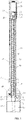
- FIG. 1 is a structure diagram of the electrically folding and unfolding multi-fold umbrella without rib in the folding state according to a first exemplary embodiment of the present disclosure
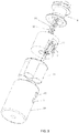
- FIG. 2 is a partial enlarged diagram of the motor and the pulley of the electrically folding and unfolding multi-fold umbrella shown in FIG. 1
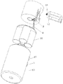
- FIG. 3 is an exploded diagram of the handle and the intermediate shaft connected with the handle of the electrically folding and unfolding multi-fold umbrella shown in FIG. 1
- FIG. 4 is a structure diagram of the electrically folding and unfolding multi-fold umbrella shown in FIG. 1
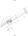
- FIG. 5 is an exploded diagram of the handle of the electrically folding and unfolding multi-fold umbrella shown in FIG. 1 .
- the electrically folding and unfolding multi-fold umbrella includes a handle 15, a pull cord 30, and an intermediate shaft 10 fixedly connected with the handle 15, the handle 15 is defined at one end of the intermediate shaft 10, an upper nest 6 and a lower nest 8 are defined at two sides of the intermediate shaft 10 respectively, and the lower nest 6 is adjacent to the handle 15, a motor 20, a first gear 21, and at least one pulley 23 are all located in the upper nest 6, the first gear 21 is coaxial with one pulley 23, a side of the motor 20 adjacent to the handle 15 defines a lead screw 22 which is engaged with the gear 21, an axis of the pulley 23 is connected to an inner surface of the upper nest 6, a fixed pulley 8 is defined at a side of an inner surface of the lower nest 8, one end of the pull cord 30 is fixed in the end of the intermediate shaft 10, the other end of the pull cord 30 is fixed on the upper nest 6 after steering by the pulley 23 in the upper nest 6 and the fixed pulley 7 in the
- the lead screw 22 defined at the side of the motor 20 can bring the first gear 21 to rotate, and further bring one pulley 23 coaxially defined with the first gear 21 to rotate in one direction, as such the pull cord 30 coiled around the pulley 23 can move along one direction, the pull cord 30 brings the lower nest 8 to move toward the upper nest 6 through the fixed pulley 7 located in the lower nest 8, as such the umbrella is unfolded; similarly, when the motor 20 rotates in a backward direction, the motor 20 brings the pulley 23 and the pull cord 30 to move in sequence through the gear 21 engaged with the lead screw 22, as such the umbrella is folded.
- the pulley 23 can further bring the pull cord 30 to move to fold or unfold the umbrella through the cooperation between the first gear 21 and the lead screw 22.
- the electrically folding and unfolding multi-fold umbrella can be fast folded and unfolded, as such the using of the electrically folding and unfolding multi-fold umbrella is much more easier and faster.
- the pulleys 23 includes a small pulley 231, a large pulley 232, and a medium size pulley 233, the large pulley 232 and the medium size pulley 233 are respectively defined at two sides of the small pulley 231, after one end of the pull cord 30 is fixed in the intermediate shaft 10, the other end of the pull cord 30 can steer by the large pulley 232, the small pulley 231, and the medium size pulley 233 in sequence, and then steer by the fixed pulley 7, finally can be fixed in the top end of the upper nest 6, one side of the large pulley 232 defines a first gear 21 which can be engaged with the the lead screw 22, the lead screw 22 can rotate to bring the large pulley 232 to rotate, the large pulley
- the setting of the multiple pulleys 23 can improve the frictional force between the pull cord 30 and the pulleys 23, to avoid the pull cord 30 from slipping on the pulleys 23, resulting in a strong cooperation between the pulleys 23 and the pull cord 30.
- a battery 16, an electric wire 4, and a switch component 5 are all located in the handle 15, the switch component 5 is connected with the battery 16 through the electric wire 4, a spring 50 and a spring type wire 60 are both located in the intermediate shaft 10, the switch component 5 is connected with the motor 20 through the spring 50 and the spring type wire 60, an outer surface of the handle 15 defines a control button (not shown) which is capable to contact with the switch component 5.
- the switch component 5 includes a switch button 1, a double-pole double-throw switch 2, a bottom clamping portion 13, a button clamping portion 17, and a button spring 18, the switch button 1 and the button clamping portion 17 are respectively defined at two opposite sides of a top end of the handle 15, two ends of the button spring 18 respectively resist on the button clamping portion 17 and an inner surface of the handle 15, the button clamping portion 13 is defined at one end of the intermediate shaft 10 adjacent to the handle 15, and the bottom clamping portion 13 resists on the button clamping portion 17, the electric wire 4 is respectively connected with the battery 16, the double-pole double-throw switch 2, the switch button 1, the spring 50, and the spring type wire 60, to form a complete circuit, the motor 20 can rotate in the forward direction or the backward direction through connecting the switch button 1 and the double-pole double-throw switch 2 with the anode or cathode of the battery 16, and the electrical conductivities of the spring 50 and the spring type wire 60; in addition, the button clamping portion 17 can move towards the inner surface of the handle
- control button (not shown) includes an unfolding button 19 and a folding button 3, in the exemplary embodiment, orientations of the unfolding button 19 and the folding button 3 on the outer surface of the handle 15 are consistent with an extending direction of the intermediate shaft 10, the unfolding button 19 and the folding button 3 can also be arranged on the outer surface of the handle 15 in other manners.
- the unfolding button 19 is pressed to contact with the switch button 1, to close the circuit, as such the motor 20 rotates in the forward direction, the lead screw 22 brings the pulley 23 to rotate and brings the pull cord 30 to move, as such the pull cord 30 can bring the lower nest 8 to move towards the upper nest 6, therefore the electrically folding and unfolding multi-fold umbrella is unfolded;
- the folding button 3 is pressed to close the circuit, as such the motor 20 rotates in the backward direction, the lead screw 22 brings the pulley 23 to rotate and brings the pull cord 30 to move, as such the pull cord 30 can bring the lower nest 8 to move towards the handle 15, therefore the electrically folding and unfolding multi-fold umbrella is folded.
- the battery 16 is a rechargeable battery 16 which can be used repeatedly, as such the battery 16 is much more economical, and environment-friendly.
- the intermediate shaft 10 includes an outer tube 9, at least one intermediate tube 11, and an inner tube 12, the inner tube 12, the at least one intermediate tube 11 and the outer tube 9 are sequentially sleeved one over the other from inside to outside, the intermediate tube 11 is capable to slide relative to the inner tube 12, and the outer tube 9 is capable to slide relative to the intermediate tube 11, as such the electrically folding and unfolding multi-fold umbrella is foldable, which is convenient for user to use and carry.
- the handle 15 is fixed at one end of the inner tube 12
- the lower nest 8 is movably sleeved around the outer surface of the outer tube 9
- the upper nest 6 is fixed at one end of the outer tube 9 back to the handle 15, when the unfolding button 19 is pressed
- the spring 50 in the intermediate shaft 10 can unfold the outer tube 9, the at least one intermediate tube 11, and the inner tube 12 according to its elastic force
- the pull cord 30 brings the lower nest 8 to slide along the outer surface of outer tube 9 until resist on the upper nest 6, to finish the movement of unfolding the umbrella.
- the electrically folding and unfolding multi-fold umbrella includes a first rib 70, a second rib 72, and a tension spring 80, one end of the first rib 70 is connected with the upper nest 60, two ends of the second rib 71 are respectively connected with a side of the lower nest 8 and a side of the first rib 70 adjacent to the upper nest 6, two ends of the tension spring 80 are respectively connected with the first rib 70 and the second rib 71.
- the pull cord 30 pulls the intermediate shaft 10 to move towards the upper nest 6, the lower nest 8 makes the first rib 70 and the second rib 71 to move inwardly according to the tension force of the tension spring 80, as such the lower nest 8 moves towards the handle 15, and the umbrella is folded.
- the first rib 7 is a multi-fold first rib 70, as such the electrically folding and unfolding multi-fold umbrella is foldable, resulting in a small volume, and a much more attractive appearance, the electrically folding and unfolding multi-fold umbrella is also convenient for user to use and carry.
- FIG. 6 is a partial enlarged diagram of the pulley of the electrically folding and unfolding multi-fold umbrella according to a second exemplary embodiment of the present disclosure.
- the differences between the second embodiment and the first embodiment are: there are three pulleys 23A, axes of the three pulleys 23 A are all connected to an inner surface of the upper nest 6A, a side of each of the pulleys 23 A back to the lead screw 22A defines a second gear 24A, and each two adjacent second gears 24 A are engaged with each other, each gear 24 A is coaxial with one pulley 23A, the pull cord 30A steers by the multiple pulleys 23A in sequence.
- the pulleys 23 A includes a small pulley 231 A, a large pulley 232A, and a medium size pulley 233A
- the large pulley 232A and the medium size pulley 233A are respectively located at two sides of the small pulleys 231A
- a side of the pulley 23A back to the lead screw 22A defines a second gear 24A
- each two adjacent second gears 234A are engaged with each other, the pull cord 30A steer by the large pulley 232A, the small pulley 231A, and the medium size pulley 233A in sequence
- a side of the large pulley 232A defines a first gear (not shown) which can be engaged with the lead screw 22A, the motor 20A brings the lead screw 22A to move, and then brings the large pulley 232A to rotate through the first gear (not shown), as such the motor 20A brings the small pulley 231A and the medium size pulley 233A to rotate through the engagement among
- the motor 20A brings the pulleys 23A to rotate through the engagement among the second gears 24A, as such the pulleys 23A can rotate much more smooth, and the pull cord 30A would not slip on the pulleys 23A, which can ensure that the cooperation between the pulleys 23A and the pull cord 30A much more strong, and further ensure the folding and unfolding operations of the electrically folding and unfolding multi-fold umbrella much more smooth.
Landscapes
- Walking Sticks, Umbrellas, And Fans (AREA)
Claims (11)
- Elektrisch zusammen- und auffaltbarer Schirm mit Mehrfachfaltung, umfassend einen Griff (15), einen Zugdraht (30) und einen Zwischenschaft (10), der fest mit dem Griff (15) verbunden ist, wobei der Griff (15) an einem Ende des Zwischenschafts (10) definiert ist, wobei auf beiden Seiten des Zwischenschafts (10) jeweils eine Krone (6) und ein Schieber (8) definiert sind und der Schieber (8) zum Griff (15) benachbart ist, wobei ein Motor (20), ein erstes Zahnrad (21) und wenigstens eine Umlenkrolle (23) in der Krone (6) angeordnet sind, wobei das erste Zahnrad (21) mit der Umlenkrolle (23) koaxial ist, wobei eine Seite des Motors (20) benachbart zum Griff (15) ein Führungsgewinde (22) definiert, das mit dem ersten Zahnrad (21) in Eingriff steht, wobei eine Achse der Umlenkrolle (23) mit einer Innenfläche der Krone (6) verbunden ist, wobei eine feste Umlenkrolle (7) an einer Seite einer Innenfläche des Schiebers (8) definiert ist, wobei ein Ende des Zugdrahts (30) in dem Ende des Zwischenschafts (10) benachbart zum Griff (15) fixiert ist und das andere Ende des Zugdrahts (30) unter aufeinanderfolgender Umlenkung durch die Umlenkrolle (23) in der Krone (6) und die feste Umlenkrolle (7) im Schieber (8) an der Krone (6) fixiert ist.
- Elektrisch zusammen- und auffaltbarer Schirm mit Mehrfachfaltung nach Anspruch 1, wobei drei Umlenkrollen (231, 232, 233) vorliegen, Achsen der drei Umlenkrollen (231, 232, 233) jeweils mit der Innenfläche der Krone (6) verbunden sind und der Zugdraht (30) nacheinander durch die drei Umlenkrollen (231, 232, 233) umgelenkt wird.
- Elektrisch zusammen- und auffaltbarer Schirm mit Mehrfachfaltung nach Anspruch 1, wobei drei Umlenkrollen (231A, 232A, 233A) vorliegen, Achsen der drei Umlenkrollen (231A, 232A, 233A) jeweils mit der Innenfläche der Krone (6A) verbunden sind, eine Seite der einzelnen Umlenkrollen (231A, 232A, 233A), die dem Führungsgewinde (22A) zugewandt ist, ein zweites Zahnrad (24A) definiert, und je zwei benachbarte zweite Zahnräder (24A) miteinander verzahnt sind, wobei die zweiten Zahnräder (24A) jeweils koaxial mit einer entsprechenden Umlenkrolle sind, wobei der Zugdraht (30A) nacheinander durch die Umlenkrollen (231A, 232A, 233A) umgelenkt wird.
- Elektrisch zusammen- und auffaltbarer Schirm mit Mehrfachfaltung nach Anspruch 1, wobei eine Batterie (16), eine elektrische Leitung (4) und eine Schaltkomponente (5) im Griff angeordnet sind, die Schaltkomponente (5) durch die elektrische Leitung (4) mit der Batterie (16) verbunden ist, eine Feder (50) und ein federartiger Draht (60) im Zwischenschaft (10) definiert sind, die Schaltkomponente (5) durch die Feder (50) und den federartigen Draht (60) mit dem Motor (20) verbunden ist und eine Außenfläche des Griffs (15) eine Steuertaste (1) definiert, die mit der Schaltkomponente (5) in Kontakt steht.
- Elektrisch zusammen- und auffaltbarer Schirm mit Mehrfachfaltung nach Anspruch 4, wobei die Steuertaste eine Auffalttaste (19) und eine Zusammenfalttaste (3) umfasst, wobei die Ausrichtung der Auffalttaste (19) und der Zusammenfalttaste (3) an der Außenfläche des Griffs (15) mit einer Ausfahrrichtung des Zwischenschafts (10) übereinstimmt.
- Elektrisch zusammen- und auffaltbarer Schirm mit Mehrfachfaltung nach Anspruch 4, wobei die Batterie (16) eine wiederaufladbare Batterie ist.
- Elektrisch zusammen- und auffaltbarer Schirm mit Mehrfachfaltung nach Anspruch 4, wobei die Schaltkomponente (5) eine Schaltertaste (1), einen Zweipol-Zweiwegeumschalter (2), einen unteren Klemmabschnitt (13), einen Tastenklemmabschnitt (17) und eine Tastenfeder (18) umfasst, wobei die Schaltertaste (1) und der Tastenklemmabschnitt (17) jeweils auf gegenüberliegenden Seiten eines oberen Endes des Griffs (15) definiert sind, zwei Enden der Tastenfeder (18) jeweils auf den Tastenklemmabschnitt (17) und eine Innenfläche des Griffs (15) einwirken, der Tastenklemmabschnitt (17) an einem Ende des Zwischenschafts (10) benachbart zum Griff (15) definiert ist und der untere Klemmabschnitt (13) auf den Tastenklemmabschnitt (17) einwirkt, wobei die elektrische Leitung (4) jeweils mit der Batterie, dem Zweipol-Zweiwegeumschalter (2), der Schaltertaste (1), der Feder (50) und dem federartigen Draht (60) verbunden ist.
- Elektrisch zusammen- und auffaltbarer Schirm mit Mehrfachfaltung nach Anspruch 1, wobei der Zwischenschaft (10) ein Außenrohr (9), wenigstens ein Zwischenrohr (11) und ein Innenrohr (12) umfasst, wobei das Innenrohr (12), das wenigstens eine Zwischenrohr (11) und das Außenrohr (9) von innen nach außen nacheinander übereinander geschoben sind, das Zwischenrohr (11) im Verhältnis zum Innenrohr (13) gleiten kann und das Außenrohr (9) im Verhältnis zum Zwischenrohr (11) gleiten kann.
- Elektrisch zusammen- und auffaltbarer Schirm mit Mehrfachfaltung nach Anspruch 8, wobei der Griff (15) an einem Ende des Innenrohrs (12) fixiert ist, der Schieber (8) bewegbar auf eine Außenfläche des Außenrohrs (9) geschoben ist und die Krone (6) an einem Ende des Außenrohrs (9) fixiert ist, das dem Griff (15) zugewandt ist.
- Elektrisch zusammen- und auffaltbarer Schirm mit Mehrfachfaltung nach Anspruch 8, wobei der elektrisch zusammen- und auffaltbare Schirm mit Mehrfachfaltung eine erste Rippe (70), eine zweite Rippe (71) und eine Spannfeder (80) umfasst, wobei ein Ende der ersten Rippe (70) mit der Krone (6) verbunden ist, zwei Enden der zweiten Rippe (71) jeweils mit einer Seite des Schiebers (8) und einer Seite der ersten Rippe (70) benachbart zur Krone (6) verbunden sind und zwei Enden der Spannfeder (80) jeweils mit der ersten Rippe (70) und der zweiten Rippe (71) verbunden sind.
- Elektrisch zusammen- und auffaltbarer Schirm mit Mehrfachfaltung nach Anspruch 10, wobei die erste Rippe (70) eine erste Rippe mit Mehrfachfaltung ist.
Priority Applications (1)
| Application Number | Priority Date | Filing Date | Title |
|---|---|---|---|
| PL17769291T PL3434138T3 (pl) | 2016-03-22 | 2017-03-02 | Elektrycznie składany i rozkładany parasol wielokrotnego użytku |
Applications Claiming Priority (2)
| Application Number | Priority Date | Filing Date | Title |
|---|---|---|---|
| CN201610167706.6A CN105639914B (zh) | 2016-03-22 | 2016-03-22 | 电动开收多折伞 |
| PCT/CN2017/075490 WO2017162014A1 (zh) | 2016-03-22 | 2017-03-02 | 电动开收多折伞 |
Publications (3)
| Publication Number | Publication Date |
|---|---|
| EP3434138A1 EP3434138A1 (de) | 2019-01-30 |
| EP3434138A4 EP3434138A4 (de) | 2019-11-20 |
| EP3434138B1 true EP3434138B1 (de) | 2020-08-12 |
Family
ID=56494395
Family Applications (1)
| Application Number | Title | Priority Date | Filing Date |
|---|---|---|---|
| EP17769291.0A Active EP3434138B1 (de) | 2016-03-22 | 2017-03-02 | Elektrisch faltbarer und entfaltbarer mehrfaltenschirm |
Country Status (10)
| Country | Link |
|---|---|
| US (1) | US10492581B2 (de) |
| EP (1) | EP3434138B1 (de) |
| JP (1) | JP6743267B2 (de) |
| KR (1) | KR102017590B1 (de) |
| CN (1) | CN105639914B (de) |
| DK (1) | DK3434138T3 (de) |
| ES (1) | ES2823204T3 (de) |
| PL (1) | PL3434138T3 (de) |
| PT (1) | PT3434138T (de) |
| WO (1) | WO2017162014A1 (de) |
Families Citing this family (13)
| Publication number | Priority date | Publication date | Assignee | Title |
|---|---|---|---|---|
| US11910891B2 (en) | 2015-10-09 | 2024-02-27 | Current Products Corp. | Umbrella system |
| US11076663B2 (en) * | 2015-10-09 | 2021-08-03 | Current Products Corp. | Umbrella system |
| CN105639914B (zh) | 2016-03-22 | 2017-09-19 | 深圳源发雨具有限公司 | 电动开收多折伞 |
| CN109393681A (zh) * | 2018-12-20 | 2019-03-01 | 深圳源发雨具有限公司 | 开合结构、中棒及伞 |
| CN109527741B (zh) * | 2018-12-26 | 2024-07-05 | 深圳源发雨具有限公司 | 伞把、连接结构、中棒及伞 |
| CN110025104B (zh) * | 2019-04-30 | 2024-08-20 | 吕孙宝 | 开合结构、中棒及伞 |
| TWI720469B (zh) | 2019-04-30 | 2021-03-01 | 林焰奇 | 自動開收傘專用之車外遮雨、收納裝置 |
| JP6869494B1 (ja) * | 2020-02-04 | 2021-05-12 | 株式会社マーナ | 傘状構造体 |
| CN111358134A (zh) * | 2020-03-27 | 2020-07-03 | 深圳源发雨具有限公司 | 开合结构、中棒及伞 |
| CN111418970B (zh) * | 2020-05-15 | 2025-04-01 | 吕孙宝 | 伞杆装置及电动伞 |
| CN111772307B (zh) | 2020-07-10 | 2025-06-03 | 吕孙宝 | 伞杆装置及电动伞和伸缩装置 |
| US11910890B2 (en) | 2020-07-16 | 2024-02-27 | Current Products Corp. | Umbrella system |
| CN111923004B (zh) * | 2020-08-28 | 2025-06-03 | 吕孙宝 | 开合装置 |
Family Cites Families (23)
| Publication number | Priority date | Publication date | Assignee | Title |
|---|---|---|---|---|
| JPS5874818U (ja) * | 1981-11-16 | 1983-05-20 | 矢野 秀雄 | 乾電池式ワンタツチ開閉傘の考案 |
| JPH0288522U (de) * | 1988-12-28 | 1990-07-13 | ||
| CN2091564U (zh) * | 1990-11-05 | 1992-01-01 | 托斯有限公司 | 可自动开伞收伞之伞具 |
| JPH0666339U (ja) * | 1993-03-09 | 1994-09-20 | 株式会社安川電機 | 自動傘開閉装置 |
| JPH08103314A (ja) * | 1994-10-05 | 1996-04-23 | Toshio Kawakami | 自動開閉傘 |
| US20050166950A1 (en) * | 2004-01-01 | 2005-08-04 | Grady Clyde C.Ii | Powered umbrella |
| IL165541A0 (en) * | 2004-12-02 | 2006-01-15 | Lasies Invest And Entpr Ltd | Folding umbrella having electrically operated opening and closing mechanism |
| CN2822302Y (zh) * | 2005-05-25 | 2006-10-04 | 赵平军 | 一种全自动雨伞 |
| HRP20151379T1 (hr) * | 2006-08-11 | 2016-01-15 | Sada S.A.S Di Pirlo Alessandra & C. | Kišobran |
| NL2000413C2 (nl) * | 2007-01-02 | 2008-07-03 | Hydrosense Technology Europ B | Samenstel van een spindel en geleiding daarvoor. |
| US7735498B2 (en) * | 2008-05-30 | 2010-06-15 | Ching-Chuan You | Umbrella with mechanism for automatic opening or closing |
| CN201370194Y (zh) * | 2009-01-09 | 2009-12-30 | 王安邦 | 全自动遥控升降庭院伞 |
| CN101836786B (zh) * | 2010-04-23 | 2011-09-21 | 陈进才 | 一种自动开合伞具 |
| CA2827788C (en) * | 2011-07-01 | 2015-08-25 | Wangshu-O CHEN | Multi-folded full-automatic opening-closing umbrella |
| CN202496557U (zh) | 2012-02-16 | 2012-10-24 | 厦门明和实业有限公司 | 直骨式全自动开收伞结构 |
| CN202603859U (zh) | 2012-03-27 | 2012-12-19 | 厦门明和实业有限公司 | 全自动直骨开收伞 |
| CN202664509U (zh) | 2012-03-27 | 2013-01-16 | 厦门明和实业有限公司 | 全自动多折开收伞 |
| JP5097864B1 (ja) * | 2012-05-17 | 2012-12-12 | 正昭 相馬 | 電動開閉傘 |
| US8757183B2 (en) * | 2012-10-05 | 2014-06-24 | Dee Volin | Solar-powered pulley-assisted umbrella having simultaneously and oppositely movable top-and-bottom weighted brackets |
| JP3206036U (ja) * | 2013-03-08 | 2016-09-01 | 廈門明和実業有限公司 | 全自動開閉直骨傘 |
| CN105029854B (zh) | 2015-02-13 | 2016-11-30 | 吕孙宝 | 具有自动开伞功能的折叠伞骨 |
| CN105639914B (zh) | 2016-03-22 | 2017-09-19 | 深圳源发雨具有限公司 | 电动开收多折伞 |
| CN205492856U (zh) * | 2016-03-22 | 2016-08-24 | 深圳源发雨具有限公司 | 电动开收多折伞 |
-
2016
- 2016-03-22 CN CN201610167706.6A patent/CN105639914B/zh active Active
-
2017
- 2017-03-02 KR KR1020187027702A patent/KR102017590B1/ko active Active
- 2017-03-02 PT PT177692910T patent/PT3434138T/pt unknown
- 2017-03-02 JP JP2019500713A patent/JP6743267B2/ja active Active
- 2017-03-02 EP EP17769291.0A patent/EP3434138B1/de active Active
- 2017-03-02 US US16/087,414 patent/US10492581B2/en active Active
- 2017-03-02 WO PCT/CN2017/075490 patent/WO2017162014A1/zh not_active Ceased
- 2017-03-02 ES ES17769291T patent/ES2823204T3/es active Active
- 2017-03-02 DK DK17769291.0T patent/DK3434138T3/da active
- 2017-03-02 PL PL17769291T patent/PL3434138T3/pl unknown
Non-Patent Citations (1)
| Title |
|---|
| None * |
Also Published As
| Publication number | Publication date |
|---|---|
| JP6743267B2 (ja) | 2020-08-19 |
| US20190059534A1 (en) | 2019-02-28 |
| WO2017162014A1 (zh) | 2017-09-28 |
| PL3434138T3 (pl) | 2021-03-08 |
| DK3434138T3 (da) | 2020-10-12 |
| JP2019509162A (ja) | 2019-04-04 |
| EP3434138A1 (de) | 2019-01-30 |
| PT3434138T (pt) | 2020-10-22 |
| EP3434138A4 (de) | 2019-11-20 |
| KR102017590B1 (ko) | 2019-09-03 |
| CN105639914B (zh) | 2017-09-19 |
| ES2823204T3 (es) | 2021-05-06 |
| KR20180133398A (ko) | 2018-12-14 |
| CN105639914A (zh) | 2016-06-08 |
| US10492581B2 (en) | 2019-12-03 |
Similar Documents
| Publication | Publication Date | Title |
|---|---|---|
| EP3434138B1 (de) | Elektrisch faltbarer und entfaltbarer mehrfaltenschirm | |
| US10028557B1 (en) | Automatic reverse multi-folding umbrella | |
| US10925362B1 (en) | Hand-operated cantilever umbrella | |
| US9629426B1 (en) | Rib structure of an inverse folding umbrella | |
| EP3632772A1 (de) | Kinderwagen | |
| CN104932619B (zh) | 平板电子设备的保护支撑装置 | |
| WO2017177453A1 (zh) | 遥控器及遥控器的制造方法 | |
| CN103301599A (zh) | 跑步机立架收折装置 | |
| US20150330099A1 (en) | Tent | |
| US10244836B2 (en) | Automatic inversely foldable umbrella | |
| CN107296345B (zh) | 一种带坐凳功能的拐杖 | |
| US20240358129A1 (en) | Outdoor sunshade | |
| US20170338580A1 (en) | Opening/Closing Plug Device | |
| US20140373760A1 (en) | Folding Table | |
| CN102599697B (zh) | 全自动直骨开收伞 | |
| CN207587291U (zh) | 一种具有柔性屏的智能折扇结构 | |
| CN109303396B (zh) | 开合结构、中棒及伞 | |
| CN209788759U (zh) | 开合结构、中棒及伞 | |
| CN205492856U (zh) | 电动开收多折伞 | |
| CN109043761B (zh) | 开合结构、中棒及伞 | |
| CN214759561U (zh) | 电动伞结构 | |
| CN204983891U (zh) | 一种帐篷支架的伸缩管固定装置 | |
| US5711599A (en) | Lampshade | |
| CN106532316B (zh) | 一种多国转换器 | |
| CN108881553A (zh) | 一种显示装置 |
Legal Events
| Date | Code | Title | Description |
|---|---|---|---|
| STAA | Information on the status of an ep patent application or granted ep patent |
Free format text: STATUS: THE INTERNATIONAL PUBLICATION HAS BEEN MADE |
|
| PUAI | Public reference made under article 153(3) epc to a published international application that has entered the european phase |
Free format text: ORIGINAL CODE: 0009012 |
|
| STAA | Information on the status of an ep patent application or granted ep patent |
Free format text: STATUS: REQUEST FOR EXAMINATION WAS MADE |
|
| 17P | Request for examination filed |
Effective date: 20181015 |
|
| AK | Designated contracting states |
Kind code of ref document: A1 Designated state(s): AL AT BE BG CH CY CZ DE DK EE ES FI FR GB GR HR HU IE IS IT LI LT LU LV MC MK MT NL NO PL PT RO RS SE SI SK SM TR |
|
| AX | Request for extension of the european patent |
Extension state: BA ME |
|
| DAV | Request for validation of the european patent (deleted) | ||
| DAX | Request for extension of the european patent (deleted) | ||
| A4 | Supplementary search report drawn up and despatched |
Effective date: 20191022 |
|
| RIC1 | Information provided on ipc code assigned before grant |
Ipc: A45B 19/04 20060101ALI20191016BHEP Ipc: A45B 25/16 20060101ALI20191016BHEP Ipc: A45B 25/14 20060101AFI20191016BHEP Ipc: A45B 19/10 20060101ALI20191016BHEP |
|
| GRAJ | Information related to disapproval of communication of intention to grant by the applicant or resumption of examination proceedings by the epo deleted |
Free format text: ORIGINAL CODE: EPIDOSDIGR1 |
|
| STAA | Information on the status of an ep patent application or granted ep patent |
Free format text: STATUS: GRANT OF PATENT IS INTENDED |
|
| GRAP | Despatch of communication of intention to grant a patent |
Free format text: ORIGINAL CODE: EPIDOSNIGR1 |
|
| INTG | Intention to grant announced |
Effective date: 20200324 |
|
| RIN1 | Information on inventor provided before grant (corrected) |
Inventor name: LV, SUNBAO |
|
| GRAS | Grant fee paid |
Free format text: ORIGINAL CODE: EPIDOSNIGR3 |
|
| GRAJ | Information related to disapproval of communication of intention to grant by the applicant or resumption of examination proceedings by the epo deleted |
Free format text: ORIGINAL CODE: EPIDOSDIGR1 |
|
| GRAL | Information related to payment of fee for publishing/printing deleted |
Free format text: ORIGINAL CODE: EPIDOSDIGR3 |
|
| STAA | Information on the status of an ep patent application or granted ep patent |
Free format text: STATUS: REQUEST FOR EXAMINATION WAS MADE |
|
| GRAP | Despatch of communication of intention to grant a patent |
Free format text: ORIGINAL CODE: EPIDOSNIGR1 |
|
| STAA | Information on the status of an ep patent application or granted ep patent |
Free format text: STATUS: GRANT OF PATENT IS INTENDED |
|
| INTC | Intention to grant announced (deleted) | ||
| GRAA | (expected) grant |
Free format text: ORIGINAL CODE: 0009210 |
|
| STAA | Information on the status of an ep patent application or granted ep patent |
Free format text: STATUS: THE PATENT HAS BEEN GRANTED |
|
| INTG | Intention to grant announced |
Effective date: 20200630 |
|
| AK | Designated contracting states |
Kind code of ref document: B1 Designated state(s): AL AT BE BG CH CY CZ DE DK EE ES FI FR GB GR HR HU IE IS IT LI LT LU LV MC MK MT NL NO PL PT RO RS SE SI SK SM TR |
|
| REG | Reference to a national code |
Ref country code: CH Ref legal event code: EP |
|
| REG | Reference to a national code |
Ref country code: IE Ref legal event code: FG4D |
|
| REG | Reference to a national code |
Ref country code: DE Ref legal event code: R096 Ref document number: 602017021619 Country of ref document: DE |
|
| REG | Reference to a national code |
Ref country code: AT Ref legal event code: REF Ref document number: 1300668 Country of ref document: AT Kind code of ref document: T Effective date: 20200915 |
|
| REG | Reference to a national code |
Ref country code: DK Ref legal event code: T3 Effective date: 20201008 |
|
| REG | Reference to a national code |
Ref country code: PT Ref legal event code: SC4A Ref document number: 3434138 Country of ref document: PT Date of ref document: 20201022 Kind code of ref document: T Free format text: AVAILABILITY OF NATIONAL TRANSLATION Effective date: 20201015 |
|
| REG | Reference to a national code |
Ref country code: CH Ref legal event code: NV Representative=s name: NOVAGRAAF INTERNATIONAL SA, CH |
|
| REG | Reference to a national code |
Ref country code: SE Ref legal event code: TRGR |
|
| REG | Reference to a national code |
Ref country code: NL Ref legal event code: FP |
|
| REG | Reference to a national code |
Ref country code: NO Ref legal event code: T2 Effective date: 20200812 |
|
| REG | Reference to a national code |
Ref country code: FI Ref legal event code: FGE |
|
| REG | Reference to a national code |
Ref country code: LT Ref legal event code: MG4D |
|
| REG | Reference to a national code |
Ref country code: GR Ref legal event code: EP Ref document number: 20200402999 Country of ref document: GR Effective date: 20201215 |
|
| PG25 | Lapsed in a contracting state [announced via postgrant information from national office to epo] |
Ref country code: HR Free format text: LAPSE BECAUSE OF FAILURE TO SUBMIT A TRANSLATION OF THE DESCRIPTION OR TO PAY THE FEE WITHIN THE PRESCRIBED TIME-LIMIT Effective date: 20200812 Ref country code: BG Free format text: LAPSE BECAUSE OF FAILURE TO SUBMIT A TRANSLATION OF THE DESCRIPTION OR TO PAY THE FEE WITHIN THE PRESCRIBED TIME-LIMIT Effective date: 20201112 Ref country code: LT Free format text: LAPSE BECAUSE OF FAILURE TO SUBMIT A TRANSLATION OF THE DESCRIPTION OR TO PAY THE FEE WITHIN THE PRESCRIBED TIME-LIMIT Effective date: 20200812 |
|
| PG25 | Lapsed in a contracting state [announced via postgrant information from national office to epo] |
Ref country code: LV Free format text: LAPSE BECAUSE OF FAILURE TO SUBMIT A TRANSLATION OF THE DESCRIPTION OR TO PAY THE FEE WITHIN THE PRESCRIBED TIME-LIMIT Effective date: 20200812 Ref country code: RS Free format text: LAPSE BECAUSE OF FAILURE TO SUBMIT A TRANSLATION OF THE DESCRIPTION OR TO PAY THE FEE WITHIN THE PRESCRIBED TIME-LIMIT Effective date: 20200812 Ref country code: IS Free format text: LAPSE BECAUSE OF FAILURE TO SUBMIT A TRANSLATION OF THE DESCRIPTION OR TO PAY THE FEE WITHIN THE PRESCRIBED TIME-LIMIT Effective date: 20201212 |
|
| PG25 | Lapsed in a contracting state [announced via postgrant information from national office to epo] |
Ref country code: EE Free format text: LAPSE BECAUSE OF FAILURE TO SUBMIT A TRANSLATION OF THE DESCRIPTION OR TO PAY THE FEE WITHIN THE PRESCRIBED TIME-LIMIT Effective date: 20200812 Ref country code: RO Free format text: LAPSE BECAUSE OF FAILURE TO SUBMIT A TRANSLATION OF THE DESCRIPTION OR TO PAY THE FEE WITHIN THE PRESCRIBED TIME-LIMIT Effective date: 20200812 Ref country code: SM Free format text: LAPSE BECAUSE OF FAILURE TO SUBMIT A TRANSLATION OF THE DESCRIPTION OR TO PAY THE FEE WITHIN THE PRESCRIBED TIME-LIMIT Effective date: 20200812 |
|
| REG | Reference to a national code |
Ref country code: ES Ref legal event code: FG2A Ref document number: 2823204 Country of ref document: ES Kind code of ref document: T3 Effective date: 20210506 |
|
| REG | Reference to a national code |
Ref country code: DE Ref legal event code: R097 Ref document number: 602017021619 Country of ref document: DE |
|
| PG25 | Lapsed in a contracting state [announced via postgrant information from national office to epo] |
Ref country code: AL Free format text: LAPSE BECAUSE OF FAILURE TO SUBMIT A TRANSLATION OF THE DESCRIPTION OR TO PAY THE FEE WITHIN THE PRESCRIBED TIME-LIMIT Effective date: 20200812 |
|
| PLBE | No opposition filed within time limit |
Free format text: ORIGINAL CODE: 0009261 |
|
| STAA | Information on the status of an ep patent application or granted ep patent |
Free format text: STATUS: NO OPPOSITION FILED WITHIN TIME LIMIT |
|
| PG25 | Lapsed in a contracting state [announced via postgrant information from national office to epo] |
Ref country code: SK Free format text: LAPSE BECAUSE OF FAILURE TO SUBMIT A TRANSLATION OF THE DESCRIPTION OR TO PAY THE FEE WITHIN THE PRESCRIBED TIME-LIMIT Effective date: 20200812 |
|
| 26N | No opposition filed |
Effective date: 20210514 |
|
| PG25 | Lapsed in a contracting state [announced via postgrant information from national office to epo] |
Ref country code: SI Free format text: LAPSE BECAUSE OF FAILURE TO SUBMIT A TRANSLATION OF THE DESCRIPTION OR TO PAY THE FEE WITHIN THE PRESCRIBED TIME-LIMIT Effective date: 20200812 |
|
| PG25 | Lapsed in a contracting state [announced via postgrant information from national office to epo] |
Ref country code: MC Free format text: LAPSE BECAUSE OF FAILURE TO SUBMIT A TRANSLATION OF THE DESCRIPTION OR TO PAY THE FEE WITHIN THE PRESCRIBED TIME-LIMIT Effective date: 20200812 |
|
| PG25 | Lapsed in a contracting state [announced via postgrant information from national office to epo] |
Ref country code: LU Free format text: LAPSE BECAUSE OF NON-PAYMENT OF DUE FEES Effective date: 20210302 |
|
| REG | Reference to a national code |
Ref country code: AT Ref legal event code: UEP Ref document number: 1300668 Country of ref document: AT Kind code of ref document: T Effective date: 20200812 |
|
| PGFP | Annual fee paid to national office [announced via postgrant information from national office to epo] |
Ref country code: NL Payment date: 20230227 Year of fee payment: 7 |
|
| PGFP | Annual fee paid to national office [announced via postgrant information from national office to epo] |
Ref country code: NO Payment date: 20230223 Year of fee payment: 7 Ref country code: FI Payment date: 20230220 Year of fee payment: 7 Ref country code: DK Payment date: 20230227 Year of fee payment: 7 Ref country code: CZ Payment date: 20230223 Year of fee payment: 7 Ref country code: AT Payment date: 20230220 Year of fee payment: 7 Ref country code: IE Payment date: 20230220 Year of fee payment: 7 |
|
| PGFP | Annual fee paid to national office [announced via postgrant information from national office to epo] |
Ref country code: SE Payment date: 20230316 Year of fee payment: 7 Ref country code: PT Payment date: 20230217 Year of fee payment: 7 Ref country code: PL Payment date: 20230221 Year of fee payment: 7 Ref country code: GR Payment date: 20230217 Year of fee payment: 7 Ref country code: BE Payment date: 20230316 Year of fee payment: 7 |
|
| PG25 | Lapsed in a contracting state [announced via postgrant information from national office to epo] |
Ref country code: CY Free format text: LAPSE BECAUSE OF FAILURE TO SUBMIT A TRANSLATION OF THE DESCRIPTION OR TO PAY THE FEE WITHIN THE PRESCRIBED TIME-LIMIT Effective date: 20200812 |
|
| PG25 | Lapsed in a contracting state [announced via postgrant information from national office to epo] |
Ref country code: HU Free format text: LAPSE BECAUSE OF FAILURE TO SUBMIT A TRANSLATION OF THE DESCRIPTION OR TO PAY THE FEE WITHIN THE PRESCRIBED TIME-LIMIT; INVALID AB INITIO Effective date: 20170302 |
|
| PGFP | Annual fee paid to national office [announced via postgrant information from national office to epo] |
Ref country code: ES Payment date: 20230405 Year of fee payment: 7 Ref country code: CH Payment date: 20230402 Year of fee payment: 7 |
|
| PG25 | Lapsed in a contracting state [announced via postgrant information from national office to epo] |
Ref country code: MK Free format text: LAPSE BECAUSE OF FAILURE TO SUBMIT A TRANSLATION OF THE DESCRIPTION OR TO PAY THE FEE WITHIN THE PRESCRIBED TIME-LIMIT Effective date: 20200812 |
|
| PG25 | Lapsed in a contracting state [announced via postgrant information from national office to epo] |
Ref country code: MT Free format text: LAPSE BECAUSE OF FAILURE TO SUBMIT A TRANSLATION OF THE DESCRIPTION OR TO PAY THE FEE WITHIN THE PRESCRIBED TIME-LIMIT Effective date: 20200812 |
|
| PG25 | Lapsed in a contracting state [announced via postgrant information from national office to epo] |
Ref country code: FI Free format text: LAPSE BECAUSE OF NON-PAYMENT OF DUE FEES Effective date: 20240302 |
|
| PG25 | Lapsed in a contracting state [announced via postgrant information from national office to epo] |
Ref country code: PT Free format text: LAPSE BECAUSE OF NON-PAYMENT OF DUE FEES Effective date: 20240902 |
|
| PG25 | Lapsed in a contracting state [announced via postgrant information from national office to epo] |
Ref country code: CZ Free format text: LAPSE BECAUSE OF NON-PAYMENT OF DUE FEES Effective date: 20240302 |
|
| REG | Reference to a national code |
Ref country code: DK Ref legal event code: EBP Effective date: 20240331 |
|
| REG | Reference to a national code |
Ref country code: SE Ref legal event code: EUG |
|
| PG25 | Lapsed in a contracting state [announced via postgrant information from national office to epo] |
Ref country code: PT Free format text: LAPSE BECAUSE OF NON-PAYMENT OF DUE FEES Effective date: 20240902 Ref country code: FI Free format text: LAPSE BECAUSE OF NON-PAYMENT OF DUE FEES Effective date: 20240302 Ref country code: CZ Free format text: LAPSE BECAUSE OF NON-PAYMENT OF DUE FEES Effective date: 20240302 |
|
| REG | Reference to a national code |
Ref country code: CH Ref legal event code: PL |
|
| REG | Reference to a national code |
Ref country code: NL Ref legal event code: MM Effective date: 20240401 |
|
| REG | Reference to a national code |
Ref country code: AT Ref legal event code: MM01 Ref document number: 1300668 Country of ref document: AT Kind code of ref document: T Effective date: 20240302 |
|
| PG25 | Lapsed in a contracting state [announced via postgrant information from national office to epo] |
Ref country code: NL Free format text: LAPSE BECAUSE OF NON-PAYMENT OF DUE FEES Effective date: 20240401 |
|
| REG | Reference to a national code |
Ref country code: BE Ref legal event code: MM Effective date: 20240331 |
|
| PG25 | Lapsed in a contracting state [announced via postgrant information from national office to epo] |
Ref country code: NL Free format text: LAPSE BECAUSE OF NON-PAYMENT OF DUE FEES Effective date: 20240401 |
|
| PG25 | Lapsed in a contracting state [announced via postgrant information from national office to epo] |
Ref country code: NO Free format text: LAPSE BECAUSE OF NON-PAYMENT OF DUE FEES Effective date: 20240331 |
|
| PG25 | Lapsed in a contracting state [announced via postgrant information from national office to epo] |
Ref country code: BE Free format text: LAPSE BECAUSE OF NON-PAYMENT OF DUE FEES Effective date: 20240331 Ref country code: GR Free format text: LAPSE BECAUSE OF NON-PAYMENT OF DUE FEES Effective date: 20241004 |
|
| PG25 | Lapsed in a contracting state [announced via postgrant information from national office to epo] |
Ref country code: AT Free format text: LAPSE BECAUSE OF NON-PAYMENT OF DUE FEES Effective date: 20240302 |
|
| PG25 | Lapsed in a contracting state [announced via postgrant information from national office to epo] |
Ref country code: IE Free format text: LAPSE BECAUSE OF NON-PAYMENT OF DUE FEES Effective date: 20240302 |
|
| PG25 | Lapsed in a contracting state [announced via postgrant information from national office to epo] |
Ref country code: NO Free format text: LAPSE BECAUSE OF NON-PAYMENT OF DUE FEES Effective date: 20240331 Ref country code: IE Free format text: LAPSE BECAUSE OF NON-PAYMENT OF DUE FEES Effective date: 20240302 Ref country code: GR Free format text: LAPSE BECAUSE OF NON-PAYMENT OF DUE FEES Effective date: 20241004 Ref country code: BE Free format text: LAPSE BECAUSE OF NON-PAYMENT OF DUE FEES Effective date: 20240331 Ref country code: AT Free format text: LAPSE BECAUSE OF NON-PAYMENT OF DUE FEES Effective date: 20240302 Ref country code: CH Free format text: LAPSE BECAUSE OF NON-PAYMENT OF DUE FEES Effective date: 20240331 |
|
| PGFP | Annual fee paid to national office [announced via postgrant information from national office to epo] |
Ref country code: DE Payment date: 20250313 Year of fee payment: 9 |
|
| PG25 | Lapsed in a contracting state [announced via postgrant information from national office to epo] |
Ref country code: DK Free format text: LAPSE BECAUSE OF NON-PAYMENT OF DUE FEES Effective date: 20240331 |
|
| PG25 | Lapsed in a contracting state [announced via postgrant information from national office to epo] |
Ref country code: PL Free format text: LAPSE BECAUSE OF NON-PAYMENT OF DUE FEES Effective date: 20240302 |
|
| REG | Reference to a national code |
Ref country code: ES Ref legal event code: FD2A Effective date: 20250425 |
|
| PG25 | Lapsed in a contracting state [announced via postgrant information from national office to epo] |
Ref country code: ES Free format text: LAPSE BECAUSE OF NON-PAYMENT OF DUE FEES Effective date: 20240303 |
|
| PG25 | Lapsed in a contracting state [announced via postgrant information from national office to epo] |
Ref country code: SE Free format text: LAPSE BECAUSE OF NON-PAYMENT OF DUE FEES Effective date: 20240303 |
|
| PG25 | Lapsed in a contracting state [announced via postgrant information from national office to epo] |
Ref country code: TR Free format text: LAPSE BECAUSE OF FAILURE TO SUBMIT A TRANSLATION OF THE DESCRIPTION OR TO PAY THE FEE WITHIN THE PRESCRIBED TIME-LIMIT Effective date: 20200812 |
|
| PGFP | Annual fee paid to national office [announced via postgrant information from national office to epo] |
Ref country code: GB Payment date: 20260331 Year of fee payment: 10 |
|
| PGFP | Annual fee paid to national office [announced via postgrant information from national office to epo] |
Ref country code: IT Payment date: 20260313 Year of fee payment: 10 |
|
| PGFP | Annual fee paid to national office [announced via postgrant information from national office to epo] |
Ref country code: FR Payment date: 20260331 Year of fee payment: 10 |