EP3433508B1 - Zustelleinrichtung für eine fahrzeugscheibenbremse mit kardanischem drehlager und kupplungsring - Google Patents
Zustelleinrichtung für eine fahrzeugscheibenbremse mit kardanischem drehlager und kupplungsring Download PDFInfo
- Publication number
- EP3433508B1 EP3433508B1 EP17717618.7A EP17717618A EP3433508B1 EP 3433508 B1 EP3433508 B1 EP 3433508B1 EP 17717618 A EP17717618 A EP 17717618A EP 3433508 B1 EP3433508 B1 EP 3433508B1
- Authority
- EP
- European Patent Office
- Prior art keywords
- application device
- shaft
- coupling
- ring
- steel ring
- Prior art date
- Legal status (The legal status is an assumption and is not a legal conclusion. Google has not performed a legal analysis and makes no representation as to the accuracy of the status listed.)
- Active
Links
Images

Classifications
-
- F—MECHANICAL ENGINEERING; LIGHTING; HEATING; WEAPONS; BLASTING
- F16—ENGINEERING ELEMENTS AND UNITS; GENERAL MEASURES FOR PRODUCING AND MAINTAINING EFFECTIVE FUNCTIONING OF MACHINES OR INSTALLATIONS; THERMAL INSULATION IN GENERAL
- F16D—COUPLINGS FOR TRANSMITTING ROTATION; CLUTCHES; BRAKES
- F16D65/00—Parts or details
- F16D65/14—Actuating mechanisms for brakes; Means for initiating operation at a predetermined position
- F16D65/16—Actuating mechanisms for brakes; Means for initiating operation at a predetermined position arranged in or on the brake
- F16D65/18—Actuating mechanisms for brakes; Means for initiating operation at a predetermined position arranged in or on the brake adapted for drawing members together, e.g. for disc brakes
-
- F—MECHANICAL ENGINEERING; LIGHTING; HEATING; WEAPONS; BLASTING
- F16—ENGINEERING ELEMENTS AND UNITS; GENERAL MEASURES FOR PRODUCING AND MAINTAINING EFFECTIVE FUNCTIONING OF MACHINES OR INSTALLATIONS; THERMAL INSULATION IN GENERAL
- F16D—COUPLINGS FOR TRANSMITTING ROTATION; CLUTCHES; BRAKES
- F16D55/00—Brakes with substantially-radial braking surfaces pressed together in axial direction, e.g. disc brakes
- F16D55/02—Brakes with substantially-radial braking surfaces pressed together in axial direction, e.g. disc brakes with axially-movable discs or pads pressed against axially-located rotating members
- F16D55/22—Brakes with substantially-radial braking surfaces pressed together in axial direction, e.g. disc brakes with axially-movable discs or pads pressed against axially-located rotating members by clamping an axially-located rotating disc between movable braking members, e.g. movable brake discs or brake pads
- F16D55/224—Brakes with substantially-radial braking surfaces pressed together in axial direction, e.g. disc brakes with axially-movable discs or pads pressed against axially-located rotating members by clamping an axially-located rotating disc between movable braking members, e.g. movable brake discs or brake pads with a common actuating member for the braking members
- F16D55/225—Brakes with substantially-radial braking surfaces pressed together in axial direction, e.g. disc brakes with axially-movable discs or pads pressed against axially-located rotating members by clamping an axially-located rotating disc between movable braking members, e.g. movable brake discs or brake pads with a common actuating member for the braking members the braking members being brake pads
- F16D55/2255—Brakes with substantially-radial braking surfaces pressed together in axial direction, e.g. disc brakes with axially-movable discs or pads pressed against axially-located rotating members by clamping an axially-located rotating disc between movable braking members, e.g. movable brake discs or brake pads with a common actuating member for the braking members the braking members being brake pads in which the common actuating member is pivoted
-
- F—MECHANICAL ENGINEERING; LIGHTING; HEATING; WEAPONS; BLASTING
- F16—ENGINEERING ELEMENTS AND UNITS; GENERAL MEASURES FOR PRODUCING AND MAINTAINING EFFECTIVE FUNCTIONING OF MACHINES OR INSTALLATIONS; THERMAL INSULATION IN GENERAL
- F16D—COUPLINGS FOR TRANSMITTING ROTATION; CLUTCHES; BRAKES
- F16D65/00—Parts or details
- F16D65/38—Slack adjusters
- F16D65/40—Slack adjusters mechanical
- F16D65/52—Slack adjusters mechanical self-acting in one direction for adjusting excessive play
-
- F—MECHANICAL ENGINEERING; LIGHTING; HEATING; WEAPONS; BLASTING
- F16—ENGINEERING ELEMENTS AND UNITS; GENERAL MEASURES FOR PRODUCING AND MAINTAINING EFFECTIVE FUNCTIONING OF MACHINES OR INSTALLATIONS; THERMAL INSULATION IN GENERAL
- F16D—COUPLINGS FOR TRANSMITTING ROTATION; CLUTCHES; BRAKES
- F16D65/00—Parts or details
- F16D65/38—Slack adjusters
- F16D65/40—Slack adjusters mechanical
- F16D65/52—Slack adjusters mechanical self-acting in one direction for adjusting excessive play
- F16D65/56—Slack adjusters mechanical self-acting in one direction for adjusting excessive play with screw-thread and nut
- F16D65/567—Slack adjusters mechanical self-acting in one direction for adjusting excessive play with screw-thread and nut for mounting on a disc brake
-
- F—MECHANICAL ENGINEERING; LIGHTING; HEATING; WEAPONS; BLASTING
- F16—ENGINEERING ELEMENTS AND UNITS; GENERAL MEASURES FOR PRODUCING AND MAINTAINING EFFECTIVE FUNCTIONING OF MACHINES OR INSTALLATIONS; THERMAL INSULATION IN GENERAL
- F16C—SHAFTS; FLEXIBLE SHAFTS; ELEMENTS OR CRANKSHAFT MECHANISMS; ROTARY BODIES OTHER THAN GEARING ELEMENTS; BEARINGS
- F16C1/00—Flexible shafts; Mechanical means for transmitting movement in a flexible sheathing
-
- F—MECHANICAL ENGINEERING; LIGHTING; HEATING; WEAPONS; BLASTING
- F16—ENGINEERING ELEMENTS AND UNITS; GENERAL MEASURES FOR PRODUCING AND MAINTAINING EFFECTIVE FUNCTIONING OF MACHINES OR INSTALLATIONS; THERMAL INSULATION IN GENERAL
- F16D—COUPLINGS FOR TRANSMITTING ROTATION; CLUTCHES; BRAKES
- F16D2125/00—Components of actuators
- F16D2125/18—Mechanical mechanisms
- F16D2125/20—Mechanical mechanisms converting rotation to linear movement or vice versa
- F16D2125/22—Mechanical mechanisms converting rotation to linear movement or vice versa acting transversely to the axis of rotation
-
- F—MECHANICAL ENGINEERING; LIGHTING; HEATING; WEAPONS; BLASTING
- F16—ENGINEERING ELEMENTS AND UNITS; GENERAL MEASURES FOR PRODUCING AND MAINTAINING EFFECTIVE FUNCTIONING OF MACHINES OR INSTALLATIONS; THERMAL INSULATION IN GENERAL
- F16D—COUPLINGS FOR TRANSMITTING ROTATION; CLUTCHES; BRAKES
- F16D2125/00—Components of actuators
- F16D2125/18—Mechanical mechanisms
- F16D2125/58—Mechanical mechanisms transmitting linear movement
- F16D2125/64—Levers
-
- F—MECHANICAL ENGINEERING; LIGHTING; HEATING; WEAPONS; BLASTING
- F16—ENGINEERING ELEMENTS AND UNITS; GENERAL MEASURES FOR PRODUCING AND MAINTAINING EFFECTIVE FUNCTIONING OF MACHINES OR INSTALLATIONS; THERMAL INSULATION IN GENERAL
- F16D—COUPLINGS FOR TRANSMITTING ROTATION; CLUTCHES; BRAKES
- F16D2127/00—Auxiliary mechanisms
- F16D2127/001—Auxiliary mechanisms for automatic or self-acting brake operation
- F16D2127/004—Auxiliary mechanisms for automatic or self-acting brake operation direction-responsive
-
- F—MECHANICAL ENGINEERING; LIGHTING; HEATING; WEAPONS; BLASTING
- F16—ENGINEERING ELEMENTS AND UNITS; GENERAL MEASURES FOR PRODUCING AND MAINTAINING EFFECTIVE FUNCTIONING OF MACHINES OR INSTALLATIONS; THERMAL INSULATION IN GENERAL
- F16D—COUPLINGS FOR TRANSMITTING ROTATION; CLUTCHES; BRAKES
- F16D2127/00—Auxiliary mechanisms
- F16D2127/02—Release mechanisms
- F16D2127/04—Release mechanisms for manual operation
Definitions
- the invention relates to an infeed device for a vehicle disc brake according to the preamble of claim 1, a cardanic rotary bearing suitable for the infeed device according to the preamble of claim 21.
- Vehicle disc brakes which are provided with an adjustment device to compensate for operational wear on the brake linings and on the brake disc. This successively adjusts the distance between the brake pads and the brake disc in accordance with the increasing wear and tear, and thus keeps this so-called clearance within a structurally specified framework.
- the adjustment device is actuated via a drive element which is rotatably arranged in the housing of the disc brake on an axis parallel to the axis of rotation of the brake disc.
- the drive element is set in rotation by the brake application device of the disc brake, e.g. B. by a rotary lever arranged in the brake housing, which increases the braking force.
- the drive element of the adjustment device is rotatably mounted on a centrally arranged shaft. At its end facing away from the brake disc, this is provided with wrench flats in order to return the adjusting device completely to its starting position by turning the shaft back. This is usually done when replacing used brake pads with new brake pads.
- the precision and reliability of the adjustment is essentially dependent on the fact that the elements involved in the adjustment device do not tilt.
- the EP 0 531 321 B1 the shaft, on which the elements of the adjustment device are arranged, supported in the brake housing so that it can perform slight pendulum movements.
- the shaft is supported in an opening in the brake housing via a cardan rotary bearing.
- a bushing made of an inner steel ring, an outer steel ring and elastically deformable material arranged in between serves as a cardanic pivot bearing.
- the delivery device after the EP 0 531 321 B1 is, as far as the adjustment device is concerned, composed of many components and elements, which requires a correspondingly complex assembly.
- a cardanic rotary bearing consisting of a deformable rubber ring which is provided with a first metal ring on the inside and a second metal ring on the outside, whereby these two metal rings are gimbaled against one another. In this way, a damper mount for a strut mount for wheel suspensions is formed.
- the coupling mechanism is provided with coupling teeth arranged on a conical base body, with a plurality of symmetrical teeth which interact with the elements to be coupled.
- a gear drive for use in a lawnmower drive, whose individual teeth are designed asymmetrically, ie one tooth flank has a different flank angle than the other tooth flank.
- the invention is based on the object of further developing the aforementioned delivery device in such a way that it can be manufactured more cost-effectively and requires fewer components.
- the structural simplification is helped by the fact that a steel ring of the cardanic rotary bearing is slidably supported directly against a cylindrical bearing section with which the shaft is provided.
- a further contribution to the structural simplification is that on the axis of the adjustment device a rotary coupling consisting of a first rotary coupling that is fixed in relation to the shaft Coupling part and a second coupling part which is rotatably fixed to the steel ring of the cardanic pivot bearing, the second coupling part being a separate coupling ring rotatably mounted on the central shaft.
- This is preferably designed to be axially movable in relation to the steel ring of the cardan rotary bearing.
- an axially acting spring element is arranged between the coupling ring and the cardan rotary bearing.
- a wave spring is particularly suitable as the spring element here.
- the steel ring is rotationally fixed to the coupling ring via form-locking elements.
- Arms formed on the steel ring, which extend in the axial direction of the shaft, can serve as form-locking elements, these arms preferably being separated from one another by axially extending slots.
- the inner sides of the arms together form a cylindrical inner contour with which the arms are supported flat on the cylindrical bearing section of the shaft, so that a relatively large sliding bearing surface and thus a particularly low-friction and wear-resistant sliding of the surfaces involved is achieved.
- the first coupling part is a radially widened collar that is integrally formed on the shaft.
- This collar is preferably arranged on the shaft following the cylindrical bearing section.
- the central shaft preferably takes on a double function in that, on the one hand, it receives elements of the adjustment device and positions them on a common axis, and in that it forms a reset shaft, on the other hand.
- the shaft is provided with a drive structure for a tool that can be attached to it, in order to return the adjusting device completely to its starting position by turning back the reset shaft, which is usually done when replacing used brake pads with new brake pads.
- the drive structure is preferably located on the end of the reset shaft facing away from the brake disc.
- another steel ring attached to the outside of the rubber or elastomer ring, with which the cardanic pivot bearing sits in the opening of the housing, can be part of the cardanic pivot bearing.
- a component of the cardanic pivot bearing is also a circumferential sealing lip which is elastically supported against the reset shaft.
- the sealing lip is preferably supported against that cylindrical bearing section of the shaft against which the cardanic pivot bearing also rests so as to be slidable and rotatable.
- the steel ring of the cardanic pivot bearing is provided with a step in such a way that it has a longitudinal section of smaller inner diameter, with which it is supported against the cylindrical bearing section of the shaft, and a longitudinal section of larger inner diameter which is inside the sealing lip.
- the advantage lies in a simplification, since the cardanic pivot bearing developed in this way also takes on the task of sealing.
- the two clutch parts are provided with clutch structures in the form of teeth or ramps distributed over the circumference of the clutch parts.
- the teeth are composed of first flanks, which form the ramps, and second flanks, on at least one of the two coupling parts.
- the first and second flanks alternate, are inclined in opposite directions and have a different gradient.
- the more steeply inclined second flanks are required in order to be able to turn back the shaft for the purpose of returning the adjusting device. Because of the steepness of the second flanks, this is associated with an increased resistance to rotation, which, however, can easily be overcome with a corresponding hand tool. In addition, this increased resistance to rotation reliably prevents the adjustment device from being inadvertently reset.
- the number of ramps on the second coupling part is an integral multiple of the number of ramps on the first coupling part formed directly on the shaft. Because the production of a relatively fine toothing with many ramps generally leads to increased production costs. The goal of a sufficiently fine pitch when adjusting the brake can, however, already be achieved if only one of the clutch partners involved has a fine toothing with a corresponding number of ramps and without equally fine toothing being implemented on the other clutch partner. The aforementioned configuration creates the prerequisite for the shaft to be able to be produced in a relatively inexpensive extrusion process.
- the coupling ring which has teeth that are a whole number of times finer, is more precise, namely manufactured in a sintering process.
- the coupling structures are distributed along an annular surface which is conical with respect to the axis of the shaft.
- the cone angle of the conical ring surface with respect to the axis of the shaft is preferably between 55 ° and 65 °.
- the coupling ring forming the second coupling part it is advantageous if its annular surface, which has the toothing or the ramps, is arranged conically, and if the annular opening of the coupling ring is provided over its circumference with first circumferential sections protruding radially to the axis and, on the other hand, recessed second sections take turns. About the first circumferential sections in this Case reached the rotary coupling between the coupling ring and the cardan rotary bearing.
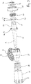
- the Fig. 1 shows an overview of a compressed air-operated disc brake with an integrated device for readjusting the wear-related clearance of the brake.
- a device for readjusting the wear-related clearance of the brake.
- Such a device is used, for example, in a sliding caliper disc brake intended for commercial vehicles to compensate for the brake lining wear associated with driving operation, but also the wear on the brake disc.
- the adjusting device is, together with elements of the brake application, arranged in a brake housing 1 which, for. B. the caliper of the disc brake can be.
- Fig. 1 Brake disk 2 shown in detail, connected to the vehicle wheel, against which a brake lining 3 works on each of its two sides. This is composed in the usual way of a lining back plate and the actual friction lining.
- Brake pressure is applied directly to the inner brake lining 3 by a plunger 7 which is movable against this brake lining and which rests against the backing plate of this inner brake lining 3 when the brake is applied.
- the pressure ram 7 is in a threaded connection 9, which is suitable for transmitting the full braking forces, with a pressure piece 10, which is arranged in the brake caliper 1 in a longitudinally movable manner.
- a clamping lever 15 is supported against the pressure piece 10.
- the application lever 15 is mounted in the brake housing 1 on a pivot axis parallel to the braking surfaces of the brake disc 2, and it is provided with a lever arm 17.
- the force element of the vehicle brake works against the lever arm 17. In the case of a compressed air-actuated disc brake, this force element is a pneumatic cylinder.
- the force generated by the force member is converted into a pivoting of the application lever 15 via the lever arm 17, whereby the lever ratios result in a pressure on the pressure piece 10 that increases the force of the force member.
- the arrangement of the force member, the lever arrangement and the pressure piece forms the application device of the vehicle brake.
- the application lever 15 works as an eccentric to increase the pressure.
- a fork-shaped design of the application lever 15 is shown. In this design, the actuating force and thus the braking force is transmitted to the pressure piece 10 in equal parts and on both sides of the adjusting device arranged centrally on the axis A.
- the adjustment device is used to compensate for the increasing clearance due to wear on the linings and the brake disc.
- this is at least partially integrated into the pressure ram 7 arranged centrally in the brake housing 1.
- the pressure plunger 7 is provided with a cavity 21 open facing away from the brake disc for at least parts of the adjustment device.
- the plunger 7 is closed.
- a component of the adjustment device is a drive element 25 which is rotatably arranged within the housing of the disc brake on an axis A parallel to the axis of rotation of the brake disc.
- the drive element 25 can be rotated about the axis A during the brake actuation by the application device of the brake and in particular by the action of the application lever 15.
- Components of the adjustment device are also an adjustment element 26 arranged on the same axis A, as well as a transmission device in the movement path between drive element 25 and adjustment element 26.
- adjustment element 26 is successively in the same direction through drive element 25 Rotational movements around axis A can be adjusted.
- a wrap spring 28, which is also arranged on axis A, is used here as the transmission device.
- the adjusting element 26 is non-rotatable with respect to the surrounding plunger 7, but is axially movable.
- the plunger 7 is provided on its inside with longitudinal grooves 34 in which projections or lugs 35 formed on the outside of the adjusting element 26 are guided in a longitudinally movable manner.
- a non-rotatable longitudinal guidance of the adjusting element 26 relative to the pressure plunger 7 is achieved.
- the relatively short lugs 35 in the longitudinal direction can compensate for a slight pivoting movement which cannot be avoided when the brake is applied.
- the drive element 25 is arranged essentially stationary in the longitudinal direction of the axis A in relation to the brake housing 1.
- the drive element 25 is provided with an outwardly protruding arm 37.
- the arm 37 forms a backdrop 36 ( Fig. 3 ), in which a pin 38 arranged on the application lever 15 engages.
- the link 36 on the arm 37 and the pin 38 together form a transmission, via which the drive element 25 can be driven by the movement of the application lever 15.
- the pivoting of the application lever 15 causes the drive element 25 to rotate about the axis A.
- both the drive element 25 and the adjustment element 26 are located on a shaft 40 arranged centrally on the axis A.
- the shaft 40 is axially essentially immovable with respect to the housing 1, but rotatable with respect to the Housing 1.
- the adjusting element 26 is connected to the shaft 40 in a fixed and in particular rotationally fixed manner.
- the drive element 25 is rotatably mounted on the shaft 40 and is also rotatable with respect to the adjustment element 26.
- the shaft 40 At its end facing away from the brake disk 2, the shaft 40 is provided with a polygon 39 as a key surface. A tool can be applied to this in order to return the adjusting device completely to its starting position by turning back the shaft 40, which is usually done when replacing used brake linings with new ones. At the latest after the old brake pads have been replaced with new ones 3, the adjustment must be manually returned to its starting position.
- the shaft 40 and thus at the same time the adjusting element 26 and the pressure ram are rotated in a direction of rotation which is opposite to the direction of rotation that occurs successively during the adjustment.
- the wrap spring 28, which serves to transmit the rotation between the drive element 25 and the adjustment element 26, can combine the functions of a one-way clutch with the function of an overload clutch. Details of the wrap spring 28 and its function are in the patent application WO 2015/117601 A1 described.
- the shaft 40 is supported twice with respect to the brake housing 1, in each case indirectly.
- the first support takes place via the adjustment element 26, which in turn is guided in the pressure ram 7, which in turn is supported in the pressure piece 10 via the threaded connection 9.
- the second support takes place on the other end, ie the end facing away from the brake disc.
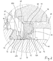
- the shaft 40 is according to Fig. 2 indirectly, namely via a cardanic pivot bearing 45, supported in a round opening 1A of the brake housing 1.
- the cardanic pivot bearing 45 is designed as a bearing bushing in such a way that it does not force the shaft 40 to be precisely axially aligned, but instead enables the shaft 40 to oscillate slightly relative to the housing 1.
- Fig. 2 this is achieved in that part of the cardanic pivot bearing 45 is an elastically deformable rubber or elastomer ring 46 to which a steel ring 47 is attached on the inside, for. B. by vulcanization.
- the steel ring 47 has an overall cylindrical inner contour, which forms a cylindrical sliding bearing surface 47A with which the steel ring 47 is slidably supported against a cylindrical bearing section 50 of the shaft 40.
- An outer steel ring 48 which is preferably also connected to the rubber or elastomer ring 46 by vulcanization, is part of the cardanic pivot bearing 45 designed as a bearing bushing. With the outer steel ring 48, the cardanic pivot bearing 45 sits in the surrounding opening 1A of the housing 1. The two steel rings 47, 48 have no direct contact, since the elastically flexible material of the rubber or elastomer ring 46 is located between them.
- the outer steel ring 48 is supported with part of its axial length against the cylindrical housing opening 1A and held firmly therein by frictional engagement.
- the steel ring 48 has an end region 49 facing the brake disk, which is provided with axially extending slots 49A to reduce the strength and is slightly deformed outward.
- the end region 49 enables the cardanic rotary bearing 45 to be fixed in the longitudinal direction in the manner of a latching behind an undercut formed next to the housing opening 1A in the housing 1.
- the inner steel ring 47 is provided with a step in such a way that the inner steel ring 47 has a longitudinal section 41 with a smaller inner diameter ( Fig. 4 ), on which the sliding bearing surface 47A is located for bearing against the cylindrical bearing section 50 of the shaft, and has a second longitudinal section 42 of larger inner diameter.
- a sealing lip 42A is attached by vulcanization, which lip seals against the cylindrical bearing section 50 of the shaft 40. In this way, no moisture and no dust can get into the area of the rotary bearing.
- a shaft seal can be used.
- the steel ring 47 is axially elongated in the form of a cylinder and is provided here with slots 43 extending axially, ie parallel to the axis A.
- the steel ring 47 points on the longitudinal section 41 ( Fig. 4 ) individual arms, separated from one another by the slots 43, which extend axially.
- the inner sides of these arms together form part of that cylindrical sliding bearing surface 47A, with which the steel ring 47 can slide on the cylindrical bearing section 50 of the shaft 40.
- the axially extending arms separated from one another by the slots 43 have a cylindrical inner contour on their inner sides, when viewed together, so that here there is a flat support on the cylindrical bearing section 50.
- This design of the inner steel ring 47 leads to relatively large contact surfaces between the sliding bearing surface 47A formed on the steel ring 47 and the cylindrical bearing section 50 of the shaft, whereby good sliding behavior is achieved with little susceptibility to wear.
- the slots 43 together with the arms formed in this way form form-locking elements by means of which a rotationally fixed connection of the steel ring 47 to a separate coupling ring 52 is achieved.
- the coupling ring 52 is provided at its ring opening 55 with corresponding form-locking elements, namely with alternately inwardly protruding first circumferential sections 56 towards the axis A and second circumferential sections that are set back 57, so they take turns.
- a pure rotary coupling is thereby achieved, which thus allows a free longitudinal movement of the coupling ring 52 with respect to the inner steel ring 47.
- the coupling ring 52 surrounds the shaft 40 and partly also the steel ring 47, and forms one component of a rotary coupling, which is composed as a whole of a first coupling part 51 and the coupling ring 52 as a second coupling part.
- the first coupling part 51 here is a collar 44 which is radially widened in comparison to the bearing section 50 and is integrally formed on the shaft 40.
- a spring element 60 which is designed as a wave spring, is supported on the one hand against the cardanic pivot bearing 45 and here preferably against its inner steel ring 47, and on the other hand against the coupling ring 52.
- the coupling ring 52 is provided with a circumferential step 61 which the wave spring 60 partially receives and centered with respect to the axis A.
- the spring is supported against an end face 62 on the step 61.
- the spring 60 ensures that the coupling ring, as the second coupling part 52, is permanently biased against the first coupling part 51 formed on the shaft 40.
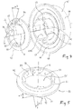
- Both coupling parts 51, 52 are provided with toothed coupling structures in the form of teeth or ramps distributed evenly over the circumference of the coupling parts.
- the tooth-shaped coupling structures are composed of first flanks 71, which form the ramps, and second flanks 72, wherein the first flanks 71 and the second flanks 72 alternate with one another, have an opposite inclination, and above all a different inclination or inclination.
- flank angles This is because the flank angle w1 of the first flanks 71 forming the ramps is approximately 30 ° and a maximum of 45 °.
- the flank angle w2 of the opposite flanks 72 is between 60 ° and 80 ° and preferably 70 °
- the flatter flanks 71 are important in the readjustment, in that the teeth move successively according to the wear of the disc brake, the ramps rising up one another and, in the case of overcoming the ramps, shifting by one tooth, with which the readjustment is carried out.
- the steeper flanks 72 have no direct significance in the readjustment, but in this respect they only serve as detents, that is to say block against unwanted turning back.
- the second flanks 72 are inclined at least to such an extent that they can be overcome when the force is consciously increased. This is the case when resetting the adjusting device by rotating the shaft 40 by means of a tool attached to its polygon 39. Sufficient torque can be built up via the tool in order to turn back the rotary coupling consisting of the coupling parts 51, 52 against the readjustment direction. This succeeds when the second flank angle w2 is between 60 ° and 80 °.
- the ring surfaces with the coupling structures are not arranged at right angles to the axis A, but are inclined.
- the annular surface 74 of the coupling ring 52, on which the teeth or ramps are formed is arranged conically in accordance with the entered angle w3.
- the other coupling part 51, d. H. the toothing formed directly on the collar 44 of the shaft has the angle w3.
- the cone angle measured between the annular surface 74 and the axis A is preferably between 55 ° and 65 °.
- the number of teeth or ramps on the second coupling part 52 is an integral multiple of the number of teeth or ramps on the first coupling part 51. This is a prerequisite for producing the shaft 40 inexpensively in an extrusion process in which very fine structures cannot easily be produced.
- the inner steel ring 47 is supported against an annular disk 75, which in turn is secured by a locking ring 76 which sits in a groove on the outer circumference of the shaft 40.
- a cap 80 made of a soft plastic can be placed on the housing opening 1A from the outside in order to additionally close it. This cap 80 helps to prevent moisture and dust from penetrating into the area of the pivot bearing and also into the area of the adjustment.
Landscapes
- Engineering & Computer Science (AREA)
- General Engineering & Computer Science (AREA)
- Mechanical Engineering (AREA)
- Braking Arrangements (AREA)
Priority Applications (4)
| Application Number | Priority Date | Filing Date | Title |
|---|---|---|---|
| DK20199255.9T DK3779229T3 (da) | 2016-03-24 | 2017-03-02 | Koblingsring |
| PL20199255T PL3779229T3 (pl) | 2016-03-24 | 2017-03-02 | Pierścień sprzęgłowy |
| PL17717618T PL3433508T3 (pl) | 2016-03-24 | 2017-03-02 | Mechanizm dosuwu dla hamulca tarczowego w pojeździe zaopatrzony w łożysko przegubowe Cardana i pierścień sprzęgający |
| EP20199255.9A EP3779229B1 (de) | 2016-03-24 | 2017-03-02 | Kupplungsring |
Applications Claiming Priority (2)
| Application Number | Priority Date | Filing Date | Title |
|---|---|---|---|
| DE102016105611.1A DE102016105611B4 (de) | 2016-03-24 | 2016-03-24 | Zustelleinrichtung für eine Fahrzeug-Scheibenbremse sowie kardanisches Drehlager und Kupplungsring hierfür |
| PCT/DE2017/100163 WO2017162229A2 (de) | 2016-03-24 | 2017-03-02 | Zustelleinrichtung für eine fahrzeug-scheibenbremse sowie kardanisches drehlager und kupplungsring hierfür |
Related Child Applications (2)
| Application Number | Title | Priority Date | Filing Date |
|---|---|---|---|
| EP20199255.9A Division EP3779229B1 (de) | 2016-03-24 | 2017-03-02 | Kupplungsring |
| EP20199255.9A Division-Into EP3779229B1 (de) | 2016-03-24 | 2017-03-02 | Kupplungsring |
Publications (2)
| Publication Number | Publication Date |
|---|---|
| EP3433508A2 EP3433508A2 (de) | 2019-01-30 |
| EP3433508B1 true EP3433508B1 (de) | 2020-12-16 |
Family
ID=58548499
Family Applications (2)
| Application Number | Title | Priority Date | Filing Date |
|---|---|---|---|
| EP17717618.7A Active EP3433508B1 (de) | 2016-03-24 | 2017-03-02 | Zustelleinrichtung für eine fahrzeugscheibenbremse mit kardanischem drehlager und kupplungsring |
| EP20199255.9A Active EP3779229B1 (de) | 2016-03-24 | 2017-03-02 | Kupplungsring |
Family Applications After (1)
| Application Number | Title | Priority Date | Filing Date |
|---|---|---|---|
| EP20199255.9A Active EP3779229B1 (de) | 2016-03-24 | 2017-03-02 | Kupplungsring |
Country Status (12)
| Country | Link |
|---|---|
| US (1) | US10982728B2 (pl) |
| EP (2) | EP3433508B1 (pl) |
| CN (1) | CN109073011B (pl) |
| AU (1) | AU2017239366B2 (pl) |
| DE (1) | DE102016105611B4 (pl) |
| DK (2) | DK3779229T3 (pl) |
| ES (2) | ES2847869T3 (pl) |
| HU (1) | HUE053182T2 (pl) |
| PL (2) | PL3433508T3 (pl) |
| RU (1) | RU2714092C1 (pl) |
| WO (1) | WO2017162229A2 (pl) |
| ZA (1) | ZA201805978B (pl) |
Families Citing this family (3)
| Publication number | Priority date | Publication date | Assignee | Title |
|---|---|---|---|---|
| DE102019116427A1 (de) * | 2019-06-18 | 2020-12-24 | Schaeffler Technologies AG & Co. KG | Bremsvorrichtung für ein Fahrzeug, Fahrzeug mit der Bremsvorrichtung und Verfahren zum Abbremsen eines rotierenden Rads eines Fahrzeugs mit der Bremsvorrichtung |
| IT202100027077A1 (it) * | 2021-10-21 | 2023-04-21 | Brembo Spa | Pinza per freno a disco |
| DE102024125604A1 (de) | 2024-09-06 | 2026-03-12 | Bpw Bergische Achsen Kommanditgesellschaft | Lagerkupplungsring, Nach- und Rücksteller, Scheibenbremse, Kupplungssystem |
Family Cites Families (40)
| Publication number | Priority date | Publication date | Assignee | Title |
|---|---|---|---|---|
| BE369400A (pl) * | ||||
| FR560109A (fr) * | 1922-12-21 | 1923-09-28 | Fermeture sans lacet pour ballons pour tous sports | |
| DE1600225B2 (de) * | 1967-04-20 | 1972-04-06 | Loesbare schnellkupplung zur verbindung zweier wellen, insbesondere fuer gelenkwellen | |
| DE1575659B1 (de) * | 1967-06-06 | 1971-07-01 | Stoeckicht Alexander W | Stirnzahnrad mit doppelschraegverzahnung |
| US3593390A (en) * | 1968-06-03 | 1971-07-20 | Ca Atomic Energy Ltd | Self-locking wedge ring support |
| DE7318918U (de) * | 1973-05-19 | 1973-08-16 | Skf Kugellagerfabriken Gmbh | Federbeinlagerung fur Kraftfahrzeuge |
| US4612816A (en) * | 1983-10-28 | 1986-09-23 | Lazar Chalik | Gear assembly |
| US4628753A (en) * | 1984-11-29 | 1986-12-16 | Dana Corporation | Lightweight ring gear for a differential |
| DE4034165A1 (de) * | 1990-06-07 | 1991-12-12 | Knorr Bremse Ag | Scheibenbremse fuer fahrzeuge |
| DE4020485A1 (de) | 1990-06-27 | 1992-01-02 | Knorr Bremse Ag | Scheibenbremse fuer fahrzeuge |
| DE4212406A1 (de) * | 1992-04-13 | 1993-10-14 | Knorr Bremse Ag | Druckluftbetätigte Scheibenbremse |
| US5380016A (en) * | 1992-11-12 | 1995-01-10 | Caterpillar Inc. | Radial lip seal |
| US5320587A (en) * | 1993-02-17 | 1994-06-14 | General Motors Corporation | Differential case with ring gear attachment |
| DE4334914A1 (de) * | 1993-10-13 | 1995-04-20 | Knorr Bremse Systeme | Druckluftbetätigte Scheibenbremse |
| EP0846883A1 (de) * | 1996-11-16 | 1998-06-10 | GETRAG Getriebe- und Zahnradfabrik Hermann Hagenmeyer GmbH & Cie | Synchronisationseinrichtung für Getriebe und Verfahren zum Anspitzen von Zähnen eines gesinterten Synchronisationskörpers |
| DE19814807C2 (de) * | 1998-04-02 | 2001-09-13 | Schaeffler Waelzlager Ohg | Nachstelleinrichtung für Scheibenbremsen |
| US6417211B1 (en) * | 1999-08-30 | 2002-07-09 | Rohm And Haas Company | Isothiazolone concentrates |
| DE10262110B4 (de) | 2002-12-23 | 2016-07-14 | Haldex Brake Products Ab | Bremsmechanismus für eine Scheibenbremse |
| US7854995B1 (en) * | 2004-07-14 | 2010-12-21 | Keystone Investment Corporation | High density dual helical gear |
| DE102004037771A1 (de) * | 2004-08-04 | 2006-03-16 | Knorr-Bremse Systeme für Nutzfahrzeuge GmbH | Nachstellvorrichtung für eine pneumatisch betätigte Scheibenbremse |
| DE102005018157B4 (de) * | 2005-04-20 | 2019-04-18 | Bpw Bergische Achsen Kg | Radbremse |
| DE102006031738A1 (de) * | 2006-07-10 | 2008-01-17 | Kastriot Merlaku | Brems-System für Fahrzeuge oder Maschinen aller Art |
| WO2008072742A1 (ja) * | 2006-12-14 | 2008-06-19 | Akebono Brake Industry Co., Ltd. | ディスクブレーキ装置 |
| US8342307B2 (en) * | 2006-12-22 | 2013-01-01 | Sulzer Euroflamm Germany Gmbh | Synchronizing ring |
| DE102007007493B4 (de) * | 2007-02-15 | 2018-12-13 | Bpw Bergische Achsen Kg | Zustelleinrichtung für eine Fahrzeug-Scheibenbremse |
| DE102007020022A1 (de) | 2007-04-28 | 2008-10-30 | Audi Ag | Aufbauseitige Federbeinlagerung für Radaufhängungen |
| FR2932237B1 (fr) * | 2008-06-04 | 2010-10-22 | France Reducteurs | Cone de friction et embrayage comportant un tel cone |
| DE102008035366A1 (de) * | 2008-07-30 | 2010-02-04 | Knorr-Bremse Systeme für Nutzfahrzeuge GmbH | Nachstellvorrichtung für eine Scheibenbremse |
| US8734022B2 (en) * | 2010-04-21 | 2014-05-27 | Aktiebolaget Skf | Sealing device for a hub and a bearing assembly including the sealing device |
| CN102155528A (zh) * | 2011-03-08 | 2011-08-17 | 江苏技术师范学院 | 塑料制圆锥齿轮 |
| DE102011117587A1 (de) * | 2011-11-03 | 2013-05-08 | Knorr-Bremse Systeme für Nutzfahrzeuge GmbH | Nachstellvorrichtung für eine Scheibenbremse |
| CN102401109A (zh) * | 2011-11-25 | 2012-04-04 | 扬州保来得科技实业有限公司 | 一种特殊粉末冶金齿轮盘及其制备方法 |
| ITTO20120307A1 (it) * | 2012-04-06 | 2013-10-07 | Skf Ab | Dispositivo anulare di tenuta |
| DE102012009900A1 (de) | 2012-05-18 | 2013-11-21 | Knorr-Bremse Systeme für Nutzfahrzeuge GmbH | Verschleißnachstellvorrichtung einer Scheibenbremse und entsprechende Scheibenbremse |
| DE102012108672B3 (de) | 2012-09-17 | 2014-02-06 | Knorr-Bremse Systeme für Nutzfahrzeuge GmbH | Nachstelleinrichtung einer Scheibenbremse, eine entsprechende Scheibenbremse und Verfahren zum Betreiben einer Verschleißnachstellvorrichtung einer Scheibenbremse |
| CN103216553B (zh) * | 2013-04-18 | 2016-08-03 | 芜湖伯特利汽车安全系统股份有限公司 | 一种应用于气压盘式制动器的间隙自动调整机构 |
| DE102014101341A1 (de) | 2014-02-04 | 2015-08-06 | Bpw Bergische Achsen Kg | Fahrzeugbremse, insbesondere Fahrzeug-Scheibenbremse |
| DE102014107477B4 (de) * | 2014-05-27 | 2018-09-06 | Vibracoustic Gmbh | Kardanwellenlager |
| CN105276040A (zh) * | 2014-05-29 | 2016-01-27 | 枣庄泰德机械有限公司 | 一种链条传动式高档客车制动间隙从动调整机构及制造方法 |
| US10240677B2 (en) * | 2015-04-07 | 2019-03-26 | Freudenberg Sealing Technologies S.A.S. Di Externa Italia S.R.L.U | Gasket |
-
2016
- 2016-03-24 DE DE102016105611.1A patent/DE102016105611B4/de active Active
-
2017
- 2017-03-02 ES ES17717618T patent/ES2847869T3/es active Active
- 2017-03-02 RU RU2018137185A patent/RU2714092C1/ru active
- 2017-03-02 US US16/087,679 patent/US10982728B2/en active Active
- 2017-03-02 PL PL17717618T patent/PL3433508T3/pl unknown
- 2017-03-02 CN CN201780025578.4A patent/CN109073011B/zh active Active
- 2017-03-02 PL PL20199255T patent/PL3779229T3/pl unknown
- 2017-03-02 EP EP17717618.7A patent/EP3433508B1/de active Active
- 2017-03-02 EP EP20199255.9A patent/EP3779229B1/de active Active
- 2017-03-02 DK DK20199255.9T patent/DK3779229T3/da active
- 2017-03-02 DK DK17717618.7T patent/DK3433508T3/da active
- 2017-03-02 HU HUE17717618A patent/HUE053182T2/hu unknown
- 2017-03-02 WO PCT/DE2017/100163 patent/WO2017162229A2/de not_active Ceased
- 2017-03-02 ES ES20199255T patent/ES2904724T3/es active Active
- 2017-03-02 AU AU2017239366A patent/AU2017239366B2/en active Active
-
2018
- 2018-09-06 ZA ZA2018/05978A patent/ZA201805978B/en unknown
Non-Patent Citations (1)
| Title |
|---|
| None * |
Also Published As
| Publication number | Publication date |
|---|---|
| RU2714092C1 (ru) | 2020-02-11 |
| US10982728B2 (en) | 2021-04-20 |
| HUE053182T2 (hu) | 2021-06-28 |
| EP3779229A1 (de) | 2021-02-17 |
| DK3779229T3 (da) | 2022-01-03 |
| WO2017162229A3 (de) | 2017-11-16 |
| DE102016105611A1 (de) | 2017-09-28 |
| ES2904724T3 (es) | 2022-04-05 |
| PL3433508T3 (pl) | 2021-07-26 |
| ZA201805978B (en) | 2019-06-26 |
| EP3779229B1 (de) | 2021-10-06 |
| AU2017239366A1 (en) | 2018-10-11 |
| PL3779229T3 (pl) | 2022-02-14 |
| AU2017239366B2 (en) | 2022-04-21 |
| WO2017162229A2 (de) | 2017-09-28 |
| DK3433508T3 (da) | 2021-03-15 |
| CN109073011B (zh) | 2020-08-21 |
| CN109073011A (zh) | 2018-12-21 |
| EP3433508A2 (de) | 2019-01-30 |
| US20200291995A1 (en) | 2020-09-17 |
| ES2847869T3 (es) | 2021-08-04 |
| DE102016105611B4 (de) | 2023-08-17 |
Similar Documents
| Publication | Publication Date | Title |
|---|---|---|
| EP0739459B1 (de) | Zuspannvorrichtung einer scheibenbremse, insbesondere für schwere nutzfahrzeuge | |
| EP2307755B1 (de) | Nachstellvorrichtung für eine scheibenbremse | |
| EP3695132B1 (de) | Spreizeinheit für trommelbremse mit verschleisswegnachstellung und die trommelbremse | |
| EP2318730B1 (de) | Nachstellvorrichtung für eine scheibenbremse | |
| WO2010012483A1 (de) | Nachstellvorrichtung für eine scheibenbremse | |
| DE202011106746U1 (de) | Bremshebel für eine Trommelbremse | |
| DE102015010348A1 (de) | Vorrichtung zur Befestigung eines Verschleißsensors an einem Bremshebel einer Fahrzeugbremse | |
| AT391005B (de) | Mechanische loeseeinrichtung fuer einen federspeicherbremszylinder | |
| EP3779229B1 (de) | Kupplungsring | |
| WO2013064482A1 (de) | Nachstellvorrichtung für eine scheibenbremse | |
| DE10214670B4 (de) | Bremszuspanneinrichtung mit elektrisch betätigtem Verschleißnachsteller | |
| EP3477157B1 (de) | Differentialsperre | |
| EP2831461B1 (de) | Bremsdrehhebel einer scheibenbremse und entsprechende scheibenbremse | |
| DE102011051073B4 (de) | Vorrichtung zum Nachstellen des verschleißbedingten Lüftspiels bei einer Fahrzeugbremse | |
| DE102013103064B4 (de) | Nachstelleinrichtung für eine Scheibenbremse und eine entsprechende Scheibenbremse | |
| DE102014113055A1 (de) | Nachstellvorrichtung für eine drehhebelbetätigte Scheibenbremse, und Scheibenbremse mit einer solchen Nachstellvorrichtung | |
| EP0181004A1 (de) | Nachstellbare Betätigungsvorrichtung für Bremsen, insbesondere Fahrzeug-Trommelbremsen | |
| DE102005041342B4 (de) | Gestängesteller für Trommelbremse | |
| EP4707081A1 (de) | Lagerkupplungsring, nach- und rücksteller, scheibenbremse, kupplungssystem | |
| DE10346343B4 (de) | An einer Radnabe befestigbare Bremsscheibe | |
| EP2292945A1 (de) | Scheibenbremse mit Rutschkupplung für die Nachstelleinrichtung | |
| DE102017208850B4 (de) | Linearaktuator und Bremssystem | |
| DE102007057933B4 (de) | Bolzenlagerung für einen an seinem Ende mit einem Kugelzapfen versehenen Bolzen | |
| DE1425369B1 (de) | Nachstellvorrichtung fuer die Bremsbacke einer Reibungsbremse,insbesondere einer Innenbackenbremse | |
| DD249162A3 (de) | Automatische nachstellvorrichtung, insbesondere fuer kraftfahrzeugbremsen |
Legal Events
| Date | Code | Title | Description |
|---|---|---|---|
| STAA | Information on the status of an ep patent application or granted ep patent |
Free format text: STATUS: UNKNOWN |
|
| STAA | Information on the status of an ep patent application or granted ep patent |
Free format text: STATUS: THE INTERNATIONAL PUBLICATION HAS BEEN MADE |
|
| PUAI | Public reference made under article 153(3) epc to a published international application that has entered the european phase |
Free format text: ORIGINAL CODE: 0009012 |
|
| STAA | Information on the status of an ep patent application or granted ep patent |
Free format text: STATUS: REQUEST FOR EXAMINATION WAS MADE |
|
| 17P | Request for examination filed |
Effective date: 20180906 |
|
| AK | Designated contracting states |
Kind code of ref document: A2 Designated state(s): AL AT BE BG CH CY CZ DE DK EE ES FI FR GB GR HR HU IE IS IT LI LT LU LV MC MK MT NL NO PL PT RO RS SE SI SK SM TR |
|
| AX | Request for extension of the european patent |
Extension state: BA ME |
|
| DAV | Request for validation of the european patent (deleted) | ||
| DAX | Request for extension of the european patent (deleted) | ||
| STAA | Information on the status of an ep patent application or granted ep patent |
Free format text: STATUS: EXAMINATION IS IN PROGRESS |
|
| 17Q | First examination report despatched |
Effective date: 20191217 |
|
| GRAP | Despatch of communication of intention to grant a patent |
Free format text: ORIGINAL CODE: EPIDOSNIGR1 |
|
| STAA | Information on the status of an ep patent application or granted ep patent |
Free format text: STATUS: GRANT OF PATENT IS INTENDED |
|
| INTG | Intention to grant announced |
Effective date: 20200730 |
|
| GRAS | Grant fee paid |
Free format text: ORIGINAL CODE: EPIDOSNIGR3 |
|
| GRAA | (expected) grant |
Free format text: ORIGINAL CODE: 0009210 |
|
| STAA | Information on the status of an ep patent application or granted ep patent |
Free format text: STATUS: THE PATENT HAS BEEN GRANTED |
|
| AK | Designated contracting states |
Kind code of ref document: B1 Designated state(s): AL AT BE BG CH CY CZ DE DK EE ES FI FR GB GR HR HU IE IS IT LI LT LU LV MC MK MT NL NO PL PT RO RS SE SI SK SM TR |
|
| REG | Reference to a national code |
Ref country code: GB Ref legal event code: FG4D Free format text: NOT ENGLISH |
|
| REG | Reference to a national code |
Ref country code: IE Ref legal event code: FG4D Free format text: LANGUAGE OF EP DOCUMENT: GERMAN |
|
| REG | Reference to a national code |
Ref country code: DE Ref legal event code: R096 Ref document number: 502017008693 Country of ref document: DE |
|
| REG | Reference to a national code |
Ref country code: NL Ref legal event code: FP |
|
| REG | Reference to a national code |
Ref country code: AT Ref legal event code: REF Ref document number: 1345877 Country of ref document: AT Kind code of ref document: T Effective date: 20210115 |
|
| REG | Reference to a national code |
Ref country code: SE Ref legal event code: TRGR |
|
| REG | Reference to a national code |
Ref country code: FI Ref legal event code: FGE |
|
| REG | Reference to a national code |
Ref country code: DK Ref legal event code: T3 Effective date: 20210311 |
|
| REG | Reference to a national code |
Ref country code: GR Ref legal event code: EP Ref document number: 20210400532 Country of ref document: GR Effective date: 20210416 |
|
| PG25 | Lapsed in a contracting state [announced via postgrant information from national office to epo] |
Ref country code: RS Free format text: LAPSE BECAUSE OF FAILURE TO SUBMIT A TRANSLATION OF THE DESCRIPTION OR TO PAY THE FEE WITHIN THE PRESCRIBED TIME-LIMIT Effective date: 20201216 Ref country code: NO Free format text: LAPSE BECAUSE OF FAILURE TO SUBMIT A TRANSLATION OF THE DESCRIPTION OR TO PAY THE FEE WITHIN THE PRESCRIBED TIME-LIMIT Effective date: 20210316 |
|
| PG25 | Lapsed in a contracting state [announced via postgrant information from national office to epo] |
Ref country code: BG Free format text: LAPSE BECAUSE OF FAILURE TO SUBMIT A TRANSLATION OF THE DESCRIPTION OR TO PAY THE FEE WITHIN THE PRESCRIBED TIME-LIMIT Effective date: 20210316 Ref country code: LV Free format text: LAPSE BECAUSE OF FAILURE TO SUBMIT A TRANSLATION OF THE DESCRIPTION OR TO PAY THE FEE WITHIN THE PRESCRIBED TIME-LIMIT Effective date: 20201216 |
|
| REG | Reference to a national code |
Ref country code: HU Ref legal event code: AG4A Ref document number: E053182 Country of ref document: HU |
|
| PG25 | Lapsed in a contracting state [announced via postgrant information from national office to epo] |
Ref country code: HR Free format text: LAPSE BECAUSE OF FAILURE TO SUBMIT A TRANSLATION OF THE DESCRIPTION OR TO PAY THE FEE WITHIN THE PRESCRIBED TIME-LIMIT Effective date: 20201216 |
|
| REG | Reference to a national code |
Ref country code: LT Ref legal event code: MG9D |
|
| PG25 | Lapsed in a contracting state [announced via postgrant information from national office to epo] |
Ref country code: SK Free format text: LAPSE BECAUSE OF FAILURE TO SUBMIT A TRANSLATION OF THE DESCRIPTION OR TO PAY THE FEE WITHIN THE PRESCRIBED TIME-LIMIT Effective date: 20201216 Ref country code: PT Free format text: LAPSE BECAUSE OF FAILURE TO SUBMIT A TRANSLATION OF THE DESCRIPTION OR TO PAY THE FEE WITHIN THE PRESCRIBED TIME-LIMIT Effective date: 20210416 Ref country code: RO Free format text: LAPSE BECAUSE OF FAILURE TO SUBMIT A TRANSLATION OF THE DESCRIPTION OR TO PAY THE FEE WITHIN THE PRESCRIBED TIME-LIMIT Effective date: 20201216 Ref country code: SM Free format text: LAPSE BECAUSE OF FAILURE TO SUBMIT A TRANSLATION OF THE DESCRIPTION OR TO PAY THE FEE WITHIN THE PRESCRIBED TIME-LIMIT Effective date: 20201216 Ref country code: EE Free format text: LAPSE BECAUSE OF FAILURE TO SUBMIT A TRANSLATION OF THE DESCRIPTION OR TO PAY THE FEE WITHIN THE PRESCRIBED TIME-LIMIT Effective date: 20201216 Ref country code: CZ Free format text: LAPSE BECAUSE OF FAILURE TO SUBMIT A TRANSLATION OF THE DESCRIPTION OR TO PAY THE FEE WITHIN THE PRESCRIBED TIME-LIMIT Effective date: 20201216 Ref country code: LT Free format text: LAPSE BECAUSE OF FAILURE TO SUBMIT A TRANSLATION OF THE DESCRIPTION OR TO PAY THE FEE WITHIN THE PRESCRIBED TIME-LIMIT Effective date: 20201216 |
|
| REG | Reference to a national code |
Ref country code: ES Ref legal event code: FG2A Ref document number: 2847869 Country of ref document: ES Kind code of ref document: T3 Effective date: 20210804 |
|
| REG | Reference to a national code |
Ref country code: DE Ref legal event code: R097 Ref document number: 502017008693 Country of ref document: DE |
|
| PG25 | Lapsed in a contracting state [announced via postgrant information from national office to epo] |
Ref country code: IS Free format text: LAPSE BECAUSE OF FAILURE TO SUBMIT A TRANSLATION OF THE DESCRIPTION OR TO PAY THE FEE WITHIN THE PRESCRIBED TIME-LIMIT Effective date: 20210416 |
|
| PLBE | No opposition filed within time limit |
Free format text: ORIGINAL CODE: 0009261 |
|
| STAA | Information on the status of an ep patent application or granted ep patent |
Free format text: STATUS: NO OPPOSITION FILED WITHIN TIME LIMIT |
|
| PG25 | Lapsed in a contracting state [announced via postgrant information from national office to epo] |
Ref country code: AL Free format text: LAPSE BECAUSE OF FAILURE TO SUBMIT A TRANSLATION OF THE DESCRIPTION OR TO PAY THE FEE WITHIN THE PRESCRIBED TIME-LIMIT Effective date: 20201216 Ref country code: MC Free format text: LAPSE BECAUSE OF FAILURE TO SUBMIT A TRANSLATION OF THE DESCRIPTION OR TO PAY THE FEE WITHIN THE PRESCRIBED TIME-LIMIT Effective date: 20201216 |
|
| REG | Reference to a national code |
Ref country code: CH Ref legal event code: PL |
|
| 26N | No opposition filed |
Effective date: 20210917 |
|
| PG25 | Lapsed in a contracting state [announced via postgrant information from national office to epo] |
Ref country code: LI Free format text: LAPSE BECAUSE OF NON-PAYMENT OF DUE FEES Effective date: 20210331 Ref country code: LU Free format text: LAPSE BECAUSE OF NON-PAYMENT OF DUE FEES Effective date: 20210302 Ref country code: CH Free format text: LAPSE BECAUSE OF NON-PAYMENT OF DUE FEES Effective date: 20210331 Ref country code: IE Free format text: LAPSE BECAUSE OF NON-PAYMENT OF DUE FEES Effective date: 20210302 |
|
| PG25 | Lapsed in a contracting state [announced via postgrant information from national office to epo] |
Ref country code: SI Free format text: LAPSE BECAUSE OF FAILURE TO SUBMIT A TRANSLATION OF THE DESCRIPTION OR TO PAY THE FEE WITHIN THE PRESCRIBED TIME-LIMIT Effective date: 20201216 |
|
| REG | Reference to a national code |
Ref country code: DE Ref legal event code: R082 Ref document number: 502017008693 Country of ref document: DE Representative=s name: DREISS PATENTANWAELTE PARTG MBB, DE |
|
| P01 | Opt-out of the competence of the unified patent court (upc) registered |
Effective date: 20230508 |
|
| PG25 | Lapsed in a contracting state [announced via postgrant information from national office to epo] |
Ref country code: CY Free format text: LAPSE BECAUSE OF FAILURE TO SUBMIT A TRANSLATION OF THE DESCRIPTION OR TO PAY THE FEE WITHIN THE PRESCRIBED TIME-LIMIT Effective date: 20201216 |
|
| PG25 | Lapsed in a contracting state [announced via postgrant information from national office to epo] |
Ref country code: MK Free format text: LAPSE BECAUSE OF FAILURE TO SUBMIT A TRANSLATION OF THE DESCRIPTION OR TO PAY THE FEE WITHIN THE PRESCRIBED TIME-LIMIT Effective date: 20201216 |
|
| PG25 | Lapsed in a contracting state [announced via postgrant information from national office to epo] |
Ref country code: MT Free format text: LAPSE BECAUSE OF FAILURE TO SUBMIT A TRANSLATION OF THE DESCRIPTION OR TO PAY THE FEE WITHIN THE PRESCRIBED TIME-LIMIT Effective date: 20201216 |
|
| PGFP | Annual fee paid to national office [announced via postgrant information from national office to epo] |
Ref country code: DE Payment date: 20250512 Year of fee payment: 9 |
|
| PGFP | Annual fee paid to national office [announced via postgrant information from national office to epo] |
Ref country code: ES Payment date: 20250416 Year of fee payment: 9 |
|
| PGFP | Annual fee paid to national office [announced via postgrant information from national office to epo] |
Ref country code: IT Payment date: 20250331 Year of fee payment: 9 |
|
| PGFP | Annual fee paid to national office [announced via postgrant information from national office to epo] |
Ref country code: SE Payment date: 20260323 Year of fee payment: 10 |
|
| PGFP | Annual fee paid to national office [announced via postgrant information from national office to epo] |
Ref country code: GB Payment date: 20260216 Year of fee payment: 10 |
|
| PGFP | Annual fee paid to national office [announced via postgrant information from national office to epo] |
Ref country code: DK Payment date: 20260323 Year of fee payment: 10 |
|
| PGFP | Annual fee paid to national office [announced via postgrant information from national office to epo] |
Ref country code: AT Payment date: 20260319 Year of fee payment: 10 |
|
| PGFP | Annual fee paid to national office [announced via postgrant information from national office to epo] |
Ref country code: FI Payment date: 20260320 Year of fee payment: 10 Ref country code: BE Payment date: 20260323 Year of fee payment: 10 |
|
| PGFP | Annual fee paid to national office [announced via postgrant information from national office to epo] |
Ref country code: HU Payment date: 20260225 Year of fee payment: 10 Ref country code: NL Payment date: 20260323 Year of fee payment: 10 |
|
| PGFP | Annual fee paid to national office [announced via postgrant information from national office to epo] |
Ref country code: FR Payment date: 20260324 Year of fee payment: 10 |
|
| PGFP | Annual fee paid to national office [announced via postgrant information from national office to epo] |
Ref country code: TR Payment date: 20260224 Year of fee payment: 10 |
|
| PGFP | Annual fee paid to national office [announced via postgrant information from national office to epo] |
Ref country code: GR Payment date: 20260319 Year of fee payment: 10 Ref country code: PL Payment date: 20260115 Year of fee payment: 10 |