EP3433090B1 - Maximisation de la durée de moyens de guidage dans des systèmes de vulcanisation de pneumatiques sans perturber la stabilité thermique - Google Patents
Maximisation de la durée de moyens de guidage dans des systèmes de vulcanisation de pneumatiques sans perturber la stabilité thermique Download PDFInfo
- Publication number
- EP3433090B1 EP3433090B1 EP17707545.4A EP17707545A EP3433090B1 EP 3433090 B1 EP3433090 B1 EP 3433090B1 EP 17707545 A EP17707545 A EP 17707545A EP 3433090 B1 EP3433090 B1 EP 3433090B1
- Authority
- EP
- European Patent Office
- Prior art keywords
- heating medium
- bearings
- tire vulcanization
- vulcanization system
- tire
- Prior art date
- Legal status (The legal status is an assumption and is not a legal conclusion. Google has not performed a legal analysis and makes no representation as to the accuracy of the status listed.)
- Active
Links
- 238000004073 vulcanization Methods 0.000 title claims description 39
- 238000010438 heat treatment Methods 0.000 claims description 63
- IJGRMHOSHXDMSA-UHFFFAOYSA-N Atomic nitrogen Chemical compound N#N IJGRMHOSHXDMSA-UHFFFAOYSA-N 0.000 claims description 9
- 239000000314 lubricant Substances 0.000 claims description 8
- 238000000034 method Methods 0.000 claims description 6
- 229910052757 nitrogen Inorganic materials 0.000 claims description 5
- 239000000463 material Substances 0.000 claims description 4
- 230000000153 supplemental effect Effects 0.000 claims description 3
- OKTJSMMVPCPJKN-UHFFFAOYSA-N Carbon Chemical compound [C] OKTJSMMVPCPJKN-UHFFFAOYSA-N 0.000 claims description 2
- BWGNESOTFCXPMA-UHFFFAOYSA-N Dihydrogen disulfide Chemical compound SS BWGNESOTFCXPMA-UHFFFAOYSA-N 0.000 claims description 2
- 229910002804 graphite Inorganic materials 0.000 claims description 2
- 239000010439 graphite Substances 0.000 claims description 2
- CWQXQMHSOZUFJS-UHFFFAOYSA-N molybdenum disulfide Chemical group S=[Mo]=S CWQXQMHSOZUFJS-UHFFFAOYSA-N 0.000 claims description 2
- 229910052982 molybdenum disulfide Inorganic materials 0.000 claims description 2
- 230000001105 regulatory effect Effects 0.000 claims description 2
- 238000000605 extraction Methods 0.000 description 9
- 150000001875 compounds Chemical class 0.000 description 4
- 230000000295 complement effect Effects 0.000 description 3
- 230000000694 effects Effects 0.000 description 3
- 239000010702 perfluoropolyether Substances 0.000 description 3
- 230000004907 flux Effects 0.000 description 2
- 238000012986 modification Methods 0.000 description 2
- 230000004048 modification Effects 0.000 description 2
- 239000003921 oil Substances 0.000 description 2
- 230000008569 process Effects 0.000 description 2
- 241000083700 Ambystoma tigrinum virus Species 0.000 description 1
- 239000004215 Carbon black (E152) Substances 0.000 description 1
- RYGMFSIKBFXOCR-UHFFFAOYSA-N Copper Chemical compound [Cu] RYGMFSIKBFXOCR-UHFFFAOYSA-N 0.000 description 1
- 239000004642 Polyimide Substances 0.000 description 1
- XAGFODPZIPBFFR-UHFFFAOYSA-N aluminium Chemical compound [Al] XAGFODPZIPBFFR-UHFFFAOYSA-N 0.000 description 1
- 229910052782 aluminium Inorganic materials 0.000 description 1
- 229920005549 butyl rubber Polymers 0.000 description 1
- 229910010293 ceramic material Inorganic materials 0.000 description 1
- 238000004891 communication Methods 0.000 description 1
- 239000004020 conductor Substances 0.000 description 1
- 229910052802 copper Inorganic materials 0.000 description 1
- 239000010949 copper Substances 0.000 description 1
- 239000013013 elastic material Substances 0.000 description 1
- 229920001971 elastomer Polymers 0.000 description 1
- 238000005516 engineering process Methods 0.000 description 1
- 238000000265 homogenisation Methods 0.000 description 1
- 229930195733 hydrocarbon Natural products 0.000 description 1
- 150000002430 hydrocarbons Chemical class 0.000 description 1
- 238000009434 installation Methods 0.000 description 1
- 238000005259 measurement Methods 0.000 description 1
- 230000007246 mechanism Effects 0.000 description 1
- 238000005065 mining Methods 0.000 description 1
- QJGQUHMNIGDVPM-UHFFFAOYSA-N nitrogen group Chemical group [N] QJGQUHMNIGDVPM-UHFFFAOYSA-N 0.000 description 1
- 239000004033 plastic Substances 0.000 description 1
- 229920003023 plastic Polymers 0.000 description 1
- 229920001721 polyimide Polymers 0.000 description 1
- 230000002035 prolonged effect Effects 0.000 description 1
- 238000007789 sealing Methods 0.000 description 1
- 230000008719 thickening Effects 0.000 description 1
- 238000012546 transfer Methods 0.000 description 1
- 238000009423 ventilation Methods 0.000 description 1
Images


Classifications
-
- B—PERFORMING OPERATIONS; TRANSPORTING
- B29—WORKING OF PLASTICS; WORKING OF SUBSTANCES IN A PLASTIC STATE IN GENERAL
- B29D—PRODUCING PARTICULAR ARTICLES FROM PLASTICS OR FROM SUBSTANCES IN A PLASTIC STATE
- B29D30/00—Producing pneumatic or solid tyres or parts thereof
- B29D30/06—Pneumatic tyres or parts thereof (e.g. produced by casting, moulding, compression moulding, injection moulding, centrifugal casting)
- B29D30/0601—Vulcanising tyres; Vulcanising presses for tyres
- B29D30/0662—Accessories, details or auxiliary operations
-
- B—PERFORMING OPERATIONS; TRANSPORTING
- B29—WORKING OF PLASTICS; WORKING OF SUBSTANCES IN A PLASTIC STATE IN GENERAL
- B29D—PRODUCING PARTICULAR ARTICLES FROM PLASTICS OR FROM SUBSTANCES IN A PLASTIC STATE
- B29D30/00—Producing pneumatic or solid tyres or parts thereof
- B29D30/06—Pneumatic tyres or parts thereof (e.g. produced by casting, moulding, compression moulding, injection moulding, centrifugal casting)
- B29D30/0601—Vulcanising tyres; Vulcanising presses for tyres
- B29D30/0654—Flexible cores therefor, e.g. bladders, bags, membranes, diaphragms
- B29D2030/0657—Removing the vulcanizing media from the flexible cores, e.g. draining or evacuating
-
- B—PERFORMING OPERATIONS; TRANSPORTING
- B29—WORKING OF PLASTICS; WORKING OF SUBSTANCES IN A PLASTIC STATE IN GENERAL
- B29D—PRODUCING PARTICULAR ARTICLES FROM PLASTICS OR FROM SUBSTANCES IN A PLASTIC STATE
- B29D30/00—Producing pneumatic or solid tyres or parts thereof
- B29D30/06—Pneumatic tyres or parts thereof (e.g. produced by casting, moulding, compression moulding, injection moulding, centrifugal casting)
- B29D30/0601—Vulcanising tyres; Vulcanising presses for tyres
- B29D30/0662—Accessories, details or auxiliary operations
- B29D2030/0666—Heating by using fluids
- B29D2030/0667—Circulating the fluids, e.g. introducing and removing them into and from the moulds; devices therefor
- B29D2030/0669—Circulating the fluids, e.g. introducing and removing them into and from the moulds; devices therefor the fluids being circulated by a turbine type pump associated with the mould, e.g. positioned in the mould
-
- B—PERFORMING OPERATIONS; TRANSPORTING
- B29—WORKING OF PLASTICS; WORKING OF SUBSTANCES IN A PLASTIC STATE IN GENERAL
- B29D—PRODUCING PARTICULAR ARTICLES FROM PLASTICS OR FROM SUBSTANCES IN A PLASTIC STATE
- B29D30/00—Producing pneumatic or solid tyres or parts thereof
- B29D30/06—Pneumatic tyres or parts thereof (e.g. produced by casting, moulding, compression moulding, injection moulding, centrifugal casting)
- B29D30/0601—Vulcanising tyres; Vulcanising presses for tyres
- B29D30/0662—Accessories, details or auxiliary operations
- B29D2030/0675—Controlling the vulcanization processes
- B29D2030/0677—Controlling temperature differences
-
- B—PERFORMING OPERATIONS; TRANSPORTING
- B29—WORKING OF PLASTICS; WORKING OF SUBSTANCES IN A PLASTIC STATE IN GENERAL
- B29D—PRODUCING PARTICULAR ARTICLES FROM PLASTICS OR FROM SUBSTANCES IN A PLASTIC STATE
- B29D30/00—Producing pneumatic or solid tyres or parts thereof
- B29D30/06—Pneumatic tyres or parts thereof (e.g. produced by casting, moulding, compression moulding, injection moulding, centrifugal casting)
- B29D30/0601—Vulcanising tyres; Vulcanising presses for tyres
- B29D30/0603—Loading or unloading the presses
-
- B—PERFORMING OPERATIONS; TRANSPORTING
- B29—WORKING OF PLASTICS; WORKING OF SUBSTANCES IN A PLASTIC STATE IN GENERAL
- B29L—INDEXING SCHEME ASSOCIATED WITH SUBCLASS B29C, RELATING TO PARTICULAR ARTICLES
- B29L2030/00—Pneumatic or solid tyres or parts thereof
Definitions
- the invention is generally directed to tire vulcanization and systems used therefor. More particularly, the invention is directed to maximizing the service life of guidance means that are used in such systems while preserving the thermal stability of the vulcanization.
- one or more tire vulcanizing systems may be employed for use with a tire mold.
- a principal characteristic of certain vulcanization systems is to place a system of heating and ventilation at the heart of an electric vulcanization system.
- a circulation fan that is immersed wholly in a heating medium (typically nitrogen) circulates the heating medium inside a bladder (i.e., one formed from an elastic material such as butyl rubber).
- a heating means that is also immersed wholly in the heating medium supplies the required heat, thereby causing the bladder to expand and engage an inner wall surface of the tire. Exemplary embodiments of such systems and demonstrations of their use are disclosed by the publications EP0686492 and US7435069 .
- lubricants that are commonly used in these installations are generally inert oils such as perfluoropolyether (PFPE) which offer excellent high temperature performance.
- PFPE perfluoropolyether
- the vulcanization of a tire at high temperatures introduces compounds that are mainly hydrocarbon-based oils. These compounds are not miscible with PFPE.
- the invention provides a tire vulcanization system for regulating a temperature of a heating medium such as nitrogen.
- the system includes a bladder that is disposed within a tire to be vulcanized.
- the bladder defines a cavity in which the heating medium circulates.
- a fan and a heater are immersed in the heating medium.
- the heater has one or more heating elements that supply energy to the heating medium before the heating medium exits the bladder along an output path.
- a shaft is also provided that is concentric with an axis X-X' of the cavity and driven by a controllable motor.
- Guidance protection means are positioned in a central portion of the system at or near a center of the bladder and below the fan and the heater.
- the fan agitates the heating medium radially outwardly in the direction of the bladder and directs the heating medium toward exits that are positioned obliquely relative to a support that carries the fan.
- the heating medium in the cavity may be pressurized at an operating temperature between about 130°C and about 220°C.
- the guidance protection means may include one or more bearings that are positioned in a central portion of the bladder.
- the bearing can include upper bearings that are disposed proximate the heater and the fan as well as lower bearings.
- the lower bearings are disposed opposite the upper bearings proximate an egress of the heating medium from one or more conduits.
- the upper and lower bearings can include at least one of integral protection means and supplemental exterior protection means.
- the guidance protection means may include one or more mechanical seals in combination with at least one of the upper bearings and the lower bearings.
- Each seal includes a stationary ring, a mobile grain and a spring washer that maintains contact therebetween.
- the guidance protection means may include the lower bearings and one or more plain bearings that replace the upper bearings and the mechanical seals.
- the plain bearings are fabricated from a material that undergoes pressure loads at an operating temperature between 130°C and 220°C.
- the guidance protection means may include the upper bearings and at least one joint.
- the joint includes a generally flexible member that remains in flexible contact with a housing body such that the joint establishes privileged passages that isolate the heating medium to an annular region.
- the invention also provides a tire vulcanization system that includes a mold within which a tire is vulcanized.
- the invention also provides a method for vulcanizing a tire in a mold for a predetermined duration under pressure.
- FIG. 1 shows an exemplary system 100 for producing one or more rubber products to be incorporated into one or more vehicle tires.
- tires includes but is not limited to tires used with lightweight vehicles, passenger vehicles, utility vehicles (including heavy trucks), leisure vehicles (including but not limited to bicycles, motorcycles, ATVs, etc.), agricultural vehicles, industrial vehicles, mining vehicles and engineering machines. It is also contemplated that the products produced by the presently disclosed invention include full and partial tire treads such as those used in known retreading processes.
- the heating medium may be selected from a plurality of suitable heating media.
- the heating medium is nitrogen which has a negligible interdependence between the pressure and temperature. This attribute is suitable for embodiments of the invention in which pressure loads are realized at an operating temperature between 130°C and 220°C.
- the invention is characterized in that guidance protection means are positioned in the lower part of a center mold below the fan and the heater. This configuration, which is realized in several embodiments, suppresses the temperature rises that are attributable to blockage of the guidance means. As pressure changes during a cure cycle, the system effects homogenization of the temperature through the entire volume of the enclosure.
- FIG. 1 shows a tire vulcanization system 100.
- System 100 includes an axially movable plate 116 and a fixed plate 118 that are connected by a flexible bladder 120.
- Counterplates 117, 119 anchor bladder 120 to respective plates 116, 118 along a circumference thereof.
- Bladder 120 and plates 116, 118 together delineate a fluid-tight enclosure 112 having a cavity 114 for containing a heating medium under pressure (e.g., nitrogen).
- Bladder 120 cooperates in a known manner with a rigid tire mold (not shown) intended to form an outer tire shape and sculpture.
- a heater 124 is enveloped within cavity 114 and thus fully immersed in the heating medium during operation of system 100.
- Heater 124 is shown as a coil member having heating elements 124a generally formed in an annular shape, although it is understood that heater 124 may be selected from any known heater mechanism that is amenable to practice with the invention.
- Heating elements 124a are operable with a fan 126 having a diametrical extent delineated by a plurality of blades 126a.
- One or more blades 126a may have a high thermal conductive material at least partially integrated therewith, including but not limited to copper, aluminum and comparable and equivalent materials.
- a power source (such as an electric power source, not shown) that is in communication with heater 124 and fan 126 ensures uninterrupted control and operation of both elements within cavity 114.
- a central portion of enclosure 112 includes an operating shaft 122 that is reciprocatable relative to a fixed mold along an axis X-X' of the enclosure.
- Operating shaft 122 effects exemplary axial movement of plate 116 between a vulcanization position in which bladder 120 abuts an inner wall surface P s ' of tire P' and an extraction position in which bladder 120 collapses.
- a rotor 130 effects circumferential rotation of a support 125 that carries fan 126. As is known in the art, rotor 130 sufficiently actuates fan blades 126a so as to impart a prescribed tangential velocity to the ejected heating medium.
- FIGS. 2A and 2B System 100 is further shown in FIGS. 2A and 2B .
- a curing cycle in which a tire (P') is vulcanized in a mold for a predetermined duration under pressure (herein “duration under pressure")
- one or more conduits 132 that are delineated in a stationary housing body 134 introduce the pressurized heating medium into cavity 114 (see FIG. 2A ).
- the heating medium is introduced into the cavity as needed (e.g., continuously or periodically) to maintain sufficient heat transfer along bladder 120 and wall 120a thereof.
- a valve (not shown) may be provided for automatic introduction and extraction of the heating medium.
- the heating medium is supplied from a heating medium supply (not shown) as is known in the art.
- a heating medium supply may optionally include a preheating device that previously heats the heating medium prior to introduction thereof in cavity 114.
- conduit 132 may include one or more conduits that are also employed for the extraction of the heating medium upon termination of a curing cycle (see Fig. 2B ).
- Guidance protection means are provided in the form of bearings 140, 140' that are positioned in a central portion of system 100 (e.g., at or near the center of bladder 120). Upper bearings 140 are disposed proximate heater 124 and fan 126 while lower bearings 140' are disposed opposite bearings 140 proximate an egress of the heating medium from conduits 132. As the heating medium is introduced through conduits 132, the rotation of fan 126 agitates the heating medium radially outwardly in the direction of the bladder 120 (i.e., along a path as shown by the arrows in FIG. 2A ). Conduits 132 direct the heating medium toward exits 133 that are positioned obliquely relative to support 125. This configuration ensures uniform and effective circumferential distribution of the heating medium throughout cavity 114.
- bearings 140, 140' avoid contact with harmful compounds that are created during the curing cycle. Bearings 140, 140' and their placement also preserve the effectiveness of the curing cycle by suppressing the temperature rise attributable to the increase in resistant strains in the bearings. Bearings 140, 140' can include integral or supplemental exterior protection. In some embodiments, bearings 140, 140' include bearings that are sealed on both sides (e.g., 2RS type). In some embodiments, the bearings can be treated with a dry lubricant such as molybdenum disulfide or graphite disulfide.
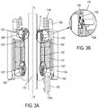
- FIGS. 3A and 3B illustrate another embodiment of system 100 in which the guidance protection means are in the form of mechanical seals 150 in combination with the upper bearings 140 and/or the lower bearings 140'.
- mechanical seals 150 complement both the upper bearings 140 and the lower bearings 140'.
- Each seal 150 includes a stationary ring 152, a mobile grain 154 and spring washer 156 which maintains contact therebetween.
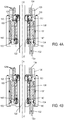
- Seal 150 prevents the passage of the heating medium during introduction into (i.e., along a path as shown by the arrows in FIG. 4A ) and extraction from (i.e., along a path as shown by the arrows in FIG. 4B ) cavity 114.
- the heating medium passes, rather, in an annular area between stator 131 and housing body 134.
- Seal 150 provides a sealing function that is decoupled from the rotation function, thereby resolving the problem of increased resistant forces in the bearings.
- FIG. 5 illustrates another embodiment of system 100 in which, in a position proximate support 125, plain bearings 160 replace upper bearings 140 and commensurate seals 150.
- Lower bearings 140' remain in a position distal to plain bearings 160.
- optional seals that are comparable to seals 150 may complement bearings 140'.
- plain bearings 160 are fabricated from a material that undergoes pressure loads at an operating temperature between 130°C and 220°C (e.g., one or more ceramic materials, high-performance plastics such as polyimide, etc.).
- the lubricants can be used in a manner known in the art.
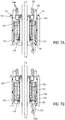
- FIGS. 6 , 7A and 7B provide another embodiment of system 100 wherein at least one joint 170 complements upper bearings 140 that are positioned proximate heater 124 and fan 126.
- Joints 170 may comprise generally flexible members that remain in flexible contact with housing body 134 and thereby complement protection of lower bearings 140'.
- joints 170 establish preferential passages 172 that isolate the heating medium to an annular region. The flow of the heating medium across the motor remains negligible, and upper bearings 140 remain essentially free of debris even with the use lubricants in a manner known in the art.
- the invention solves the problem of internal resistance that affects the performance of the guidance means used in vulcanization systems.
- a minimum film thickness can initially allow acceptable operating conditions.
- small perturbations in the operation of the bearings will lead to immobilization.
- the proper functioning of the bearings is realized without making fundamental changes in the existing procedures.
- heat flux can be increased in a controlled manner during a curing cycle to ensure sufficient heat flux for vulcanization.
- the energy which is necessary for vulcanization of a tire is the energy that carries the tire from its initial temperature (e.g., room temperature) to the desired temperature of vulcanization.
- Power is provided internally by the heating medium and on the outside by the mold.
- dimensions and values disclosed herein are not limited to a specified unit of measurement.
- dimensions expressed in English units are understood to include equivalent dimensions in metric and other units (e.g., a dimension disclosed as "1 inch” is intended to mean an equivalent dimension of "2.5 cm”).
- method or “process” may include one or more steps performed at least by one electronic or computer-based apparatus having a processor for executing instructions that carry out the steps.
Landscapes
- Engineering & Computer Science (AREA)
- Mechanical Engineering (AREA)
- Moulds For Moulding Plastics Or The Like (AREA)
- Heating, Cooling, Or Curing Plastics Or The Like In General (AREA)
Claims (13)
- Système de vulcanisation de pneu (100) destiné à réguler une température d'un fluide de chauffage, le système comprenant une vessie (120) disposée à l'intérieur d'un pneu (P ') à vulcaniser et définissant une cavité (114) dans laquelle circule le fluide de chauffage, avec un ventilateur (126) et un dispositif de chauffage (124) immergé dans le fluide de chauffage, le dispositif de chauffage ayant un ou plusieurs éléments de chauffage (124a) qui fournissent de l'énergie au fluide de chauffage avant de sortir le long d'un chemin de sortie, et avec un arbre (122) concentrique à un axe X-X ' de la cavité, et avec un moteur contrôlable (130, 131) entraînant l'arbre (122) ;
caractérisé en ce que des moyens de protection de guidage (140, 150, 160, 170) sont positionnés dans une portion centrale du système au niveau d'un centre de la vessie (120) ou à proximité de celui-ci, et en dessous du ventilateur (126) et du dispositif de chauffage (124), de telle sorte qu'à mesure que le fluide de chauffage est introduit dans la cavité (114), le ventilateur (126) agite le fluide de chauffage radialement vers l'extérieur dans la direction de la vessie (120) et dirige le fluide de chauffage vers des sorties (133) qui sont positionnées obliquement par rapport à un support (125) qui porte le ventilateur (126). - Système de vulcanisation de pneu selon la revendication 1, dans lequel le fluide de chauffage dans la cavité (114) est pressurisé à une température fonctionnelle comprise entre environ 130 °C et environ 220 °C.
- Système de vulcanisation de pneu selon la revendication 1 ou la revendication 2, dans lequel les moyens de protection de guidage comprennent un ou plusieurs paliers (140, 140') qui sont positionnés dans une portion centrale de la vessie et qui comportent des paliers supérieurs (140) disposés à proximité du dispositif de chauffage (124) et du ventilateur (126) et des paliers inférieurs (140') disposés en regard des paliers (140) à proximité d'une sortie du fluide de chauffage hors d'un ou de plusieurs conduits (132).
- Système de vulcanisation de pneu selon la revendication 3, dans lequel les paliers (140, 140') comportent un moyen de protection intégré et/ou un moyen de protection extérieur supplémentaire.
- Système de vulcanisation de pneu selon la revendication 3 ou la revendication 4, dans lequel les moyens de protection de guidage comprennent un ou plusieurs joints mécaniques (150) en combinaison avec au moins l'un de paliers supérieurs (140) et de paliers inférieurs (140'), et chaque joint comporte une bague stationnaire (152), un grain mobile (154) et une rondelle élastique (156) qui maintient le contact entre eux.
- Système de vulcanisation de pneu selon l'une quelconque des revendications 3 à 5, dans lequel les moyens de protection de guidage comprennent les paliers inférieurs (140) et un ou plusieurs paliers simples (160) qui remplacent les paliers supérieurs (140) et les joints (150).
- Système de vulcanisation de pneu selon la revendication 6, dans lequel les paliers simples (160) sont fabriqués à partir d'un matériau qui est soumis à des contraintes de pression à une température fonctionnelle entre 130 °C et 220 °C.
- Système de vulcanisation de pneu selon l'une quelconque des revendications 3 à 5, dans lequel les moyens de protection de guidage comprennent les paliers supérieurs (140) et au moins un joint (170) comprenant un organe généralement flexible qui reste en contact flexible avec le corps de boîtier (134) de telle sorte que le joint (170) établisse des passages privilégiés (172) qui isolent le fluide de chauffage par rapport à une région annulaire.
- Système de vulcanisation de pneu (100) selon l'une quelconque des revendications 1 à 8, dans lequel les moyens de protection de guidage (140, 150, 160) sont traités avec un lubrifiant sec.
- Système de vulcanisation de pneu (100) selon la revendication 9, dans lequel le lubrifiant sec est choisi parmi du disulfure de molybdène ou du disulfure de graphite.
- Système de vulcanisation de pneu (100) selon l'une quelconque des revendications 1 à 10, dans lequel le fluide de chauffage comprend de l'azote.
- Système de vulcanisation de pneu (100) selon l'une quelconque des revendications 1 à 11, comprenant en outre un moule à l'intérieur duquel est vulcanisé le pneu (P ').
- Procédé de vulcanisation d'un pneu (P') dans un moule pendant une durée prédéterminée sous pression, comprenant la fourniture du système de vulcanisation de pneu (100) selon l'une quelconque des revendications 1 à 12.
Applications Claiming Priority (2)
| Application Number | Priority Date | Filing Date | Title |
|---|---|---|---|
| FR1652394A FR3048913B1 (fr) | 2016-03-21 | 2016-03-21 | Maximiser la duree de vie de moyens de guidage dans les systemes de vulcanisation de pneus sans affecter la stabilite thermique |
| PCT/EP2017/054473 WO2017162407A1 (fr) | 2016-03-21 | 2017-02-27 | Maximisation de la durée de moyens de guidage dans des systèmes de vulcanisation de pneumatiques sans perturber la stabilité thermique |
Publications (2)
| Publication Number | Publication Date |
|---|---|
| EP3433090A1 EP3433090A1 (fr) | 2019-01-30 |
| EP3433090B1 true EP3433090B1 (fr) | 2019-11-06 |
Family
ID=56511665
Family Applications (1)
| Application Number | Title | Priority Date | Filing Date |
|---|---|---|---|
| EP17707545.4A Active EP3433090B1 (fr) | 2016-03-21 | 2017-02-27 | Maximisation de la durée de moyens de guidage dans des systèmes de vulcanisation de pneumatiques sans perturber la stabilité thermique |
Country Status (5)
| Country | Link |
|---|---|
| US (1) | US11007736B2 (fr) |
| EP (1) | EP3433090B1 (fr) |
| CN (1) | CN108883592B (fr) |
| FR (1) | FR3048913B1 (fr) |
| WO (1) | WO2017162407A1 (fr) |
Families Citing this family (9)
| Publication number | Priority date | Publication date | Assignee | Title |
|---|---|---|---|---|
| CN114179409B (zh) * | 2021-12-13 | 2023-09-29 | 山东豪迈机械科技股份有限公司 | 一种轮胎硫化设备 |
| CN116604861A (zh) * | 2023-07-20 | 2023-08-18 | 山东豪迈数控机床有限公司 | 集成式介质搅动装置及包括该装置的轮胎硫化设备 |
| CN116619798B (zh) * | 2023-07-20 | 2023-10-03 | 山东豪迈数控机床有限公司 | 轮胎硫化机 |
| CN116604860B (zh) * | 2023-07-20 | 2023-12-01 | 山东豪迈机械科技股份有限公司 | 轮胎硫化加热装置及包括该装置的轮胎硫化设备 |
| CN116604856B (zh) * | 2023-07-20 | 2023-09-29 | 山东豪迈机械科技股份有限公司 | 一种硫化设备 |
| CN116619797B (zh) * | 2023-07-20 | 2023-10-03 | 山东豪迈数控机床有限公司 | 轮胎硫化机搅动器传动装置和轮胎硫化装置 |
| CN116604864B (zh) * | 2023-07-20 | 2023-10-10 | 山东豪迈机械科技股份有限公司 | 气体循环装置及包括该气体循环装置的轮胎硫化设备 |
| CN116604858B (zh) * | 2023-07-20 | 2023-10-10 | 山东豪迈数控机床有限公司 | 硫化机搅动器传动机构和轮胎硫化装置 |
| CN116604862B (zh) * | 2023-07-20 | 2023-10-10 | 山东豪迈数控机床有限公司 | 一种轮胎硫化设备 |
Family Cites Families (7)
| Publication number | Priority date | Publication date | Assignee | Title |
|---|---|---|---|---|
| IT1189674B (it) * | 1986-05-20 | 1988-02-04 | Firestone Int Dev Spa | Unita mobile di vulcanizzazione per pneumatici |
| FR2720972A1 (fr) * | 1994-06-09 | 1995-12-15 | Sedepro | Vulcanisation de pneus: apport de calories par l'intérieur. |
| JP4476661B2 (ja) * | 2003-06-09 | 2010-06-09 | 株式会社神戸製鋼所 | 加硫機 |
| CN101484303B (zh) * | 2006-07-11 | 2012-10-17 | 倍耐力轮胎股份公司 | 用于制造充气轮胎的方法和设备 |
| ITMI20110721A1 (it) * | 2011-04-29 | 2012-10-30 | Pirelli | Processo e apparato per confezionare pneumatici per ruote di veicoli |
| CN104118083A (zh) * | 2014-08-07 | 2014-10-29 | 山东八一轮胎制造有限公司 | 用于全钢子午线轮胎氮气硫化机中心机构的压盖 |
| FR3028444B1 (fr) * | 2014-11-19 | 2017-10-06 | Michelin & Cie | Dispositif et procede de vulcanisation de pneumatiques |
-
2016
- 2016-03-21 FR FR1652394A patent/FR3048913B1/fr not_active Expired - Fee Related
-
2017
- 2017-02-27 CN CN201780018498.6A patent/CN108883592B/zh active Active
- 2017-02-27 EP EP17707545.4A patent/EP3433090B1/fr active Active
- 2017-02-27 US US16/086,112 patent/US11007736B2/en active Active
- 2017-02-27 WO PCT/EP2017/054473 patent/WO2017162407A1/fr active Application Filing
Non-Patent Citations (1)
| Title |
|---|
| None * |
Also Published As
| Publication number | Publication date |
|---|---|
| WO2017162407A1 (fr) | 2017-09-28 |
| EP3433090A1 (fr) | 2019-01-30 |
| US11007736B2 (en) | 2021-05-18 |
| FR3048913A1 (fr) | 2017-09-22 |
| FR3048913B1 (fr) | 2018-03-09 |
| CN108883592B (zh) | 2021-04-06 |
| US20200298516A1 (en) | 2020-09-24 |
| CN108883592A (zh) | 2018-11-23 |
Similar Documents
| Publication | Publication Date | Title |
|---|---|---|
| EP3433090B1 (fr) | Maximisation de la durée de moyens de guidage dans des systèmes de vulcanisation de pneumatiques sans perturber la stabilité thermique | |
| US10124550B2 (en) | Device and method for vulcanizing tires | |
| EP1743755B1 (fr) | Procédé de vulcanisation des pneus et procédé de réglage du processus de vulcanisation des pneus | |
| US20130241329A1 (en) | Electric motor | |
| JP3744564B2 (ja) | タイヤ加硫用内側加熱装置 | |
| EP2127841B1 (fr) | Vulcanisateur de pneu | |
| US20140147539A1 (en) | Device for Vulcanizing a Tire Comprising an Inner Reshaping Envelope | |
| CN109314449B (zh) | 包覆成型外部定子的方法 | |
| US2407559A (en) | Method of making resilient bushings | |
| CN116604862B (zh) | 一种轮胎硫化设备 | |
| CN116604859A (zh) | 一种轮胎硫化机 | |
| CN116604861A (zh) | 集成式介质搅动装置及包括该装置的轮胎硫化设备 | |
| CN106945317B (zh) | 用于轮胎硫化定型的刚性内模 | |
| JP6662597B2 (ja) | タイヤ加硫用金型及びタイヤ製造方法 | |
| JP6563916B2 (ja) | ターボ機械部品を組み立てる方法、および当該方法において使用されるアセンブリ | |
| CN116604864B (zh) | 气体循环装置及包括该气体循环装置的轮胎硫化设备 | |
| CN116619798B (zh) | 轮胎硫化机 | |
| CN117048095B (zh) | 一种硫化设备 | |
| CN116619800B (zh) | 一种轮胎硫化设备 | |
| WO2024067788A1 (fr) | Presse de vulcanisation de pneu | |
| JP2006026915A (ja) | タイヤ加硫装置及びタイヤ加硫方法 | |
| CN116619797B (zh) | 轮胎硫化机搅动器传动装置和轮胎硫化装置 | |
| CN116604860B (zh) | 轮胎硫化加热装置及包括该装置的轮胎硫化设备 | |
| JP2019025833A (ja) | タイヤ加硫方法及びタイヤ加硫装置 | |
| CN116619802B (zh) | 轮胎模具和轮胎硫化装置 |
Legal Events
| Date | Code | Title | Description |
|---|---|---|---|
| STAA | Information on the status of an ep patent application or granted ep patent |
Free format text: STATUS: UNKNOWN |
|
| STAA | Information on the status of an ep patent application or granted ep patent |
Free format text: STATUS: THE INTERNATIONAL PUBLICATION HAS BEEN MADE |
|
| PUAI | Public reference made under article 153(3) epc to a published international application that has entered the european phase |
Free format text: ORIGINAL CODE: 0009012 |
|
| STAA | Information on the status of an ep patent application or granted ep patent |
Free format text: STATUS: REQUEST FOR EXAMINATION WAS MADE |
|
| 17P | Request for examination filed |
Effective date: 20181022 |
|
| AK | Designated contracting states |
Kind code of ref document: A1 Designated state(s): AL AT BE BG CH CY CZ DE DK EE ES FI FR GB GR HR HU IE IS IT LI LT LU LV MC MK MT NL NO PL PT RO RS SE SI SK SM TR |
|
| AX | Request for extension of the european patent |
Extension state: BA ME |
|
| DAV | Request for validation of the european patent (deleted) | ||
| DAX | Request for extension of the european patent (deleted) | ||
| GRAP | Despatch of communication of intention to grant a patent |
Free format text: ORIGINAL CODE: EPIDOSNIGR1 |
|
| STAA | Information on the status of an ep patent application or granted ep patent |
Free format text: STATUS: GRANT OF PATENT IS INTENDED |
|
| INTG | Intention to grant announced |
Effective date: 20190725 |
|
| GRAS | Grant fee paid |
Free format text: ORIGINAL CODE: EPIDOSNIGR3 |
|
| GRAA | (expected) grant |
Free format text: ORIGINAL CODE: 0009210 |
|
| STAA | Information on the status of an ep patent application or granted ep patent |
Free format text: STATUS: THE PATENT HAS BEEN GRANTED |
|
| AK | Designated contracting states |
Kind code of ref document: B1 Designated state(s): AL AT BE BG CH CY CZ DE DK EE ES FI FR GB GR HR HU IE IS IT LI LT LU LV MC MK MT NL NO PL PT RO RS SE SI SK SM TR |
|
| REG | Reference to a national code |
Ref country code: GB Ref legal event code: FG4D |
|
| REG | Reference to a national code |
Ref country code: CH Ref legal event code: EP Ref country code: AT Ref legal event code: REF Ref document number: 1198169 Country of ref document: AT Kind code of ref document: T Effective date: 20191115 |
|
| REG | Reference to a national code |
Ref country code: IE Ref legal event code: FG4D |
|
| REG | Reference to a national code |
Ref country code: DE Ref legal event code: R096 Ref document number: 602017008488 Country of ref document: DE |
|
| REG | Reference to a national code |
Ref country code: NL Ref legal event code: MP Effective date: 20191106 |
|
| REG | Reference to a national code |
Ref country code: LT Ref legal event code: MG4D |
|
| PG25 | Lapsed in a contracting state [announced via postgrant information from national office to epo] |
Ref country code: PT Free format text: LAPSE BECAUSE OF FAILURE TO SUBMIT A TRANSLATION OF THE DESCRIPTION OR TO PAY THE FEE WITHIN THE PRESCRIBED TIME-LIMIT Effective date: 20200306 Ref country code: NL Free format text: LAPSE BECAUSE OF FAILURE TO SUBMIT A TRANSLATION OF THE DESCRIPTION OR TO PAY THE FEE WITHIN THE PRESCRIBED TIME-LIMIT Effective date: 20191106 Ref country code: GR Free format text: LAPSE BECAUSE OF FAILURE TO SUBMIT A TRANSLATION OF THE DESCRIPTION OR TO PAY THE FEE WITHIN THE PRESCRIBED TIME-LIMIT Effective date: 20200207 Ref country code: BG Free format text: LAPSE BECAUSE OF FAILURE TO SUBMIT A TRANSLATION OF THE DESCRIPTION OR TO PAY THE FEE WITHIN THE PRESCRIBED TIME-LIMIT Effective date: 20200206 Ref country code: FI Free format text: LAPSE BECAUSE OF FAILURE TO SUBMIT A TRANSLATION OF THE DESCRIPTION OR TO PAY THE FEE WITHIN THE PRESCRIBED TIME-LIMIT Effective date: 20191106 Ref country code: NO Free format text: LAPSE BECAUSE OF FAILURE TO SUBMIT A TRANSLATION OF THE DESCRIPTION OR TO PAY THE FEE WITHIN THE PRESCRIBED TIME-LIMIT Effective date: 20200206 Ref country code: LT Free format text: LAPSE BECAUSE OF FAILURE TO SUBMIT A TRANSLATION OF THE DESCRIPTION OR TO PAY THE FEE WITHIN THE PRESCRIBED TIME-LIMIT Effective date: 20191106 Ref country code: PL Free format text: LAPSE BECAUSE OF FAILURE TO SUBMIT A TRANSLATION OF THE DESCRIPTION OR TO PAY THE FEE WITHIN THE PRESCRIBED TIME-LIMIT Effective date: 20191106 Ref country code: SE Free format text: LAPSE BECAUSE OF FAILURE TO SUBMIT A TRANSLATION OF THE DESCRIPTION OR TO PAY THE FEE WITHIN THE PRESCRIBED TIME-LIMIT Effective date: 20191106 Ref country code: LV Free format text: LAPSE BECAUSE OF FAILURE TO SUBMIT A TRANSLATION OF THE DESCRIPTION OR TO PAY THE FEE WITHIN THE PRESCRIBED TIME-LIMIT Effective date: 20191106 |
|
| PG25 | Lapsed in a contracting state [announced via postgrant information from national office to epo] |
Ref country code: HR Free format text: LAPSE BECAUSE OF FAILURE TO SUBMIT A TRANSLATION OF THE DESCRIPTION OR TO PAY THE FEE WITHIN THE PRESCRIBED TIME-LIMIT Effective date: 20191106 Ref country code: RS Free format text: LAPSE BECAUSE OF FAILURE TO SUBMIT A TRANSLATION OF THE DESCRIPTION OR TO PAY THE FEE WITHIN THE PRESCRIBED TIME-LIMIT Effective date: 20191106 Ref country code: IS Free format text: LAPSE BECAUSE OF FAILURE TO SUBMIT A TRANSLATION OF THE DESCRIPTION OR TO PAY THE FEE WITHIN THE PRESCRIBED TIME-LIMIT Effective date: 20200306 |
|
| PG25 | Lapsed in a contracting state [announced via postgrant information from national office to epo] |
Ref country code: AL Free format text: LAPSE BECAUSE OF FAILURE TO SUBMIT A TRANSLATION OF THE DESCRIPTION OR TO PAY THE FEE WITHIN THE PRESCRIBED TIME-LIMIT Effective date: 20191106 |
|
| PG25 | Lapsed in a contracting state [announced via postgrant information from national office to epo] |
Ref country code: RO Free format text: LAPSE BECAUSE OF FAILURE TO SUBMIT A TRANSLATION OF THE DESCRIPTION OR TO PAY THE FEE WITHIN THE PRESCRIBED TIME-LIMIT Effective date: 20191106 Ref country code: ES Free format text: LAPSE BECAUSE OF FAILURE TO SUBMIT A TRANSLATION OF THE DESCRIPTION OR TO PAY THE FEE WITHIN THE PRESCRIBED TIME-LIMIT Effective date: 20191106 Ref country code: CZ Free format text: LAPSE BECAUSE OF FAILURE TO SUBMIT A TRANSLATION OF THE DESCRIPTION OR TO PAY THE FEE WITHIN THE PRESCRIBED TIME-LIMIT Effective date: 20191106 Ref country code: DK Free format text: LAPSE BECAUSE OF FAILURE TO SUBMIT A TRANSLATION OF THE DESCRIPTION OR TO PAY THE FEE WITHIN THE PRESCRIBED TIME-LIMIT Effective date: 20191106 Ref country code: EE Free format text: LAPSE BECAUSE OF FAILURE TO SUBMIT A TRANSLATION OF THE DESCRIPTION OR TO PAY THE FEE WITHIN THE PRESCRIBED TIME-LIMIT Effective date: 20191106 |
|
| REG | Reference to a national code |
Ref country code: DE Ref legal event code: R097 Ref document number: 602017008488 Country of ref document: DE |
|
| REG | Reference to a national code |
Ref country code: AT Ref legal event code: MK05 Ref document number: 1198169 Country of ref document: AT Kind code of ref document: T Effective date: 20191106 |
|
| PG25 | Lapsed in a contracting state [announced via postgrant information from national office to epo] |
Ref country code: SM Free format text: LAPSE BECAUSE OF FAILURE TO SUBMIT A TRANSLATION OF THE DESCRIPTION OR TO PAY THE FEE WITHIN THE PRESCRIBED TIME-LIMIT Effective date: 20191106 Ref country code: SK Free format text: LAPSE BECAUSE OF FAILURE TO SUBMIT A TRANSLATION OF THE DESCRIPTION OR TO PAY THE FEE WITHIN THE PRESCRIBED TIME-LIMIT Effective date: 20191106 |
|
| PLBE | No opposition filed within time limit |
Free format text: ORIGINAL CODE: 0009261 |
|
| STAA | Information on the status of an ep patent application or granted ep patent |
Free format text: STATUS: NO OPPOSITION FILED WITHIN TIME LIMIT |
|
| REG | Reference to a national code |
Ref country code: CH Ref legal event code: PL |
|
| 26N | No opposition filed |
Effective date: 20200807 |
|
| REG | Reference to a national code |
Ref country code: BE Ref legal event code: MM Effective date: 20200229 |
|
| PG25 | Lapsed in a contracting state [announced via postgrant information from national office to epo] |
Ref country code: MC Free format text: LAPSE BECAUSE OF FAILURE TO SUBMIT A TRANSLATION OF THE DESCRIPTION OR TO PAY THE FEE WITHIN THE PRESCRIBED TIME-LIMIT Effective date: 20191106 Ref country code: LU Free format text: LAPSE BECAUSE OF NON-PAYMENT OF DUE FEES Effective date: 20200227 |
|
| PG25 | Lapsed in a contracting state [announced via postgrant information from national office to epo] |
Ref country code: LI Free format text: LAPSE BECAUSE OF NON-PAYMENT OF DUE FEES Effective date: 20200229 Ref country code: SI Free format text: LAPSE BECAUSE OF FAILURE TO SUBMIT A TRANSLATION OF THE DESCRIPTION OR TO PAY THE FEE WITHIN THE PRESCRIBED TIME-LIMIT Effective date: 20191106 Ref country code: CH Free format text: LAPSE BECAUSE OF NON-PAYMENT OF DUE FEES Effective date: 20200229 Ref country code: AT Free format text: LAPSE BECAUSE OF FAILURE TO SUBMIT A TRANSLATION OF THE DESCRIPTION OR TO PAY THE FEE WITHIN THE PRESCRIBED TIME-LIMIT Effective date: 20191106 |
|
| PG25 | Lapsed in a contracting state [announced via postgrant information from national office to epo] |
Ref country code: IE Free format text: LAPSE BECAUSE OF NON-PAYMENT OF DUE FEES Effective date: 20200227 Ref country code: IT Free format text: LAPSE BECAUSE OF FAILURE TO SUBMIT A TRANSLATION OF THE DESCRIPTION OR TO PAY THE FEE WITHIN THE PRESCRIBED TIME-LIMIT Effective date: 20191106 |
|
| PG25 | Lapsed in a contracting state [announced via postgrant information from national office to epo] |
Ref country code: BE Free format text: LAPSE BECAUSE OF NON-PAYMENT OF DUE FEES Effective date: 20200229 |
|
| GBPC | Gb: european patent ceased through non-payment of renewal fee |
Effective date: 20210227 |
|
| PG25 | Lapsed in a contracting state [announced via postgrant information from national office to epo] |
Ref country code: GB Free format text: LAPSE BECAUSE OF NON-PAYMENT OF DUE FEES Effective date: 20210227 |
|
| PG25 | Lapsed in a contracting state [announced via postgrant information from national office to epo] |
Ref country code: TR Free format text: LAPSE BECAUSE OF FAILURE TO SUBMIT A TRANSLATION OF THE DESCRIPTION OR TO PAY THE FEE WITHIN THE PRESCRIBED TIME-LIMIT Effective date: 20191106 Ref country code: MT Free format text: LAPSE BECAUSE OF FAILURE TO SUBMIT A TRANSLATION OF THE DESCRIPTION OR TO PAY THE FEE WITHIN THE PRESCRIBED TIME-LIMIT Effective date: 20191106 Ref country code: CY Free format text: LAPSE BECAUSE OF FAILURE TO SUBMIT A TRANSLATION OF THE DESCRIPTION OR TO PAY THE FEE WITHIN THE PRESCRIBED TIME-LIMIT Effective date: 20191106 |
|
| PG25 | Lapsed in a contracting state [announced via postgrant information from national office to epo] |
Ref country code: MK Free format text: LAPSE BECAUSE OF FAILURE TO SUBMIT A TRANSLATION OF THE DESCRIPTION OR TO PAY THE FEE WITHIN THE PRESCRIBED TIME-LIMIT Effective date: 20191106 |
|
| PGFP | Annual fee paid to national office [announced via postgrant information from national office to epo] |
Ref country code: FR Payment date: 20230221 Year of fee payment: 7 |
|
| PGFP | Annual fee paid to national office [announced via postgrant information from national office to epo] |
Ref country code: DE Payment date: 20240219 Year of fee payment: 8 |