EP3433042B1 - Rotary cutting tool having tool holder with conical internal thread and replaceable cutting head with straight external thread - Google Patents
Rotary cutting tool having tool holder with conical internal thread and replaceable cutting head with straight external thread Download PDFInfo
- Publication number
- EP3433042B1 EP3433042B1 EP17712853.5A EP17712853A EP3433042B1 EP 3433042 B1 EP3433042 B1 EP 3433042B1 EP 17712853 A EP17712853 A EP 17712853A EP 3433042 B1 EP3433042 B1 EP 3433042B1
- Authority
- EP
- European Patent Office
- Prior art keywords
- internal
- external
- thread
- internal thread
- rearward
- Prior art date
- Legal status (The legal status is an assumption and is not a legal conclusion. Google has not performed a legal analysis and makes no representation as to the accuracy of the status listed.)
- Active
Links
Images


Classifications
-
- B—PERFORMING OPERATIONS; TRANSPORTING
- B23—MACHINE TOOLS; METAL-WORKING NOT OTHERWISE PROVIDED FOR
- B23C—MILLING
- B23C5/00—Milling-cutters
- B23C5/26—Securing milling cutters to the driving spindle
-
- B—PERFORMING OPERATIONS; TRANSPORTING
- B23—MACHINE TOOLS; METAL-WORKING NOT OTHERWISE PROVIDED FOR
- B23C—MILLING
- B23C5/00—Milling-cutters
- B23C5/02—Milling-cutters characterised by the shape of the cutter
- B23C5/10—Shank-type cutters, i.e. with an integral shaft
-
- B—PERFORMING OPERATIONS; TRANSPORTING
- B23—MACHINE TOOLS; METAL-WORKING NOT OTHERWISE PROVIDED FOR
- B23B—TURNING; BORING
- B23B31/00—Chucks; Expansion mandrels; Adaptations thereof for remote control
- B23B31/02—Chucks
- B23B31/10—Chucks characterised by the retaining or gripping devices or their immediate operating means
- B23B31/11—Retention by threaded connection
- B23B31/1107—Retention by threaded connection for conical parts
- B23B31/1115—Retention by threaded connection for conical parts using conical threads
-
- B—PERFORMING OPERATIONS; TRANSPORTING
- B23—MACHINE TOOLS; METAL-WORKING NOT OTHERWISE PROVIDED FOR
- B23B—TURNING; BORING
- B23B31/00—Chucks; Expansion mandrels; Adaptations thereof for remote control
- B23B31/02—Chucks
- B23B31/10—Chucks characterised by the retaining or gripping devices or their immediate operating means
- B23B31/11—Retention by threaded connection
- B23B31/1107—Retention by threaded connection for conical parts
- B23B31/1122—Retention by threaded connection for conical parts using cylindrical threads
-
- B—PERFORMING OPERATIONS; TRANSPORTING
- B23—MACHINE TOOLS; METAL-WORKING NOT OTHERWISE PROVIDED FOR
- B23C—MILLING
- B23C5/00—Milling-cutters
- B23C5/02—Milling-cutters characterised by the shape of the cutter
- B23C5/10—Shank-type cutters, i.e. with an integral shaft
- B23C5/109—Shank-type cutters, i.e. with an integral shaft with removable cutting inserts
-
- B—PERFORMING OPERATIONS; TRANSPORTING
- B23—MACHINE TOOLS; METAL-WORKING NOT OTHERWISE PROVIDED FOR
- B23C—MILLING
- B23C5/00—Milling-cutters
- B23C5/16—Milling-cutters characterised by physical features other than shape
- B23C5/20—Milling-cutters characterised by physical features other than shape with removable cutter bits or teeth or cutting inserts
- B23C5/22—Securing arrangements for bits or teeth or cutting inserts
- B23C5/24—Securing arrangements for bits or teeth or cutting inserts adjustable
- B23C5/2472—Securing arrangements for bits or teeth or cutting inserts adjustable the adjusting means being screws
-
- B—PERFORMING OPERATIONS; TRANSPORTING
- B23—MACHINE TOOLS; METAL-WORKING NOT OTHERWISE PROVIDED FOR
- B23C—MILLING
- B23C2210/00—Details of milling cutters
- B23C2210/02—Connections between the shanks and detachable cutting heads
-
- B—PERFORMING OPERATIONS; TRANSPORTING
- B23—MACHINE TOOLS; METAL-WORKING NOT OTHERWISE PROVIDED FOR
- B23C—MILLING
- B23C2210/00—Details of milling cutters
- B23C2210/03—Cutting heads comprised of different material than the shank irrespective of whether the head is detachable from the shank
-
- B—PERFORMING OPERATIONS; TRANSPORTING
- B23—MACHINE TOOLS; METAL-WORKING NOT OTHERWISE PROVIDED FOR
- B23C—MILLING
- B23C2240/00—Details of connections of tools or workpieces
- B23C2240/32—Connections using screw threads
-
- B—PERFORMING OPERATIONS; TRANSPORTING
- B23—MACHINE TOOLS; METAL-WORKING NOT OTHERWISE PROVIDED FOR
- B23C—MILLING
- B23C2265/00—Details of general geometric configurations
- B23C2265/08—Conical
Definitions
- the subject matter of the present application relates to rotary cutting tools of the type in which a replaceable cutting head, having a male coupling member, is removably retained in a female coupling member, of a tool holder, by means of a threaded coupling mechanism.
- Rotary cutting tools can be provided with a threaded coupling mechanism, or "tool joint", for securely retaining a replaceable cutting head within a tool holder.
- the replaceable cutting head can include a male coupling member and the tool holder can include a female coupling member.
- the male coupling member can include an external thread.
- the female coupling member can include an internal thread that corresponds to the external thread on the male coupling member.
- the internal and external threads are both straight threads.
- An example of such a rotary cutting tool is disclosed in, for example, US 6,485,220 .
- the internal and external threads are both tapered threads.
- Examples of such a rotary cutting tool are disclosed in, for US 7,611,311 , US 7,713,004 and US 5,169,183 .
- the cone angle can be equal to exactly 0.8°.
- Only the internal thread groove can extend about a respective cone.
- the internal top surface forms a plurality of internal thread crests that can be parallel to the internal thread axis and co-linear with each other and the internal bottom surface forms a plurality of internal thread roots are parallel to the internal thread axis and follow a pattern of decreasing distance therefrom in the rearward direction.
- the forward and rearward internal flank surfaces are offset from the internal thread axis by a distance that can decrease as the internal ridge extends helically about the internal thread axis in the rearward direction.
- the external thread comprises an external thread ridge, extending helically about an external thread axis, and comprising forward and rearward external flank surfaces and an external top surface extending therebetween, the forward and rearward external flank surfaces generally face in opposite axial directions and delimit a helical external thread groove that comprises an external bottom surface; the forward external flank surface and the forward internal flank surface face in the forward direction and the rearward external flank surface and the rearward internal flank surface face in the rearward direction; and in the locked position: the rearward internal flank surface can abut the forward external flank surface.
- the forward internal flank surface can be spaced apart from the rearward external flank surface.
- the internal top surface can be spaced apart from the external bottom surface.
- the internal bottom surface can be spaced apart from the external top surface.
- the external top surface forms a plurality of external thread crests that can be parallel to the external thread axis and co-linear with each other and the external bottom surface forms a plurality of external thread roots that are parallel to the external thread axis and co-linear with each other.
- the external thread defines an external thread form that can be trapezoidal.
- the internal thread defines an internal thread form that can be trapezoidal.
- the external thread comprises an external thread ridge, extending helically about an external thread axis, and comprising forward and rearward external flank surfaces and an external top surface extending therebetween;
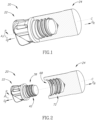
- FIGs. 1 and 2 showing a rotary cutting tool 20 of the type used for milling operations, specifically fast face milling, in accordance with embodiments of the subject matter of the present application.
- the rotary cutting tool 20 has a tool longitudinal axis L around which the tool rotates in a direction of rotation R.
- the rotary cutting tool 20 includes a replaceable cutting head 22 that has a head longitudinal axis A, around which the replaceable cutting head 22 rotates in the direction of rotation R.
- the head longitudinal axis A extends in the forward D F to rearward direction D R .
- the replaceable cutting head 22 can be typically made from cemented carbide.
- the rotary cutting tool 20 also includes a tool holder 24 having a holder longitudinal axis C.
- the tool holder 24 can be typically made from steel.
- the replaceable cutting head 22 can be removably retained in the tool holder 24 by means of a threaded coupling mechanism.
- a threaded coupling mechanism could possibly be advantageous for other types of rotary cutting operations than that stated hereinabove, such as, for example, reaming or drilling.
- forward and “rearward” refer to a relative position of the replaceable cutting head 22 to the tool holder 24 of the assembled rotary cutting tool 20, as seen in Fig. 1 .
- the terms “forward” and “rearward” may also be applied in a direction of the head longitudinal axis A towards the left and right, respectively, in Figs. 3 and 4 , and also in a direction of holder longitudinal axis C towards the left and right, respectively, in Figs. 5 and 6 .
- the replaceable cutting head 22 has a forward portion that forms a cutting portion 26 and a rearward portion that forms a mounting portion 28.
- the replaceable cutting head 22 can be formed from a unitary integral one-piece construction. This provides an advantage in that the replaceable cutting head 22 has no detachable cutting inserts (not shown).
- the cutting portion 26 includes at least one peripheral cutting edge 30.
- Each peripheral cutting edge 30 is formed at the intersection of a peripheral relief surface 32, and a peripheral rake surface 34.
- the peripheral relief surface 32 is located rotationally behind the peripheral cutting edge 30 and the peripheral rake surface 34 is located rotationally ahead of the peripheral cutting edge 30, both in respect to the direction of rotation R.
- the orientation of the peripheral cutting edge 30 allows metal cutting operations to be performed.
- the cutting portion 26 can include at least one flute 36 for evacuating chips (not shown) that are produced during the cutting operation.
- One flute 36 is associated to each peripheral cutting edge 30.
- the replaceable cutting head 22 can include one or more end cutting edges 30b at an end face 37 of the cutting portion 26. In this non-limiting example shown in the drawings, the replaceable cutting head 22 can include exactly two end cutting edges 30b. Each of the two end cutting edges 30b may have an associated side cutting edge 30a.
- the mounting portion 28 includes a male coupling member 38 that protrudes rearwardly from a head base surface 40.
- the head base surface 40 extends transversely with respect to the head longitudinal axis A and defines a boundary between the cutting portion 26 and the mounting portion 28. That is to say, the cutting portion 26 is formed forward of the head base surface 40 and the mounting portion 28 is formed rearward of the head base surface 40.
- the male coupling member 38 can be rigid.
- the head base surface 40 can be perpendicular to the head longitudinal axis A. The head base surface 40 is intended to abut a corresponding surface on the tool holder 24 when the rotary cutting tool 20 is in a locked position, as will be described hereinafter.
- the male coupling member 38 includes an external thread 42.
- the external thread 42 includes an external thread ridge 44 that extends helically about an external thread axis B.
- the external thread axis B is co-incident with the head longitudinal axis A.
- the external thread portion 42 and the replaceable cutting head 22 are co-axial.
- the external thread ridge 44 includes forward and rearward external flank surfaces 46, 48 and an external top surface 50 that extends therebetween.
- the forward and rearward external flank surfaces 46, 48 face in opposite axial directions D F , D R , with the forward external flank surface 46 facing in the forward direction D F and the rearward external flank surface 48 facing in the rearward direction D R .
- the forward and rearward external flank surfaces 46, 48 delimit an external thread groove 52.
- the external thread groove 52 extends helically about the external thread axis B and includes an external bottom surface 54.
- the external top surface 50 forms a plurality of external thread crests 56 and the external bottom surface 54 forms a plurality of external thread roots 58.
- the plurality of external thread crests 56 can be parallel to the external thread axis B and co-linear with each other.
- the plurality of external thread roots 58 can be parallel to the external thread axis B and co-linear with each other.
- the forward and rearward external flank surfaces 46, 48 can be inclined at an external flank angle ⁇ with respect to a radial plane perpendicular to the external thread axis B.
- the external flank angle ⁇ can be around 17°.
- the external thread 42 defines an external thread form 60 that can be trapezoidal.
- the external top surface 50 and external bottom surface 54 can smoothly transition into the forward and rearward external flank surfaces 46, 48, respectively, defining a radius.
- the external thread form 60 can be triangular.
- the external top surface 50 and external bottom surface 54 can form an edge.
- the plurality of external thread crests 56 define the major diameter and the plurality of external thread roots 58 define the minor diameter of the external thread 42, respectively.
- the external thread height H E can be constant.
- the external thread 42 can have approximately three turns.
- the external thread 42 is a straight thread. It should be appreciated that the term "straight thread” throughout the description and claims relates to a thread where the thread ridge extends about a cylinder and thus the thread crests are equidistant from the thread axis. Similarly, it should be appreciated that the term “tapered thread” throughout the description and claims relates to a thread where the thread ridge extends about a cone, whose surface tapers radially inwardly towards the thread axis in the rearward direction, and thus the thread crests decrease in distance from the thread axis in the rearward direction.
- the male coupling member 38 includes a forward bearing portion 62.
- the forward bearing portion 50 is located on the forward side of the external thread 42.
- the forward bearing portion 62 includes a forward head abutment surface 64 that tapers radially inwardly towards the head longitudinal axis A in a rearward direction D R . That is to say, the forward head abutment surface 64 has a conical shape facing radially outwards. It is noted that the forward head abutment surface 64 is intended to abut a corresponding surface on the tool holder 24 when the rotary cutting tool 20 is in a locked position, as will be described hereinafter.
- the tool holder 24 has a holder longitudinal axis C that extends in the forward D F to rearward direction D R .
- the tool holder 24 includes a female coupling member 68 that extends rearwardly from a holder forward surface 70.
- the holder forward surface 70 extends transversely with respect to the holder longitudinal axis C.
- the holder forward surface 70 can be perpendicular to the holder longitudinal axis C.
- the female coupling member 68 includes an internal thread 72.
- the internal thread 72 includes an internal thread ridge 74 that extends helically about an internal thread axis D.
- the internal thread axis D is co-incident with the holder longitudinal axis C.
- the internal thread portion 72 is co-axial with the tool holder 24.
- the internal thread ridge 74 includes forward and rearward internal flank surfaces 76, 78 and an internal top surface 80 that extends therebetween.
- the forward and rearward internal flank surfaces 76, 78 face in opposite axial directions D F , D R , with the forward internal flank surface 76 facing in the forward direction D F and the rearward internal flank surface 78 facing in the rearward direction D R .
- the forward and rearward internal flank surfaces 76, 78 delimit an internal thread groove 82.
- the internal thread groove 82 extends helically about the internal thread axis D and includes an internal bottom surface 84.
- the internal top surface 80 forms a plurality of internal thread crests 88 and the internal bottom surface 84 forms a plurality of internal thread roots 90.
- the plurality of internal thread crests 88 are parallel to the internal thread axis D and co-linear with each other.
- the plurality of internal thread roots 90 are parallel to the internal thread axis D and follow a pattern of decreasing distance therefrom in the rearward direction D R .
- the forward and rearward internal flank surfaces 76, 78 can be inclined at an internal flank angle ⁇ with respect to a radial plane perpendicular to the internal thread axis D.
- the internal flank angle ⁇ can be around 17°.
- the internal thread 72 defines an internal thread form 86 that can be trapezoidal. Referring now to Fig. 8 , the sides of the trapezium may not be equal in length.
- the internal top surface 80 and internal bottom surface 84 can smoothly transition into the forward and rearward internal flank surfaces 76, 78, respectively, defining a radius.
- the internal thread form 86 can be triangular.
- the internal top surface 80 and internal bottom surface 84 can form an edge.
- the plurality of internal thread crests 88 define the minor diameter and the plurality of internal thread roots 90 define the major diameter of the internal thread 72, respectively.
- the internal thread height H I can be constant, or increasing or decreasing in the rearward direction D R depending on which of the internal thread ridge 74 and internal thread groove 82 extend about a respective cone K In this non-limiting example shown in the drawings, the internal thread height H I decreases in the rearward direction
- the internal thread 72 can have approximately three turns.
- the internal thread 72 is a conical thread.
- conical thread throughout the description and claims relates to a thread where at least one of the thread ridge and the thread groove extend about a respective cone, whose surface tapers radially inwardly towards the thread axis in the rearward direction, and thus at least one of the thread crests and thread roots decrease in distance from the thread axis in the rearward direction.
- a conical thread may be formed by threading the hollow forward end of a cylindrical steel rod with an internal turning insert. As the steel rod rotates and moves in the axial direction to form the internal thread it also moves radially away from the 'static' cutting insert so that the thread has a conical configuration.
- the cone and the thread are co-axial. In Fig. 8 , the cone is defined by the points where the internal bottom surface 84 transitions into the rearward internal flank surface 78.
- At least one of the internal thread ridge 74 and the internal thread groove 82 can extend about a respective cone K having a cone angle ⁇ .
- the cone angle ⁇ is in the range of 0.02° ⁇ ⁇ ⁇ 1.6°.
- the cone angle ⁇ can be equal to exactly 0.8°.
- Only the internal thread groove 82 can extend about a respective cone K
- the internal thread ridge 74 can extend about a cylinder Y.
- the female coupling member 68 includes a forward supporting portion 92
- the forward supporting portion 80 is located on the forward side of the internal thread 72.
- the forward supporting portion 92 includes a forward holder abutment surface 94 that tapers radially inwardly towards the holder longitudinal axis C in a rearward direction D R . That is to say, the forward holder abutment surface 94 has a conical shape facing radially inwards.
- Assembly of the rotary cutting tool 20 is known, for example, from US 6,485,220 B2 , which is hereby incorporated by reference in its entirety. It is noted that the rotary cutting tool 20 is adjustable between a released position and a locked (or assembled) position.
- the male coupling member 38 is located outside of the female coupling member 68.
- the male coupling member 38 is removably retained in the female coupling member 68.
- the external and internal threads 42,72 threadingly engage each other.
- the forward head abutment surface 64 abuts the forward holder abutment surface 94.
- the rearwardly facing head base surface 40 can abut the forwardly facing holder forward surface 70.
- the rearward internal flank surface 78 can abut the forward external flank surface 46.
- the forward internal flank surface 76 can be spaced apart from the rearward external flank surface 48.
- the internal top surface 80 can be spaced apart from the external bottom surface 54.
- the internal bottom surface 84 can be spaced apart from the external top surface 50.
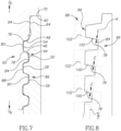
- FIG. 8 showing a schematic view of the internal thread form 86 of a conical internal thread 72.
- an imaginary internal thread form 96 of a straight internal thread and an imaginary external thread form 98 of a straight external thread, which are threadingly engaged with each other, are superimposed thereupon.
- the cone angle ⁇ of the internal thread 72 that forms the internal thread form 86 is exaggerated in order to clearly show the internal thread forms 86, 96 in relation to each other, and thus distances do not represent of true values.
- each turn of the internal thread form 86 is offset from the thread axis D by a distance that, by virtue of the internal thread 72 being conical, decreases as the internal thread 72 extends helically about the thread axis in the rearward direction D R .
- each ridge portion of the internal thread form 86 extends beyond (or stated differently, has a part that "overhangs") a corresponding ridge portion of the imaginary internal thread form 96 such that each rearward internal flank surface 78 is distanced from the respective imaginary rearward internal flank surface 100 by a flank distance E.
- the flank distance E increases in magnitude in the rearward direction D R . That is to say, the flank distance E increases in magnitude for successive thread turns in the rearward direction D R .
- each ridge portion of the internal thread form 86 extends over as to partly cover (i.e. overlaps) a corresponding ridge portion of the imaginary external thread form 98 such that each rearward internal flank surface 78 is distanced from the respective imaginary forward external flank surface 102 by the same flank distance E.
- FIG. 9 showing four diagrams showing the contact force distribution exerted on straight external threads that are threadingly engaged with straight and conical internal threads, respectively, when the rotary cutting tool is assembled and working.
- the lengths of the arrows represent the magnitude of the contact forces. It can be seen that the distribution of the contact forces, when the rotary cutting tools 20 are assembled and working, on a straight external thread threadingly coupled with a conical internal thread (the two diagrams on the right), are located further in the rearward direction D R compared with a straight internal thread threadingly engaged with a straight internal thread (the two diagrams on the left).
Landscapes
- Engineering & Computer Science (AREA)
- Mechanical Engineering (AREA)
- Milling Processes (AREA)
Applications Claiming Priority (2)
| Application Number | Priority Date | Filing Date | Title |
|---|---|---|---|
| US15/075,782 US10105771B2 (en) | 2016-03-21 | 2016-03-21 | Rotary cutting tool having tool holder with conical internal thread and replaceable cutting head with straight external thread, and said tool holder |
| PCT/IL2017/050259 WO2017163231A1 (en) | 2016-03-21 | 2017-03-01 | Rotary cutting tool having tool holder with conical internal thread and replaceable cutting head with straight external thread, and said tool holder |
Publications (2)
| Publication Number | Publication Date |
|---|---|
| EP3433042A1 EP3433042A1 (en) | 2019-01-30 |
| EP3433042B1 true EP3433042B1 (en) | 2025-01-15 |
Family
ID=58398232
Family Applications (1)
| Application Number | Title | Priority Date | Filing Date |
|---|---|---|---|
| EP17712853.5A Active EP3433042B1 (en) | 2016-03-21 | 2017-03-01 | Rotary cutting tool having tool holder with conical internal thread and replaceable cutting head with straight external thread |
Country Status (11)
| Country | Link |
|---|---|
| US (1) | US10105771B2 (https=) |
| EP (1) | EP3433042B1 (https=) |
| JP (1) | JP7154131B2 (https=) |
| KR (1) | KR102264414B1 (https=) |
| CN (1) | CN108778590B (https=) |
| BR (1) | BR112018067578B1 (https=) |
| CA (1) | CA3016387A1 (https=) |
| IL (1) | IL260857B (https=) |
| RU (1) | RU2726050C2 (https=) |
| TW (1) | TWI714720B (https=) |
| WO (1) | WO2017163231A1 (https=) |
Families Citing this family (11)
| Publication number | Priority date | Publication date | Assignee | Title |
|---|---|---|---|---|
| KR20180016342A (ko) * | 2015-06-12 | 2018-02-14 | 미쓰비시 마테리알 가부시키가이샤 | 테이퍼 엔드 밀 및 절삭 헤드 |
| US10335871B2 (en) * | 2016-04-12 | 2019-07-02 | Iscar, Ltd. | Replaceable face-milling head with integrally formed threaded shank-connector |
| DE102017127814A1 (de) * | 2017-11-24 | 2019-05-29 | Hartmetall-Werkzeugfabrik Paul Horn Gmbh | Werkzeug zur spanenden Bearbeitung eines Werkstücks |
| CN109434143B (zh) * | 2018-09-26 | 2020-03-10 | 厦门金鹭特种合金有限公司 | 一种头部交换式切削工具 |
| US11059109B2 (en) * | 2018-12-31 | 2021-07-13 | Iscar, Ltd. | Cutting head having torque transmission surfaces on a mounting protuberance and rotary cutting tool having such cutting head |
| US11446746B2 (en) | 2019-12-10 | 2022-09-20 | Iscar, Ltd. | Replaceable cutting head having back-tapered conical external thread and rotary cutting tool |
| US11376676B2 (en) | 2020-07-07 | 2022-07-05 | Iscar, Ltd. | Rotary cutting head having cutting edges extending past key actuating portion |
| US11426803B2 (en) * | 2020-09-08 | 2022-08-30 | Iscar, Ltd. | Replaceable cutting head having external thread with concavely curved root and rotary cutting tool |
| JP2022187086A (ja) * | 2021-06-07 | 2022-12-19 | 日本特殊陶業株式会社 | スパークプラグ |
| CN116252000A (zh) * | 2022-09-08 | 2023-06-13 | 湖北三环锻造有限公司 | 一种可调节锥度的刀柄、锥孔加工装置及其调平方法 |
| CN116060678A (zh) * | 2023-01-18 | 2023-05-05 | 株洲钻石切削刀具股份有限公司 | 一种具有多重径向夹持的模块式切削刀具 |
Citations (1)
| Publication number | Priority date | Publication date | Assignee | Title |
|---|---|---|---|---|
| US5169183A (en) * | 1987-05-12 | 1992-12-08 | Diamant Boart Stratabit S.A. | Threaded joint for drill rod elements |
Family Cites Families (38)
| Publication number | Priority date | Publication date | Assignee | Title |
|---|---|---|---|---|
| SU121327A1 (ru) * | 1959-02-02 | 1959-11-30 | К.М. Романов | Способ креплени хвостовых фрез и других подобных инструментов, устанавливаемых в конусе борштанги, например, горизонтально-расточного станка |
| US3762745A (en) * | 1972-04-03 | 1973-10-02 | Hughes Tool Co | Connection members with high torque carrying capacity |
| FR2359353A1 (fr) * | 1976-07-23 | 1978-02-17 | Vallourec | Joint pour tubes, notamment pour tubes petroliers |
| SU1349887A1 (ru) * | 1985-05-22 | 1987-11-07 | Московский станкостроительный завод "Красный пролетарий" им.А.И.Ефремова | Наборный режущий инструмент |
| JPS6252387U (https=) * | 1985-09-20 | 1987-04-01 | ||
| RU1807755C (ru) * | 1990-01-15 | 1995-01-09 | Сосульников Игорь Леонидович | Резьбовое соединение |
| JPH0648075B2 (ja) * | 1990-04-16 | 1994-06-22 | エスエムシー株式会社 | 管継手 |
| US5114286A (en) * | 1991-08-13 | 1992-05-19 | Calkins Donald W | Interchangeable tool alignment system |
| JPH09152069A (ja) * | 1995-11-28 | 1997-06-10 | Yoshitoshi:Kk | メカニカル継手 |
| US5695297A (en) * | 1996-09-11 | 1997-12-09 | Fenner, Inc. | Mounting device |
| IL136032A (en) | 2000-05-09 | 2003-12-10 | Iscar Ltd | Tool joint |
| US7431543B2 (en) * | 2002-02-15 | 2008-10-07 | Dihart Ag | Machine reamer |
| IL150013A (en) * | 2002-06-04 | 2007-06-17 | Gil Hecht | Rotary cutting tool |
| SE528299C2 (sv) * | 2004-09-24 | 2006-10-17 | Seco Tools Ab | Skärspets och skärverktyg med hållardel utformad som stympad konisk gänga |
| WO2006113760A2 (en) * | 2005-04-20 | 2006-10-26 | Tomm, Erwin | Threaded connector with interlock |
| CN2780386Y (zh) * | 2005-05-10 | 2006-05-17 | 王春良 | 内外螺纹卡盘 |
| IL172121A0 (en) | 2005-11-22 | 2009-02-11 | Joseph Pano | Cutting tool assembly |
| SE530043C2 (sv) * | 2006-04-20 | 2008-02-12 | Sandvik Intellectual Property | Verktyg för spånavskiljande bearbetning samt del därtill |
| SE532394C2 (sv) | 2007-06-04 | 2010-01-12 | Sandvik Intellectual Property | Verktyg för spånavskiljande bearbetning samt grundkropp härför |
| SE531746C2 (sv) | 2007-07-03 | 2009-07-28 | Seco Tools Ab | I flera delar utformad verktygsenhet och skärverktyg |
| EP2233233B1 (en) * | 2009-03-27 | 2017-04-26 | Mitsubishi Materials Corporation | Exchangeable cutting head and cutting tool having the same |
| JP5350149B2 (ja) * | 2009-09-07 | 2013-11-27 | ダイジ▲ェ▼ット工業株式会社 | 切削工具 |
| US9810029B2 (en) | 2011-01-26 | 2017-11-07 | Bly Ip Inc. | Drill string components resistant to jamming |
| DE102012100976B4 (de) * | 2012-02-07 | 2014-04-24 | Franz Haimer Maschinenbau Kg | Einschraubwerkzeug und Werkzeugaufnahme für ein derartiges Einschraubwerkzeug |
| US9802256B2 (en) * | 2012-02-07 | 2017-10-31 | Franz Haimer Maschinenbau Kg | Screw-in tool and tool holder for such a screw-in tool |
| EP2832481A4 (en) * | 2012-03-29 | 2015-08-12 | Hitachi Tool Eng | MACHINE HEAD, HOLDER AND CUTTING TOOL WITH REPLACEABLE TIP |
| DE102012104606B4 (de) * | 2012-05-29 | 2015-11-19 | Franz Haimer Maschinenbau Kg | Werkzeugaufnahme für ein Einschraubwerkzeug |
| DE102012107546A1 (de) * | 2012-08-17 | 2014-02-20 | Franz Haimer Maschinenbau Kg | Werkzeuganordnung |
| US20140056658A1 (en) * | 2012-08-24 | 2014-02-27 | Sumitomo Electric Hardmetal Corp. | Cutting tool with removable head |
| DE102013100939A1 (de) * | 2013-01-30 | 2014-07-31 | Franz Haimer Maschinenbau Kg | Werkzeugaufnahme für ein Einschraubwerkzeug |
| US9120164B2 (en) | 2013-04-29 | 2015-09-01 | Iscar, Ltd. | Cutting tool having a tool coupling with offset peripheral and central coupling threads and method of assembly thereof |
| US9643264B2 (en) | 2013-07-25 | 2017-05-09 | Kennametal Inc. | Coupling mechanism for cutting tool |
| US9643262B2 (en) * | 2013-07-25 | 2017-05-09 | Kennametal Inc. | Coupling mechanism for cutting tool |
| CN204195344U (zh) * | 2014-01-23 | 2015-03-11 | 上海新山田精密刀具有限公司 | 用于切削刀具和转轴刚性连接的刀柄 |
| CN203843263U (zh) * | 2014-02-28 | 2014-09-24 | 贵州劲锋精密工具有限公司 | 刀具夹紧装置 |
| US9889509B2 (en) | 2014-05-05 | 2018-02-13 | Kennametal Inc. | Cutter heads with improved coupling |
| CN106255564A (zh) * | 2014-05-08 | 2016-12-21 | 肯纳金属公司 | 用于切削工具的联接机构 |
| TWM517035U (zh) * | 2015-04-10 | 2016-02-11 | 呂春明 | 一體成型液靜壓導螺桿螺母 |
-
2016
- 2016-03-21 US US15/075,782 patent/US10105771B2/en active Active
-
2017
- 2017-02-10 TW TW106104525A patent/TWI714720B/zh not_active IP Right Cessation
- 2017-03-01 KR KR1020187026635A patent/KR102264414B1/ko active Active
- 2017-03-01 WO PCT/IL2017/050259 patent/WO2017163231A1/en not_active Ceased
- 2017-03-01 EP EP17712853.5A patent/EP3433042B1/en active Active
- 2017-03-01 JP JP2018540098A patent/JP7154131B2/ja active Active
- 2017-03-01 CA CA3016387A patent/CA3016387A1/en active Pending
- 2017-03-01 CN CN201780018830.9A patent/CN108778590B/zh active Active
- 2017-03-01 RU RU2018136881A patent/RU2726050C2/ru active
- 2017-03-01 BR BR112018067578-4A patent/BR112018067578B1/pt not_active IP Right Cessation
-
2018
- 2018-07-30 IL IL260857A patent/IL260857B/en unknown
Patent Citations (1)
| Publication number | Priority date | Publication date | Assignee | Title |
|---|---|---|---|---|
| US5169183A (en) * | 1987-05-12 | 1992-12-08 | Diamant Boart Stratabit S.A. | Threaded joint for drill rod elements |
Also Published As
| Publication number | Publication date |
|---|---|
| EP3433042A1 (en) | 2019-01-30 |
| CN108778590A (zh) | 2018-11-09 |
| JP7154131B2 (ja) | 2022-10-17 |
| WO2017163231A1 (en) | 2017-09-28 |
| TW201733716A (zh) | 2017-10-01 |
| RU2018136881A3 (https=) | 2020-05-22 |
| TWI714720B (zh) | 2021-01-01 |
| RU2726050C2 (ru) | 2020-07-08 |
| BR112018067578A2 (pt) | 2019-01-08 |
| RU2018136881A (ru) | 2020-04-22 |
| IL260857B (en) | 2022-02-01 |
| CA3016387A1 (en) | 2017-09-28 |
| US20170266738A1 (en) | 2017-09-21 |
| US10105771B2 (en) | 2018-10-23 |
| JP2019512401A (ja) | 2019-05-16 |
| CN108778590B (zh) | 2021-06-22 |
| KR20180125476A (ko) | 2018-11-23 |
| BR112018067578B1 (pt) | 2023-02-28 |
| KR102264414B1 (ko) | 2021-06-16 |
Similar Documents
| Publication | Publication Date | Title |
|---|---|---|
| EP3433042B1 (en) | Rotary cutting tool having tool holder with conical internal thread and replaceable cutting head with straight external thread | |
| EP2931461B1 (en) | Cutting tool and replaceable cutting head having spiral driven surfaces therefor | |
| CN102438782B (zh) | 旋转式切割工具 | |
| EP3334550B1 (en) | Replaceable cutting head and rotary cutting tool | |
| JP6056611B2 (ja) | 交換式切削ヘッド | |
| KR102222788B1 (ko) | 절삭날 위치의 조정 기구 및 날끝 교환식 절삭 공구 | |
| US10005136B2 (en) | Drill or drill head with burnishing margin | |
| EP4072760B1 (en) | Replaceable cutting head having back-tapered conical external thread and rotary cutting tool | |
| HK40069045A (en) | Replaceable cutting head having back-tapered conical external thread and rotary cutting tool | |
| JP6358306B2 (ja) | 交換式切削ヘッド |
Legal Events
| Date | Code | Title | Description |
|---|---|---|---|
| STAA | Information on the status of an ep patent application or granted ep patent |
Free format text: STATUS: UNKNOWN |
|
| STAA | Information on the status of an ep patent application or granted ep patent |
Free format text: STATUS: THE INTERNATIONAL PUBLICATION HAS BEEN MADE |
|
| PUAI | Public reference made under article 153(3) epc to a published international application that has entered the european phase |
Free format text: ORIGINAL CODE: 0009012 |
|
| STAA | Information on the status of an ep patent application or granted ep patent |
Free format text: STATUS: REQUEST FOR EXAMINATION WAS MADE |
|
| 17P | Request for examination filed |
Effective date: 20180921 |
|
| AK | Designated contracting states |
Kind code of ref document: A1 Designated state(s): AL AT BE BG CH CY CZ DE DK EE ES FI FR GB GR HR HU IE IS IT LI LT LU LV MC MK MT NL NO PL PT RO RS SE SI SK SM TR |
|
| AX | Request for extension of the european patent |
Extension state: BA ME |
|
| DAV | Request for validation of the european patent (deleted) | ||
| DAX | Request for extension of the european patent (deleted) | ||
| STAA | Information on the status of an ep patent application or granted ep patent |
Free format text: STATUS: EXAMINATION IS IN PROGRESS |
|
| 17Q | First examination report despatched |
Effective date: 20211207 |
|
| GRAP | Despatch of communication of intention to grant a patent |
Free format text: ORIGINAL CODE: EPIDOSNIGR1 |
|
| STAA | Information on the status of an ep patent application or granted ep patent |
Free format text: STATUS: GRANT OF PATENT IS INTENDED |
|
| INTG | Intention to grant announced |
Effective date: 20240826 |
|
| GRAS | Grant fee paid |
Free format text: ORIGINAL CODE: EPIDOSNIGR3 |
|
| GRAA | (expected) grant |
Free format text: ORIGINAL CODE: 0009210 |
|
| STAA | Information on the status of an ep patent application or granted ep patent |
Free format text: STATUS: THE PATENT HAS BEEN GRANTED |
|
| AK | Designated contracting states |
Kind code of ref document: B1 Designated state(s): AL AT BE BG CH CY CZ DE DK EE ES FI FR GB GR HR HU IE IS IT LI LT LU LV MC MK MT NL NO PL PT RO RS SE SI SK SM TR |
|
| P01 | Opt-out of the competence of the unified patent court (upc) registered |
Free format text: CASE NUMBER: APP_65098/2024 Effective date: 20241210 |
|
| REG | Reference to a national code |
Ref country code: CH Ref legal event code: EP Ref country code: GB Ref legal event code: FG4D |
|
| REG | Reference to a national code |
Ref country code: DE Ref legal event code: R096 Ref document number: 602017087329 Country of ref document: DE |
|
| REG | Reference to a national code |
Ref country code: IE Ref legal event code: FG4D |
|
| REG | Reference to a national code |
Ref country code: NL Ref legal event code: MP Effective date: 20250115 |
|
| PG25 | Lapsed in a contracting state [announced via postgrant information from national office to epo] |
Ref country code: NL Free format text: LAPSE BECAUSE OF FAILURE TO SUBMIT A TRANSLATION OF THE DESCRIPTION OR TO PAY THE FEE WITHIN THE PRESCRIBED TIME-LIMIT Effective date: 20250115 |
|
| PG25 | Lapsed in a contracting state [announced via postgrant information from national office to epo] |
Ref country code: RS Free format text: LAPSE BECAUSE OF FAILURE TO SUBMIT A TRANSLATION OF THE DESCRIPTION OR TO PAY THE FEE WITHIN THE PRESCRIBED TIME-LIMIT Effective date: 20250415 |
|
| PG25 | Lapsed in a contracting state [announced via postgrant information from national office to epo] |
Ref country code: FI Free format text: LAPSE BECAUSE OF FAILURE TO SUBMIT A TRANSLATION OF THE DESCRIPTION OR TO PAY THE FEE WITHIN THE PRESCRIBED TIME-LIMIT Effective date: 20250115 |
|
| PG25 | Lapsed in a contracting state [announced via postgrant information from national office to epo] |
Ref country code: PL Free format text: LAPSE BECAUSE OF FAILURE TO SUBMIT A TRANSLATION OF THE DESCRIPTION OR TO PAY THE FEE WITHIN THE PRESCRIBED TIME-LIMIT Effective date: 20250115 |
|
| PG25 | Lapsed in a contracting state [announced via postgrant information from national office to epo] |
Ref country code: ES Free format text: LAPSE BECAUSE OF FAILURE TO SUBMIT A TRANSLATION OF THE DESCRIPTION OR TO PAY THE FEE WITHIN THE PRESCRIBED TIME-LIMIT Effective date: 20250115 |
|
| REG | Reference to a national code |
Ref country code: LT Ref legal event code: MG9D |
|
| PG25 | Lapsed in a contracting state [announced via postgrant information from national office to epo] |
Ref country code: NO Free format text: LAPSE BECAUSE OF FAILURE TO SUBMIT A TRANSLATION OF THE DESCRIPTION OR TO PAY THE FEE WITHIN THE PRESCRIBED TIME-LIMIT Effective date: 20250415 Ref country code: IS Free format text: LAPSE BECAUSE OF FAILURE TO SUBMIT A TRANSLATION OF THE DESCRIPTION OR TO PAY THE FEE WITHIN THE PRESCRIBED TIME-LIMIT Effective date: 20250515 |
|
| REG | Reference to a national code |
Ref country code: AT Ref legal event code: MK05 Ref document number: 1759520 Country of ref document: AT Kind code of ref document: T Effective date: 20250115 |
|
| PG25 | Lapsed in a contracting state [announced via postgrant information from national office to epo] |
Ref country code: HR Free format text: LAPSE BECAUSE OF FAILURE TO SUBMIT A TRANSLATION OF THE DESCRIPTION OR TO PAY THE FEE WITHIN THE PRESCRIBED TIME-LIMIT Effective date: 20250115 |
|
| PG25 | Lapsed in a contracting state [announced via postgrant information from national office to epo] |
Ref country code: PT Free format text: LAPSE BECAUSE OF FAILURE TO SUBMIT A TRANSLATION OF THE DESCRIPTION OR TO PAY THE FEE WITHIN THE PRESCRIBED TIME-LIMIT Effective date: 20250515 Ref country code: LV Free format text: LAPSE BECAUSE OF FAILURE TO SUBMIT A TRANSLATION OF THE DESCRIPTION OR TO PAY THE FEE WITHIN THE PRESCRIBED TIME-LIMIT Effective date: 20250115 |
|
| PG25 | Lapsed in a contracting state [announced via postgrant information from national office to epo] |
Ref country code: GR Free format text: LAPSE BECAUSE OF FAILURE TO SUBMIT A TRANSLATION OF THE DESCRIPTION OR TO PAY THE FEE WITHIN THE PRESCRIBED TIME-LIMIT Effective date: 20250416 Ref country code: BG Free format text: LAPSE BECAUSE OF FAILURE TO SUBMIT A TRANSLATION OF THE DESCRIPTION OR TO PAY THE FEE WITHIN THE PRESCRIBED TIME-LIMIT Effective date: 20250115 |
|
| PG25 | Lapsed in a contracting state [announced via postgrant information from national office to epo] |
Ref country code: AT Free format text: LAPSE BECAUSE OF FAILURE TO SUBMIT A TRANSLATION OF THE DESCRIPTION OR TO PAY THE FEE WITHIN THE PRESCRIBED TIME-LIMIT Effective date: 20250115 |
|
| PG25 | Lapsed in a contracting state [announced via postgrant information from national office to epo] |
Ref country code: SE Free format text: LAPSE BECAUSE OF FAILURE TO SUBMIT A TRANSLATION OF THE DESCRIPTION OR TO PAY THE FEE WITHIN THE PRESCRIBED TIME-LIMIT Effective date: 20250115 |
|
| PG25 | Lapsed in a contracting state [announced via postgrant information from national office to epo] |
Ref country code: SM Free format text: LAPSE BECAUSE OF FAILURE TO SUBMIT A TRANSLATION OF THE DESCRIPTION OR TO PAY THE FEE WITHIN THE PRESCRIBED TIME-LIMIT Effective date: 20250115 |
|
| PG25 | Lapsed in a contracting state [announced via postgrant information from national office to epo] |
Ref country code: DK Free format text: LAPSE BECAUSE OF FAILURE TO SUBMIT A TRANSLATION OF THE DESCRIPTION OR TO PAY THE FEE WITHIN THE PRESCRIBED TIME-LIMIT Effective date: 20250115 |
|
| PG25 | Lapsed in a contracting state [announced via postgrant information from national office to epo] |
Ref country code: MC Free format text: LAPSE BECAUSE OF FAILURE TO SUBMIT A TRANSLATION OF THE DESCRIPTION OR TO PAY THE FEE WITHIN THE PRESCRIBED TIME-LIMIT Effective date: 20250115 |
|
| PG25 | Lapsed in a contracting state [announced via postgrant information from national office to epo] |
Ref country code: IT Free format text: LAPSE BECAUSE OF FAILURE TO SUBMIT A TRANSLATION OF THE DESCRIPTION OR TO PAY THE FEE WITHIN THE PRESCRIBED TIME-LIMIT Effective date: 20250115 |
|
| REG | Reference to a national code |
Ref country code: DE Ref legal event code: R097 Ref document number: 602017087329 Country of ref document: DE |
|
| PG25 | Lapsed in a contracting state [announced via postgrant information from national office to epo] |
Ref country code: EE Free format text: LAPSE BECAUSE OF FAILURE TO SUBMIT A TRANSLATION OF THE DESCRIPTION OR TO PAY THE FEE WITHIN THE PRESCRIBED TIME-LIMIT Effective date: 20250115 Ref country code: CZ Free format text: LAPSE BECAUSE OF FAILURE TO SUBMIT A TRANSLATION OF THE DESCRIPTION OR TO PAY THE FEE WITHIN THE PRESCRIBED TIME-LIMIT Effective date: 20250115 |
|
| REG | Reference to a national code |
Ref country code: CH Ref legal event code: H13 Free format text: ST27 STATUS EVENT CODE: U-0-0-H10-H13 (AS PROVIDED BY THE NATIONAL OFFICE) Effective date: 20251023 |
|
| PG25 | Lapsed in a contracting state [announced via postgrant information from national office to epo] |
Ref country code: RO Free format text: LAPSE BECAUSE OF FAILURE TO SUBMIT A TRANSLATION OF THE DESCRIPTION OR TO PAY THE FEE WITHIN THE PRESCRIBED TIME-LIMIT Effective date: 20250115 |
|
| PG25 | Lapsed in a contracting state [announced via postgrant information from national office to epo] |
Ref country code: SK Free format text: LAPSE BECAUSE OF FAILURE TO SUBMIT A TRANSLATION OF THE DESCRIPTION OR TO PAY THE FEE WITHIN THE PRESCRIBED TIME-LIMIT Effective date: 20250115 |
|
| PG25 | Lapsed in a contracting state [announced via postgrant information from national office to epo] |
Ref country code: LU Free format text: LAPSE BECAUSE OF NON-PAYMENT OF DUE FEES Effective date: 20250301 |
|
| PLBE | No opposition filed within time limit |
Free format text: ORIGINAL CODE: 0009261 |
|
| STAA | Information on the status of an ep patent application or granted ep patent |
Free format text: STATUS: NO OPPOSITION FILED WITHIN TIME LIMIT |
|
| REG | Reference to a national code |
Ref country code: BE Ref legal event code: MM Effective date: 20250331 |
|
| 26N | No opposition filed |
Effective date: 20251016 |
|
| GBPC | Gb: european patent ceased through non-payment of renewal fee |
Effective date: 20250415 |
|
| PG25 | Lapsed in a contracting state [announced via postgrant information from national office to epo] |
Ref country code: GB Free format text: LAPSE BECAUSE OF NON-PAYMENT OF DUE FEES Effective date: 20250415 |
|
| PG25 | Lapsed in a contracting state [announced via postgrant information from national office to epo] |
Ref country code: FR Free format text: LAPSE BECAUSE OF NON-PAYMENT OF DUE FEES Effective date: 20250315 |
|
| PG25 | Lapsed in a contracting state [announced via postgrant information from national office to epo] |
Ref country code: BE Free format text: LAPSE BECAUSE OF NON-PAYMENT OF DUE FEES Effective date: 20250331 |
|
| PG25 | Lapsed in a contracting state [announced via postgrant information from national office to epo] |
Ref country code: CH Free format text: LAPSE BECAUSE OF NON-PAYMENT OF DUE FEES Effective date: 20250331 |
|
| PG25 | Lapsed in a contracting state [announced via postgrant information from national office to epo] |
Ref country code: IE Free format text: LAPSE BECAUSE OF NON-PAYMENT OF DUE FEES Effective date: 20250301 |
|
| PGFP | Annual fee paid to national office [announced via postgrant information from national office to epo] |
Ref country code: DE Payment date: 20260216 Year of fee payment: 10 |