EP3431325B1 - Bodenelement zum induktiven laden - Google Patents
Bodenelement zum induktiven laden Download PDFInfo
- Publication number
- EP3431325B1 EP3431325B1 EP18178722.7A EP18178722A EP3431325B1 EP 3431325 B1 EP3431325 B1 EP 3431325B1 EP 18178722 A EP18178722 A EP 18178722A EP 3431325 B1 EP3431325 B1 EP 3431325B1
- Authority
- EP
- European Patent Office
- Prior art keywords
- floor element
- holding tray
- primary coil
- element according
- elements
- Prior art date
- Legal status (The legal status is an assumption and is not a legal conclusion. Google has not performed a legal analysis and makes no representation as to the accuracy of the status listed.)
- Active
Links
Images

Classifications
-
- H—ELECTRICITY
- H01—ELECTRIC ELEMENTS
- H01F—MAGNETS; INDUCTANCES; TRANSFORMERS; SELECTION OF MATERIALS FOR THEIR MAGNETIC PROPERTIES
- H01F6/00—Superconducting magnets; Superconducting coils
- H01F6/06—Coils, e.g. winding, insulating, terminating or casing arrangements therefor
-
- B—PERFORMING OPERATIONS; TRANSPORTING
- B60—VEHICLES IN GENERAL
- B60L—PROPULSION OF ELECTRICALLY-PROPELLED VEHICLES; SUPPLYING ELECTRIC POWER FOR AUXILIARY EQUIPMENT OF ELECTRICALLY-PROPELLED VEHICLES; ELECTRODYNAMIC BRAKE SYSTEMS FOR VEHICLES IN GENERAL; MAGNETIC SUSPENSION OR LEVITATION FOR VEHICLES; MONITORING OPERATING VARIABLES OF ELECTRICALLY-PROPELLED VEHICLES; ELECTRIC SAFETY DEVICES FOR ELECTRICALLY-PROPELLED VEHICLES
- B60L53/00—Methods of charging batteries, specially adapted for electric vehicles; Charging stations or on-board charging equipment therefor; Exchange of energy storage elements in electric vehicles
- B60L53/30—Constructional details of charging stations
- B60L53/34—Plug-like or socket-like devices specially adapted for contactless inductive charging of electric vehicles
-
- H—ELECTRICITY
- H02—GENERATION; CONVERSION OR DISTRIBUTION OF ELECTRIC POWER
- H02J—ELECTRIC POWER NETWORKS; CIRCUIT ARRANGEMENTS OR SYSTEMS FOR SUPPLYING OR DISTRIBUTING ELECTRIC POWER; SYSTEMS FOR STORING ELECTRIC ENERGY
- H02J7/00—Circuit arrangements for charging or discharging batteries or for supplying loads from batteries
- H02J7/70—Circuit arrangements for charging or discharging batteries or for supplying loads from batteries characterised by the mechanical construction
-
- H—ELECTRICITY
- H02—GENERATION; CONVERSION OR DISTRIBUTION OF ELECTRIC POWER
- H02J—ELECTRIC POWER NETWORKS; CIRCUIT ARRANGEMENTS OR SYSTEMS FOR SUPPLYING OR DISTRIBUTING ELECTRIC POWER; SYSTEMS FOR STORING ELECTRIC ENERGY
- H02J50/00—Circuit arrangements or systems for wireless supply or distribution of electric power
- H02J50/10—Circuit arrangements or systems for wireless supply or distribution of electric power using inductive coupling
-
- Y—GENERAL TAGGING OF NEW TECHNOLOGICAL DEVELOPMENTS; GENERAL TAGGING OF CROSS-SECTIONAL TECHNOLOGIES SPANNING OVER SEVERAL SECTIONS OF THE IPC; TECHNICAL SUBJECTS COVERED BY FORMER USPC CROSS-REFERENCE ART COLLECTIONS [XRACs] AND DIGESTS
- Y02—TECHNOLOGIES OR APPLICATIONS FOR MITIGATION OR ADAPTATION AGAINST CLIMATE CHANGE
- Y02T—CLIMATE CHANGE MITIGATION TECHNOLOGIES RELATED TO TRANSPORTATION
- Y02T10/00—Road transport of goods or passengers
- Y02T10/60—Other road transportation technologies with climate change mitigation effect
- Y02T10/70—Energy storage systems for electromobility, e.g. batteries
-
- Y—GENERAL TAGGING OF NEW TECHNOLOGICAL DEVELOPMENTS; GENERAL TAGGING OF CROSS-SECTIONAL TECHNOLOGIES SPANNING OVER SEVERAL SECTIONS OF THE IPC; TECHNICAL SUBJECTS COVERED BY FORMER USPC CROSS-REFERENCE ART COLLECTIONS [XRACs] AND DIGESTS
- Y02—TECHNOLOGIES OR APPLICATIONS FOR MITIGATION OR ADAPTATION AGAINST CLIMATE CHANGE
- Y02T—CLIMATE CHANGE MITIGATION TECHNOLOGIES RELATED TO TRANSPORTATION
- Y02T10/00—Road transport of goods or passengers
- Y02T10/60—Other road transportation technologies with climate change mitigation effect
- Y02T10/7072—Electromobility specific charging systems or methods for batteries, ultracapacitors, supercapacitors or double-layer capacitors
-
- Y—GENERAL TAGGING OF NEW TECHNOLOGICAL DEVELOPMENTS; GENERAL TAGGING OF CROSS-SECTIONAL TECHNOLOGIES SPANNING OVER SEVERAL SECTIONS OF THE IPC; TECHNICAL SUBJECTS COVERED BY FORMER USPC CROSS-REFERENCE ART COLLECTIONS [XRACs] AND DIGESTS
- Y02—TECHNOLOGIES OR APPLICATIONS FOR MITIGATION OR ADAPTATION AGAINST CLIMATE CHANGE
- Y02T—CLIMATE CHANGE MITIGATION TECHNOLOGIES RELATED TO TRANSPORTATION
- Y02T90/00—Enabling technologies or technologies with a potential or indirect contribution to GHG emissions mitigation
- Y02T90/10—Technologies relating to charging of electric vehicles
- Y02T90/12—Electric charging stations
-
- Y—GENERAL TAGGING OF NEW TECHNOLOGICAL DEVELOPMENTS; GENERAL TAGGING OF CROSS-SECTIONAL TECHNOLOGIES SPANNING OVER SEVERAL SECTIONS OF THE IPC; TECHNICAL SUBJECTS COVERED BY FORMER USPC CROSS-REFERENCE ART COLLECTIONS [XRACs] AND DIGESTS
- Y02—TECHNOLOGIES OR APPLICATIONS FOR MITIGATION OR ADAPTATION AGAINST CLIMATE CHANGE
- Y02T—CLIMATE CHANGE MITIGATION TECHNOLOGIES RELATED TO TRANSPORTATION
- Y02T90/00—Enabling technologies or technologies with a potential or indirect contribution to GHG emissions mitigation
- Y02T90/10—Technologies relating to charging of electric vehicles
- Y02T90/14—Plug-in electric vehicles
Definitions
- the invention relates to a floor element for inductive charging of an electric vehicle equipped with a secondary coil and to a vehicle parking space paved with concrete paving stones.
- So-called inductive charging is previously known for vehicles with an electric motor drive.
- energy is transferred in a contactless manner from a stationary primary coil in the floor to a secondary coil in the electric vehicle and stored in an energy storage device (battery) in the vehicle.
- US 2016/052398 A1 describes a channel-shaped recess following the course of the road, in which a plurality of primary coils are arranged one behind the other.
- the walls of this channel are made of concrete material and the channel is closed with a cover facing the road surface.
- the invention is based on the object of offering a particularly advantageous floor element for inductive charging or a corresponding vehicle parking space.
- the floor element according to the invention for inductive charging of an electric vehicle equipped with a secondary coil has a receiving shell with side walls made of a concrete material and a primary coil received in the receiving shell.
- the receiving shell made of concrete material forms a spatially defined receiving space for the primary coil.
- the primary coil can be stored in it safely and spatially exactly. In addition, it is protected from mechanical and weather-related influences.
- the cradle is prefabricated so that it can be installed quickly and easily on site, e.g. in the area of a vehicle parking space.
- the floor element is particularly suitable for flush installation in a paved area.
- the receiving shell has a passage for a connecting cable of the primary coil.
- the primary coil can be supplied with electrical energy quickly and easily.
- the passage is designed as a bore through a side wall of the receiving shell.
- the receiving shell also has a cover which closes the receiving shell.
- the cover can be made of a concrete material. However, it is also possible to use a different material for the cover. In particular, a material can be used which weakens as little as possible the alternating magnetic field that forms between the primary coil and the secondary coil. The cover can also be made as thin as possible in order to keep the distance between the primary coil and the secondary coil as small as possible.
- the primary coil is encapsulated or glued to the receiving shell. In this way, the primary coil can be held in a particularly secure position in the holding shell.
- the receiving shell is designed as a hood-shaped receiving shell.
- the receiving shell has an upper side which covers the primary coil in the installed state (hood-shaped).
- the primary coil is in front mechanical and weather-related impairments protected.
- the floor element can be integrated into the surroundings in an optically inconspicuous manner.
- the receiving shell is constructed in several parts.
- the multi-part design may facilitate transport and installation on site.
- the receiving tray can be divided into four corner elements, which are assembled on site to form a receiving tray.
- the primary coil is then inserted into this receptacle and connected to the required electrical infrastructure via the connection cable.
- the receiving shell not only to consist of corner elements, but also of edge elements and possibly central elements, which are combined on site to form a receiving shell.
- the passage for the connection cable can be designed as a bore, but especially in the case of a multi-part receiving shell, the passage can also be between two adjacent elements of the receiving shell (e.g. between two adjacent corner elements, between two adjacent edge elements and / or between a corner and an edge element).
- the base element - more precisely the receiving shell - has a total of four cuboid projections on at least two opposite side walls.
- the dimensions of these extensions are here adapted to the dimensions of paving stones, which can be laid flush with the floor element, so that a uniform joint pattern can be achieved.
- the dimensions of the cuboid extensions are selected in such a way that they correspond to the dimensions of the concrete paving stones used for paving the area in which the floor element is installed. In this way, the floor element in a visually appealing way paved area (e.g. a paved vehicle parking space) can be integrated or incorporated.
- Fig. 1 shows a perspective view of a floor element 1 for inductive charging.
- the floor element 1 consists of a receiving shell 2 and a primary coil 3 and is designed to be installed in the floor in the area of a vehicle parking space.
- the primary coil 3 is in Fig. 1 shown in dashed lines and is positioned inside the receiving shell 2, ie received in the receiving shell 2.
- the primary coil 3 has a connection cable 4 which is led out of the receiving shell 2 through a passage designed as a bore.
- the receiving shell 2 is made of a concrete material and has a cuboid outer shape.
- the primary coil 3 here is understood to mean not only the electronic component “primary coil”, but the entire assembly which, in addition to the electronic component, also has the necessary subordinate auxiliary components and possibly a casing or shell.
- Fig. 2 shows a sectional view through the in Fig. 1 illustrated floor element 1.
- the receiving shell 2 has side walls 5 and 7 and an underside 8 made of concrete material.
- a lid 9 closes the receiving shell 2, so that a closed receiving space is formed in which the primary coil 3 is received.
- the dimensions of the receiving space are adapted to the external dimensions of the primary coil 3.
- the primary coil 3 - and thus also the receiving space within the receiving shell 2 - has a cuboid shape.
- the shape of the receiving space would then likewise be designed in the form of a disk or flat cylinder.
- Fig. 3 shows a sectional view through a further base element 11.
- the receiving tray 2 used here does not differ from that in FIGS. 1 to 2 shown. Only the cover 9 was omitted. Instead, the primary coil 3 is embedded in a potting compound 12.
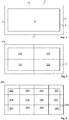
- Fig. 4 shows a plan view of the receiving tray 2 from FIGS. 1 to 3 .
- the receiving shell 2 has a total of four side walls 6, 7, 13 and 14 and an underside 8.
- a passage 5 designed as a bore is formed in the side wall 6.
- a connection cable 4 of the primary coil 3 can be passed through the passage 5.
- the receiving shell 2 is formed in one piece, ie in one piece from a concrete material, and can be a prefabricated concrete molding.
- Fig. 5 shows a multi-part receiving shell 102.
- the multi-part receiving shell 102 consists of a total of four corner elements 103.
- the four corner elements 103 are each formed separately from one another as a concrete block element and together form the receiving shell 102.
- Fig. 6 shows a further multi-part receiving shell 202.
- the multi-part receiving shell 202 consists of a total of four corner elements 203, six edge elements 204 and two center elements 206. All elements of the receiving shell 202 are each formed separately from one another as concrete block elements and together form the receiving shell 202.
- the passage 205 for implementation a connecting cable 4 is formed between a corner element 203 and an edge element 204. This shows more precisely in Fig. 6 Corner element 203 shown at the bottom right has a recess in its edge area, which serves as a passage 205.
- Both the one-piece receiving shell 2 and the multi-part receiving shells 102 and 202 are made of concrete material and have a receiving space in which the primary coil 3 can be stored safely and precisely.
- the passage 5 or 205 ensures a simple supply option with electrical energy.
- the floor element 1 or 11 can be installed flush with a paved surface in a simple manner.
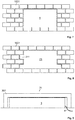
- Fig. 7 shows a section of an area paved with concrete paving stones 1001.
- the floor element 1 is integrated flush into the paved surface.
- the floor element 1 has a cuboid external shape.
- the paved area can be a vehicle parking space, for example.
- Fig. 8 shows a section of a further area paved with concrete paving stones 1001. This in Fig. 8 The floor element 21 shown is also installed flush with the concrete paving stones 1001 and has a total of four cuboid projections 211.
- the extensions 211 are formed on two opposite side walls of the receiving shell. The dimensions of the extensions 211 are adapted to the dimensions of the concrete paving stones 1001 in such a way that a uniform joint pattern can be achieved.
- Fig. 9 shows a bottom element 31 which has a receiving shell 302 which is designed in the shape of a hood.
- the hood-shaped receiving shell 302 encloses the primary coil 3, so that the primary coil is protected from the side and from above.
- the connection cable 4 is in the in Fig. 9 embodiment shown in the underground.
- This in Fig. 9 bottom element 31 shown is open at the bottom.
- an additional element for example analogous to the cover 9).
Landscapes
- Engineering & Computer Science (AREA)
- Power Engineering (AREA)
- Transportation (AREA)
- Mechanical Engineering (AREA)
- Electric Propulsion And Braking For Vehicles (AREA)
- Charge And Discharge Circuits For Batteries Or The Like (AREA)
Description
- Die Erfindung betrifft ein Bodenelement zum induktiven Laden eines mit einer Sekundärspule ausgestatteten Elektrofahrzeugs sowie einen mit Betonpflastersteinen gepflasterten Fahrzeugstellplatz.
- Für Fahrzeuge mit einem Elektromotorantrieb ist das sogenannte induktive Laden vorbekannt. Bei diesem wird kontaktlos Energie von einer stationär im Boden angebrachten Primärspule auf eine im Elektrofahrzeug angebrachten Sekundärspule übertragen und in einer Energiespeichervorrichtung (Akkubatterie) des Fahrzeugs gespeichert.
-
US 2016/052398 A1 beschreibt eine kanalförmige, dem Straßenverlauf folgende Vertiefung, in der eine Mehrzahl von hintereinander angeordneten Primärspulen angeordnet ist. Die Wände dieses Kanals sind aus Betonwerkstoff und verschlossen ist der Kanal mit einem der Fahrbahnoberfläche zugewandten Deckel. - Die Internetveröffentlichungen Conny Eck: "Betonfertigteile mit induktiver Ladetechnik", 09.11.2015, abgerufen am 03.06.2019 unter http://web.archive.org/web/20160328195750/https://www.beton.org/aktuell/ne ws/details/betonfertigteile-mit-induktiver-ladetechnik, und Conny Eck: "Von der Leine gelassen", 31.12.2015, abgerufen am 03.06.2019 unter http://context.heidelbergcement.de/ausgabe_02_15/von-der-leine-gelassen.html beschreiben ein Bodenelement zum induktiven Laden eines mit einer Sekundärspule ausgestatteten Elektrofahrzeugs. Die Primärspule dieses Bodenelements wird in Beton eingegossen und nach dem Aushärten im Bereich einer Bushaltestelle eingebaut.
- Die Internetveröffentlichung "Schnell und kostengünstig - Rohbau aus Fertigteilen", 22.11.2011, abgerufen am 12.11.2019 unter https://www.t-online.de/heim-garten/bauen/id-51675658/schnell-und-kostenguenstigrohbau -aus-fertigteilen.html beschreibt, das Fertighäuser häufig aus Betonfertigteilen zusammengesetzt werden.
- Der Erfindung liegt die Aufgabe zugrunde, ein besonders vorteilhaftes Bodenelement zum induktiven Laden bzw. einen entsprechenden Fahrzeugstellplatz anzubieten.
- Die Aufgabe wird durch ein Bodenelement mit den Merkmalen des Anspruchs 1 bzw. durch einen Fahrzeugstellplatz mit den Merkmalen des Anspruchs 10 gelöst. Vorteilhafte Ausführungsformen sind in den Unteransprüchen beschrieben.
- Das erfindungsgemäße Bodenelement zum induktiven Laden eines mit einer Sekundärspule ausgestatteten Elektrofahrzeugs weist eine Aufnahmeschale mit Seitenwänden aus einem Betonwerkstoff und eine in der Aufnahmeschale aufgenommene Primärspule auf.
- Die Aufnahmeschale aus Betonwerkstoff bildet einen räumlich definierten Aufnahmeraum für die Primärspule. Die Primärspule kann darin sicher und räumlich exakt gelagert werden. Außerdem ist sie vor mechanischen und witterungsbedingten Beeinflussungen geschützt. Ferner ist die Aufnahmeschale vorgefertigt damit sie schnell und einfach vor Ort z.B. im Bereich eines Fahrzeugstellplatzes eingebaut werden kann.
- Insbesondere eignet sich das Bodenelement zum flächenbündigen Einbau in einen gepflasterten Bereich.
- Erfindungsgemäß weist die Aufnahmeschale einen Durchlass für ein Anschlusskabel der Primärspule auf. Auf diese Weise ist eine schnelle und unkomplizierte Versorgung der Primärspule mit elektrischer Energie möglich. In besonders vorteilhafter Weise ist der Durchlass als Bohrung durch eine Seitenwand der Aufnahmeschale ausgebildet. Dadurch kann das Anschlusskabel seitlich neben der Aufnahmeschale verlegt werden und in einem späteren Arbeitsschritt beispielsweise unter Betonpflastersteinen verdeckt werden.
- In einer weiteren vorteilhaften Ausführungsform weist die Aufnahmeschale ferner einen Deckel auf, welcher die Aufnahmeschale verschließt. Auf diese Weise kann die Primärspule besonders sicher vor mechanischen und witterungsbedingten Einflüssen geschützt werden. Der Deckel kann hierbei aus einem Betonwerkstoff gefertigt sein. Es ist jedoch auch möglich, einen anderen Werkstoff für den Deckel zu verwenden. Insbesondere kann ein Werkstoff verwendet werden, der das sich zwischen der Primarspule und der Sekundärspule ausbildende magnetische Wechselfeld möglichst wenig schwächt. Auch kann der Deckel möglichst dünn ausgebildet sein, um den Abstand zwischen der Primarspule und der Sekundärspule möglichst gering zu halten.
- In einer weiteren vorteilhaften Ausführungsform ist die Primärspule mit der Aufnahmeschale vergossen bzw. mit dieser verklebt. Auf diese Weise ist eine besonders lagesichere Aufnahme der Primärspule in der Aufnahmeschale möglich.
- In einer weiteren vorteilhaften Ausführungsform ist die Aufnahmeschale als haubenförmige Aufnahmeschale ausgebildet. Mit anderen Worten besitzt die Aufnahmeschale eine Oberseite, die die Primärspule im eingebauten Zustand (haubenförmig) überdeckt. Auf diese Weise ist die Primärspule vor mechanischen und witterungsbedingten Beeinträchtigungen geschützt. Außerdem kann das Bodenelement dadurch optisch unauffällig in die Umgebung integriert sein.
- Die Aufnahmeschale ist mehrteilig ausgebildet. Die mehrteilige Ausbildung erleichtert u. U. den Transport und den Einbau vor Ort. Insbesondere kann die Aufnahmeschale in vier Eckelemente unterteilt sein, die vor Ort zu einer Aufnahmeschale zusammengesetzt werden. In diese Aufnahmeschale wird anschließend die Primärspule eingelegt und über das Anschlusskabel an die benötigte elektrische Infrastruktur angeschlossen. In ähnlicher Weise ist es möglich, dass die Aufnahmeschale nicht nur aus Eckelementen, sondern auch aus Randelementen und ggf. Mittelelementen besteht, die vor Ort zu einer Aufnahmeschale kombiniert werden.
- Wie bereits oben beschrieben kann der Durchlass für das Anschlusskabel als Bohrung ausgebildet sein, insbesondere bei einer mehrteiligen Aufnahmeschale kann der Durchlass jedoch auch zwischen zwei benachbarten Elementen der Aufnahmeschale (z.B. zwischen zwei benachbarten Eckelementen, zwischen zwei benachbarten Randelementen und/oder zwischen einem Eck- und einem Randelement) ausgebildet sein.
- Das Bodenelement - genauer die Aufnahmeschale - weist insgesamt vier quaderförmige Fortsätze an mindestens zwei gegenüberliegenden Seitenwänden auf. Die Abmessungen dieser Fortsätze sind hierbei derart an die Abmessungen von Pflastersteinen, welche flächenbündig mit dem Bodenelement verlegbar sind, angepasst, dass ein gleichmäßiges Fugenbild erzielt werden kann. Mit anderen Worten sind die Abmessungen der quaderförmigen Fortsätze derart ausgewählt, dass diese mit den Abmessungen der zum Pflastern des Bereichs, in dem das Bodenelement eingebaut wird, verwendeten Betonpflastersteine korrespondieren. Auf diese Weise kann das Bodenelement auf optisch ansprechende Weise in eine gepflasterte Fläche (z.B. einen gepflasterten Fahrzeugstellplatz) integriert bzw. eingebunden werden.
- Die Erfindung ist anhand von Ausführungsbeispielen in den Zeichnungsfiguren weiter erläutert, wobei gleiche Bezugszeichen gleiche bzw. gleichwirkende Komponenten bezeichnen. Es zeigen:
- Fig. 1
- eine perspektivische Ansicht eines Bodenelements zum induktiven Laden;
- Fig. 2
- eine Schnittansicht des Bodenelements aus
Fig. 1 ; - Fig. 3
- eine Schnittansicht eines zweiten Bodenelements;
- Fig. 4
- eine Draufsicht auf die einstückige Aufnahmeschale aus
Fig. 1 ; - Fig. 5
- eine Draufsicht auf eine mehrteilige Aufnahmeschale;
- Fig. 6
- eine Draufsicht auf eine weitere mehrteilige Aufnahmeschale;
- Fig. 7
- eine Draufsicht auf eine mit Betonpflastersteinen gepflasterte Fläche, in der das Bodenelement aus
Fig. 1 flächenbündig integriert ist; - Fig. 8
- eine Draufsicht auf eine weitere mit Betonpflastersteinen gepflasterte Fläche, in der ein weiteres Bodenelement flächenbündig integriert ist; und
- Fig. 9
- eine Schnittansicht durch ein haubenförmiges Bodenelement.
-
Fig. 1 zeigt eine perspektivische Ansicht eines Bodenelements 1 zum induktiven Laden. Das Bodenelement 1 besteht aus einer Aufnahmeschale 2 und einer Primärspule 3 und ist dazu ausgelegt, im Bereich eines Fahrzeugstellplatzes in den Boden eingebaut zu werden. Die Primärspule 3 ist inFig. 1 gestrichelt dargestellt und ist innerhalb der Aufnahmeschale 2 positioniert, d.h. in die Aufnahmeschale 2 aufgenommen. Die Primärspule 3 weist ein Anschlusskabel 4 auf, das durch einen als Bohrung ausgebildeten Durchlass aus der Aufnahmeschale 2 herausgeführt ist. Die Aufnahmeschale 2 ist aus einem Betonwerkstoff gefertigt und besitzt eine quaderförmige Außenform. Unter der Primärspule 3 wird hierbei nicht nur das elektronische Bauteil "Primärspule" verstanden, sondern die gesamte Baugruppe, die neben dem elektronischen Bauteil auch die nötigen untergeordneten Hilfsbauteile und ggf. eine Ummantelung bzw. Hülle aufweist. -
Fig. 2 zeigt eine Schnittansicht durch das inFig. 1 dargestellte Bodenelement 1. Die Aufnahmeschale 2 weist Seitenwände 5 und 7 sowie eine Unterseite 8 aus Betonwerkstoff auf. Ein Deckel 9 verschließt die Aufnahmeschale 2, sodass ein abgeschlossener Aufnahmeraum gebildet wird, in dem die Primärspule 3 aufgenommen ist. Die Abmessungen des Aufnahmeraums sind hierbei an die Außenabmessungen der Primärspule 3 angepasst. In den vorliegend beschriebenen Ausführungsformen besitzt die Primärspule 3 - und damit auch der Aufnahmeraum innerhalb der Aufnahmeschale 2 - eine quaderförmige Form. Es ist jedoch auch möglich, eine scheiben- oder flachzylindrische Primärspule 3 zu verwenden. Die Form des Aufnahmeraums würde dann entsprechend ebenfalls scheiben- bzw. flachzylindrisch ausgebildet sein. -
Fig. 3 zeigt eine Schnittansicht durch ein weiteres Bodenelement 11. Die hierbei verwendete Aufnahmeschale 2 unterscheidet sich nicht von der inFig. 1 bis Fig. 2 gezeigten. Es wurde lediglich auf den Deckel 9 verzichtet. Stattdessen ist die Primärspule 3 in einer Vergussmasse 12 eingebettet. -
Fig. 4 zeigt eine Draufsicht auf die Aufnahmeschale 2 ausFig. 1 bis Fig. 3 . Die Aufnahmeschale 2 weist insgesamt vier Seitenwände 6, 7, 13 und 14 sowie eine Unterseite 8 auf. In der Seitenwand 6 ist ein als Bohrung ausgebildeter Durchgang 5 ausgebildet. Durch den Durchgang 5 kann ein Anschlusskabel 4 der Primärspule 3 geführt werden. Die Aufnahmeschale 2 ist einstückig, d.h. einteilig aus einem Betonwerkstoff, ausgebildet und kann ein vorgefertigtes Betonformteil sein. -
Fig. 5 zeigt eine mehrteilige Aufnahmeschale 102. Die mehrteilige Aufnahmeschale 102 besteht aus insgesamt vier Eckelementen 103. Die vier Eckelemente 103 sind jeweils separat voneinander als Betonsteinelement ausgebildet und bilden zusammen die Aufnahmeschale 102. -
Fig. 6 zeigt eine weitere mehrteilige Aufnahmeschale 202. Die mehrteilige Aufnahmeschale 202 besteht aus insgesamt vier Eckelementen 203, sechs Randelementen 204 und zwei Mittenelementen 206. Sämtliche Elemente der Aufnahmeschale 202 sind jeweils separat voneinander als Betonsteinelement ausgebildet und bilden zusammen die Aufnahmeschale 202. Der Durchlass 205 zur Durchführung eines Anschlusskabels 4 ist zwischen einen Eckelement 203 und einem Randelemente 204 ausgebildet. Genauer weist das inFig. 6 rechts unten dargestellte Eckelement 203 in dessen Kantenbereich eine Ausnehmung auf, die als Durchlass 205 dient. - Sowohl die einstückige Aufnahmeschale 2 als auch die mehrteiligen Aufnahmeschalen 102 und 202 sind aus Betonwerkstoff gefertigt und weisen einen Aufnahmeraum auf, in den die Primärspule 3 sicher und exakt gelagert werden kann. Der Durchlass 5 bzw. 205 sorgt für eine einfache Versorgungsmöglichkeit mit elektrischer Energie. Außerdem kann das Bodenelement 1 bzw. 11 auf einfache Weise flächenbündig mit einer gepflasterten Fläche eingebaut werden.
-
Fig. 7 zeigt einen Ausschnitt einer mit Betonpflastersteinen 1001 gepflasterte Fläche. In die gepflasterte Fläche ist das Bodenelement 1 flächenbündig integriert. Das Bodenelement 1 weist eine quaderförmige Außenform auf. Die gepflasterte Fläche kann beispielsweise ein Fahrzeugstellplatz sein. -
Fig. 8 zeigt einen Ausschnitt einer weiteren mit Betonpflastersteinen 1001 gepflasterte Fläche. Das inFig. 8 dargestellte Bodenelement 21 ist ebenfalls flächenbündig mit den Betonpflastersteinen 1001 eingebaut und weist insgesamt vier quaderförmige Fortsätze 211 auf. Die Fortsätze 211 sind an zwei gegenüberliegenden Seitenwänden der Aufnahmeschale ausgebildet. Die Abmessungen der Fortsätze 211 sind derart an die Abmessungen der Betonpflastersteine 1001 angepasst, dass ein gleichmäßiges Fugenbild erzielt werden kann. -
Fig. 9 zeigt ein Bodenelement 31, welches eine Aufnahmeschale 302 aufweist, die haubenförmig ausgebildet ist. Die haubenförmige Aufnahmeschale 302 umschließt die Primärspule 3, sodass die Primärspule seitlich und von oben geschützt ist. Das Anschlusskabel 4 wird in der inFig. 9 dargestellten Ausführungsform im Untergrund geführt. Es ist jedoch auch möglich an der Seitenwand der Aufnahmeschale 302 einen Durchlass 5 vorzusehen. Das inFig. 9 dargestellte Bodenelement 31 ist nach unten offen. Es ist jedoch auch möglich, die Unterseite durch ein zusätzliches Element (z.B. analog zum Deckel 9) zu verschließen. -
- 1, 11, 21, 31
- Bodenelement
- 2, 102, 202, 302
- Aufnahmeschale
- 3
- Primärspule
- 4
- Anschlusskabel
- 5, 205
- Durchlass
- 6, 7
- Seitenwand
- 8
- Unterseite
- 9
- Deckel
- 12
- Vergussmasse
- 13, 14
- Seitenwand
- 103, 203
- Eckelement
- 204
- Randelement
- 206
- Mittenelement
- 211
- quaderförmiger Fortsatz
- 1001
- Betonpflasterstein
Claims (9)
- Bodenelement (1, 11, 21, 31) zum induktiven Laden eines mit einer Sekundärspule ausgestatteten Elektrofahrzeugs, wobei das Bodenelement (1, 11, 21, 31) aufweist:- eine Aufnahmeschale (2, 102, 202, 302) mit Seitenwänden (6, 7, 13, 14) aus einem Betonwerkstoff; und- eine in der Aufnahmeschale (2, 102, 202, 302) aufgenommene Primärspule (3), wobei- die Aufnahmeschale (102, 202) einen Durchlass (5, 205) für ein Anschlusskabel (4) der Primärspule (3) aufweist,dadurch gekennzeichnet, dass- die Aufnahmeschale (102, 202) eine vorgefertigte Aufnahmeschale (2, 102, 202, 302) ist;- genau eine Primärspule (3) in der Aufnahmeschale (102, 202) aufgenommen ist;- das Bodenelement (1, 11, 21, 31) insgesamt vier quaderförmige Fortsätze (211) an zwei gegenüberliegenden Seitenwänden aufweist;- die Aufnahmeschale (102, 202) mehrteilig ausgebildet ist;- die Aufnahmeschale (102, 202) vier, jeweils separat voneinander als Betonsteinelement ausgebildete Eckelemente (103, 203) aufweist; und- die Abmessungen der Fortsätze mit Abmessungen von Pflastersteinen, welche flächenbündig mit dem Bodenelement verlegbar sind, korrespondieren.
- Bodenelement nach Anspruch 1, wobei der Durchlass (5) als Bohrung, insbesondere als Bohrung durch eine Seitenwand (6), ausgebildet ist.
- Bodenelement nach einem der vorhergehenden Ansprüche ferner aufweisend einen Deckel (9), welcher die Aufnahmeschale (2) verschließt.
- Bodenelement nach Anspruch 3, wobei der Deckel (9) aus einem Betonwerkstoff gefertigt ist.
- Bodenelement nach einem der vorhergehenden Ansprüche, wobei die Primärspule (3) mit der Aufnahmeschale (102, 202) vergossen und/oder verklebt ist.
- Bodenelement nach einem der vorhergehenden Ansprüche, wobei die Aufnahmeschale (202) Randelemente (204) aufweist.
- Bodenelement nach einem der vorhergehenden Ansprüche, wobei die Aufnahmeschale (202) Mittenelement (206) aufweist.
- Bodenelement nach einem der vorhergehenden Ansprüche, wobei der Durchlass (205) zwischen benachbarten Eckelementen (203) und/oder Randelementen (204) ausgebildet ist.
- Mit Betonpflastersteinen gepflasterter Fahrzeugstellplatz, in dem das Bodenelement (1, 11, 21, 31) nach einem der vorhergehenden Ansprüche flächenbündig integriert ist.
Priority Applications (1)
| Application Number | Priority Date | Filing Date | Title |
|---|---|---|---|
| PL18178722T PL3431325T3 (pl) | 2017-07-18 | 2018-06-20 | Element podłogowy do ładowania indukcyjnego |
Applications Claiming Priority (1)
| Application Number | Priority Date | Filing Date | Title |
|---|---|---|---|
| DE202017104271.5U DE202017104271U1 (de) | 2017-07-18 | 2017-07-18 | Bodenelement zum induktiven Laden |
Publications (2)
| Publication Number | Publication Date |
|---|---|
| EP3431325A1 EP3431325A1 (de) | 2019-01-23 |
| EP3431325B1 true EP3431325B1 (de) | 2021-01-13 |
Family
ID=62715889
Family Applications (1)
| Application Number | Title | Priority Date | Filing Date |
|---|---|---|---|
| EP18178722.7A Active EP3431325B1 (de) | 2017-07-18 | 2018-06-20 | Bodenelement zum induktiven laden |
Country Status (6)
| Country | Link |
|---|---|
| EP (1) | EP3431325B1 (de) |
| DE (1) | DE202017104271U1 (de) |
| DK (1) | DK3431325T3 (de) |
| ES (1) | ES2863902T3 (de) |
| HU (1) | HUE053789T2 (de) |
| PL (1) | PL3431325T3 (de) |
Families Citing this family (2)
| Publication number | Priority date | Publication date | Assignee | Title |
|---|---|---|---|---|
| DE102019202553A1 (de) * | 2019-02-26 | 2020-08-27 | Universität Stuttgart | Vorrichtung zum induktiven Laden von Elektrofahrzeugen |
| DE102020212391A1 (de) | 2020-09-30 | 2022-03-31 | Mahle International Gmbh | Fahrbahn-Deckenplatte für eine induktive Baugruppe |
Family Cites Families (1)
| Publication number | Priority date | Publication date | Assignee | Title |
|---|---|---|---|---|
| US9796272B2 (en) * | 2014-08-25 | 2017-10-24 | Bryan Richards | Road bearing for electric vehicle connection |
-
2017
- 2017-07-18 DE DE202017104271.5U patent/DE202017104271U1/de not_active Expired - Lifetime
-
2018
- 2018-06-20 PL PL18178722T patent/PL3431325T3/pl unknown
- 2018-06-20 EP EP18178722.7A patent/EP3431325B1/de active Active
- 2018-06-20 DK DK18178722.7T patent/DK3431325T3/da active
- 2018-06-20 HU HUE18178722A patent/HUE053789T2/hu unknown
- 2018-06-20 ES ES18178722T patent/ES2863902T3/es active Active
Non-Patent Citations (3)
| Title |
|---|
| ANONYMOUS: "Schnell und kostengünstig - Rohbau aus Fertigteilen", 22 November 2011 (2011-11-22), pages 1 - 4, XP055641796, Retrieved from the Internet <URL:https://www.t-online.de/heim-garten/bauen/id_51675658/schnell-und-kostenguenstig-rohbau-aus-fertigteilen.html> [retrieved on 20191112] * |
| CONNY ECK: "Betonfertigteile mit induktiver Ladetechnik", 9 November 2015 (2015-11-09), XP055593411, Retrieved from the Internet <URL:http://web.archive.org/web/20160328195750/https://www.beton.org/aktuell/news/details/betonfertigteile-mit-induktiver-ladetechnik/> [retrieved on 20190603] * |
| CONNY ECK: "Von der Leine gelassen", 31 December 2015 (2015-12-31), XP055593634, Retrieved from the Internet <URL:http://context.heidelbergcement.de/ausgabe_02_15/von-der-leine-gelassen.html> [retrieved on 20190603] * |
Also Published As
| Publication number | Publication date |
|---|---|
| ES2863902T3 (es) | 2021-10-13 |
| HUE053789T2 (hu) | 2021-07-28 |
| PL3431325T3 (pl) | 2021-08-16 |
| DK3431325T3 (da) | 2021-04-12 |
| DE202017104271U1 (de) | 2018-10-24 |
| EP3431325A1 (de) | 2019-01-23 |
Similar Documents
| Publication | Publication Date | Title |
|---|---|---|
| EP3639335B1 (de) | Ladestation | |
| EP1947347B2 (de) | Pumpenaggregat | |
| DE102012202472B4 (de) | Vorrichtung zur kontaktlosen Übertragung von Energie auf eine korrespondierende Vorrichtung | |
| EP2081792B1 (de) | Verkleidungselement mit integrierter empfangseinheit zur berührungslosen übertragung von elektrischer energie und verfahren zu seiner herstellung | |
| EP2543773A1 (de) | Schachtdeckel | |
| DE102011004834A1 (de) | Ladeeinrichtung für ein Elektrofahrzeug nebst Herstellungsverfahren | |
| EP3607635B1 (de) | Verfahren zum herstellen eines systems zur induktiven übertragung von energie an ein mobilteil und vorrichtung zur durchführung des verfahrens | |
| EP3438366A1 (de) | Betonfertigdeckenteil für ein parkhaus und verfahren zur herstellung | |
| DE202016101962U1 (de) | Elektroinstallationsgehäuse zur Aufnahme einer elektrotechnischen Einrichtung in einem Betonteil | |
| DE202007008481U1 (de) | Ölwanne für eine Brennkraftmaschine-Getriebe-Einheit | |
| EP3431325A1 (de) | Bodenelement zum induktiven laden | |
| DE102011005758A1 (de) | Kraftfahrzeugschloss | |
| EP2009769A2 (de) | Wicklungsträger für einen Elektromotor mit einzelnen Spulenwicklungen | |
| DE102021206893A1 (de) | Bodenbaugruppe für eine induktive Ladevorrichtung | |
| DE102015122535A1 (de) | Schalungseinrichtung, Schalungssystem, Einbausystem sowie ein Verfahren zur Herstellung eines Bodens | |
| EP1376805B1 (de) | Unterflur-Bodendose | |
| EP3645335A1 (de) | Spuleneinrichtung für ein kraftfahrzeug, insbesondere für einen kraftwagen | |
| EP2608364B1 (de) | Elektrischer Antriebsmotor | |
| DE4324058A1 (de) | Hohlkörper für die Elektroinstallation | |
| DE102007039171A1 (de) | Verfahren zur Montage bzw. zum Einbringen eines Hohlkörpers in eine Betonwand oder Betondecke | |
| DE202012004001U1 (de) | Höhenverstellbare Vorrichtung zur Aufnahme von im Erdreich im Bereich von Straßen, Gehwegen oder dgl. angeordneten Armaturen | |
| DE102019104375B4 (de) | System zur Positionierung einer Einrichtung, Kanalsystem und Verfahren zur Ladung eines zur induktiven Ladung eingerichteten Gegenstands | |
| WO2024002509A1 (de) | Bordstein-, pflasterstein- oder randstein-ladevorrichtung zum laden eines energiespeichers eines elektrisch angetriebenen fahrzeugs | |
| EP3370316B1 (de) | Installationsdose mit magnethalterung | |
| EP1797261B1 (de) | Vorrichtung zum betätigen eines schlosses in einem fahrzeug |
Legal Events
| Date | Code | Title | Description |
|---|---|---|---|
| PUAI | Public reference made under article 153(3) epc to a published international application that has entered the european phase |
Free format text: ORIGINAL CODE: 0009012 |
|
| STAA | Information on the status of an ep patent application or granted ep patent |
Free format text: STATUS: THE APPLICATION HAS BEEN PUBLISHED |
|
| AK | Designated contracting states |
Kind code of ref document: A1 Designated state(s): AL AT BE BG CH CY CZ DE DK EE ES FI FR GB GR HR HU IE IS IT LI LT LU LV MC MK MT NL NO PL PT RO RS SE SI SK SM TR |
|
| AX | Request for extension of the european patent |
Extension state: BA ME |
|
| RIC1 | Information provided on ipc code assigned before grant |
Ipc: H02J 50/10 20160101ALI20181129BHEP Ipc: B60L 11/18 20060101AFI20181129BHEP Ipc: H01F 6/06 20060101ALI20181129BHEP |
|
| STAA | Information on the status of an ep patent application or granted ep patent |
Free format text: STATUS: REQUEST FOR EXAMINATION WAS MADE |
|
| 17P | Request for examination filed |
Effective date: 20190221 |
|
| RBV | Designated contracting states (corrected) |
Designated state(s): AL AT BE BG CH CY CZ DE DK EE ES FI FR GB GR HR HU IE IS IT LI LT LU LV MC MK MT NL NO PL PT RO RS SE SI SK SM TR |
|
| STAA | Information on the status of an ep patent application or granted ep patent |
Free format text: STATUS: EXAMINATION IS IN PROGRESS |
|
| 17Q | First examination report despatched |
Effective date: 20190611 |
|
| REG | Reference to a national code |
Ref country code: DE Ref legal event code: R079 Ref document number: 502018003633 Country of ref document: DE Free format text: PREVIOUS MAIN CLASS: B60L0011180000 Ipc: B60L0053340000 |
|
| GRAP | Despatch of communication of intention to grant a patent |
Free format text: ORIGINAL CODE: EPIDOSNIGR1 |
|
| STAA | Information on the status of an ep patent application or granted ep patent |
Free format text: STATUS: GRANT OF PATENT IS INTENDED |
|
| RIC1 | Information provided on ipc code assigned before grant |
Ipc: H02J 7/00 20060101ALI20200824BHEP Ipc: B60L 53/34 20190101AFI20200824BHEP Ipc: H01F 6/06 20060101ALI20200824BHEP |
|
| INTG | Intention to grant announced |
Effective date: 20200930 |
|
| GRAS | Grant fee paid |
Free format text: ORIGINAL CODE: EPIDOSNIGR3 |
|
| GRAA | (expected) grant |
Free format text: ORIGINAL CODE: 0009210 |
|
| STAA | Information on the status of an ep patent application or granted ep patent |
Free format text: STATUS: THE PATENT HAS BEEN GRANTED |
|
| AK | Designated contracting states |
Kind code of ref document: B1 Designated state(s): AL AT BE BG CH CY CZ DE DK EE ES FI FR GB GR HR HU IE IS IT LI LT LU LV MC MK MT NL NO PL PT RO RS SE SI SK SM TR |
|
| REG | Reference to a national code |
Ref country code: GB Ref legal event code: FG4D Free format text: NOT ENGLISH |
|
| REG | Reference to a national code |
Ref country code: CH Ref legal event code: EP |
|
| REG | Reference to a national code |
Ref country code: DE Ref legal event code: R096 Ref document number: 502018003633 Country of ref document: DE |
|
| REG | Reference to a national code |
Ref country code: IE Ref legal event code: FG4D Free format text: LANGUAGE OF EP DOCUMENT: GERMAN |
|
| REG | Reference to a national code |
Ref country code: AT Ref legal event code: REF Ref document number: 1354309 Country of ref document: AT Kind code of ref document: T Effective date: 20210215 |
|
| REG | Reference to a national code |
Ref country code: DK Ref legal event code: T3 Effective date: 20210406 |
|
| REG | Reference to a national code |
Ref country code: NL Ref legal event code: FP |
|
| REG | Reference to a national code |
Ref country code: SE Ref legal event code: TRGR |
|
| REG | Reference to a national code |
Ref country code: SK Ref legal event code: T3 Ref document number: E 36915 Country of ref document: SK |
|
| REG | Reference to a national code |
Ref country code: NO Ref legal event code: T2 Effective date: 20210113 |
|
| REG | Reference to a national code |
Ref country code: LT Ref legal event code: MG9D |
|
| REG | Reference to a national code |
Ref country code: HU Ref legal event code: AG4A Ref document number: E053789 Country of ref document: HU |
|
| PG25 | Lapsed in a contracting state [announced via postgrant information from national office to epo] |
Ref country code: LT Free format text: LAPSE BECAUSE OF FAILURE TO SUBMIT A TRANSLATION OF THE DESCRIPTION OR TO PAY THE FEE WITHIN THE PRESCRIBED TIME-LIMIT Effective date: 20210113 Ref country code: PT Free format text: LAPSE BECAUSE OF FAILURE TO SUBMIT A TRANSLATION OF THE DESCRIPTION OR TO PAY THE FEE WITHIN THE PRESCRIBED TIME-LIMIT Effective date: 20210513 Ref country code: BG Free format text: LAPSE BECAUSE OF FAILURE TO SUBMIT A TRANSLATION OF THE DESCRIPTION OR TO PAY THE FEE WITHIN THE PRESCRIBED TIME-LIMIT Effective date: 20210413 Ref country code: HR Free format text: LAPSE BECAUSE OF FAILURE TO SUBMIT A TRANSLATION OF THE DESCRIPTION OR TO PAY THE FEE WITHIN THE PRESCRIBED TIME-LIMIT Effective date: 20210113 Ref country code: GR Free format text: LAPSE BECAUSE OF FAILURE TO SUBMIT A TRANSLATION OF THE DESCRIPTION OR TO PAY THE FEE WITHIN THE PRESCRIBED TIME-LIMIT Effective date: 20210414 Ref country code: FI Free format text: LAPSE BECAUSE OF FAILURE TO SUBMIT A TRANSLATION OF THE DESCRIPTION OR TO PAY THE FEE WITHIN THE PRESCRIBED TIME-LIMIT Effective date: 20210113 |
|
| PG25 | Lapsed in a contracting state [announced via postgrant information from national office to epo] |
Ref country code: RS Free format text: LAPSE BECAUSE OF FAILURE TO SUBMIT A TRANSLATION OF THE DESCRIPTION OR TO PAY THE FEE WITHIN THE PRESCRIBED TIME-LIMIT Effective date: 20210113 Ref country code: LV Free format text: LAPSE BECAUSE OF FAILURE TO SUBMIT A TRANSLATION OF THE DESCRIPTION OR TO PAY THE FEE WITHIN THE PRESCRIBED TIME-LIMIT Effective date: 20210113 |
|
| PG25 | Lapsed in a contracting state [announced via postgrant information from national office to epo] |
Ref country code: IS Free format text: LAPSE BECAUSE OF FAILURE TO SUBMIT A TRANSLATION OF THE DESCRIPTION OR TO PAY THE FEE WITHIN THE PRESCRIBED TIME-LIMIT Effective date: 20210513 |
|
| REG | Reference to a national code |
Ref country code: ES Ref legal event code: FG2A Ref document number: 2863902 Country of ref document: ES Kind code of ref document: T3 Effective date: 20211013 |
|
| REG | Reference to a national code |
Ref country code: DE Ref legal event code: R097 Ref document number: 502018003633 Country of ref document: DE |
|
| PG25 | Lapsed in a contracting state [announced via postgrant information from national office to epo] |
Ref country code: SM Free format text: LAPSE BECAUSE OF FAILURE TO SUBMIT A TRANSLATION OF THE DESCRIPTION OR TO PAY THE FEE WITHIN THE PRESCRIBED TIME-LIMIT Effective date: 20210113 Ref country code: EE Free format text: LAPSE BECAUSE OF FAILURE TO SUBMIT A TRANSLATION OF THE DESCRIPTION OR TO PAY THE FEE WITHIN THE PRESCRIBED TIME-LIMIT Effective date: 20210113 |
|
| PLBE | No opposition filed within time limit |
Free format text: ORIGINAL CODE: 0009261 |
|
| STAA | Information on the status of an ep patent application or granted ep patent |
Free format text: STATUS: NO OPPOSITION FILED WITHIN TIME LIMIT |
|
| PG25 | Lapsed in a contracting state [announced via postgrant information from national office to epo] |
Ref country code: RO Free format text: LAPSE BECAUSE OF FAILURE TO SUBMIT A TRANSLATION OF THE DESCRIPTION OR TO PAY THE FEE WITHIN THE PRESCRIBED TIME-LIMIT Effective date: 20210113 |
|
| 26N | No opposition filed |
Effective date: 20211014 |
|
| PG25 | Lapsed in a contracting state [announced via postgrant information from national office to epo] |
Ref country code: AL Free format text: LAPSE BECAUSE OF FAILURE TO SUBMIT A TRANSLATION OF THE DESCRIPTION OR TO PAY THE FEE WITHIN THE PRESCRIBED TIME-LIMIT Effective date: 20210113 Ref country code: MC Free format text: LAPSE BECAUSE OF FAILURE TO SUBMIT A TRANSLATION OF THE DESCRIPTION OR TO PAY THE FEE WITHIN THE PRESCRIBED TIME-LIMIT Effective date: 20210113 |
|
| PG25 | Lapsed in a contracting state [announced via postgrant information from national office to epo] |
Ref country code: SI Free format text: LAPSE BECAUSE OF FAILURE TO SUBMIT A TRANSLATION OF THE DESCRIPTION OR TO PAY THE FEE WITHIN THE PRESCRIBED TIME-LIMIT Effective date: 20210113 |
|
| PG25 | Lapsed in a contracting state [announced via postgrant information from national office to epo] |
Ref country code: IE Free format text: LAPSE BECAUSE OF NON-PAYMENT OF DUE FEES Effective date: 20210620 |
|
| PG25 | Lapsed in a contracting state [announced via postgrant information from national office to epo] |
Ref country code: IS Free format text: LAPSE BECAUSE OF FAILURE TO SUBMIT A TRANSLATION OF THE DESCRIPTION OR TO PAY THE FEE WITHIN THE PRESCRIBED TIME-LIMIT Effective date: 20210513 |
|
| P01 | Opt-out of the competence of the unified patent court (upc) registered |
Effective date: 20230509 |
|
| PG25 | Lapsed in a contracting state [announced via postgrant information from national office to epo] |
Ref country code: CY Free format text: LAPSE BECAUSE OF FAILURE TO SUBMIT A TRANSLATION OF THE DESCRIPTION OR TO PAY THE FEE WITHIN THE PRESCRIBED TIME-LIMIT Effective date: 20210113 |
|
| PG25 | Lapsed in a contracting state [announced via postgrant information from national office to epo] |
Ref country code: MK Free format text: LAPSE BECAUSE OF FAILURE TO SUBMIT A TRANSLATION OF THE DESCRIPTION OR TO PAY THE FEE WITHIN THE PRESCRIBED TIME-LIMIT Effective date: 20210113 |
|
| PG25 | Lapsed in a contracting state [announced via postgrant information from national office to epo] |
Ref country code: MT Free format text: LAPSE BECAUSE OF FAILURE TO SUBMIT A TRANSLATION OF THE DESCRIPTION OR TO PAY THE FEE WITHIN THE PRESCRIBED TIME-LIMIT Effective date: 20210113 |
|
| PGFP | Annual fee paid to national office [announced via postgrant information from national office to epo] |
Ref country code: DK Payment date: 20250626 Year of fee payment: 8 |
|
| PGFP | Annual fee paid to national office [announced via postgrant information from national office to epo] |
Ref country code: NO Payment date: 20250627 Year of fee payment: 8 |
|
| PGFP | Annual fee paid to national office [announced via postgrant information from national office to epo] |
Ref country code: NL Payment date: 20250626 Year of fee payment: 8 Ref country code: LU Payment date: 20250626 Year of fee payment: 8 Ref country code: BE Payment date: 20250626 Year of fee payment: 8 |
|
| PGFP | Annual fee paid to national office [announced via postgrant information from national office to epo] |
Ref country code: FR Payment date: 20250626 Year of fee payment: 8 |
|
| PGFP | Annual fee paid to national office [announced via postgrant information from national office to epo] |
Ref country code: AT Payment date: 20250627 Year of fee payment: 8 |
|
| PGFP | Annual fee paid to national office [announced via postgrant information from national office to epo] |
Ref country code: SE Payment date: 20250626 Year of fee payment: 8 |
|
| PGFP | Annual fee paid to national office [announced via postgrant information from national office to epo] |
Ref country code: ES Payment date: 20250718 Year of fee payment: 8 |
|
| PGFP | Annual fee paid to national office [announced via postgrant information from national office to epo] |
Ref country code: DE Payment date: 20250626 Year of fee payment: 8 |
|
| PGFP | Annual fee paid to national office [announced via postgrant information from national office to epo] |
Ref country code: PL Payment date: 20250707 Year of fee payment: 8 Ref country code: IT Payment date: 20250626 Year of fee payment: 8 |
|
| PGFP | Annual fee paid to national office [announced via postgrant information from national office to epo] |
Ref country code: HU Payment date: 20250711 Year of fee payment: 8 Ref country code: GB Payment date: 20250724 Year of fee payment: 8 |
|
| PGFP | Annual fee paid to national office [announced via postgrant information from national office to epo] |
Ref country code: CH Payment date: 20250724 Year of fee payment: 8 |
|
| PGFP | Annual fee paid to national office [announced via postgrant information from national office to epo] |
Ref country code: CZ Payment date: 20250710 Year of fee payment: 8 |
|
| PGFP | Annual fee paid to national office [announced via postgrant information from national office to epo] |
Ref country code: SK Payment date: 20250710 Year of fee payment: 8 |
|
| PG25 | Lapsed in a contracting state [announced via postgrant information from national office to epo] |
Ref country code: TR Free format text: LAPSE BECAUSE OF FAILURE TO SUBMIT A TRANSLATION OF THE DESCRIPTION OR TO PAY THE FEE WITHIN THE PRESCRIBED TIME-LIMIT Effective date: 20210113 |