EP3427770A1 - Mécanisme de cathéter - Google Patents
Mécanisme de cathéter Download PDFInfo
- Publication number
- EP3427770A1 EP3427770A1 EP18186035.4A EP18186035A EP3427770A1 EP 3427770 A1 EP3427770 A1 EP 3427770A1 EP 18186035 A EP18186035 A EP 18186035A EP 3427770 A1 EP3427770 A1 EP 3427770A1
- Authority
- EP
- European Patent Office
- Prior art keywords
- distal
- rotor
- catheter device
- pump
- catheter
- Prior art date
- Legal status (The legal status is an assumption and is not a legal conclusion. Google has not performed a legal analysis and makes no representation as to the accuracy of the status listed.)
- Pending
Links
Images


Classifications
-
- A—HUMAN NECESSITIES
- A61—MEDICAL OR VETERINARY SCIENCE; HYGIENE
- A61M—DEVICES FOR INTRODUCING MEDIA INTO, OR ONTO, THE BODY; DEVICES FOR TRANSDUCING BODY MEDIA OR FOR TAKING MEDIA FROM THE BODY; DEVICES FOR PRODUCING OR ENDING SLEEP OR STUPOR
- A61M60/00—Blood pumps; Devices for mechanical circulatory actuation; Balloon pumps for circulatory assistance
- A61M60/40—Details relating to driving
- A61M60/403—Details relating to driving for non-positive displacement blood pumps
- A61M60/419—Details relating to driving for non-positive displacement blood pumps the force acting on the blood contacting member being permanent magnetic, e.g. from a rotating magnetic coupling between driving and driven magnets
-
- A—HUMAN NECESSITIES
- A61—MEDICAL OR VETERINARY SCIENCE; HYGIENE
- A61M—DEVICES FOR INTRODUCING MEDIA INTO, OR ONTO, THE BODY; DEVICES FOR TRANSDUCING BODY MEDIA OR FOR TAKING MEDIA FROM THE BODY; DEVICES FOR PRODUCING OR ENDING SLEEP OR STUPOR
- A61M60/00—Blood pumps; Devices for mechanical circulatory actuation; Balloon pumps for circulatory assistance
- A61M60/10—Location thereof with respect to the patient's body
- A61M60/122—Implantable pumps or pumping devices, i.e. the blood being pumped inside the patient's body
- A61M60/126—Implantable pumps or pumping devices, i.e. the blood being pumped inside the patient's body implantable via, into, inside, in line, branching on, or around a blood vessel
- A61M60/13—Implantable pumps or pumping devices, i.e. the blood being pumped inside the patient's body implantable via, into, inside, in line, branching on, or around a blood vessel by means of a catheter allowing explantation, e.g. catheter pumps temporarily introduced via the vascular system
-
- A—HUMAN NECESSITIES
- A61—MEDICAL OR VETERINARY SCIENCE; HYGIENE
- A61M—DEVICES FOR INTRODUCING MEDIA INTO, OR ONTO, THE BODY; DEVICES FOR TRANSDUCING BODY MEDIA OR FOR TAKING MEDIA FROM THE BODY; DEVICES FOR PRODUCING OR ENDING SLEEP OR STUPOR
- A61M60/00—Blood pumps; Devices for mechanical circulatory actuation; Balloon pumps for circulatory assistance
- A61M60/20—Type thereof
- A61M60/205—Non-positive displacement blood pumps
- A61M60/216—Non-positive displacement blood pumps including a rotating member acting on the blood, e.g. impeller
- A61M60/237—Non-positive displacement blood pumps including a rotating member acting on the blood, e.g. impeller the blood flow through the rotating member having mainly axial components, e.g. axial flow pumps
-
- A—HUMAN NECESSITIES
- A61—MEDICAL OR VETERINARY SCIENCE; HYGIENE
- A61M—DEVICES FOR INTRODUCING MEDIA INTO, OR ONTO, THE BODY; DEVICES FOR TRANSDUCING BODY MEDIA OR FOR TAKING MEDIA FROM THE BODY; DEVICES FOR PRODUCING OR ENDING SLEEP OR STUPOR
- A61M60/00—Blood pumps; Devices for mechanical circulatory actuation; Balloon pumps for circulatory assistance
- A61M60/80—Constructional details other than related to driving
- A61M60/802—Constructional details other than related to driving of non-positive displacement blood pumps
- A61M60/804—Impellers
- A61M60/806—Vanes or blades
- A61M60/808—Vanes or blades specially adapted for deformable impellers, e.g. expandable impellers
-
- A—HUMAN NECESSITIES
- A61—MEDICAL OR VETERINARY SCIENCE; HYGIENE
- A61M—DEVICES FOR INTRODUCING MEDIA INTO, OR ONTO, THE BODY; DEVICES FOR TRANSDUCING BODY MEDIA OR FOR TAKING MEDIA FROM THE BODY; DEVICES FOR PRODUCING OR ENDING SLEEP OR STUPOR
- A61M60/00—Blood pumps; Devices for mechanical circulatory actuation; Balloon pumps for circulatory assistance
- A61M60/80—Constructional details other than related to driving
- A61M60/802—Constructional details other than related to driving of non-positive displacement blood pumps
- A61M60/81—Pump housings
-
- A—HUMAN NECESSITIES
- A61—MEDICAL OR VETERINARY SCIENCE; HYGIENE
- A61M—DEVICES FOR INTRODUCING MEDIA INTO, OR ONTO, THE BODY; DEVICES FOR TRANSDUCING BODY MEDIA OR FOR TAKING MEDIA FROM THE BODY; DEVICES FOR PRODUCING OR ENDING SLEEP OR STUPOR
- A61M60/00—Blood pumps; Devices for mechanical circulatory actuation; Balloon pumps for circulatory assistance
- A61M60/80—Constructional details other than related to driving
- A61M60/802—Constructional details other than related to driving of non-positive displacement blood pumps
- A61M60/818—Bearings
- A61M60/825—Contact bearings, e.g. ball-and-cup or pivot bearings
-
- A—HUMAN NECESSITIES
- A61—MEDICAL OR VETERINARY SCIENCE; HYGIENE
- A61M—DEVICES FOR INTRODUCING MEDIA INTO, OR ONTO, THE BODY; DEVICES FOR TRANSDUCING BODY MEDIA OR FOR TAKING MEDIA FROM THE BODY; DEVICES FOR PRODUCING OR ENDING SLEEP OR STUPOR
- A61M60/00—Blood pumps; Devices for mechanical circulatory actuation; Balloon pumps for circulatory assistance
- A61M60/10—Location thereof with respect to the patient's body
- A61M60/122—Implantable pumps or pumping devices, i.e. the blood being pumped inside the patient's body
- A61M60/126—Implantable pumps or pumping devices, i.e. the blood being pumped inside the patient's body implantable via, into, inside, in line, branching on, or around a blood vessel
- A61M60/148—Implantable pumps or pumping devices, i.e. the blood being pumped inside the patient's body implantable via, into, inside, in line, branching on, or around a blood vessel in line with a blood vessel using resection or like techniques, e.g. permanent endovascular heart assist devices
-
- A—HUMAN NECESSITIES
- A61—MEDICAL OR VETERINARY SCIENCE; HYGIENE
- A61M—DEVICES FOR INTRODUCING MEDIA INTO, OR ONTO, THE BODY; DEVICES FOR TRANSDUCING BODY MEDIA OR FOR TAKING MEDIA FROM THE BODY; DEVICES FOR PRODUCING OR ENDING SLEEP OR STUPOR
- A61M60/00—Blood pumps; Devices for mechanical circulatory actuation; Balloon pumps for circulatory assistance
- A61M60/40—Details relating to driving
- A61M60/403—Details relating to driving for non-positive displacement blood pumps
- A61M60/408—Details relating to driving for non-positive displacement blood pumps the force acting on the blood contacting member being mechanical, e.g. transmitted by a shaft or cable
- A61M60/411—Details relating to driving for non-positive displacement blood pumps the force acting on the blood contacting member being mechanical, e.g. transmitted by a shaft or cable generated by an electromotor
- A61M60/414—Details relating to driving for non-positive displacement blood pumps the force acting on the blood contacting member being mechanical, e.g. transmitted by a shaft or cable generated by an electromotor transmitted by a rotating cable, e.g. for blood pumps mounted on a catheter
-
- A—HUMAN NECESSITIES
- A61—MEDICAL OR VETERINARY SCIENCE; HYGIENE
- A61M—DEVICES FOR INTRODUCING MEDIA INTO, OR ONTO, THE BODY; DEVICES FOR TRANSDUCING BODY MEDIA OR FOR TAKING MEDIA FROM THE BODY; DEVICES FOR PRODUCING OR ENDING SLEEP OR STUPOR
- A61M60/00—Blood pumps; Devices for mechanical circulatory actuation; Balloon pumps for circulatory assistance
- A61M60/80—Constructional details other than related to driving
- A61M60/802—Constructional details other than related to driving of non-positive displacement blood pumps
- A61M60/827—Sealings between moving parts
- A61M60/829—Sealings between moving parts having a purge fluid supply
Definitions
- the invention relates to a catheter device which is a miniaturized pump.
- Implantable blood pumps are increasingly being used to treat patients with severe heart disease. Such blood pumps have hitherto been intended primarily for long-term use. However, blood pumps are also being developed that are designed for short-term cardiac support and can be used minimally invasively. Medical goals are the relief and recovery of the heart or the bridging up to a possible heart transplantation.
- the breadth of the field of application of such pumps depends on the one hand on the simplicity of the introduction into the body, on the other hand on the realizable technical properties and in particular on the reliably realizable operating time of the available pump systems. Ideally, such a short-term blood pump should be percutaneously-intravascular without any surgical intervention.
- the output of the left ventricle is significantly reduced.
- the reduced coronary supply can lead to irreversible heart failure.
- the pumping function of the left ventricle should be partially or largely taken over and the coronary supply improved.
- heart surgery such a system can be used left and right ventricular and replace a heart-lung machine.
- a percutaneous intravascular implantable system that has been clinically important has been the intra-aortic balloon pump (IABP).
- the intra-aortic balloon pump or intra-aortic counter-pulsation is a mechanical system that is also used to support the pumping power of the heart in patients with cardiogenic shock.
- a catheter with a cylindrically shaped plastic balloon is advanced over the groin into the thoracic aorta (thoracic aorta) so that the balloon lies below the exit of the left clavicular artery (subclavian artery).
- the balloon is inflated rhythmically with an external pump with each heart action in diastole with 30-40 cm 3 of helium and drained again in systole.
- the balloon pump improves the circulation of the heart muscle and also of all other organs.
- the achievable hemodynamic improvement is very limited, since due to the design principle of IABP no active blood delivery takes place.
- the aorta below the left ventricle is closed and thus the blood ejected from the heart is pushed back and redistributed, thus also into the coronary arteries. There is no increase in blood flow.
- the suction port of the pump is placed retrograde over the aortic valve in the left ventricle.
- the pump rotor is located at the end of a cannula in the upper descending aorta and is driven by an external motor.
- Disadvantage of the system is that the transfemoral implantation is only possible surgically via a femoral artery and possibly by a Graftankopplung due to the large diameter of the rotor.
- the axial pump has a flexible compressible tube which forms the pump housing.
- the tube is a radially compressible rotor.
- the drive shaft of the rotor passes through a catheter.
- the catheter can be used together with the tube and the rotor in a cover tube be involved.
- the radial compressibility of the components allows the realization of a puncture diameter that is justifiable for percutaneous implantation using the Seldinger technique. Due to the development in the cardiovascular system, a relatively large pump diameter of 10 to 14 mm can be provided. This reduces the rotor speed and thus the mechanical stress of the components.
- the blood pump is an axial pump located within a catheter tube, at the end of which a balloon is provided which can be inflated to deploy the pump sheath and close the flow path leading past the pump, thereby closing the pump in the blood vessel fasten.
- a balloon is provided which can be inflated to deploy the pump sheath and close the flow path leading past the pump, thereby closing the pump in the blood vessel fasten.
- it is provided to arrange a cup-shaped end of the catheter in a tubular guide catheter, to retract it and to unfold in this way the cup-like end.
- the pump has a drive part and a pump part that are so small in diameter that they can be pushed through a blood vessel.
- the pump part is followed by a flexible cannula.
- the cannula can be widened to a diameter which is greater than that of the drive part or of the pump part.
- the cannula is set in the constricted state in which it has a small diameter. It is widened in the blood vessel so that it offers a lower flow resistance for the blood to be pumped.
- the artificial heart has a pump section and a drive section for driving the pump section.
- the pump section is relatively small and serves to receive an axial flow pump.
- the axial flow pump is designed as a screw pump.
- Various embodiments of screw pumps are provided.
- EP 0 364 293 A2 is a catheter with integrated blood pump described.
- a flexible rim extends over a tubular portion of the catheter and contacts the walls of the aorta, thus ensuring that all blood within the aorta flows through the pump.
- the flexible expandable rim spaces the pump from the aortic valve.
- the catheter device includes a drive shaft connected to a motor and a rotor attached to the drive shaft at the distal end portion.
- the rotor has a frame structure formed of a helical restriction frame and rotor struts extending radially inwardly from the restriction frame.
- the rotor struts are secured to the drive shaft with their ends remote from the bounding box.
- Between the limiting frame and the drive shaft extends an elastic covering.
- the frame structure is formed of an elastic material such that the rotor unfolds automatically after forced compression.
- the rotor Due to the frame structure of the rotor with boundary frame and rotor struts, the rotor is very stable, yet foldable and can be compressed to almost any small diameter. Due to the fact that, in principle, an almost arbitrarily long design of the rotor in the longitudinal direction and radial direction is possible, the rotor can be optimized depending on the available space with regard to a maximum delivery capacity. It is thus possible to optimally adjust the delivery rate for each application.
- the rotor is compressible such that it can be introduced into the body with a puncture needle via a puncture having a diameter of approximately 9 French.
- a rotor diameter is achieved, which is many times larger than the diameter of the rotor in the compressed state. As a result, a high flow rate is achieved.
- the rotor Due to the framework-like construction of the boundary frame and rotor struts, the rotor is given a high degree of rigidity, which allows the rotor to be rotated at high speeds without being unbalanced.
- a prototype of this catheter device could be operated for several hours to deliver a liquid at a speed of about 32,000 rpm.
- the frame structure of the rotor is made of a shape memory material, e.g. Nitinol, formed.
- the rotor can be brought to a temperature at which the shape memory material softens.
- a rotor made of nitinol is compressed at a temperature of about 0 ° C.
- the shape memory material solidifies again and unfolds. As a rule, it is not possible to non-destructively compress the rotor again without cooling down.
- the elastic covering between the limiting frame and the drive shaft is preferably made of a polymer coating, such as e.g. PU, PE, PP, silicone or parylene formed.
- the rotor is surrounded by a tubular pump section of a pump housing.
- the pump housing is formed of a grid whose openings are closed at least in the region of the pump section by means of an elastic covering.
- Such a pump housing can with a be formed small gap distance from the rotor, which set optimal flow conditions and the flow rate can be further optimized.
- the grid of the pump housing is preferably formed of a shape memory material which is compressible together with the rotor.
- the pump housing protects the rotor from external influences.
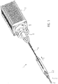
- FIG. 1 1 shows a catheter device 1.
- the catheter device 1 according to the invention represents a pump.
- the catheter device 1 has a pump head 3 at a distal end 2.
- the pump head 3 has a rotor 3.2 for conveying a medium in the conveying direction 5, which is connected to a drive shaft 4.
- the conveying direction 5 is directed from the distal end 2 to a proximal end 6.
- a motor 7 is arranged at the distance from the pump head 3 proximal end 6.
- the drive shaft 4 is surrounded by a catheter shaft 8 and connected by a clutch 9 frictionally connected to the motor 7.
- the pump head 3 comprises a butt plate 10 at the distal end, the rotor 3.2 arranged on the drive shaft 4, a pump housing 3.1 and an outflow tube 18.
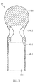
- the butt plate 10 is formed from a ball 10.1 with an attached cylindrical portion 10.2.
- the butt plate 10 is made of stainless steel, for example ( Fig.2 . Figure 3 ).
- the butt plate 10 could also be formed of polyethylene PE, polypropylene PP, polyetheretherketone PEEK, polyvinyl chloride PVC, Teflon PTFE, acrylic, epoxy, polyurethane PU, carbon fiber, coated materials, composite materials, PEBAX, a polyether block amide. In principle, all hemocompatible materials are suitable because only a small mechanical stress on this component occurs.
- the diameter of the ball 10.1 is approximately 3.2 mm.
- the cylindrical portion 10.2 is about 5.5 mm long and has a diameter of about 2.2 mm.
- the total length of the butt plate is about 7.0 mm.
- the cylindrical portion 10.2 has at its distal end, in the connection region to the ball 10.1 a transversely to the conveying direction 5 arranged through hole 10.3. Furthermore, the cylinder 10.2 has an axial bore 10.4, which extends from the proximal end of the cylindrical portion 10.2 to the ball 10.1 out, so that a communicating passage from the through hole 10.3 is formed to the proximal end of the butt plate 10. In the region of the axial bore 10.4, a step 10.5 is formed, so that the axial bore is widened in the direction of the proximal end.
- the through hole 10.3 on the one hand avoided that in the butt plate a blind hole is formed and on the other hand, the through hole allows the attachment of a thread that is helpful in compressing the pump head 3.
- the ball 10.1 of the butt plate 10 may also be provided a pigtail, a spiral, a meandering wire with ball point or an atraumatic fiber bundle.
- the butt plate is preferred because of its small size.
- the tip of the butt plate 10 is an atraumatic ball for the protection of the heart muscle (endocardium).
- About the butt plate 10 of the pump head 3 can be supported on the heart wall.
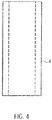
- a tubular catheter shaft piece 8.1 is inserted from the proximal end into the butt plate 10 to the step.
- the distal catheter shaft 8.1 is snugly received in the axial bore 10.4 and is fixed there ( Fig. 4 ).
- the distal catheter shaft 8.1 is made of polyurethane or other suitable material, in particular an elastic plastic material (eg PE, PVC, Teflon, elastomer) formed.
- the distal end of the distal catheter shaft 8.1 is connected to the butt plate 10.
- the compound can be formed as an adhesive bond by means of, for example, cyanoacrylate adhesive or it takes place as a welded, clamped or shrink-welded connection.
- the distal catheter shaft 8.1 forms a straight but slightly flexible connection between the butt plate 10 and the pump housing 3.1.
- the straight connection establishes a coaxiality of all components arranged in it (drive shaft, shaft protection, housing, connection socket).
- the distal catheter shaft 8.1 is used in conjunction with the butt plate 10 as a positioning aid of the pump head 3 when introduced into a vessel or the heart.
- the catheter shaft 8.1 in the present embodiment has a length of about 25 mm, an outer diameter of about 1.9 mm and an inner diameter of about 1.3 mm.
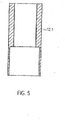
- a distal, tubular connector socket 12.1 provided ( Fig. 5 . Fig. 6 ).
- the distal connection bushing 12.1 has a larger inner diameter in the distal region than in the proximal region.
- the proximal end of the distal catheter shaft piece 8. 1 is snugly received and fixed.
- a distal connection section 3.1.1 of the pump housing 3.1 is accommodated in the proximal region of the distal connection bushing 12.1, a distal connection section 3.1.1 of the pump housing 3.1 is accommodated.
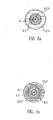
- the distal connection section 3.1.1 of the pump housing 3.1 is connected to the distal connection bushing 12.1 and the proximal end of the distal catheter shaft section 8.1 (FIG. Fig. 7a, Fig. 7b ).
- the distal connection socket 12.1 has a length of about 5 mm and an outer diameter of about 2.2 mm. In the distal region the diameter is approximately 2 mm and in the proximal region approximately 1.5 mm. The shorter the connection bushing, the lower the resulting stiffening.
- the distal and an analogous trained proximal connection socket 12.1, 12.2 are for example made of stainless steel, copper, brass, titanium or other suitable metal, polyethylene (PE), polypropylene (PP), Teflon (PTFE), PEBAX, a polyether block Amide, or other suitable material formed.
- the expandable or compressible pump housing 3.1 is a tubular grid structure 3.1.6 made of Nitinol or other suitable memory alloy or other shape memory material, such as plastic, iron alloy, copper alloy.
- the pump housing 3.1 is subdivided from distal to proximal into five sections (FIG. Fig. 8 ).
- the first distal section is a tubular distal connection section 3.1.1.
- a second section is a conically expanded in the conveying direction 5 suction 3.1.2.
- the suction section 3.1.2 is followed by a pump section 3.1.3.
- the tubular pump section 3.1.3 receives the rotor 3.2.
- the inner diameter of the pump section 3.1.3 in the expanded state is approximately 6.15 mm.
- An outlet section 3.1.4 conically narrows in the conveying direction 5 and forms the connection between the pump section 3.1.3 and a proximal connection section 3.1.5.
- the proximal connection section 3.1.5 is analogous to the distal connection section 3.1.1 tubular with a smaller diameter than the pump section 3.1.3.
- the pump housing 3.1 can be compressed so that it does not exceed a maximum diameter of less than 3 mm over the entire length.
- the lattice structure 3.1.6 of the pump housing 3.1 has openings 3.1.7 between the lattice struts (FIG. Fig. 8 . Fig. 9 ).
- the openings are formed as polygons 3.1.7, which are diamonds in the present embodiment.
- small diamonds 3.1.7.1 are provided in the pump section 3.1.3.
- the small diamonds 3.1.7.1 are summarized step by step to become larger diamonds. Adjacent to a small rhombus is a larger rhombus with double edge length arranged. This doubling of the edge length is repeated until the openings have the desired size.
- large diamonds 3.1.7.2 are provided, which have approximately four times the edge length of the small diamonds 3.1.7.1.
- the large diamonds 3.1.7.2 are summarized to smaller diamonds.
- medium-sized diamonds 3.1.7.3 are provided which have approximately twice the edge length of the small diamonds 3.1.7.1 ( Fig. 9 ).
- the formation of the openings 3.1.7 and the number of Einfielfachept can be arbitrary.
- the width of the lattice struts is increased.
- the strength of the lattice struts is kept approximately equal or even amplified to the larger diamonds out.
- the lattice structure 3.1.6 of the pump housing 3.1 is covered in the pump section 3.1.3 with a PU covering 3.1.8, whereby the grid openings are sealed liquid-tight.
- This covering or the sealing of the grid structure 3.1.6 can also be used e.g. by a PU tube which is arranged on the surface outside or inside, be formed.
- a covering other than PU such as e.g. PE, PP, silicone or parylene, as long as it meets the mechanical and geometric requirements.
- the performance parameters including blood damage to the pump can be controlled specifically.
- proximal connection section 3.1.5 of the pump housing 3.1 is received in the proximal connection socket 12.2 and connected thereto.
- proximal connection bushing 12.2 a tubular proximal catheter shaft section 8.2 is accommodated analogously to the distal connection bushing 12.1 and connected thereto ( Fig. 7a, Fig. 7b ).
- Fig. 7a, Fig. 7b The same types of connection already described above may be provided.
- a distal shaft protection 13.1 and a proximal shaft protection 13.2 are arranged in the axial direction ( Fig. 6 ).
- the distal and the proximal shaft protection 13.1, 13.2 are as Tube made of PU or another of the materials already listed above.
- the distal shaft protection 13.1 extends in the direction of conveyance 5 from just before the distal connection bush 12.1 to the distal end of the pump section 3.1.3 of the pump housing 3.1, i. to the rotor 3.2.
- the proximal shaft protector 13.2 extends from the proximal end of the rotor 3.2 to just past the proximal end of the proximal connection bushing 12.1.
- the distal and the proximal shaft protection 13.1, 13.2 are in the two areas in which they are disposed within the distal and the proximal connection sleeve 12.1, 12.2 and the distal and proximal catheter shaft 8.1, 8.2, connected to these.
- connection sockets 12.1, 12.2 together with the components arranged therein (shaft protection, pump housing, catheter shaft) a bearing area for the drive shaft 4.
- the connection sockets 12.1, 12.2 ensure the Achszentriertheit the drive shaft 4, in particular in the pump housing 3.1.
- the drive shaft 4 is arranged in the axial direction.
- the drive shaft 4 has three sections in the conveying direction 5.
- the rotor 3.2. is glued to the drive shaft.
- other non-positive connections such as welding or clamping can be provided.
- the proximal shaft protection 13.2 ( Fig. 2 . Fig. 6 ) separates, for protection against blood damage by the rotational movement of the drive shaft 4 and adhesion of blood components to the drive shaft 4, the proximal portion 4.3 of the drive shaft 4 spatially from the pumping medium. As a result, no shear forces build up. It comes to no direct interaction between the drive shaft 4 and the blood through the very small gap and only a minimal blood transport through this gap is possible.
- the distal and proximal shaft guards 13.1, 13.2 center and support the drive shaft 4 during operation and during the compression and expansion process.
- the drive shaft 4 is preferably formed of a plurality, in particular six wires (not shown) which are arranged left or right wound around a soul (not shown) formed.
- the outer diameter of the drive shaft 4 is approximately 0.48 mm.
- the drive shaft 4 can also have a different number of souls and wires and have a smaller or a larger diameter.
- the diameter of the drive shaft may be in the range of 0.3 mm to 1 mm, and is preferably about 0.4 mm to 0.6 mm.
- the smaller the diameter of the drive shaft the larger the rotational speed can be, because the smaller the diameter, the lower the speed with which the circumference of the drive shaft moves with respect to its surroundings.
- a high peripheral speed is problematic when the drive shaft is in contact with the environment.
- the catheter device is designed for speeds greater than 20,000 rpm and up to 40,000 rpm. Therefore, the diameter of the drive shaft 4 is made as small as possible, but so thick that it still has sufficient strength.
- the drive shaft 4 is wound left - is in the axial direction about the distal and the proximal portion of the drive shaft 4.1, 4.3 an oppositely wound (here: dextrorotatory) spiral guide 14 arranged to the friction of the To minimize drive shaft 4, to avoid the wall contact of the drive shaft 4 with the proximal catheter shaft 8.2 and to prevent kinking of the drive shaft 4 as a result of bending.
- the guide spiral 14 By the guide spiral 14, the drive shaft 4 is guided and splinted or stabilized ( Fig. 10 ).
- the guide coil 14 may be formed of stainless steel and glued to the shaft protection 13.1, 13.2. It can also be provided to form the guide spiral as a spring.
- the Winding direction of the guide spiral 14 may also be equal to the winding direction of the drive shaft 4.
- the drive shaft 4 extends from the distal end of the distal shaft protection 13.1 in the conveying direction 5 behind the distal connection bush 12.1 up to the coupling 9.
- a bearing plate 15 is arranged ( Fig. 6 ).
- the bearing plate 15 is provided with a through hole 15.1.
- the diameter of the through hole 15.1 corresponds approximately to the outer diameter of the drive shaft 4.
- the bearing disk 15 is arranged on the drive shaft 4 such that it receives the proximal end of the distal shaft protection 13.1 and limited in the conveying direction 5.
- the bearing plate 15 is formed for example of stainless steel, Teflon or ceramic or other suitable material.
- the bearing plate 15 is connected by means of cyanoacrylate with the fixed shaft protection and therefore can absorb axial forces against the conveying direction 5 (connecting means s.o.).
- Fig. 11a the covering in the form of the PU skin is stretched between the comb-shaped frame structure. Due to the structure of the rotor 3.2 as a coated frame structure 3.2.1 Nitinol, it is possible to expand the rotor 3.2 or to compress.
- the PU skin has a high elasticity, so that it is not damaged during compression.
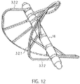
- the frame structure 3.2.1 has a circumferential, helical or spiral outer boundary frame 3.2.2 with a plurality of rotor frames 3.2.3 connected to the boundary frame 3.2.2 and extending radially inward (FIG. Fig. 12 ). At the free ends of the rotor struts 3.2.3 rings 3.2.4 are formed. Through the rings 3.2.4 of the rotor struts 3.2.3, the drive shaft 4 extends.
- a spacer sleeve 16 is arranged in each case.
- the distal end of the rotor 3.2 rests against the bearing disk 15 with a spacer sleeve 16 at the distal end.
- the end-side spacer sleeve 16 may also be formed as a special bearing spacer sleeve 16. In this way, two of the frame structures 3.2.1 form a two-bladed rotor 3.2.
- the rotor 3.2 can also be one-piece ( Fig. 11b ) or have a plurality of frame structures ( Fig. 11a ). Each frame structure forms a rotor blade.
- a frame structure 3.2.1 is shown for a rotor 3.2, which forms two rotor blades. If required, a plurality of rotor blades and, accordingly, a plurality of frame structures 3.2.1 can be arranged on a rotor 3.2.
- the frame structure may also have any other suitable shape.
- the distance between two adjacent rings 3.2.4 is smaller than the corresponding portion of the spiral bounding box 3.2.2.
- the slope of the rotor 3.2 can be determined. It can vary within a rotor 3.2.
- the pitch of the rotor 3.2 is determined.
- the length of the spacer sleeves 16 can be uniform for all positions, but it can also be varied symmetrically or asymmetrically for each position. Due to the complete design freedom, a very flexible design of the rotor 3.2 can be achieved. By The flexible design makes it possible to generate different conveying or pumping properties of the rotor 3.2.
- the rotor 3.2 has a high dimensional stability with a flexible design possibility and with minimum use of material (for example a thin frame structure). It achieves maximum rigidity and stability. Nevertheless, the combination of the frame structure with the string, which further supports the properties of the frame structure by stabilization, allows very high compression. This leads to the very good compressibility and expandability of the rotor. Due to the good surface formation of the PU skin on the lattice structure, a very good adaptation of the housing structure to the rotor structure is possible.
- the rotor 3.2 has approximately the inner diameter of the compressed pump housing 3.1 in the compressed state.
- the outer diameter of the compressed pump housing is approximately between 2 mm to 4 mm, and preferably about 3.3 mm.
- the drive shaft 4 is analogously received by a proximal connection socket 12.2.
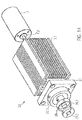
- a tubular elastic discharge hose 18 is arranged ( Fig. 1 . Fig. 13 ).
- the discharge hose 18 is formed of PU.
- the discharge hose 18 has a length of about 70 mm, a diameter of about 10 mm and a wall thickness of about 0.01 mm to 0.1 mm and preferably about 0.03 mm.
- the two ends of the outflow hose 18 are formed tapered, wherein at the proximal conical end of the outflow hose, a cylindrical portion is arranged.
- the distal conically tapered end of the outflow hose 18 closes tightly with the PU covering of the pump section 3.1.3 of the pump housing 3.1.
- the cylindrical proximal portion is fixedly connected to the proximal catheter shaft 8.2. Both are connected by means of dissolved PU liquid-tight.
- outlet openings 18.1 are arranged radially circumferentially.
- the outlet openings 18.1 may be formed oval, for example, in the conveying direction 5. It can also be provided that the outlet openings are round, half-moon-shaped or in any geometry around others Generate outlet flows.
- the outlet openings 18.1 swirl the blood emerging into the bulbus aorticus. This prevents a laminar flow and thus the water jet pump defect from the coronary arteries.
- Outflow tube 18 directs the pumping volume of the pump from the left ventricle via the aortic valve into the aorta.
- the outflow hose 18 acts as a check valve. With a positive pressure difference between outflow hose 18 and aorta, the outflow hose 18 is more or less open according to the flow rate generated by the pump. At zero or negative pressure difference, the discharge tube 18 closes due to its high flexibility just like the aortic valve and fits tightly against the proximal catheter shaft 8.2. This flexibility results in a good seal during the flow over the sails of the aortic valve. In this way, there is only low reflux from the aorta into the left ventricle.
- the clutch 9 and the motor 7 are arranged.
- the distance between the pump head 3 and the coupling 9 or the length of the proximal catheter shaft 8.2 may vary depending on the patient and is approximately 90 to 150 cm.
- a tubular cover tube 29 is arranged above the catheter device 1.
- the cover tube 29 is designed such that it surrounds the compressed pump head 3 and the proximal catheter shaft 8.2. Through the cover tube 29 of the pump head 3 is held in its compressed state.
- the cover tube 29 is withdrawn from the fixed catheter device 1 until the pump head 3 is exposed.
- Pump housing 3.1 and rotor 3.2 unfold due to the spring force of the elastic material radially outward. That is, the grid structure 3.1.6 of the pump housing 3.1 and the frame structure 3.2.1 of the rotor 3.2 expand until they have reached their predetermined diameter. It may also be provided to use temperature effects of the memory material during expansion supportive.
- the cover tube 29 is advanced to the shaft cap 10, whereby the rotor 3.2 and the pump housing 3.1 are compressed and drawn into the cover tube, after which it is extracted through the puncture site.
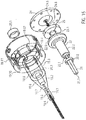
- the coupling 9 is a magnetic coupling ( Fig. 14 . Fig. 15 ).
- the clutch 9 has a clutch housing 19 with a distal magnet unit 23.1.
- the coupling housing 19 is connected to the proximal catheter shaft 8.2, which forms a continuous cavity.
- the coupling housing 19 hermetically separates the proximal catheter shaft 8.2 from a motor assembly 30.
- the motor assembly 30 has a proximal magnet unit 23.2.
- the proximal magnet unit 23.2 is non-positively connected to the motor 7.
- the distal magnet unit 23. 1 is connected to the drive shaft 4 via a coupling element 22.
- the distal magnet unit 23.1 and the proximal magnet unit 23.2 are coupled to one another in a rotationally fixed manner via magnetic forces. By the two magnet units 23.1, 23.2 a frictional connection is ensured with contact-free rotary power transmission.
- the coupling housing 19 has from distal to proximal a distal cylindrical portion 19.1, a conically widening portion 19.2, a second cylindrical portion 19.3 and a proximal cylindrical portion 19.4.
- the clutch housing is e.g. formed from polymethyl acrylate (PMMA) or another injection-moldable or machined material.
- a centrally disposed in the axial direction through hole is formed in the distal cylindrical portion 19.1 .
- the through hole extends through the entire coupling housing 19th
- the through hole narrows in three stages from a first catheter shaft receiving portion 19.5 to a second guide coil receiving portion 19.6 and to a third drive shaft passage portion 19.7.
- the bore diameter of the catheter shaft receiving portion 19.5 is about 1.9 mm, that of the guide spiral receiving portion 19.6 is about 1.28 mm and that of the third bore portion is about 1.0 mm.
- the proximal end of the proximal catheter shaft is disposed in the catheter shaft receiving portion 19.5 of the clutch housing 19 and fixedly connected thereto. In the guide spiral receiving portion 19.6, the guide coil 14 is received.
- the drive shaft 4 extends through the through-bore of the drive shaft passage portion 19.7 of the distal cylindrical portion 19.1 and the conically widening portion 19.1, 19.2.
- the drive shaft passage section 19.7 expands in the conically widening section 19.2 into a fourth bore section 19.8.
- the fourth bore section merges into a hollow cylindrical bearing section 19. 9 at the beginning of the second cylindrical section 19.
- an outer ring magnet 20.1 is arranged in the distal end region of the storage section 19.9.
- the outer ring magnet 20.1 is fixed via a press fit in the bore of the bearing section 19.9 and can additionally or alternatively be fixed by means of an adhesive bond.
- the storage section 19.9 has a diameter of about 10 mm.
- the bore of the bearing portion 19.9 is in a larger sixth distal Coupling section 19.10 over.
- a radially arranged flushing bore 19.15 is formed in the distal coupling section 19.10.
- a pump for introducing a medium, e.g. NaCl, glucose solution, Ringer's solution, plasma expander, etc. connected.
- a medium e.g. NaCl, glucose solution, Ringer's solution, plasma expander, etc. connected.
- the bore of the distal coupling portion 19.10 merges into a larger proximal coupling portion 19.11.
- 19.11 formed paragraph 19.12 8 x M 1.6 threaded holes 19.13 are radially symmetrical.
- At the proximal end of the proximal portion 19.4 three L-shaped cutouts 19.14, distributed around the circumference, arranged.
- the distal coupling portion 19.10 has a diameter of about 22 mm.
- the flushing bore 19.15 has a diameter of about 6.5 mm and the proximal coupling portion 19.11 has a diameter of about 30 mm.
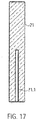
- the proximal end of the drive shaft 4 is rotatable, tensile and pressure-resistant (non-positively) connected to a cuboid square bar 21 ( Figure 17 ).
- the square rod 21 In the axial direction, the square rod 21 has a recess 21.1 for receiving the proximal end of the drive shaft 4.
- the drive shaft 4 is fixed in the recess.
- the square rod 21 is made of brass, for example, which has good lubricating properties. Other suitable materials are all materials to be extruded or cut, such as PE, PP, PTFE, gold, silver, titanium, diamond, etc.
- the square bar 21 has a length of about 19.4 mm and a cross section of about 2.88 mm x 2.88 mm.
- the square rod 21 transmits the rotational movement of the motor to the drive shaft.
- the square rod 21 may have any geometric shape that allows a statically determined force entry.
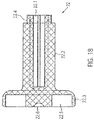
- the square rod 21 is received by an axial recess 22.1 axially displaceable within a rotationally symmetrical coupling element 22 ( Fig. 23 ). As a result, it is able to compensate for differences in length in the axial direction ( Fig. 18 ).
- the recess 22.1 is formed by a larger, central bore and four along the circumference of the central bore arranged smaller holes.
- the holes may be formed by drilling, erosion, ultrasonic drilling, laser drilling or water jet drilling.
- the arrangement of the holes four axially extending double stop edges are provided.
- the recess 22.1 is arranged within a cylindrical portion 22.2 of the coupling element 22 and extends from the distal end of the coupling element 22 to just before a disc-shaped proximal portion 22.3 of the coupling element 22nd
- the cylindrical portion 22.2 has an outer diameter of about 8 mm and the disc-shaped portion 22.3 has an outer diameter of about 18 mm.
- the recess 22.1 is formed such that the square rod 21 is fixed radially or in the circumferential direction and is received axially displaceable.
- the radial fixation of the square bar 21 is effected by the contacting of all four longitudinal edges of the square bar 21 with one of the four double stop edges of the recess 22.1. With an axial displacement of the square rod 21 in the recess 22.1 results in the corresponding lines of contact only a minimal friction.
- stop edges can also be provided more or less stop edges.
- a square bar for example, a triangular or pentagonal bar or a profile bar with an arbitrary in the longitudinal direction of the rod constant cross-sectional area can be provided.
- the recess 22.1 is to be adapted in shape corresponding to the cross-sectional area of the profile bar.
- a shoulder 22.4 is formed at the distal outer end or circumference of the cylindrical portion 22.2 of the coupling element 22 at the distal outer end or circumference of the cylindrical portion 22.2 of the coupling element 22.
- a second inner ring magnet 20.2 is arranged at the distal outer end or circumference of the cylindrical portion 22.2.
- the paragraph 22.4 takes the ring magnet 20.2 such that its outer surface is flush with the lateral surface of the cylindrical portion 22.2. This forms in conjunction with the 19.9 of the coupling housing 19 in the surrounding him corresponding outer ring magnet 20.1 a magnetic ring bearing 20.3.
- the two ring magnets 20.1, 20.2 are arranged such that e.g. the north pole of the outer ring magnet is oriented distally and the south pole is oriented proximally.
- the north and the south pole of the inner ring magnet are formed correspondingly opposite. Accordingly, the north and south poles of the two ring magnets can also be arranged vice versa.
- the magnetic ring bearing 20.3 centers the drive shaft 4 in the axial and in the radial direction. The radial centering is done by the magnetic attraction forces in the radial direction.
- the axial centering takes place in that with a small offset of the inner ring magnet 20.2 magnetic restoring forces are generated, which pull the inner ring magnet 20.2 in a position coinciding in the axial direction with the position of the outer ring magnet 20.1 position. At a larger offset, however, repulsion forces between the two magnetic rings 20.1 and 20.2 occur, whereby they are pressed apart.
- the ring magnets 20.1, 20.2 do not touch, i. no lubrication is required.
- the magnetic ring bearing dampens vibration.
- a magnet receptacle 22.5 is formed in the disk-shaped section 22.3 of the magnetic coupling element 22.
- the magnet holder 22.5 is a centric circular cutout.
- the central circular cutout 22.5 has a diameter of about 16.5 mm and a depth of about 3 mm.
- the magnet holder 22.5 accommodates the four-segment annular distal magnet unit 23.1.
- the annular distal magnet unit is glued into the magnet holder 22.5.
- a ball head bearing mount 22.6 is formed centrally.
- the ball-head bearing mount 22.6 is an approximately hemispherical recess 22.6.
- the hemispherical recess 22.6 has a diameter of about 0.5 to 1.3 mm.
- the square rod 21 or the cylindrical section of the coupling element 22 is received by the fourth bore section 19.8 or by the bearing section 19.9 of the coupling housing 19.
- the disc-shaped portion 22.3 of the coupling element 22 is received by the distal coupling portion 19.10 of the coupling housing 19.
- the clutch housing 19 is hermetically separated from the engine assembly by a shroud 24 ( Fig. 19 ).
- the clutch housing 19 is gas-tight and liquid-tight except for the flushing bore 19.15 in the clutch housing 22 and the free spaces between the drive shaft passage section 19.7 and the drive shaft 4.
- the cover plate 24 is arranged on the shoulder 19.12 of the coupling housing 19 and is fixed by eight screws, which are received in accordance with radially symmetrically arranged in the cover plate 24 holes 24.1 and are screwed into the threaded holes 19.13 of the coupling housing 19. This compound is liquid and gas tight.
- the cover plate 24 is formed for example of polymethyl acrylate (PMMA) or other non-metallic material (such as Peek, PEBAX, Teflon, PP, PE, all injection-moldable, extrudable or to be cut, non-magnetic materials).
- PMMA polymethyl acrylate
- other non-metallic material such as Peek, PEBAX, Teflon, PP, PE, all injection-moldable, extrudable or to be cut, non-magnetic materials.
- the lens 24 On the distal side, the lens 24 has a central thickening 24.2.
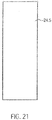
- a cylindrical centering pin 24.5 is fixed ( Figure 21 ).
- a ball head 24.6 is arranged which is received in the hemispherical cutout ( Fig. 15 . Fig. 20 ).
- the distal magnet unit 23.1 is acted upon proximally with a force. These opposite forces cause a resultant force with which the coupling element 22 is pressed against the ball head 24.6. This resulting force is adjusted so that the ball head 24.6 is stored safely and yet the wear in the ball bearing is kept low.
- the ball head 24.6 forms in conjunction with the distally disposed ball head bearing mount 22.7 of the coupling element 22 a ball head bearing 25.
- the ball bearing 25 is a sliding bearing.
- plain bearings such as e.g. a conical bearing or a cylinder head bearing possible, in which instead of the ball a cone or a cylinder is provided as a bearing body.
- the receptacle is adapted to the shape of the bearing body accordingly.
- the axial centering of the magnetic ring bearing 20.3 takes place in that the inner ring magnet 20.2 is not located in the axial direction exactly centered in the outer ring magnet 20.1, but is slightly proximal vesum. As a result, the inner ring magnet 20.2 is acted upon distally with a force.
- the ball head 24.6 may be formed of ruby, aluminum oxide or a hard plastic.
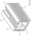
- the motor arrangement comprises the proximal magnet unit 23.2, a proximal magnet mount 26, a coupling flange 27, a motor mount 7.1, with a cooling fan arranged thereon and the motor 7 (FIG. Fig. 14 . Fig. 22 ).
- a proximal magnet unit 23.2 is arranged axially in alignment with the distal magnet unit 23.1 at a distance of approximately 0.5 to 8 mm and preferably approximately 1 to 2 mm.
- the proximal annular magnet unit 23.2 has four segments analogous to the distal magnet unit 23.1.
- the magnetic receptacle 26 is disc-shaped and has on its distal side a central circular cutout 26.1.
- the cutout 26.1 four magnetic segments by means of two-component epoxy adhesive or cyanoacrylate adhesive are glued analogously to the distal magnet unit 23.1 (see above).
- the four segments of the distal and the proximal magnet unit 23.1, 23.2 may be formed as bent bar magnets each having a different polarity at their end regions.
- the four segments may also be formed as four quarters of a bent ring magnet.
- the segments can also be designed as short, axially aligned bar magnets which are arranged in a ring. It can also be provided more than four segments. In the initial position, the two magnets are arranged such that each overlap a north and a south pole of the bar magnet of the two magnet units 23.1, 23.2 and attract each other.
- the four segments are arranged four times alternating with their north and south poles on impact so that the segments attract a magnet unit.
- the distal and the proximal magnet unit 23.1, 23.2 are arranged to one another such that complementary poles are arranged opposite each other. As a result, the two magnet units attract and it can be a torque transmitted because the magnetic forces would like to maintain this complementary pole arrangement.
- the central circular cutout 26.1 has a diameter of approximately 16.5 mm and a depth of approximately 3 mm.
- the magnet holder 26 is connected to a motor shaft 7.2 of the motor 7.
- the magnet holder 26 is rotatably disposed within a correspondingly shaped recess of the coupling flange 27 of the motor mount.
- the magnet holder 26 is rotatably disposed within a correspondingly shaped recess of the coupling flange 27 of the motor mount.
- the magnet holder 26 is rotatably disposed within a correspondingly shaped recess of the coupling flange 27 of the motor mount.
- the coupling flange 27 are arranged equally spaced three dowel pins 27.1.
- the clutch housing 19 is connected to the dowel pins 27.1 of the coupling flange 27 of the motor assembly.
- the coupling flange 27 is secured while maintaining the axis symmetry on a distal end face 7.1.1 of the motor mount.
- the motor mount 7.1 is a cuboid body, are arranged on the side surfaces 7.1.2 cooling fins 7.1.3.
- the motor mount 7.1 has a centrally located bore 7.1.4 in the axial direction. Through this hole 7.1.4, the motor shaft is guided 7.2. Furthermore, an axially aligned recess 7.1.5 is provided in which the motor 7 is arranged.
- the motor 7 is for example a standard electric motor from Faulhaber with a power of 38 W at 30,000 rpm or another suitable motor.
- a cooling fan is arranged on a side surface 7.1.2 of the cuboid motor mount 7.1 .
- a cover tube 29 is arranged over the pump head 3 and a distal portion of the proximal catheter shaft piece.
- the cover tube 29 has an inner diameter which corresponds in the region of the pump head 3 to the outer diameter of the unexpanded pump housing.
- the outer diameter of the cover tube is approximately 3 mm.
- the two magnet units 23.1, 23.2 are spatially separated from each other by the cover plate 24 in the coupling housing 19. Due to the magnetic attraction forces between the two magnet units 23.1, 23.2 there is a non-positive connection. In each case opposite poles of the two magnet units 23.1, 23.2 face each other, whereby they attract each other and a non-rotatable frictional connection is formed.
- the ball head bearing mount 22.7 of the coupling element 22 is pressed onto the ball head 24.6 of the cover plate 24 and forms the ball head bearing 25.
- the ball bearing centered the axial movement of the drive shaft. 4
- the inner ring magnet 20.1 is radially guided at a constant distance in the outer ring magnet 20.2. In this way centered and leads the magnetic ring bearing 20.3 in conjunction with the ball bearing 25, the rotationally symmetrical movement of the coupling element 22 and the drive shaft 4 to prevent shocks or unbalance.
- the motor shaft 7.2 rotates at a speed of about 20,000 rpm to 40,000 rpm, and preferably about 32,000 rpm to 35,000 rpm, which are transmitted to the drive shaft 4.
- the delivery rate of the rotor 3.2 is from about 2 l / min to 2.5 l / min at a differential pressure of 60 mm Hg.
- the resistance at the distal magnet unit 23.1 increases.
- the magnetic fields between the proximal and the distal magnet unit 23.2, 23.1 are not completely superimposed during operation, since the distal magnet unit 23.1 of the proximal magnet unit 23.2 always runs after a little. If the required torque at the distal magnet unit 23.1 now increases, the north and south poles of the magnet units 23.1, 23.2 no longer overlap but repel each other. As a result, the distal magnet unit 23.1 is pressed distally by the proximal magnet unit 23.2. The magnetic connection between the two magnet units 23.1, 23.2 is disconnected. The drive shaft 4 stops immediately.
- the amount of the transmittable torque is limited. As soon as the set torque is exceeded, the two separate Magnetic units 23.1, 23.2.
- the distal magnet unit 23.1 can no longer run after the proximal magnet unit 23.2 due to the rapid rotational movement, since the magnetic binding forces are no longer sufficient. As a result, the north and south poles no longer overlap and the magnet units 23.1, 23.2 repel each other.
- the connection of the magnet units 23.1, 23.2 is separated and limits the maximum transmissible torque.
- the magnet units 23.1, 23.2 are held by the magnetic ring bearing 20.3 by the mutual repulsion of the ring magnets 20.1, 20.2 in the decoupled state.
- This condition can be changed again by applying an external magnetic field.
- an external magnetic field By means of a magnet which is guided past the coupling housing 19 from distal to proximal, the two magnet units 23.1, 23.2 can be returned to their coupled initial position.
- the coupling housing 19 and the motor assembly 30 are spatially separated. This makes it possible to lubricate the drive shaft 4 via the arranged on the flushing bore 19.15 pump despite the high speed with in about 5-10 ml / h, so as to minimize the friction. It can also be provided to introduce an infusion via the flushing bore 19.15, which also lubricates the drive shaft 4.
- the small diameter of the drive shaft is at high speeds of about 32,000 rev / min of advantage.
- the peripheral speed would be too high and it could cause damage to the drive shaft 4 and the adjacent components due to the friction.
- the drive shaft 4 can transmit torque even with an axial length change (extension and shortening).
- a change in length occurs, for example, when the pump head 3 is compressed.
- the rotor 3.2 is compressed to the drive shaft folded and clamped in the housing.
- the pump housing 3.1 extends proximally. The drive shaft 4 can move so far that it is not torn off the rotor 3.2.
- the pump head 3 is arranged in the left ventricle in such a way that the outflow tube 18 is arranged approximately centrally in the transition of the aorta to the heart, that is to say in the region of the heart valve.
- the catheter device 1 is preferably designed such that it can be used to produce a specific pump pressure in the range from approximately 100 mm Hg to 150 mm Hg.
- the catheter device delivers blood when the pressure built up by the heart is less than the pump pressure. A sick heart is thus relieved.
- the catheter device can not deliver blood. In this case, the outflow tube is compressed by the heart valve, so that it is sealed. However, if the pressure difference is smaller than the pump pressure, then some blood is delivered against the pressure difference.
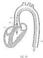
- Fig. 24 shows the positioned catheter device 1 for left heart support.
- the pump head 3 is completely in the left ventricle.
- the discharge hose extends through the heart valve.
- a cover tube 29 is first guided by means of a guide wire into the left ventricle (Seldinger technique). The Guide wire is then removed from the cover tube.
- the catheter device 1 is introduced with compressed and cooled pump housing 3.1 and rotor 3.2 through the cover tube until the catheter device 1 with the pump head 3 has reached the left ventricle. Unfolding occurs by retracting the cover tube 29 on the fixed catheter shaft 8 until the tip of the cover tube 29 has released the pumphead 3.
- the cover tube 29 is advanced to the butt plate 10, whereby rotor 3.2 and pump housing 3.1 are retracted in the compressed state in the cover tube 29, after which it is extracted through the puncture site.
- a pumping medium is provided from proximal to distal, that is to say pumping against the original conveying direction 5 ( Fig. 25 II).
- the bearing disk 15 is arranged on the proximal side of the rotor 3.2.
- the conveying direction to the distal can be realized either by reversing the direction of rotation with respect to the above embodiment or by reversing the pitch of the rotor 3.2.
- Outflow tube 18 is located at the distal end of the pump section of pump housing 19 and extends distally beyond the pump head.
- the outflow tube may have a lattice structure of a shape memory material, eg similar to that of the pump housing.
- the butt plate 10 extends beyond the distal end of the outflow tube.
- the pumping medium flows through the now serving as an inlet outlet openings of the pump housing into the pump housing and passes through the now serving as an outlet inlet opening of the pump housing in the discharge hose 18.
- the pumping medium exits from the catheter device 1 via the distal end of the discharge hose.
- the embodiment just described may be provided, for example, for use in the right ventricle.
- the catheter device according to the invention can also be designed such that pumping from distal to proximal and from proximal to distal is possible ( Fig. 25 III).
- bearing washers 15 are provided at the distal and proximal ends of the rotor 3.2.
- the outflow tube 18 is arranged at the distal end of the pump section 3.1.3 of the pump housing 3.1 and extends in the distal direction.
- the discharge hose 18 has a grid structure for stiffening, e.g. similar to the pump housing.
- the grid structure is covered with a PU skin.
- the diameter of the discharge hose corresponds approximately to that of the expanded pump housing.
- a pumping medium can enter and exit through the outlet openings of the pump housing.
- the pumping medium then enters, for example, via the outlet openings of the pump housing and the inlet openings of the pump housing in the outflow tube and exits at the distal end of the outflow tube.
- the flow through the catheter device is reversed accordingly.
- the pumping medium enters the outflow hose at the distal end of the outflow hose and passes via the inlet opening of the pump housing to the outlet openings of the pump housing.
- the embodiment just described can be used, for example, for drainage or for filling hollow organs or spaces.
- the reversal of the conveying direction can be achieved on the one hand by reversing the direction of rotation of the rotor and on the other hand by reversing the pitch of the rotor.
- the magnet units each have four curved bar magnets, each with opposite Poland are put together.
- the magnet units can also be designed such that the north and south poles of the magnet units are aligned in the axial direction, wherein the poles are arranged on the axially distally or proximally facing surfaces.
- the magnets are arranged annularly according to the previous embodiments.
- Such a coupling can be used for example for driving a milling head instead of a rotor.
- a microfiller e.g. Kidney stones or bone are minimally invasively milled.
- the number of magnets can basically be varied as desired.
- the radial compressibility of the components permits the realization of a puncture diameter which is justifiable for percutaneous implantation in Seldinger technique, due to the very small diameter of the catheter device of about 3 mm. Due to the expansion of the rotor up to a diameter of about 15 mm, it is still possible to realize very high flow rates.
- Expansible catheter pumps eg US 4,753,221
- a propeller with several stiff pump blades. These are arranged pivotally. Since the wings are stiff, they can not be made arbitrarily wide because they would give the catheter in the folded state, a too large thickness. Therefore, the delivery rate is limited.
- the rotor after the WO 99/44651 has an elastic band to connect the ends of a Nitinol spiral with a rotation axis. Due to this elastic connection, the helix is not perfectly centered. As a result, vibrations occur during pumping which make higher speeds or delivery rates impossible. Due to the frame structure of the rotor with boundary frame and rotor struts according to the catheter device 1, the rotor is more stable, foldable and can be expanded to almost any size diameter. The fact that an almost arbitrarily long training of the rotor in the longitudinal direction is possible, the radial extent of the rotor is arbitrary. Thus, any particular very high flow rates can be achieved and it is possible to customize the flow rate for each application individually.
- the pitch of the rotor can also be varied as desired.
- the rotor may be formed with one or more rotor blades, wherein the rotor blades have correspondingly a quarter, a half, a whole or any number of wraps around the drive shaft. This means that the rotor according to the invention can be varied as desired in terms of its size, its shape, its pitch and can therefore be used for a wide variety of applications.
Landscapes
- Health & Medical Sciences (AREA)
- Heart & Thoracic Surgery (AREA)
- Engineering & Computer Science (AREA)
- Life Sciences & Earth Sciences (AREA)
- General Health & Medical Sciences (AREA)
- Anesthesiology (AREA)
- Biomedical Technology (AREA)
- Hematology (AREA)
- Cardiology (AREA)
- Animal Behavior & Ethology (AREA)
- Mechanical Engineering (AREA)
- Public Health (AREA)
- Veterinary Medicine (AREA)
- Vascular Medicine (AREA)
- External Artificial Organs (AREA)
- Non-Portable Lighting Devices Or Systems Thereof (AREA)
- Endoscopes (AREA)
- Eye Examination Apparatus (AREA)
Applications Claiming Priority (3)
| Application Number | Priority Date | Filing Date | Title |
|---|---|---|---|
| EP07019658A EP2047873B1 (fr) | 2007-10-08 | 2007-10-08 | Dispositif de cathéter |
| PCT/EP2008/007015 WO2009046789A1 (fr) | 2007-10-08 | 2008-08-27 | Mécanisme de cathéter |
| EP08785716.5A EP2217300B1 (fr) | 2007-10-08 | 2008-08-27 | Mécanisme de cathéter |
Related Parent Applications (2)
| Application Number | Title | Priority Date | Filing Date |
|---|---|---|---|
| EP08785716.5A Division-Into EP2217300B1 (fr) | 2007-10-08 | 2008-08-27 | Mécanisme de cathéter |
| EP08785716.5A Division EP2217300B1 (fr) | 2007-10-08 | 2008-08-27 | Mécanisme de cathéter |
Publications (1)
| Publication Number | Publication Date |
|---|---|
| EP3427770A1 true EP3427770A1 (fr) | 2019-01-16 |
Family
ID=39049395
Family Applications (11)
| Application Number | Title | Priority Date | Filing Date |
|---|---|---|---|
| EP07019658A Active EP2047873B1 (fr) | 2007-10-08 | 2007-10-08 | Dispositif de cathéter |
| EP10008268.4A Active EP2298374B1 (fr) | 2007-10-08 | 2008-08-27 | Dispositif de cathéter |
| EP18186035.4A Pending EP3427770A1 (fr) | 2007-10-08 | 2008-08-27 | Mécanisme de cathéter |
| EP17151182.7A Pending EP3187210A1 (fr) | 2007-10-08 | 2008-08-27 | Dispositif de cathéter |
| EP08785716.5A Active EP2217300B1 (fr) | 2007-10-08 | 2008-08-27 | Mécanisme de cathéter |
| EP15002836.3A Active EP3000492B2 (fr) | 2007-10-08 | 2008-08-27 | Dispositif de catheter |
| EP10008271.8A Active EP2308524B2 (fr) | 2007-10-08 | 2008-08-27 | Dispositif de cathéter |
| EP10008272.6A Active EP2345440B1 (fr) | 2007-10-08 | 2008-08-27 | Dispositif de cathéter |
| EP10008270.0A Active EP2301598B2 (fr) | 2007-10-08 | 2008-08-27 | Dispositif de cathéter |
| EP17162607.0A Active EP3216467B1 (fr) | 2007-10-08 | 2008-08-27 | Dispositif de cathéter |
| EP15002837.1A Active EP3000493B2 (fr) | 2007-10-08 | 2008-08-27 | Dispositif de catheter |
Family Applications Before (2)
| Application Number | Title | Priority Date | Filing Date |
|---|---|---|---|
| EP07019658A Active EP2047873B1 (fr) | 2007-10-08 | 2007-10-08 | Dispositif de cathéter |
| EP10008268.4A Active EP2298374B1 (fr) | 2007-10-08 | 2008-08-27 | Dispositif de cathéter |
Family Applications After (8)
| Application Number | Title | Priority Date | Filing Date |
|---|---|---|---|
| EP17151182.7A Pending EP3187210A1 (fr) | 2007-10-08 | 2008-08-27 | Dispositif de cathéter |
| EP08785716.5A Active EP2217300B1 (fr) | 2007-10-08 | 2008-08-27 | Mécanisme de cathéter |
| EP15002836.3A Active EP3000492B2 (fr) | 2007-10-08 | 2008-08-27 | Dispositif de catheter |
| EP10008271.8A Active EP2308524B2 (fr) | 2007-10-08 | 2008-08-27 | Dispositif de cathéter |
| EP10008272.6A Active EP2345440B1 (fr) | 2007-10-08 | 2008-08-27 | Dispositif de cathéter |
| EP10008270.0A Active EP2301598B2 (fr) | 2007-10-08 | 2008-08-27 | Dispositif de cathéter |
| EP17162607.0A Active EP3216467B1 (fr) | 2007-10-08 | 2008-08-27 | Dispositif de cathéter |
| EP15002837.1A Active EP3000493B2 (fr) | 2007-10-08 | 2008-08-27 | Dispositif de catheter |
Country Status (7)
| Country | Link |
|---|---|
| EP (11) | EP2047873B1 (fr) |
| CN (2) | CN102805885B (fr) |
| AT (1) | ATE491483T1 (fr) |
| CA (5) | CA3020250C (fr) |
| DE (6) | DE502007005973D1 (fr) |
| ES (1) | ES2901005T3 (fr) |
| WO (1) | WO2009046789A1 (fr) |
Families Citing this family (137)
| Publication number | Priority date | Publication date | Assignee | Title |
|---|---|---|---|---|
| US7393181B2 (en) | 2004-09-17 | 2008-07-01 | The Penn State Research Foundation | Expandable impeller pump |
| AU2007230945B2 (en) | 2006-03-23 | 2013-05-02 | The Penn State Research Foundation | Heart assist device with expandable impeller pump |
| EP2047873B1 (fr) * | 2007-10-08 | 2010-12-15 | Ais Gmbh Aachen Innovative Solutions | Dispositif de cathéter |
| US8439859B2 (en) | 2007-10-08 | 2013-05-14 | Ais Gmbh Aachen Innovative Solutions | Catheter device |
| US8489190B2 (en) | 2007-10-08 | 2013-07-16 | Ais Gmbh Aachen Innovative Solutions | Catheter device |
| EP2194278A1 (fr) | 2008-12-05 | 2010-06-09 | ECP Entwicklungsgesellschaft mbH | Pompe à fluide dotée d'un rotor |
| EP2216059A1 (fr) | 2009-02-04 | 2010-08-11 | ECP Entwicklungsgesellschaft mbH | Dispositif de cathéter doté d'un cathéter et d'un dispositif d'actionnement |
| EP2229965A1 (fr) | 2009-03-18 | 2010-09-22 | ECP Entwicklungsgesellschaft mbH | Pompe à fluide dotée d'une forme spéciale de lame de rotor |
| EP2246078A1 (fr) | 2009-04-29 | 2010-11-03 | ECP Entwicklungsgesellschaft mbH | Agencement d'arbres doté d'un arbre se déroulant à l'intérieur d'une enveloppe rempli de fluide |
| EP2248544A1 (fr) | 2009-05-05 | 2010-11-10 | ECP Entwicklungsgesellschaft mbH | Pompe à fluide à diamètre modifiable, notamment à des fins médicales |
| EP2266640A1 (fr) | 2009-06-25 | 2010-12-29 | ECP Entwicklungsgesellschaft mbH | Pale comprimable et extensible pour une pompe à fluide |
| EP2448613B1 (fr) * | 2009-07-01 | 2019-11-06 | The Penn State Research Foundation | Pompe pour le sang pourvue d'une canule extensible |
| EP2282070B1 (fr) | 2009-08-06 | 2012-10-17 | ECP Entwicklungsgesellschaft mbH | Dispositif de cathéter doté d'un dispositif d'accouplement pour un dispositif d'entraînement |
| EP2298373A1 (fr) | 2009-09-22 | 2011-03-23 | ECP Entwicklungsgesellschaft mbH | Pompe à fluide dotée d'au moins une aube directrice et d'un dispositif d'appui |
| EP4215752A1 (fr) | 2009-09-22 | 2023-07-26 | ECP Entwicklungsgesellschaft mbH | Rotor pouvant être comprimé pour une pompe à fluide |
| EP2298371A1 (fr) | 2009-09-22 | 2011-03-23 | ECP Entwicklungsgesellschaft mbH | Elément fonctionnel, notamment pompe à fluide, doté d'un boîtier et d'un élément de transport |
| EP2298372A1 (fr) | 2009-09-22 | 2011-03-23 | ECP Entwicklungsgesellschaft mbH | Rotor pour une pompe axiale pour le transport d'un fluide |
| EP2314331B1 (fr) | 2009-10-23 | 2013-12-11 | ECP Entwicklungsgesellschaft mbH | Agencement de pompes de cathéter et agencement d'arbres flexible doté d'une âme |
| EP2314330A1 (fr) | 2009-10-23 | 2011-04-27 | ECP Entwicklungsgesellschaft mbH | Agencement d'arbres flexible |
| US8690749B1 (en) | 2009-11-02 | 2014-04-08 | Anthony Nunez | Wireless compressible heart pump |
| EP2338540A1 (fr) | 2009-12-23 | 2011-06-29 | ECP Entwicklungsgesellschaft mbH | Palette de transport pour un rotor pouvant être comprimé |
| EP2338541A1 (fr) | 2009-12-23 | 2011-06-29 | ECP Entwicklungsgesellschaft mbH | Rotor radial pouvant être comprimé et extensible pour une pompe à fluide |
| EP2338539A1 (fr) | 2009-12-23 | 2011-06-29 | ECP Entwicklungsgesellschaft mbH | Dispositif de pompage doté d'un dispositif de détection |
| EP2347778A1 (fr) | 2010-01-25 | 2011-07-27 | ECP Entwicklungsgesellschaft mbH | Pompe à fluide dotée d'un rotor radial comprimable |
| EP2363157A1 (fr) | 2010-03-05 | 2011-09-07 | ECP Entwicklungsgesellschaft mbH | Dispositif destiné à l'action mécanique sur un milieu, notamment pompe à fluide |
| EP2388029A1 (fr) | 2010-05-17 | 2011-11-23 | ECP Entwicklungsgesellschaft mbH | Agencement de pompe |
| EP2399639A1 (fr) | 2010-06-25 | 2011-12-28 | ECP Entwicklungsgesellschaft mbH | Système d'introduction d'une pompe |
| EP2407186A1 (fr) * | 2010-07-15 | 2012-01-18 | ECP Entwicklungsgesellschaft mbH | Rotor pour une pompe, fabriquée à l'aide d'une matière première élastique |
| EP2407187A3 (fr) | 2010-07-15 | 2012-06-20 | ECP Entwicklungsgesellschaft mbH | Pompe sanguine pour l'application invasive à l'intérieur d'un corps de patient |
| EP2407185A1 (fr) | 2010-07-15 | 2012-01-18 | ECP Entwicklungsgesellschaft mbH | Rotor pouvant être comprimé et étendu radialement pour une pompe dotée d'une aube directrice |
| EP2422735A1 (fr) | 2010-08-27 | 2012-02-29 | ECP Entwicklungsgesellschaft mbH | Dispositif de transport de sang implantable, dispositif de manipulation et dispositif de couplage |
| WO2012094641A2 (fr) | 2011-01-06 | 2012-07-12 | Thoratec Corporation | Pompe cardiaque percutanée |
| EP2497521A1 (fr) | 2011-03-10 | 2012-09-12 | ECP Entwicklungsgesellschaft mbH | Dispositif de poussée pour l'introduction axiale d'un corps flexible en forme de tronçon |
| US9162017B2 (en) | 2011-08-29 | 2015-10-20 | Minnetronix, Inc. | Expandable vascular pump |
| EP2564771A1 (fr) | 2011-09-05 | 2013-03-06 | ECP Entwicklungsgesellschaft mbH | Produit médical doté d'un élément de fonction pour la mise en place invasive dans le corps d'un patient |
| US8926492B2 (en) | 2011-10-11 | 2015-01-06 | Ecp Entwicklungsgesellschaft Mbh | Housing for a functional element |
| US8721517B2 (en) | 2012-05-14 | 2014-05-13 | Thoratec Corporation | Impeller for catheter pump |
| US9872947B2 (en) | 2012-05-14 | 2018-01-23 | Tc1 Llc | Sheath system for catheter pump |
| US9446179B2 (en) | 2012-05-14 | 2016-09-20 | Thoratec Corporation | Distal bearing support |
| US9327067B2 (en) | 2012-05-14 | 2016-05-03 | Thoratec Corporation | Impeller for catheter pump |
| GB2504176A (en) | 2012-05-14 | 2014-01-22 | Thoratec Corp | Collapsible impeller for catheter pump |
| GB2504177B (en) | 2012-05-14 | 2014-12-10 | Thoratec Corp | Sheath system for catheter pump |
| CN108742951B (zh) | 2012-06-06 | 2021-05-25 | 洋红医疗有限公司 | 人工肾脏瓣膜 |
| EP4186557A1 (fr) | 2012-07-03 | 2023-05-31 | Tc1 Llc | Ensemble motour pour pompe à cathéter |
| US9358329B2 (en) | 2012-07-03 | 2016-06-07 | Thoratec Corporation | Catheter pump |
| US9421311B2 (en) | 2012-07-03 | 2016-08-23 | Thoratec Corporation | Motor assembly for catheter pump |
| CN113616920B (zh) | 2013-03-13 | 2024-10-25 | 马真塔医药有限公司 | 血液泵浦装置及制造血液泵浦的方法 |
| WO2014164136A1 (fr) | 2013-03-13 | 2014-10-09 | Thoratec Corporation | Système de traitement de fluide |
| US11077294B2 (en) | 2013-03-13 | 2021-08-03 | Tc1 Llc | Sheath assembly for catheter pump |
| US10583231B2 (en) | 2013-03-13 | 2020-03-10 | Magenta Medical Ltd. | Blood pump |
| US11033728B2 (en) | 2013-03-13 | 2021-06-15 | Tc1 Llc | Fluid handling system |
| EP2968742B1 (fr) | 2013-03-15 | 2020-12-02 | Tc1 Llc | Ensemble pompe de cathéter comprenant un stator |
| US9308302B2 (en) | 2013-03-15 | 2016-04-12 | Thoratec Corporation | Catheter pump assembly including a stator |
| JP5896478B2 (ja) * | 2013-09-24 | 2016-03-30 | 朝日インテック株式会社 | バルーンカテーテル |
| EP2860849B1 (fr) | 2013-10-11 | 2016-09-14 | ECP Entwicklungsgesellschaft mbH | Moteur comprimable, agencement d'implantation et procédé de positionnement du moteur |
| CN104721943A (zh) * | 2013-12-24 | 2015-06-24 | 微创心脉医疗科技(上海)有限公司 | 球囊、球囊扩张导管和球囊的制作方法及模具 |
| US9616159B2 (en) * | 2014-03-05 | 2017-04-11 | Medtronic Vascular Galway | Modular implantable ventricular assist device |
| US10583232B2 (en) | 2014-04-15 | 2020-03-10 | Tc1 Llc | Catheter pump with off-set motor position |
| WO2015160943A1 (fr) | 2014-04-15 | 2015-10-22 | Thoratec Corporation | Capteurs pour pompes de cathéter |
| WO2015160979A1 (fr) | 2014-04-15 | 2015-10-22 | Thoratec Corporation | Pompe de cathéter ayant des orifices d'accès |
| US10363349B2 (en) | 2014-04-15 | 2019-07-30 | Tc1 Llp | Heart pump providing adjustable outflow |
| EP4417244A3 (fr) | 2014-04-15 | 2024-10-16 | Tc1 Llc | Système d'introduction de pompe de cathéter |
| WO2016028644A1 (fr) | 2014-08-18 | 2016-02-25 | Thoratec Corporation | Eléments de guidage pour une pompe de cathéter percutané |
| CN104225696B (zh) * | 2014-09-04 | 2017-06-27 | 江苏大学 | 一种折叠式微创植入的心室内轴流血泵 |
| WO2016118784A1 (fr) | 2015-01-22 | 2016-07-28 | Thoratec Corporation | Mécanismes de fixation pour moteur de pompe pour cathéter |
| WO2016118781A2 (fr) | 2015-01-22 | 2016-07-28 | Thoratec Corporation | Ensemble moteur avec échangeur de chaleur pour pompe de cathéter |
| WO2016118777A1 (fr) | 2015-01-22 | 2016-07-28 | Thoratec Corporation | Ensemble moteur à masse de rotation réduite pour pompe pour cathéter |
| US9907890B2 (en) | 2015-04-16 | 2018-03-06 | Tc1 Llc | Catheter pump with positioning brace |
| WO2016185473A1 (fr) | 2015-05-18 | 2016-11-24 | Magenta Medical Ltd. | Pompe à sang |
| EP3153190A1 (fr) * | 2015-10-09 | 2017-04-12 | ECP Entwicklungsgesellschaft mbH | Pompe, notamment pompe a sang |
| EP3808401A1 (fr) | 2016-07-21 | 2021-04-21 | Tc1 Llc | Chambre remplie de gaz pour ensemble moteur de pompe de cathéter |
| EP3808403A1 (fr) | 2016-07-21 | 2021-04-21 | Tc1 Llc | Joints fluidiques pour ensemble moteur de pompe à cathéter |
| EP3556409B1 (fr) | 2016-10-25 | 2022-01-05 | Magenta Medical Ltd. | Dispositif d'assistance ventriculaire |
| CA3039302C (fr) | 2016-11-23 | 2025-05-13 | Magenta Medical Ltd. | Pompes à sang |
| EP4732889A2 (fr) | 2017-06-07 | 2026-04-29 | Supira Medical, Inc. | Dispositifs de déplacement de fluide intravasculaire, systèmes et procédés d'utilisation |
| EP3446731A1 (fr) * | 2017-08-23 | 2019-02-27 | ECP Entwicklungsgesellschaft mbH | Dispositif de compression d'une partie compressible dune pompe à? cathé?ter |
| EP3446730B1 (fr) | 2017-08-23 | 2021-10-06 | ECP Entwicklungsgesellschaft mbH | Couvercle d'arbre d'entraînement ayant une partie conductrice de chaleur |
| US11511103B2 (en) | 2017-11-13 | 2022-11-29 | Shifamed Holdings, Llc | Intravascular fluid movement devices, systems, and methods of use |
| CN115025386B (zh) | 2018-01-10 | 2025-07-25 | 马真塔医药有限公司 | 心室辅助装置 |
| DE102018201030B4 (de) | 2018-01-24 | 2025-10-16 | Kardion Gmbh | Magnetkuppelelement mit magnetischer Lagerungsfunktion |
| JP7410034B2 (ja) | 2018-02-01 | 2024-01-09 | シファメド・ホールディングス・エルエルシー | 血管内血液ポンプならびに使用および製造の方法 |
| US20190321601A1 (en) * | 2018-03-30 | 2019-10-24 | Jaywant P. Parmar | Electromagnetic Motion and Tracking Seldinger Technique Access System: Introducing the EMMT STA System |
| DE102018207575A1 (de) | 2018-05-16 | 2019-11-21 | Kardion Gmbh | Magnetische Stirndreh-Kupplung zur Übertragung von Drehmomenten |
| DE102018207594A1 (de) | 2018-05-16 | 2019-11-21 | Kardion Gmbh | Rotor, Magnetkupplungsvorrichtung, Elektromotor für ein Herzunterstützungssystem, Pumpeneinheit für ein Herzunterstützungssystem sowie Verfahren zum Herstellen eines Rotors |
| DE102018207611A1 (de) | 2018-05-16 | 2019-11-21 | Kardion Gmbh | Rotorlagerungssystem |
| DE102018208564A1 (de) | 2018-05-30 | 2019-12-05 | Kardion Gmbh | Steuerbare Einführungshülse |
| DE102018208537A1 (de) | 2018-05-30 | 2019-12-05 | Kardion Gmbh | Vorrichtung zum Anbinden eines Herzunterstützungssystems an eine Einführeinrichtung und Verfahren zum Herstellen einer Vorrichtung zum Anbinden eines Herzunterstützungssystems an eine Einführeinrichtung |
| DE102018208555A1 (de) | 2018-05-30 | 2019-12-05 | Kardion Gmbh | Vorrichtung zum Verankern eines Herzunterstützungssystems in einem Blutgefäß, Verfahren zum Betreiben und Herstellverfahren zum Herstellen einer Vorrichtung und Herzunterstützungssystem |
| DE102018208538A1 (de) | 2018-05-30 | 2019-12-05 | Kardion Gmbh | Intravasale Blutpumpe und Verfahren zur Herstellung von elektrischen Leiterbahnen |
| DE102018208550A1 (de) | 2018-05-30 | 2019-12-05 | Kardion Gmbh | Leitungsvorrichtung zum Leiten eines Blutstroms für ein Herzunterstützungssystem, Herzunterstützungssystem und Verfahren zum Herstellen einer Leitungsvorrichtung |
| DE102018208549A1 (de) | 2018-05-30 | 2019-12-05 | Kardion Gmbh | Elektronikmodul für ein Herzunterstützungssystem und Verfahren zum Herstellen eines Elektronikmoduls für ein Herzunterstützungssystem |
| DE102018208539A1 (de) | 2018-05-30 | 2019-12-05 | Kardion Gmbh | Motorgehäusemodul zum Abdichten eines Motorraums eines Motors eines Herzunterstützungssystems und Herzunterstützungssystem und Verfahren zum Montieren eines Herzunterstützungssystems |
| DE102018208541A1 (de) | 2018-05-30 | 2019-12-05 | Kardion Gmbh | Axialpumpe für ein Herzunterstützungssystem und Verfahren zum Herstellen einer Axialpumpe für ein Herzunterstützungssystem |
| DE102018210076A1 (de) | 2018-06-21 | 2019-12-24 | Kardion Gmbh | Verfahren und Vorrichtung zum Erkennen eines Verschleißzustands eines Herzunterstützungssystems, Verfahren und Vorrichtung zum Betreiben eines Herzunterstützungssystems und Herzunterstützungssystem |
| DE102018210058A1 (de) | 2018-06-21 | 2019-12-24 | Kardion Gmbh | Statorschaufelvorrichtung zur Strömungsführung eines aus einer Austrittsöffnung eines Herzunterstützungssystems ausströmenden Fluids, Herzunterstützungssystem mit Statorschaufelvorrichtung, Verfahren zum Betreiben einer Statorschaufelvorrichtung und Herstellverfahren |
| DE102018211297A1 (de) | 2018-07-09 | 2020-01-09 | Kardion Gmbh | Herzunterstützungssystem und Verfahren zur Überwachung der Integrität einer Haltestruktur eines Herzunterstützungssystems |
| DE102018211327A1 (de) | 2018-07-10 | 2020-01-16 | Kardion Gmbh | Laufrad für ein implantierbares, vaskuläres Unterstützungssystem |
| DE102018211328A1 (de) | 2018-07-10 | 2020-01-16 | Kardion Gmbh | Laufradgehäuse für ein implantierbares, vaskuläres Unterstützungssystem |
| DE102018212153A1 (de) | 2018-07-20 | 2020-01-23 | Kardion Gmbh | Zulaufleitung für eine Pumpeneinheit eines Herzunterstützungssystems, Herzunterstützungssystem und Verfahren zum Herstellen einer Zulaufleitung für eine Pumpeneinheit eines Herzunterstützungssystems |
| WO2020028537A1 (fr) | 2018-07-31 | 2020-02-06 | Shifamed Holdings, Llc | Pompes sanguines intravasculaires et procédés d'utilisation |
| AU2019320533B2 (en) | 2018-08-07 | 2024-11-21 | Kardion Gmbh | Bearing device for a cardiac support system, and method for flushing an intermediate space in a bearing device for a cardiac support system |
| WO2020073047A1 (fr) | 2018-10-05 | 2020-04-09 | Shifamed Holdings, Llc | Pompes à sang intravasculaires et procédés d'utilisation |
| CN111166948A (zh) * | 2018-11-09 | 2020-05-19 | 上海微创医疗器械(集团)有限公司 | 经皮血泵及其网篮 |
| CN111202877B (zh) * | 2018-11-22 | 2022-04-01 | 上海微创心力医疗科技有限公司 | 经皮血泵及其灌注系统 |
| CN111384796A (zh) * | 2018-12-29 | 2020-07-07 | 上海微创心力医疗科技有限公司 | 电机定子及制造电机定子的模具和方法以及电机与导管泵 |
| EP4653041A3 (fr) * | 2019-01-24 | 2026-03-04 | Magenta Medical Ltd. | Dispositif d'assistance ventriculaire |
| EP3698820A1 (fr) * | 2019-02-22 | 2020-08-26 | ECP Entwicklungsgesellschaft mbH | Dispositif de cathéter avec un couvercle d'arbre d'entraînement |
| US12128228B2 (en) | 2019-05-23 | 2024-10-29 | Magenta Medical Ltd | Blood pumps |
| WO2021011473A1 (fr) | 2019-07-12 | 2021-01-21 | Shifamed Holdings, Llc | Pompes à sang intravasculaires et méthode d'utilisation et procédé de fabrication |
| US11654275B2 (en) | 2019-07-22 | 2023-05-23 | Shifamed Holdings, Llc | Intravascular blood pumps with struts and methods of use and manufacture |
| EP4010046A4 (fr) | 2019-08-07 | 2023-08-30 | Calomeni, Michael | Pompes sanguines à cathéter et boîtiers de pompe pliants |
| US11730946B2 (en) | 2019-08-12 | 2023-08-22 | Boston Scientific Scimed, Inc. | Flow enhancement for circulatory support device |
| US12171994B2 (en) | 2019-09-11 | 2024-12-24 | Boston Scientific Scimed, Inc. | Reduced thrombosis blood pump with washout bearing |
| EP4034192B1 (fr) | 2019-09-25 | 2025-12-24 | Supira Medical, Inc. | Dispositifs et systèmes de pompes à sang intravasculaires et leurs procédés d'utilisation et de commande |
| WO2021062260A1 (fr) | 2019-09-25 | 2021-04-01 | Shifamed Holdings, Llc | Pompes à sang de cathéter et conduits sanguins pliables |
| EP4034221B1 (fr) | 2019-09-25 | 2024-11-13 | Shifamed Holdings, LLC | Pompes à sang de cathéter et boîtiers de pompe pliables |
| EP4072650A4 (fr) | 2019-12-11 | 2024-01-10 | Shifamed Holdings, LLC | Pompes à sang d'aorte descendante et de veine cave |
| US12599758B2 (en) | 2019-12-19 | 2026-04-14 | Shifamed Holdings, Llc | Intravascular blood pumps, motors, and fluid control |
| EP3858397A1 (fr) | 2020-01-31 | 2021-08-04 | Abiomed Europe GmbH | Pompe à sang intravasculaire |
| DE102020102474A1 (de) | 2020-01-31 | 2021-08-05 | Kardion Gmbh | Pumpe zum Fördern eines Fluids und Verfahren zum Herstellen einer Pumpe |
| DE102020102473A1 (de) | 2020-01-31 | 2021-08-05 | Kardion Gmbh | Pumpe zum Fördern eines Fluids und Verfahren zum Herstellen einer Pumpe |
| CN114746142B (zh) | 2020-04-07 | 2026-01-02 | 马真塔医药有限公司 | 心室辅助装置 |
| WO2021243263A1 (fr) | 2020-05-29 | 2021-12-02 | Shifamed Holdings, Llc | Pompes à sang intravasculaires |
| CA3192451A1 (fr) | 2020-09-14 | 2022-03-17 | Johannes Bette | Pompe de support cardiovasculaire dotee d'un impulseur a zone d'ecoulement variable |
| JP2023550938A (ja) | 2020-11-20 | 2023-12-06 | カルディオン ゲーエムベーハー | ガイドワイヤ補助具付き機械的循環支持システム |
| CN114642827B (zh) * | 2020-12-17 | 2026-03-03 | 苏州心岭迈德医疗科技有限公司 | 心室辅助泵血器械及系统 |
| CN117157122A (zh) | 2021-02-10 | 2023-12-01 | 波士顿科学国际有限公司 | 用于血液动力学支持泵的磁性推进器和轴承 |
| CN116549833B (zh) | 2021-03-09 | 2025-08-29 | 马真塔医药有限公司 | 心室辅助装置 |
| WO2022221512A1 (fr) | 2021-04-14 | 2022-10-20 | Boston Scientific Scimed Inc. | Pointe flexible pour dispositif de support circulatoire transvalvulaire |
| WO2023043973A1 (fr) * | 2021-09-17 | 2023-03-23 | Abiomed, Inc. | Pompe à sang intravasculaire |
| CN118215524A (zh) | 2021-11-16 | 2024-06-18 | 波士顿科学国际有限公司 | 有利于减少溶血的经皮循环支持系统 |
| AU2022389899B2 (en) | 2021-11-16 | 2025-02-06 | Boston Scientific Scimed Inc. | Percutaneous circulatory support device including proximal pressure sensor |
| JP7693114B2 (ja) | 2021-11-17 | 2025-06-16 | ボストン サイエンティフィック サイムド,インコーポレイテッド | 損傷なくガイドワイヤを並進することを容易にするためのデバイスハウジング形態 |
| US12133976B2 (en) | 2021-11-23 | 2024-11-05 | Boston Scientific Scimed, Inc. | Percutaneous circulatory support device facilitating reduced hemolysis class |
| EP4429754B1 (fr) | 2022-09-14 | 2025-02-12 | Magenta Medical Ltd. | Partie tête de pompe d'un dispositif d'assistance ventriculaire |
| KR20260021600A (ko) * | 2023-04-13 | 2026-02-13 | 아비오메드 유럽 게엠베하 | 혈액 펌프 |
| CN119158163B (zh) * | 2023-06-19 | 2026-04-03 | 上海心恒睿医疗科技有限公司 | 经皮心室辅助装置 |
Citations (9)
| Publication number | Priority date | Publication date | Assignee | Title |
|---|---|---|---|---|
| US4753221A (en) | 1986-10-22 | 1988-06-28 | Intravascular Surgical Instruments, Inc. | Blood pumping catheter and method of use |
| EP0364293A2 (fr) | 1988-10-13 | 1990-04-18 | Kensey Nash Corporation | Cathéter pouvant pomper du sang |
| EP0445782A1 (fr) | 1990-03-08 | 1991-09-11 | Sun Medical Technology Research Corporation | Coeur artificiel auxiliaire implanté in-vivo |
| US5112292A (en) * | 1989-01-09 | 1992-05-12 | American Biomed, Inc. | Helifoil pump |
| WO1999044651A1 (fr) | 1998-03-07 | 1999-09-10 | Guenther Rolf W | Pompe axiale autodeployable inserable par voie intravasculaire pour assistance cardiaque temporaire |
| DE10059714C1 (de) | 2000-12-01 | 2002-05-08 | Impella Cardiotech Ag | Intravasale Pumpe |
| US6454775B1 (en) * | 1999-12-06 | 2002-09-24 | Bacchus Vascular Inc. | Systems and methods for clot disruption and retrieval |
| WO2003103745A2 (fr) * | 2002-06-11 | 2003-12-18 | Walid Aboul-Hosn | Pompe a sang expansible et procedes s'y rapportant |
| JP4126158B2 (ja) | 1998-09-21 | 2008-07-30 | エムゲー・テヒノロギーズ・アクチエンゲゼルシャフト | ポリメタクリル酸メチルの解重合方法 |
Family Cites Families (36)
| Publication number | Priority date | Publication date | Assignee | Title |
|---|---|---|---|---|
| US4686982A (en) | 1985-06-19 | 1987-08-18 | John Nash | Spiral wire bearing for rotating wire drive catheter |
| US4811743A (en) | 1987-04-21 | 1989-03-14 | Cordis Corporation | Catheter guidewire |
| US5154705A (en) * | 1987-09-30 | 1992-10-13 | Lake Region Manufacturing Co., Inc. | Hollow lumen cable apparatus |
| US4846152A (en) | 1987-11-24 | 1989-07-11 | Nimbus Medical, Inc. | Single-stage axial flow blood pump |
| US5300112A (en) | 1992-07-14 | 1994-04-05 | Aai Corporation | Articulated heart pump |
| SE501215C2 (sv) | 1992-09-02 | 1994-12-12 | Oeyvind Reitan | Kateterpump |
| US5376114A (en) | 1992-10-30 | 1994-12-27 | Jarvik; Robert | Cannula pumps for temporary cardiac support and methods of their application and use |
| US5735792A (en) | 1992-11-25 | 1998-04-07 | Clarus Medical Systems, Inc. | Surgical instrument including viewing optics and an atraumatic probe |
| US5957672A (en) | 1993-11-10 | 1999-09-28 | The United States Of America As Represented By The Administrator Of The National Aeronautics And Space Administration | Blood pump bearing system |
| US5947892A (en) | 1993-11-10 | 1999-09-07 | Micromed Technology, Inc. | Rotary blood pump |
| US5527159A (en) | 1993-11-10 | 1996-06-18 | The United States Of America As Represented By The Administrator Of The National Aeronautics And Space Administration | Rotary blood pump |
| US5746692A (en) | 1994-05-05 | 1998-05-05 | Imagen Medical, Inc. | Catheter and endoscope system with distal protruding ball tip and method |
| US6436056B1 (en) | 1996-02-28 | 2002-08-20 | Boston Scientific Corporation | Polymeric implements for torque transmission |
| US6254359B1 (en) | 1996-05-10 | 2001-07-03 | The United States Of America As Represented By The Administrator Of The National Aeronautics And Space Administration | Method for providing a jewel bearing for supporting a pump rotor shaft |
| DE19622335C2 (de) * | 1996-06-04 | 1999-03-18 | Voelker Wolfram Priv Doz Dr Me | Ballonkatheter |
| US5776079A (en) | 1996-08-06 | 1998-07-07 | Cook Incorporated | Retrograde-antegrade catheterization guide wire |
| DE19821307C1 (de) * | 1998-05-13 | 1999-10-21 | Impella Cardiotech Gmbh | Intrakardiale Blutpumpe |
| US6245007B1 (en) | 1999-01-28 | 2001-06-12 | Terumo Cardiovascular Systems Corporation | Blood pump |
| EP1034808A1 (fr) * | 1999-03-09 | 2000-09-13 | Paul Frederik Gründeman | Dispositif mécanique transventriculaire d'aide circulatoire |
| WO2001017581A2 (fr) | 1999-09-03 | 2001-03-15 | A-Med Systems, Inc. | Pompe a sang intravasculaire pouvant etre guidee et procedes s"y rapportant |
| US6585758B1 (en) | 1999-11-16 | 2003-07-01 | Scimed Life Systems, Inc. | Multi-section filamentary endoluminal stent |
| US20010031981A1 (en) * | 2000-03-31 | 2001-10-18 | Evans Michael A. | Method and device for locating guidewire and treating chronic total occlusions |
| US6855136B2 (en) | 2002-04-03 | 2005-02-15 | Gore Enterprise Holdings, Inc. | Infusion catheter having an atraumatic tip |
| US7678068B2 (en) | 2002-12-02 | 2010-03-16 | Gi Dynamics, Inc. | Atraumatic delivery devices |
| WO2005009286A2 (fr) | 2003-07-23 | 2005-02-03 | Viacor, Inc. | Procede et appareil permettant d'ameliorer la fonction de la valvule mitrale |
| WO2005030296A2 (fr) | 2003-09-25 | 2005-04-07 | Medforte Research Foundation | Pompe sanguine a debit axial presentant un impulseur stabilise radialement et axialement, magnetiquement suspendu |
| US7763011B2 (en) | 2003-12-22 | 2010-07-27 | Boston Scientific Scimed, Inc. | Variable density braid stent |
| AU2005272610B2 (en) * | 2004-08-13 | 2011-10-20 | Procyrion, Inc. | Method and apparatus for long-term assisting a left ventricle to pump blood |
| US7393181B2 (en) | 2004-09-17 | 2008-07-01 | The Penn State Research Foundation | Expandable impeller pump |
| DE102004054714A1 (de) | 2004-11-12 | 2006-05-24 | Impella Cardiosystems Gmbh | Faltbare intravasal einführbare Blutpumpe |
| US20090069854A1 (en) | 2005-04-21 | 2009-03-12 | Eqlibra Medical Ltd. | Implantable electric device |
| AU2007230945B2 (en) | 2006-03-23 | 2013-05-02 | The Penn State Research Foundation | Heart assist device with expandable impeller pump |
| DE502007005015C5 (de) * | 2007-10-08 | 2020-02-20 | Ais Gmbh Aachen Innovative Solutions | Katheter-Vorrichtung |
| EP2047873B1 (fr) * | 2007-10-08 | 2010-12-15 | Ais Gmbh Aachen Innovative Solutions | Dispositif de cathéter |
| US8489190B2 (en) * | 2007-10-08 | 2013-07-16 | Ais Gmbh Aachen Innovative Solutions | Catheter device |
| EP2229965A1 (fr) * | 2009-03-18 | 2010-09-22 | ECP Entwicklungsgesellschaft mbH | Pompe à fluide dotée d'une forme spéciale de lame de rotor |
-
2007
- 2007-10-08 EP EP07019658A patent/EP2047873B1/fr active Active
- 2007-10-08 DE DE502007005973T patent/DE502007005973D1/de active Active
- 2007-10-08 AT AT07019658T patent/ATE491483T1/de active
-
2008
- 2008-08-27 DE DE202008018622.6U patent/DE202008018622U1/de not_active Expired - Lifetime
- 2008-08-27 EP EP10008268.4A patent/EP2298374B1/fr active Active
- 2008-08-27 CN CN201210246027.XA patent/CN102805885B/zh active Active
- 2008-08-27 DE DE202008018612.9U patent/DE202008018612U1/de not_active Expired - Lifetime
- 2008-08-27 EP EP18186035.4A patent/EP3427770A1/fr active Pending
- 2008-08-27 EP EP17151182.7A patent/EP3187210A1/fr active Pending
- 2008-08-27 CA CA3020250A patent/CA3020250C/fr active Active
- 2008-08-27 CA CA2701809A patent/CA2701809C/fr active Active
- 2008-08-27 EP EP08785716.5A patent/EP2217300B1/fr active Active
- 2008-08-27 EP EP15002836.3A patent/EP3000492B2/fr active Active
- 2008-08-27 ES ES17162607T patent/ES2901005T3/es active Active
- 2008-08-27 EP EP10008271.8A patent/EP2308524B2/fr active Active
- 2008-08-27 EP EP10008272.6A patent/EP2345440B1/fr active Active
- 2008-08-27 WO PCT/EP2008/007015 patent/WO2009046789A1/fr not_active Ceased
- 2008-08-27 EP EP10008270.0A patent/EP2301598B2/fr active Active
- 2008-08-27 CN CN2008801107193A patent/CN101854964B/zh active Active
- 2008-08-27 EP EP17162607.0A patent/EP3216467B1/fr active Active
- 2008-08-27 DE DE202008018576.9U patent/DE202008018576U1/de not_active Expired - Lifetime
- 2008-08-27 EP EP15002837.1A patent/EP3000493B2/fr active Active
- 2008-08-27 DE DE202008018575.0U patent/DE202008018575U1/de not_active Expired - Lifetime
- 2008-08-27 DE DE202008018578.5U patent/DE202008018578U1/de not_active Expired - Lifetime
- 2008-08-27 CA CA3020247A patent/CA3020247C/fr active Active
- 2008-08-27 CA CA3020253A patent/CA3020253C/fr active Active
- 2008-08-27 CA CA3178216A patent/CA3178216A1/fr active Pending
Patent Citations (9)
| Publication number | Priority date | Publication date | Assignee | Title |
|---|---|---|---|---|
| US4753221A (en) | 1986-10-22 | 1988-06-28 | Intravascular Surgical Instruments, Inc. | Blood pumping catheter and method of use |
| EP0364293A2 (fr) | 1988-10-13 | 1990-04-18 | Kensey Nash Corporation | Cathéter pouvant pomper du sang |
| US5112292A (en) * | 1989-01-09 | 1992-05-12 | American Biomed, Inc. | Helifoil pump |
| EP0445782A1 (fr) | 1990-03-08 | 1991-09-11 | Sun Medical Technology Research Corporation | Coeur artificiel auxiliaire implanté in-vivo |
| WO1999044651A1 (fr) | 1998-03-07 | 1999-09-10 | Guenther Rolf W | Pompe axiale autodeployable inserable par voie intravasculaire pour assistance cardiaque temporaire |
| JP4126158B2 (ja) | 1998-09-21 | 2008-07-30 | エムゲー・テヒノロギーズ・アクチエンゲゼルシャフト | ポリメタクリル酸メチルの解重合方法 |
| US6454775B1 (en) * | 1999-12-06 | 2002-09-24 | Bacchus Vascular Inc. | Systems and methods for clot disruption and retrieval |
| DE10059714C1 (de) | 2000-12-01 | 2002-05-08 | Impella Cardiotech Ag | Intravasale Pumpe |
| WO2003103745A2 (fr) * | 2002-06-11 | 2003-12-18 | Walid Aboul-Hosn | Pompe a sang expansible et procedes s'y rapportant |
Also Published As
Similar Documents
| Publication | Publication Date | Title |
|---|---|---|
| EP2217300B1 (fr) | Mécanisme de cathéter | |
| EP2234658B1 (fr) | Mécanisme de cathéter | |
| US11786700B2 (en) | Catheter device | |
| US10980927B2 (en) | Catheter device | |
| DE60301135T2 (de) | Blutpumpe mit axialem und radialem durchfluss und mit doppeltem eingang | |
| DE69629255T2 (de) | Herzunterstützungsvorrichtung | |
| HK40003657B (en) | Catheter device |
Legal Events
| Date | Code | Title | Description |
|---|---|---|---|
| PUAI | Public reference made under article 153(3) epc to a published international application that has entered the european phase |
Free format text: ORIGINAL CODE: 0009012 |
|
| STAA | Information on the status of an ep patent application or granted ep patent |
Free format text: STATUS: THE APPLICATION HAS BEEN PUBLISHED |
|
| AC | Divisional application: reference to earlier application |
Ref document number: 2217300 Country of ref document: EP Kind code of ref document: P |
|
| AK | Designated contracting states |
Kind code of ref document: A1 Designated state(s): AT BE BG CH CY CZ DE DK EE ES FI FR GB GR HR HU IE IS IT LI LT LU LV MC MT NL NO PL PT RO SE SI SK TR |
|
| STAA | Information on the status of an ep patent application or granted ep patent |
Free format text: STATUS: REQUEST FOR EXAMINATION WAS MADE |
|
| 17P | Request for examination filed |
Effective date: 20190712 |
|
| RBV | Designated contracting states (corrected) |
Designated state(s): AT BE BG CH CY CZ DE DK EE ES FI FR GB GR HR HU IE IS IT LI LT LU LV MC MT NL NO PL PT RO SE SI SK TR |
|
| REG | Reference to a national code |
Ref country code: HK Ref legal event code: DE Ref document number: 40003448 Country of ref document: HK |
|
| P01 | Opt-out of the competence of the unified patent court (upc) registered |
Effective date: 20230517 |
|
| REG | Reference to a national code |
Ref country code: DE Ref legal event code: R079 Free format text: PREVIOUS MAIN CLASS: A61M0001100000 Ipc: A61M0060419000 |
|
| GRAP | Despatch of communication of intention to grant a patent |
Free format text: ORIGINAL CODE: EPIDOSNIGR1 |
|
| STAA | Information on the status of an ep patent application or granted ep patent |
Free format text: STATUS: GRANT OF PATENT IS INTENDED |
|
| RIC1 | Information provided on ipc code assigned before grant |
Ipc: A61M 60/13 20210101ALI20241008BHEP Ipc: A61M 60/825 20210101ALI20241008BHEP Ipc: A61M 60/81 20210101ALI20241008BHEP Ipc: A61M 60/808 20210101ALI20241008BHEP Ipc: A61M 60/237 20210101ALI20241008BHEP Ipc: A61M 60/419 20210101AFI20241008BHEP |
|
| INTG | Intention to grant announced |
Effective date: 20241021 |
|
| GRAJ | Information related to disapproval of communication of intention to grant by the applicant or resumption of examination proceedings by the epo deleted |
Free format text: ORIGINAL CODE: EPIDOSDIGR1 |
|
| STAA | Information on the status of an ep patent application or granted ep patent |
Free format text: STATUS: REQUEST FOR EXAMINATION WAS MADE |
|
| STAA | Information on the status of an ep patent application or granted ep patent |
Free format text: STATUS: EXAMINATION IS IN PROGRESS |
|
| INTC | Intention to grant announced (deleted) | ||
| 17Q | First examination report despatched |
Effective date: 20250327 |
|
| GRAP | Despatch of communication of intention to grant a patent |
Free format text: ORIGINAL CODE: EPIDOSNIGR1 |
|
| STAA | Information on the status of an ep patent application or granted ep patent |
Free format text: STATUS: GRANT OF PATENT IS INTENDED |
|
| INTG | Intention to grant announced |
Effective date: 20251223 |
|
| GRAS | Grant fee paid |
Free format text: ORIGINAL CODE: EPIDOSNIGR3 |
|
| GRAA | (expected) grant |
Free format text: ORIGINAL CODE: 0009210 |
|
| STAA | Information on the status of an ep patent application or granted ep patent |
Free format text: STATUS: THE PATENT HAS BEEN GRANTED |