EP2301598B2 - Dispositif de cathéter - Google Patents
Dispositif de cathéter Download PDFInfo
- Publication number
- EP2301598B2 EP2301598B2 EP10008270.0A EP10008270A EP2301598B2 EP 2301598 B2 EP2301598 B2 EP 2301598B2 EP 10008270 A EP10008270 A EP 10008270A EP 2301598 B2 EP2301598 B2 EP 2301598B2
- Authority
- EP
- European Patent Office
- Prior art keywords
- rotor
- drive shaft
- catheter device
- pump
- distal
- Prior art date
- Legal status (The legal status is an assumption and is not a legal conclusion. Google has not performed a legal analysis and makes no representation as to the accuracy of the status listed.)
- Active
Links
Images


Classifications
-
- A—HUMAN NECESSITIES
- A61—MEDICAL OR VETERINARY SCIENCE; HYGIENE
- A61M—DEVICES FOR INTRODUCING MEDIA INTO, OR ONTO, THE BODY; DEVICES FOR TRANSDUCING BODY MEDIA OR FOR TAKING MEDIA FROM THE BODY; DEVICES FOR PRODUCING OR ENDING SLEEP OR STUPOR
- A61M60/00—Blood pumps; Devices for mechanical circulatory actuation; Balloon pumps for circulatory assistance
- A61M60/40—Details relating to driving
- A61M60/403—Details relating to driving for non-positive displacement blood pumps
- A61M60/419—Details relating to driving for non-positive displacement blood pumps the force acting on the blood contacting member being permanent magnetic, e.g. from a rotating magnetic coupling between driving and driven magnets
-
- A—HUMAN NECESSITIES
- A61—MEDICAL OR VETERINARY SCIENCE; HYGIENE
- A61M—DEVICES FOR INTRODUCING MEDIA INTO, OR ONTO, THE BODY; DEVICES FOR TRANSDUCING BODY MEDIA OR FOR TAKING MEDIA FROM THE BODY; DEVICES FOR PRODUCING OR ENDING SLEEP OR STUPOR
- A61M60/00—Blood pumps; Devices for mechanical circulatory actuation; Balloon pumps for circulatory assistance
- A61M60/10—Location thereof with respect to the patient's body
- A61M60/122—Implantable pumps or pumping devices, i.e. the blood being pumped inside the patient's body
- A61M60/126—Implantable pumps or pumping devices, i.e. the blood being pumped inside the patient's body implantable via, into, inside, in line, branching on, or around a blood vessel
- A61M60/13—Implantable pumps or pumping devices, i.e. the blood being pumped inside the patient's body implantable via, into, inside, in line, branching on, or around a blood vessel by means of a catheter allowing explantation, e.g. catheter pumps temporarily introduced via the vascular system
-
- A—HUMAN NECESSITIES
- A61—MEDICAL OR VETERINARY SCIENCE; HYGIENE
- A61M—DEVICES FOR INTRODUCING MEDIA INTO, OR ONTO, THE BODY; DEVICES FOR TRANSDUCING BODY MEDIA OR FOR TAKING MEDIA FROM THE BODY; DEVICES FOR PRODUCING OR ENDING SLEEP OR STUPOR
- A61M60/00—Blood pumps; Devices for mechanical circulatory actuation; Balloon pumps for circulatory assistance
- A61M60/20—Type thereof
- A61M60/205—Non-positive displacement blood pumps
- A61M60/216—Non-positive displacement blood pumps including a rotating member acting on the blood, e.g. impeller
- A61M60/237—Non-positive displacement blood pumps including a rotating member acting on the blood, e.g. impeller the blood flow through the rotating member having mainly axial components, e.g. axial flow pumps
-
- A—HUMAN NECESSITIES
- A61—MEDICAL OR VETERINARY SCIENCE; HYGIENE
- A61M—DEVICES FOR INTRODUCING MEDIA INTO, OR ONTO, THE BODY; DEVICES FOR TRANSDUCING BODY MEDIA OR FOR TAKING MEDIA FROM THE BODY; DEVICES FOR PRODUCING OR ENDING SLEEP OR STUPOR
- A61M60/00—Blood pumps; Devices for mechanical circulatory actuation; Balloon pumps for circulatory assistance
- A61M60/80—Constructional details other than related to driving
- A61M60/802—Constructional details other than related to driving of non-positive displacement blood pumps
- A61M60/804—Impellers
- A61M60/806—Vanes or blades
- A61M60/808—Vanes or blades specially adapted for deformable impellers, e.g. expandable impellers
-
- A—HUMAN NECESSITIES
- A61—MEDICAL OR VETERINARY SCIENCE; HYGIENE
- A61M—DEVICES FOR INTRODUCING MEDIA INTO, OR ONTO, THE BODY; DEVICES FOR TRANSDUCING BODY MEDIA OR FOR TAKING MEDIA FROM THE BODY; DEVICES FOR PRODUCING OR ENDING SLEEP OR STUPOR
- A61M60/00—Blood pumps; Devices for mechanical circulatory actuation; Balloon pumps for circulatory assistance
- A61M60/80—Constructional details other than related to driving
- A61M60/802—Constructional details other than related to driving of non-positive displacement blood pumps
- A61M60/81—Pump housings
-
- A—HUMAN NECESSITIES
- A61—MEDICAL OR VETERINARY SCIENCE; HYGIENE
- A61M—DEVICES FOR INTRODUCING MEDIA INTO, OR ONTO, THE BODY; DEVICES FOR TRANSDUCING BODY MEDIA OR FOR TAKING MEDIA FROM THE BODY; DEVICES FOR PRODUCING OR ENDING SLEEP OR STUPOR
- A61M60/00—Blood pumps; Devices for mechanical circulatory actuation; Balloon pumps for circulatory assistance
- A61M60/80—Constructional details other than related to driving
- A61M60/802—Constructional details other than related to driving of non-positive displacement blood pumps
- A61M60/818—Bearings
- A61M60/825—Contact bearings, e.g. ball-and-cup or pivot bearings
-
- A—HUMAN NECESSITIES
- A61—MEDICAL OR VETERINARY SCIENCE; HYGIENE
- A61M—DEVICES FOR INTRODUCING MEDIA INTO, OR ONTO, THE BODY; DEVICES FOR TRANSDUCING BODY MEDIA OR FOR TAKING MEDIA FROM THE BODY; DEVICES FOR PRODUCING OR ENDING SLEEP OR STUPOR
- A61M60/00—Blood pumps; Devices for mechanical circulatory actuation; Balloon pumps for circulatory assistance
- A61M60/10—Location thereof with respect to the patient's body
- A61M60/122—Implantable pumps or pumping devices, i.e. the blood being pumped inside the patient's body
- A61M60/126—Implantable pumps or pumping devices, i.e. the blood being pumped inside the patient's body implantable via, into, inside, in line, branching on, or around a blood vessel
- A61M60/148—Implantable pumps or pumping devices, i.e. the blood being pumped inside the patient's body implantable via, into, inside, in line, branching on, or around a blood vessel in line with a blood vessel using resection or like techniques, e.g. permanent endovascular heart assist devices
-
- A—HUMAN NECESSITIES
- A61—MEDICAL OR VETERINARY SCIENCE; HYGIENE
- A61M—DEVICES FOR INTRODUCING MEDIA INTO, OR ONTO, THE BODY; DEVICES FOR TRANSDUCING BODY MEDIA OR FOR TAKING MEDIA FROM THE BODY; DEVICES FOR PRODUCING OR ENDING SLEEP OR STUPOR
- A61M60/00—Blood pumps; Devices for mechanical circulatory actuation; Balloon pumps for circulatory assistance
- A61M60/40—Details relating to driving
- A61M60/403—Details relating to driving for non-positive displacement blood pumps
- A61M60/408—Details relating to driving for non-positive displacement blood pumps the force acting on the blood contacting member being mechanical, e.g. transmitted by a shaft or cable
- A61M60/411—Details relating to driving for non-positive displacement blood pumps the force acting on the blood contacting member being mechanical, e.g. transmitted by a shaft or cable generated by an electromotor
- A61M60/414—Details relating to driving for non-positive displacement blood pumps the force acting on the blood contacting member being mechanical, e.g. transmitted by a shaft or cable generated by an electromotor transmitted by a rotating cable, e.g. for blood pumps mounted on a catheter
-
- A—HUMAN NECESSITIES
- A61—MEDICAL OR VETERINARY SCIENCE; HYGIENE
- A61M—DEVICES FOR INTRODUCING MEDIA INTO, OR ONTO, THE BODY; DEVICES FOR TRANSDUCING BODY MEDIA OR FOR TAKING MEDIA FROM THE BODY; DEVICES FOR PRODUCING OR ENDING SLEEP OR STUPOR
- A61M60/00—Blood pumps; Devices for mechanical circulatory actuation; Balloon pumps for circulatory assistance
- A61M60/80—Constructional details other than related to driving
- A61M60/802—Constructional details other than related to driving of non-positive displacement blood pumps
- A61M60/827—Sealings between moving parts
- A61M60/829—Sealings between moving parts having a purge fluid supply
Definitions
- the invention relates to a catheter device which is a miniaturized pump.
- Implantable blood pumps are increasingly being used to treat patients with severe heart disease. Blood pumps of this type have so far been primarily intended for long-term use. However, blood pumps are also being developed that are designed for short-term cardiac support and can be used minimally invasively. The medical goals here are to relieve the heart and restore it to health or to bridge the gap until a heart transplant is possible. The range of applications for such pumps depends on the one hand on how easy it is to insert them into the body and on the other hand on the achievable technical properties and, in particular, the reliably achievable operating time of the available pump systems. Ideally, such a blood pump should be able to be used percutaneously-intravascularly for short-term treatment without any surgical intervention.
- a temporary left ventricular support system is intended to partially or largely take over the pumping function of the left ventricle and improve the coronary supply. In cardiac surgery, such a system can be used in the left and right ventricle and replace a heart-lung machine.
- a percutaneous-intravascular implantable system that has achieved clinical significance to date is the intra-aortic balloon pump (IABP).
- the intra-aortic balloon pump or intra-aortic counterpulsation is a mechanical system that is also used to support the pumping performance of the heart in patients with cardiogenic shock.
- a catheter with a cylindrical plastic balloon is pushed through the groin into the thoracic aorta so that the balloon lies below the exit of the left subclavian artery (sinister subclavian artery).
- the balloon is rhythmically inflated with 30-40 cm3 of helium with an external pump with each heart action in diastole and deflated again in systole.
- the balloon pump improves the blood flow to the heart muscle and all other organs.
- the hemodynamic improvement that can be achieved is very limited because, due to the design principle of the IABP, no active blood pumping takes place. Counterpulsation simply closes the aorta below the left ventricle in the rhythm of the heartbeat, pushing the blood ejected by the heart back and redistributing it, including into the coronary arteries. There is no increase in blood flow.
- a well-known transfemoral implantable micro-axial pump “Hemopump TM” from Medtronic Inc, USA, has been shown after experimental and preliminary clinical testing to be a promising concept that can provide sufficient left heart relief.
- the pump's intake port is placed retrogradely over the aortic valve in the left ventricle.
- the pump rotor is located at the end of a cannula in the upper descending aorta and is driven by an external motor.
- the disadvantage of the system is that due to the large diameter of the rotor, transfemoral implantation is only possible surgically via a femoral arterytomy and, if necessary, by means of a graft coupling.
- the result is an axial pump that can be inserted through the vascular system of a patient.
- the axial pump has a flexible, compressible tube that forms the pump housing.
- a radially compressible rotor is located in the tube.
- the drive shaft of the rotor runs through a catheter.
- the catheter can be pulled into a cover tube together with the tube and the rotor.
- the radial compressibility of the components allows the realization of a puncture diameter that is acceptable for percutaneous implantation using the Seldinger technique.
- a relatively large pump diameter of 10 to 14 mm can be provided. This reduces the rotor speed and thus the mechanical stress on the components.
- the blood pump is an axial pump that is arranged inside a catheter tube, at the end of which a balloon is provided that can be inflated to unfold the pump casing and to close the flow path leading past the pump and in this way to secure the pump in the blood vessel.
- a balloon is provided that can be inflated to unfold the pump casing and to close the flow path leading past the pump and in this way to secure the pump in the blood vessel.
- it is provided to arrange a cup-shaped end of the catheter in a tubular guide catheter, to pull this back and in this way to unfold the cup-shaped end.
- the pump has a drive part and a pump part that have such a small diameter that they can be pushed through a blood vessel.
- a flexible cannula is connected to the pump part.
- the cannula can be expanded to a diameter that is larger than that of the drive part or the pump part.
- the cannula is constricted, in which it has a small diameter. In the blood vessel, it is expanded so that it offers less flow resistance for the blood to be pumped.
- the artificial heart has a pump section and a drive section for driving the pump section
- the pump section is relatively small and is used to accommodate an axial flow pump.
- the axial flow pump is designed as a screw pump. Various designs of screw pumps are provided.
- a catheter with an integrated blood pump is described.
- a flexible rim extends over a tubular section of the catheter and contacts the walls of the aorta, thus ensuring that all blood within the aorta flows through the pump.
- the flexible, expandable rim distances the pump from the aortic valve.
- the WO 03/103745 A2 discloses an expandable rotor of a blood pump with a longitudinal axis, a wire wound helically around the longitudinal axis, which is made of Nitinol and is firmly connected to the longitudinal axis at one end and connected at the other end to a sliding body arranged so as to be displaceable on the longitudinal axis.
- the wire is surrounded by an elastic sheath. When the wire is stretched, it is located within the elastic sheath, with no rotor being formed. If the sliding body is moved on the central axis so that the wire is pressed together, the wire forms a helical shape. As a result, the elastic sheath is stretched around the wire and forms rotor blades.
- the present invention is based on the object of providing a blood pump for cardiac support that can be inserted percutaneously-intravascularly through the femoral artery and can be introduced without surgical intervention.
- the catheter device comprises a drive shaft that is connected to a motor and a rotor that is attached to the drive shaft at the distal end region.
- the rotor has a frame structure that is formed from a helical limiting frame and rotor struts that extend radially inward from the limiting frame.
- the rotor struts are attached to the drive shaft with their ends remote from the limiting frame.
- An elastic covering extends between the limiting frame and the drive shaft.
- the frame structure is formed from an elastic material in such a way that the rotor unfolds independently after an imposed compression.
- the frame structure of the rotor with its limiting frame and rotor struts makes the rotor very stable, but still foldable and can be compressed to almost any diameter. Because the rotor can be made almost any length in the longitudinal and radial directions, the rotor can be optimized for maximum conveying capacity depending on the space available. It is therefore possible to optimally adapt the conveying capacity for each application.
- the rotor is so compressible that it can be introduced into the body with a puncture needle through a puncture with a diameter of approximately 9 French (approx. 3 mm).
- the independent unfolding of the rotor results in a rotor diameter that is many times larger than the diameter of the rotor in the compressed state. This results in a high delivery capacity.
- the framework-like structure of the limiting frame and rotor struts gives the rotor a high level of strength, which allows the rotor to rotate at high speeds without becoming unbalanced.
- a prototype of this catheter device was able to operate for several hours to pump a liquid at a speed of around 32,000 rpm.
- This catheter device also represents a significant advance in terms of reliability and service life.
- the frame structure of the rotor is preferably made of a shape memory material, such as nitinol.
- a shape memory material such as nitinol.
- the rotor When compressed, the rotor can be brought to a temperature at which the shape memory material becomes soft.
- a rotor made of nitinol When heated, the shape memory material becomes solid again and unfolds. As a rule, it is not possible to compress the rotor again without cooling it down without causing damage.
- the elastic covering between the limiting frame and the drive shaft is preferably made of a polymer coating, such as PU, PE, PP, silicone or parylene.
- the rotor is expediently surrounded by a tubular pump section of a pump housing.
- the pump housing is made of a grid, the openings of which are closed at least in the area of the pump section by means of an elastic covering.
- Such a pump housing can be designed with a small gap distance from the rotor, which creates optimal flow conditions and allows the delivery capacity to be further optimized.
- the grid of the pump housing is preferably made of a shape memory material that is compressible together with the rotor.
- the pump housing protects the rotor from external influences.
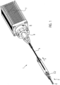
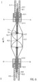
- Figure 1 shows a catheter device 1.
- the catheter device 1 according to the invention represents a pump.
- the catheter device 1 has a pump head 3 at a distal end 2.
- the pump head 3 has a rotor 3.2 for conveying a medium in the conveying direction 5, which is connected to a drive shaft 4.
- the conveying direction 5 is directed from the distal end 2 to a proximal end 6.
- a motor 7 is arranged at the proximal end 6, which is spaced from the pump head 3.
- the drive shaft 4 is surrounded by a catheter shaft 8 and is connected to the motor 7 in a force-fitting manner by means of a coupling 9.
- the pump head 3 is first explained in more detail below.
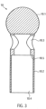
- the pump head 3 comprises a shaft cap 10 at the distal end, the rotor 3.2 arranged on the drive shaft 4, a pump housing 3.1 and an outflow hose 18.
- the butt cap 10 is formed from a ball 10.1 with an attached cylindrical section 10.2.
- the butt cap 10 is made of stainless steel, for example ( Fig.2 , Fig.3 ).
- the butt cap 10 could also be made of polyethylene PE, polypropylene PP, polyetheretherketone PEEK, polyvinyl chloride PVC, Teflon PTFE, acrylic glass, epoxy resin, polyurethane PU, carbon fiber, coated materials, composite materials, PEBAX, a polyether block amide. In principle, all hemocompatible materials are suitable, since only a low mechanical load occurs on this component.
- the diameter of the ball 10.1 is approximately 3.2 mm.
- the cylindrical section 10.2 is approximately 5.5 mm long and has a diameter of approximately 2.2 mm.
- the total length of the butt cap is approximately 7.0 mm.
- the cylindrical section 10.2 has a through hole 10.3 arranged transversely to the conveying direction 5 at its distal end in the connection area to the ball 10.1.
- the cylinder 10.2 also has an axial hole 10.4 which extends from the proximal end of the cylindrical section 10.2 to the ball 10.1, so that a communicating passage is formed from the through hole 10.3 to the proximal end of the shaft cap 10.
- a step 10.5 is formed in the area of the axial hole 10.4, so that the axial hole is widened in the direction of the proximal end.
- the through hole 10.3 prevents a blind hole from being created in the shaft cap and, on the other hand, the through hole allows the attachment of a thread which is helpful when compressing the pump head 3.
- a pigtail, a spiral, a meandering wire with a ball tip or an atraumatic fiber bundle can also be provided. Due to its small size, the butt cap is preferred.
- the tip of the shaft cap 10 is an atraumatic ball to protect the heart muscle (endocardium).
- the pump head 3 can be supported on the heart wall via the shaft cap 10.
- a tubular or hose-shaped distal catheter shaft piece 8.1 is inserted from the proximal end into the shaft cap 10 up to the step.
- the distal catheter shaft piece 8.1 is precisely received in the axial bore 10.4 and is fixed there ( Fig.4 ).
- the distal catheter shaft piece 8.1 is made of polyurethane or another suitable material, in particular an elastic plastic material (e.g. PE, PVC, Teflon, elastomer).
- the distal end of the distal catheter shaft piece 8.1 is connected to the shaft cap 10.
- the connection can be made as an adhesive connection using cyanoacrylate adhesive, for example, or it can be made as a welded, clamped or shrink-fit connection.
- These connecting means are generally suitable for connecting a catheter shaft piece to another, in particular rigid, part. In the following description, this is therefore not carried out at every individual connection point.
- the distal catheter shaft piece 8.1 forms a straight but slightly flexible connection between the shaft cap 10 and the pump housing 3.1.
- the straight connection ensures coaxiality of all components arranged in it (drive shaft, shaft protection, housing, connecting bushing).
- the distal catheter shaft piece 8.1 serves in conjunction with the shaft cap 10 as a positioning aid for the pump head 3 when it is inserted into a vessel or the heart.
- the catheter shaft piece 8.1 in the present embodiment has a length of approximately 25 mm, an outer diameter of approximately 1.9 mm and an inner diameter of approximately 1.3 mm.
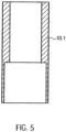
- a distal, tubular connecting sleeve 12.1 is provided ( Fig.5 , Fig.6 ).
- the distal connection bushing 12.1 has a larger inner diameter in the distal area than in the proximal area.
- the proximal end of the distal catheter shaft piece 8.1 is precisely accommodated and fixed in the distal area of the connection bushing 12.1.
- a distal connection section 3.1.1 of the pump housing 3.1 is accommodated in the proximal area of the distal connection bushing 12.1.
- the distal connection section 3.1.1 of the pump housing 3.1 is connected to the distal connection bushing 12.1 and the proximal end of the distal catheter shaft piece 8.1 ( Fig. 7a, Fig. 7b ).
- the distal connecting sleeve 12.1 has a length of approximately 5 mm and an outer diameter of approximately 2.2 mm. In the distal area, the diameter is approximately 2 mm and in the proximal area approximately 1.5 mm. The shorter the connecting sleeve, the less stiffening it provides.
- the distal and an analogously designed proximal connection bushing 12.1, 12.2 are made, for example, of stainless steel, copper, brass, titanium or another suitable metal, of polyethylene (PE), polypropylene (PP), Teflon (PTFE), PEBAX, a polyether block amide, or another suitable material.
- PE polyethylene
- PP polypropylene
- PTFE Teflon
- PEBAX PEBAX
- a polyether block amide or another suitable material.
- the expandable or compressible pump housing 3.1 is a tubular lattice structure 3.1.6 made of Nitinol or another suitable shape memory alloy or another shape memory material, e.g. plastic, iron alloy, copper alloy.
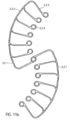
- the pump housing 3.1 is divided into five sections from distal to proximal ( Fig.8 ).
- the first distal section is a tubular distal connecting section 3.1.1.
- a second section is a suction section 3.1.2 which widens conically in the conveying direction 5.
- the suction section 3.1.2 is followed by a pump section 3.1.3.
- the tubular pump section 3.1.3 accommodates the rotor 3.2.
- the inner diameter of the pump section 3.1.3 in the expanded state is approximately 6.15 mm.
- An outlet section 3.1.4 narrows conically in the conveying direction 5 and forms the connection between the pump section 3.1.3 and a proximal connecting section 3.1.5.
- the proximal connecting section 3.1.5 is tubular in shape, analogous to the distal connecting section 3.1.1, with a smaller diameter than the pump section 3.1.3.
- the pump housing 3.1 can be compressed in such a way that it does not exceed a maximum diameter of less than 3 mm over its entire length.
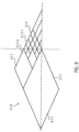
- the lattice structure 3.1.6 of the pump housing 3.1 has openings 3.1.7 between the lattice struts ( Fig.8 , Fig.9 ).
- the openings are designed as polygons 3.1.7, which are diamonds in the present embodiment.
- Small diamonds 3.1.7.1 are provided in the pump section 3.1.3.
- the small diamonds 3.1.7.1 are gradually combined to form larger diamonds.
- a larger diamond with twice the edge length is arranged adjacent to a small diamond. This doubling of the edge length is repeated until the openings have the desired size.
- Large diamonds 3.1.7.2 are provided in the intake section 3.1.2 and the outlet section 3.1.4, which have approximately four times the edge length of the small diamonds 3.1.7.1.
- the large diamonds 3.1.7.2 are combined to form smaller diamonds.
- the distal and proximal connecting sections medium-sized diamonds 3.1.7.3 are provided, which have approximately twice the edge length of the small diamonds 3.1.7.1 ( Fig.9 ).
- the design of the openings 3.1.7 and the number of multiplications can be arbitrary. When moving from smaller to larger diamonds, the width of the lattice struts is increased. This keeps the strength of the lattice struts approximately the same or even reinforced towards the larger diamonds.
- the grid structure 3.1.6 of the pump housing 3.1 is covered with a PU covering 3.1.8 in the pump section 3.1.3, whereby the grid openings are sealed liquid-tight.
- This covering or the sealing of the grid structure 3.1.6 can also be formed, for example, by a PU hose which is arranged on the outside or inside of the surface.
- a covering other than PU can also be used, such as PE, PP, silicone or parylene, as long as it meets the mechanical and geometric requirements.
- the performance parameters of the pump including blood damage, can be specifically controlled.
- the polygonal structure and the special design of the PU covering result in an almost round cross-sectional shape for the pump housing 3.1. In conjunction with the round rotor 3.2, this results in very small gaps between the rotor 3.2 and the pump housing 3.1. This leads to comparatively low blood damage, low leakage currents and good efficiency.
- the lattice structure 3.1.6 results in very good radial and axial stability as well as very good axial compressibility and expandability.
- the special structure makes it very easy to adapt the length and diameter to the performance requirements.
- the proximal connecting section 3.1.5 of the pump housing 3.1 is accommodated in the proximal connecting socket 12.2 and connected to it.
- a tubular proximal catheter shaft piece 8.2 is accommodated and connected to it in the same way as the distal connecting socket 12.1 ( Fig. 7a, Fig. 7b ).
- the same types of connections as described above can be used.
- a distal shaft protector 13.1 and a proximal shaft protector 13.2 are arranged in the axial direction ( Fig.6 ).
- the distal and proximal shaft protection 13.1, 13.2 are designed as a tube made of PU or one of the other materials listed above.
- the distal shaft protection 13.1 extends in the conveying direction 5 from just before the distal connecting bushing 12.1 to the distal end of the pump section 3.1.3 of the pump housing 3.1, i.e. to the rotor 3.2.
- the proximal shaft protection 13.2 extends from the proximal end of the rotor 3.2 to just behind the proximal end of the proximal connecting bushing 12.1.
- the distal and proximal shaft protectors 13.1, 13.2 are connected to the distal and proximal connecting sleeves 12.1, 12.2 and the distal and proximal catheter shaft pieces 8.1, 8.2 in the two areas in which they are arranged within these.
- the connecting bushings 12.1, 12.2 ensure the axial centering of the drive shaft 4, particularly in the pump housing 3.1.
- the drive shaft 4 is arranged in the axial direction within the distal and proximal shaft protection 13.1, 13.2 or the pump housing 3.1.
- the drive shaft 4 has three sections in the conveying direction 5.
- a distal section of the drive shaft 4.1 in the area of the shaft cap 10.
- the rotor 3.2 is glued to the drive shaft.
- other force-fit connections such as welding or clamping can also be provided.
- the proximal shaft protection 13.2 ( Fig.2 , Fig.6 ) separates the proximal section 4.3 of the drive shaft 4 from the pump medium to protect against blood damage caused by the rotational movement of the drive shaft 4 and adhesion of blood components to the drive shaft 4. This means that no shear forces build up. There is no direct interaction between the drive shaft 4 and the blood due to the very small gap and only minimal blood transport is possible through this gap.
- the distal and proximal shaft protection 13.1, 13.2 center and support the drive shaft 4 during operation and during the compression and expansion process.
- the drive shaft 4 is preferably made of several, in particular six wires (not shown), which are wound left or right around a core (not shown).
- the outer diameter of the drive shaft 4 is approximately 0.48 mm.
- the drive shaft 4 can also have a different number of cores and wires and a smaller or larger diameter.
- the diameter of the drive shaft can be in the range from 0.3 mm to 1 mm and is preferably approximately 0.4 mm to 0.6 mm.
- the smaller the diameter of the drive shaft the higher the rotational speed can be, because the smaller the diameter, the lower the speed at which the circumference of the drive shaft moves relative to its surroundings. A high circumferential speed is problematic if the drive shaft comes into contact with the surroundings.
- the catheter device is designed for speeds of more than 20,000 rpm and up to 40,000 rpm.
- the diameter of the drive shaft 4 is therefore made as small as possible, but thick enough that it still has sufficient strength.
- spiral-shaped guide spiral 14 is arranged to minimize the friction of the drive shaft 4, to avoid wall contact of the drive shaft 4 with the proximal catheter shaft piece 8.2 and to prevent the drive shaft 4 from kinking as a result of bending.
- the drive shaft 4 is guided and splinted or stabilized by the guide spiral 14 ( Fig.10 ).
- the guide spiral 14 can be made of stainless steel and glued to the shaft protection 13.1, 13.2. It can also be provided that the guide spiral is designed as a spring.
- the winding direction of the guide spiral 14 can also be the same as the winding direction of the drive shaft 4.
- the drive shaft 4 extends from the distal end of the distal shaft guard 13.1 in the conveying direction 5 behind the distal connecting bush 12.1 to the coupling 9.
- the proximal catheter shaft piece 8.2 in conjunction with the guide spiral 14 provides a length and torsion-constant connection between the pump head 3 and the coupling 9.
- a bearing disk 15 is arranged ( Fig.6 ).
- the bearing disk 15 is provided with a through hole 15.1.
- the diameter of the through hole 15.1 corresponds approximately to the outer diameter of the drive shaft 4.
- the bearing disk 15 is arranged on the drive shaft 4 in such a way that it receives the proximal end of the distal shaft guard 13.1 and limits it in the conveying direction 5.
- the bearing disk 15 is made of stainless steel, Teflon or ceramic, for example, or another suitable material.
- the bearing disk 15 is connected to the fixed shaft guard using cyanoacrylate adhesive and can therefore absorb axial forces against the conveying direction 5 (connecting means see above).
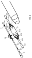
- the spiral-shaped, expandable rotor 3.2 is arranged in a rotationally fixed manner on the drive shaft 4.
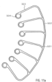
- the rotor 3.2 is a two-winged, comb-shaped frame structure 3.2.1 made of Nitinol or another shape memory material, e.g. plastic (see above), which is coated with a PU skin or surrounded by it in a liquid-tight manner ( Fig. 11a ). This means that the covering in the form of the PU skin is stretched between the comb-shaped frame structure.
- the construction of the rotor 3.2 as a coated frame structure 3.2.1 made of Nitinol makes it possible to expand or compress the rotor 3.2.
- the PU skin has a high elasticity, so that it is not damaged when compressed.
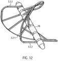
- the frame structure 3.2.1 has a circumferential, helical or spiral outer boundary frame 3.2.2 with several rotor struts 3.2.3 connected to the boundary frame 3.2.2 and extending radially inward ( Fig. 12 ). Rings 3.2.4 are formed at the free ends of the rotor struts 3.2.3.
- the drive shaft 4 extends through the rings 3.2.4 of the rotor struts 3.2.3.
- a spacer sleeve 16 is arranged between each two adjacent rings 3.2.4.
- the distal end of the rotor 3.2 rests against the bearing disk 15 with a distal end spacer sleeve 16.
- the end spacer sleeve 16 can also be designed as a special bearing spacer sleeve 16. In this way, two of the frame structures 3.2.1 form a two-blade rotor 3.2.
- the rotor 3.2 can also be made in one piece ( Fig. 11 b) or have multiple frame structures ( Fig. 11 a) . Each frame structure forms a rotor blade.
- Fig. 11b and 12 a frame structure 3.2.1 for a rotor 3.2 is shown, which forms two rotor blades. If required, several rotor blades and accordingly several frame structures 3.2.1 can be arranged on a rotor 3.2.
- the frame structure can also have any other suitable shape.
- the distance between two adjacent rings 3.2.4 is smaller than the corresponding section of the spiral-shaped limiting frame 3.2.2.
- the pitch of the rotor 3.2 can thus be determined by the length of the spacer sleeves 16. It can vary within a rotor 3.2.
- the pitch of the rotor 3.2 is determined by the length or number of spacer sleeves 16 in relation to the dimensions of the rotating, spiral-shaped outer limiting frame 3.2.2 between two rotor struts 3.2.3.
- the length of the spacer sleeves 16 can be uniform for all positions, but it can also be varied symmetrically or asymmetrically for each position.
- the complete freedom of design allows a very flexible design of the rotor 3.2.
- the flexible design makes it possible to generate different conveying or pumping properties of the rotor 3.2.
- the Rotor 3.2 has a high degree of dimensional stability with flexible design options and minimal use of materials (e.g. thin frame structure). Maximum rigidity and stability is achieved. Nevertheless, the combination of the frame structure with the covering, which further supports the properties of the frame structure through stabilization, allows for very strong compression. This leads to the rotor's very good compressibility and expandability. Due to the good surface formation of the PU skin on the lattice structure, the housing structure can be very well adapted to the rotor structure.
- the rotor 3.2 In the compressed state, the rotor 3.2 has approximately the inner diameter of the compressed pump housing 3.1.
- the outer diameter of the compressed pump housing is approximately between 2 mm and 4 mm and preferably approximately 3.3 mm.
- the spiral-shaped outer limiting frame 3.2.2 of the rotor 3.2 is slightly spaced from the inner surface of the pump housing 3.1.
- the distance between the outer limiting frame 3.2.2 and the inner surface of the pump housing 3.1 is approximately between 0.01 mm and 0.5 mm. The smaller the distance between the frame structure 3.2.1 and the inner surface of the pump housing 3.1, the higher the delivery capacity of the rotor 3.2.
- the distal spacer sleeve 16 of the rotor 3.2 contacts the bearing disk 15 in the manner of a sliding bearing. In this way, a distal rotor bearing 17 is formed ( Fig.6 ).
- the drive shaft 4 is accommodated in the through hole of the bearing disk 15 with almost no play. Only small clearances remain (not shown) due to the design of the drive shaft 4.
- the rotor 3.2 is subjected to an axial force counter to the conveying direction 5 due to the conveying of the pumped medium. This force is diverted to the bearing disk 15 via the distal end spacer sleeve 16.
- the drive shaft 4 is similarly received by a proximal connecting bushing 12.2 on the proximal end spacer sleeve 16 of the rotor 3.2.
- a tubular elastic discharge hose 18 is arranged ( Fig.1 , Fig. 13 ).
- the outflow hose 18 is made of PU.
- the outflow hose 18 has a length of approximately 70 mm, a diameter of approximately 10 mm and a wall thickness of approximately 0.01 mm to 0.1 mm and preferably approximately 0.03 mm.
- the two ends of the outflow hose 18 are tapered, with a cylindrical section being arranged at the proximal conical end of the outflow hose.
- the distal, tapered end of the outflow hose 18 is tightly sealed with the PU covering of the pump section 3.1.3 of the pump housing 3.1.
- the cylindrical proximal section is firmly connected to the proximal catheter shaft piece 8.2. Both are connected to each other in a liquid-tight manner using dissolved PU.
- outlet openings 18.1 are arranged radially all the way around.
- the outlet openings 18.1 can be oval in the conveying direction 5, for example. It can also be provided that the outlet openings are round, crescent-shaped or have any geometry in order to generate other outlet flows.
- the outlet openings 18.1 swirl the blood exiting the bulbus aorticus. This prevents a laminar flow and thus the water jet pump effect in relation to the coronary arteries.
- the outflow tube 18 directs the pump volume from the left ventricle via the aortic valve into the aorta.
- the outflow tube 18 acts like a check valve. If there is a positive pressure difference between the outflow tube 18 and the aorta, the outflow tube 18 is more or less open depending on the flow rate generated by the pump. If the pressure difference is zero or negative, the outflow tube 18 closes just like the aortic valve due to its high flexibility and fits tightly against the proximal catheter shaft piece 8.2. This flexibility leads to a good seal during the flow against the leaflets of the aortic valve. In this way, only minimal backflow from the aorta into the left ventricle occurs.
- the coupling 9 and the motor 7 are arranged at the proximal end of the catheter shaft 8.2.
- the distance between the pump head 3 and the coupling 9 or the length of the proximal catheter shaft section 8.2 can vary depending on the patient and is approximately 90 to 150 cm.
- a tubular cover tube 29 is arranged above the catheter device 1.
- the cover tube 29 is designed such that it surrounds the compressed pump head 3 and the proximal catheter shaft piece 8.2.
- the cover tube 29 holds the pump head 3 in its compressed state.
- the cover tube 29 is pulled back from the fixed catheter device 1 until the pump head 3 is exposed.
- the pump housing 3.1 and rotor 3.2 expand radially outwards due to the spring force of the elastic material. This means that the grid structure 3.1.6 of the pump housing 3.1 and the frame structure 3.2.1 of the rotor 3.2 expand until they have reached their predetermined diameter. It can also be provided to use temperature effects of the memory material to support the expansion.
- the cover tube 29 is advanced to the shaft cap 10, whereby the rotor 3.2 and the pump housing 3.1 are compressed and drawn into the cover tube, after which the latter is extracted through the puncture site.
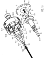
- the clutch 9 is a magnetic clutch ( Fig. 14 , Fig. 15 ).
- the coupling 9 has a coupling housing 19 with a distal magnet unit 23.1.
- the coupling housing 19 is connected to the proximal catheter shaft piece 8.2, which forms a continuous cavity.
- the coupling housing 19 hermetically separates the proximal catheter shaft piece 8.2 from a motor arrangement 30.
- the motor arrangement 30 has a proximal magnet unit 23.2.
- the proximal magnet unit 23.2 is non-positively connected to the motor 7.
- the distal magnet unit 23.1 is connected to the drive shaft 4 via a coupling element 22.
- the distal magnet unit 23.1 and the proximal magnet unit 23.2 are coupled to one another in a rotationally fixed manner via magnetic forces.
- the two magnet units 23.1, 23.2 ensure a force-locking connection with contact-free rotational force transmission.
- the coupling housing 19 has, from distal to proximal, a distal cylindrical section 19.1, a conically widening section 19.2, a second cylindrical section 19.3 and a proximal cylindrical section 19.4.
- the coupling housing is made, for example, from polymethyl acrylate (PMMA) or another material that can be injection molded or machined.
- a through hole is formed in the distal cylindrical section 19.1, arranged centrally in the axial direction.
- the through hole extends through the entire coupling housing 19.
- the through-bore narrows in three stages from a first catheter shaft receiving section 19.5 to a second guide spiral receiving section 19.6 and to a third drive shaft passage section 19.7.
- the bore diameter of the catheter shaft receiving section 19.5 is approximately 1.9 mm, that of the guide coil receiving section 19.6 is approximately 1.28 mm and that of the third bore section is approximately 1.0 mm.
- the proximal end of the proximal catheter shaft is arranged in the catheter shaft receiving section 19.5 of the coupling housing 19 and is firmly connected thereto.
- the guide spiral 14 is accommodated in the guide spiral receiving section 19.6.
- the drive shaft 4 extends through the through hole of the drive shaft passage section 19.7 of the distal cylindrical section 19.1 and the conically widening section 19.1, 19.2.
- the drive shaft passage section 19.7 widens in the conically widening section 19.2 into a fourth bore section 19.8.
- the fourth bore section merges into a hollow cylindrical bearing section 19.9 at the beginning of the second cylindrical section 19.3.
- An outer ring magnet 20.1 is arranged in the distal end region of the bearing section 19.9.
- the outer ring magnet 20.1 is fixed in the bore of the bearing section 19.9 by means of a press fit and can additionally or alternatively be fixed by means of an adhesive.
- the bearing section 19.9 has a diameter of approximately 10 mm.
- a pump (not shown) is connected to the flushing bore for introducing a medium, e.g. NaCl, glucose solution, Ringer's solution, plasma expander, etc.
- a medium e.g. NaCl, glucose solution, Ringer's solution, plasma expander, etc.
- the bore of the distal coupling section 19.10 merges into a larger proximal coupling section 19.11.
- 19.11, 8 x M 1.6 threaded holes 19.13 are formed radially symmetrically.
- three L-shaped milled recesses 19.14 are arranged, distributed around the circumference.
- the distal coupling section 19.10 has a diameter of approximately 22 mm.
- the flushing bore 19.15 has a diameter of approximately 6.5 mm and the proximal coupling section 19.11 has a diameter of approximately 30 mm.
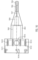
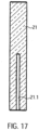
- the proximal end of the drive shaft 4 is connected to a cuboid-shaped square rod 21 in a rotationally, tensile and compressively resistant manner (force-locking) ( Fig.17 ).
- the square rod 21 has a recess 21.1 for receiving the proximal end of the drive shaft 4.
- the drive shaft 4 is fixed in the recess.
- the square rod 21 is made of brass, for example, which has good lubricating properties. Other suitable materials are all materials that can be extruded or machined, such as PE, PP, PTFE, gold, silver, titanium, diamond, etc.
- the square bar 21 has a length of approximately 19.4 mm and a cross-section of approximately 2.88 mm x 2.88 mm.
- the square rod 21 transmits the rotary motion of the motor to the drive shaft.
- the square rod 21 can have any geometric shape that allows a statically determined force input.
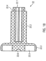
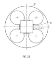
- the square rod 21 is axially displaceably received in an axial recess 22.1 within a rotationally symmetrical coupling element 22 ( Fig. 23 ). This enables it to compensate for length differences in the axial direction ( Fig. 18 ).
- the recess 22.1 is formed by a larger, central bore and four smaller bores arranged along the circumference of the central bore.
- the bores can be formed by drilling, erosion, ultrasonic drilling, laser drilling or water jet drilling.
- the arrangement of the holes provides four axially extending double stop edges.
- the recess 22.1 is arranged within a cylindrical section 22.2 of the coupling element 22 and extends from the distal end of the coupling element 22 to just before a disk-shaped proximal section 22.3 of the coupling element 22.
- the cylindrical section 22.2 has an outer diameter of approximately 8 mm and the disk-shaped section 22.3 has an outer diameter of approximately 18 mm.
- the recess 22.1 is designed in such a way that the square bar 21 is fixed radially or in the circumferential direction and accommodated in an axially displaceable manner.
- the radial fixation of the square bar 21 is achieved by contacting all four longitudinal edges of the square bar 21 with one of the four double stop edges of the recess 22.1.
- More or fewer stop edges can also be provided.
- a square bar for example, a triangular or pentagonal bar or a profile bar with any cross-sectional area that remains constant in the longitudinal direction of the bar can be provided.
- the shape of the recess 22.1 must be adapted to the cross-sectional area of the profile bar.
- a shoulder 22.4 is formed on the distal outer end or circumference of the cylindrical section 22.2 of the coupling element 22.
- a second inner ring magnet 20.2 is arranged on this shoulder 22.4.
- the shoulder 22.4 accommodates the ring magnet 20.2 in such a way that its outer surface is flush with the outer surface of the cylindrical section 22.2.
- this forms a magnetic ring bearing 20.3.
- the two ring magnets 20.1, 20.2 are arranged in such a way that, for example, the north pole of the outer ring magnet is oriented distally and the south pole is oriented proximally.
- the north and south poles of the inner ring magnet are designed in opposite directions. Accordingly, the north and south poles of the two ring magnets can also be arranged in reverse.
- the magnetic ring bearing 20.3 centers the drive shaft 4 in the axial and radial directions. Radial centering is achieved by the magnetic attraction forces in the radial direction.
- Axial centering is achieved by generating magnetic restoring forces when the inner ring magnet 20.2 is slightly offset, which pull the inner ring magnet 20.2 into a position that corresponds to the position of the outer ring magnet 20.1 in the axial direction. With a larger offset, however, repulsive forces occur between the two magnetic rings 20.1 and 20.2, which pushes them apart.
- the ring magnets 20.1, 20.2 do not touch each other, i.e. no lubrication is required.
- the magnetic ring bearing also has a vibration-damping effect.
- a magnet holder 22.5 is formed in the disk-shaped section 22.3 of the magnetic coupling element 22.
- the magnet holder 22.5 is a centric circular milled recess.
- the centric circular milling 22.5 has a diameter of approximately 16.5 mm and a depth of approximately 3 mm.
- the magnet holder 22.5 holds the ring-shaped distal magnet unit 23.1, which consists of four segments.
- the ring-shaped distal magnet unit is glued into the magnet holder 22.5.
- a ball head bearing holder 22.6 is formed centrally in the proximal end face of the coupling element 22.
- the ball head bearing holder 22.6 is an approximately hemispherical recess 22.6.
- the hemispherical recess 22.6 has a diameter of approximately 0.5 to 1.3 mm.
- the square rod 21 or the cylindrical section of the coupling element 22 is received by the fourth bore section 19.8 or the bearing section 19.9 of the coupling housing 19.
- the disk-shaped section 22.3 of the coupling element 22 is received by the distal coupling section 19.10 of the coupling housing 19.
- the clutch housing 19 is hermetically separated from the engine assembly by a cover plate 24 ( Fig. 19 ).
- the clutch housing 19 is gas and liquid tight except for the flushing bore 19.15 in the clutch housing 22 and the free spaces between the drive shaft passage section 19.7 and the drive shaft 4.
- the cover plate 24 is arranged on the shoulder 19.12 of the coupling housing 19 and is fixed by means of eight screws, which are received in corresponding radially symmetrically arranged holes 24.1 in the cover plate 24 and are screwed into the threaded holes 19.13 of the coupling housing 19. This connection is designed to be liquid and gas tight.
- the cover plate 24 is made, for example, from polymethyl acrylate (PMMA) or another non-metallic material (such as Peek, PEBAX, Teflon, PP, PE, all injection-moldable, extrudable or machined, non-magnetic materials).
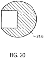
- the cover plate 24 On the distal side, the cover plate 24 has a central thickening 24.2. In the center of the cover plate 24 there is a through hole 24.3 and a central hemispherical milling 24.4. A cylindrical centering pin 24.5 is fixed in the through hole 24.3 ( Fig.21 ). A ball head 24.6 is arranged on the centering pin 24.5 and is accommodated in the hemispherical milling ( Fig. 15 , Fig. 20 ).
- the distal magnet unit 23.1 is subjected to a force in the proximal direction. These opposing forces cause a resulting force with which the coupling element 22 is pressed against the ball head 24.6. This resulting force is adjusted so that the ball head 24.6 is securely mounted and yet the wear in the ball head bearing is kept to a minimum.
- the ball head 24.6 forms a ball head bearing 25 in conjunction with the distally arranged ball head bearing holder 22.7 of the coupling element 22.
- the ball head bearing 25 is a plain bearing.
- other plain bearings are also possible, such as a conical head bearing or a cylinder head bearing, in which a cone or a cylinder is provided as the bearing body instead of the ball.
- the holder is adapted to the shape of the bearing body.
- the axial centering of the magnetic ring bearing 20.3 is achieved by the inner ring magnet 20.2 not being positioned exactly in the middle of the outer ring magnet 20.1 in the axial direction, but being slightly offset proximally. This means that the inner ring magnet 20.2 is subjected to a force in a distal direction.
- the ball head 24.6 can be made of ruby, aluminum oxide or a hard plastic.
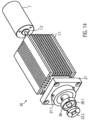
- the motor assembly comprises the proximal magnet unit 23.2, a proximal magnet holder 26, a coupling flange 27, a motor holder 7.1, with a cooling fan arranged thereon and the motor 7 ( Fig. 14 , Fig. 22 ).
- a proximal magnet unit 23.2 is arranged axially aligned with the distal magnet unit 23.1 at a distance of approximately 0.5 to 8 mm and preferably approximately 1 to 2 mm.
- the proximal ring-shaped magnet unit 23.2 has four segments, analogous to the distal magnet unit 23.1.
- the magnet holder 26 is disk-shaped and has a central circular milling 26.1 on its distal side. Analogous to the distal magnet unit 23.1, four magnet segments are glued into the milling 26.1 using two-component epoxy resin adhesive or cyanoacrylate adhesive (see above).
- the four segments of the distal and proximal magnet units 23.1, 23.2 can be designed as curved bar magnets, each of which has a different polarity at its end.
- the four segments can also be designed as four quarters of a curved ring magnet.
- the segments can also be designed as short, axially aligned bar magnets that are arranged in a ring shape. More than four segments can also be provided. In the starting position, the two magnets are arranged in such a way that a north and a south pole of the bar magnets of the two magnet units 23.1, 23.2 overlap and attract each other.
- the four segments are arranged four times with their north and south poles alternating in abutment so that the segments of a magnet unit attract each other.
- the distal and proximal magnet units 23.1, 23.2 are arranged in such a way that complementary poles are arranged opposite each other. This causes the two magnet units to attract each other and a torque can be transmitted because the magnetic forces want to maintain this complementary pole arrangement.
- the centric circular milling 26.1 has a diameter of approximately 16.5 mm and a depth of approximately 3 mm.
- the magnet holder 26 is connected to a motor shaft 7.2 of the motor 7.
- the magnet holder 26 is arranged rotatably within a correspondingly shaped recess in the coupling flange 27 of the motor holder.
- Three dowel pins 27.1 are arranged evenly spaced along the outer circumference of the annular web of the recess.
- the clutch housing 19 is connected to the dowel pins 27.1 of the clutch flange 27 of the motor assembly via the L-shaped millings 19.14 of the clutch housing 19.
- the coupling flange 27 is attached to a distal end face 7.1.1 of the motor mount while maintaining axial symmetry.
- the motor mount 7.1 is a cuboid-shaped body, on whose side surfaces 7.1.2 cooling fins 7.1.3 are arranged.
- the motor mount 7.1 has a centrally arranged bore 7.1.4 in the axial direction. This The motor shaft 7.2 is guided in bore 7.1.4. An axially aligned recess 7.1.5 is also provided in which the motor 7 is arranged.
- the motor 7 is, for example, a standard electric motor from Faulhaber with an output of 38 W at 30,000 rpm or another suitable motor.
- a cooling fan is arranged on a side surface 7.1.2 of the cuboid-shaped motor mount 7.1.
- a cover tube 29 is arranged above the pump head 3 and a distal region of the proximal catheter shaft piece.
- the cover tube 29 has an inner diameter which, in the region of the pump head 3, corresponds to the outer diameter of the non-expanded pump housing.
- the outer diameter of the cover tube is approximately 3 mm.
- the two magnet units 23.1, 23.2 are spatially separated from one another by the cover plate 24 in the clutch housing 19.
- the magnetic attraction forces between the two magnet units 23.1, 23.2 create a force-locking connection.
- Opposite poles of the two magnet units 23.1, 23.2 face each other, causing them to attract one another and forming a non-rotating force-locking connection.
- the ball head bearing holder 22.7 of the coupling element 22 is pressed onto the ball head 24.6 of the cover plate 24 and forms the ball head bearing 25.
- the ball head bearing centers the axial run of the drive shaft 4.
- the inner ring magnet 20.1 is guided radially at a constant distance in the outer ring magnet 20.2.
- the magnetic ring bearing 20.3 in conjunction with the ball head bearing 25 centers and guides the rotationally symmetrical running of the coupling element 22 or the drive shaft 4 in order to prevent impacts or imbalance.
- the motor shaft 7.2 rotates at a speed of approximately 20,000 rpm to 40,000 rpm and preferably approximately 32,000 rpm to 35,000 rpm, which is transmitted to the drive shaft 4.
- the rotor 3.2 has a delivery capacity of approximately 2 l/min to 2.5 l/min at a differential pressure of 60 mm Hg.
- the drive shaft 4 twists or shortens and the resistance at the distal magnet unit 23.1 increases.
- the magnetic fields between the proximal and distal magnet units 23.2, 23.1 do not completely overlap during operation because the distal magnet unit 23.1 always lags behind the proximal magnet unit 23.2 a little. If the torque required at the distal magnet unit 23.1 increases, the north and south poles of the magnet units 23.1, 23.2 no longer overlap but repel each other. This causes the distal magnet unit 23.1 to be pushed distally by the proximal magnet unit 23.2. The magnetic connection between the two magnet units 23.1, 23.2 is severed. The drive shaft 4 immediately stops.
- the inner ring magnet 20.2 of the coupling element 22 is also moved in the distal direction and the north and south poles of the two ring magnets 20.1, 20.2 of the magnetic ring bearing 20.3 no longer overlap but repel each other. This keeps the coupling 9 in the decoupled state and results in a permanent decoupling of the motor 7 and drive shaft 4.
- the amount of torque that can be transmitted is limited by the magnetic ring bearing 20.3 or the magnetic connection between the two magnet units 23.1, 23.2. As soon as the set torque is exceeded, the two magnet units 23.1, 23.2 separate. The distal magnet unit 23.1 can no longer keep up with the proximal magnet unit 23.2 due to the rapid rotation, as the magnetic binding forces are no longer sufficient. As a result, the north and south poles no longer overlap and the magnet units 23.1, 23.2 repel each other. The connection between the magnet units 23.1, 23.2 is separated and the maximum torque that can be transmitted is limited. The magnet units 23.1, 23.2 are held in the decoupled state by the magnetic ring bearing 20.3 through the mutual repulsion of the ring magnets 20.1, 20.2.
- This state can be changed again by applying an external magnetic field.
- the two magnet units 23.1, 23.2 can be brought back into their coupled starting position.
- the clutch housing 19 and the motor arrangement 30 are spatially separated from one another. This makes it possible to lubricate the drive shaft 4 via the pump arranged on the flushing bore 19.15 at around 5-10 ml/h despite the high speed in order to minimize friction. It can also be provided to introduce an infusion via the flushing bore 19.15, which also lubricates the drive shaft 4.
- the small diameter of the drive shaft is advantageous at high speeds of around 32,000 rpm. With larger diameters, the peripheral speed would be too high and friction could lead to Damage to the drive shaft 4 or the adjacent components may occur.
- the arrangement of the ball head bearing 25 (plain bearing), the magnetic ring bearing 20.3 (contact-free, damping and centering) and the axial plain bearing between the drive shaft 4 and the clutch housing 19 results in three stabilization points.
- a change in length occurs, for example, when the pump head 3 is compressed.
- the rotor 3.2 is compressed, folded around the drive shaft and clamped in the housing.
- the pump housing 3.1 extends proximally. The drive shaft 4 can move so far that it is not torn off the rotor 3.2.
- the ability to move the drive shaft 4 allows the length change of the PU catheter shaft due to fluid absorption, temperature differences, and bending of the catheter shaft 8.2, which affect the length ratios between the drive shaft 4 and the catheter shaft 8.2, to be compensated. This mechanism is possible due to the ability to move the square rod 21 within the axial recess 22.1.
- the pump head 3 is arranged in the left ventricle in such a way that the outflow tube 18 is arranged approximately in the middle of the transition from the aorta to the heart, i.e. in the area of the heart valve.
- the catheter device 1 is preferably designed in such a way that it can generate a certain pump pressure in the range of approximately 100 mm Hg to 150 mm Hg. If the heart is in systole, the catheter device pumps blood if the pressure built up by the heart is less than the pump pressure. A diseased heart is thus relieved. During diastole, an opposite pressure difference exists. If the pressure difference is greater than the pump pressure, the catheter device cannot pump blood. The outflow tube is compressed by the heart valve so that it is sealed. If the pressure difference is less than the pump pressure, however, some blood is pumped against the pressure difference.
- Fig. 24 shows the positioned catheter device 1 for left heart support.
- the pump head 3 is located completely in the left ventricle.
- the outflow tube extends through the heart valve.
- a cover tube 29 is first guided into the left ventricle using a guide wire (Seldinger technique). The guide wire is then removed from the cover tube.
- the catheter device 1 is inserted through the cover tube with the compressed and cooled pump housing 3.1 and rotor 3.2 until the catheter device 1 with the pump head 3 has reached the left ventricle. The device is deployed by pulling the cover tube 29 back on the fixed catheter shaft 8 until the tip of the cover tube 29 has released the pump head 3.
- the cover tube 29 is advanced to the shaft cap 10, whereby the rotor 3.2 and pump housing 3.1 are drawn into the cover tube 29 in a compressed state, after which the cover tube is extracted through the puncture site.
- the bearing disk 15 is arranged on the proximal side of the rotor 3.2.
- the distal conveying direction can be achieved either by reversing the direction of rotation compared to the above embodiment or by reversing the pitch of the rotor 3.2.
- the discharge hose 18 is arranged at the distal end of the pump section of the pump housing 19 and extends distally beyond the pump head. To stiffen the discharge hose 18, the discharge hose can have a grid structure made of a shape memory material, e.g. similar to that of the pump housing.
- the shaft cap 10 extends beyond the distal end of the discharge hose.
- the pump medium flows through the outlet openings of the pump housing, which now serve as inlets, into the pump housing and passes through the inlet opening of the pump housing, which now serves as outlet, into the outflow hose 18.
- the pump medium exits the catheter device 1 via the distal end of the outflow hose.
- the embodiment just described can, for example, be intended for use in the right ventricle.
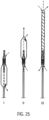
- the catheter device according to the invention can also be designed in such a way that pumping from distal to proximal and from proximal to distal is possible ( Fig. 25 (III).
- bearing disks 15 are provided at the distal and proximal ends of the rotor 3.2.
- the discharge hose 18 is arranged at the distal end of the pump section 3.1.3 of the pump housing 3.1 and extends in the distal direction.
- the discharge hose 18 has a grid structure for stiffening, e.g. similar to the pump housing.
- the grid structure is covered with a PU skin.
- the diameter of the discharge hose corresponds approximately to that of the expanded pump housing.
- a pumped medium can enter or exit through the outlet openings of the pump housing.
- the pump medium then enters the outflow hose, for example, via the outlet openings of the pump housing and the inlet openings of the pump housing and exits at the distal end of the outflow hose. If the pumping direction is reversed, the flow through the catheter device is reversed accordingly. This means that the pump medium enters the outflow hose at the distal end of the outflow hose and reaches the outlet openings of the pump housing via the inlet opening of the pump housing. This allows distal or proximal flow through the pressure and suction-stabilized outflow hose 18.
- the embodiment just described can be used, for example, for drainage or for filling hollow organs or spaces.
- the reversal of the conveying direction can be achieved on the one hand by reversing the direction of rotation of the rotor and on the other hand by reversing the pitch of the rotor.
- the magnet units each have four curved bar magnets, each of which is placed against one another with opposite poles.
- the magnet units can also be designed such that the north and south poles of the magnet units are aligned in the axial direction, with the poles being arranged on the axially distal and proximal surfaces.
- the magnets are arranged in a ring shape in accordance with the previous embodiments.
- Such a coupling can be used, for example, to drive a milling head instead of a rotor.
- a milling head instead of a rotor.
- kidney stones or bones can be milled in a minimally invasive manner.
- the number of magnets can basically be varied as desired.
- the radial compressibility of the components allows the realization of a puncture diameter that is acceptable for percutaneous implantation using the Seldinger technique, due to the very small diameter of the catheter device of around 3 mm.
- the rotor after the WO 99/44651 has an elastic band to connect the ends of a Nitinol coil to a rotation axis.
- This elastic connection means that the coil is not perfectly centered. This causes vibrations when pumping, which make higher speeds or flow rates impossible.
- the frame structure of the rotor with limiting frame and rotor struts according to the catheter device 1 makes the rotor more stable, foldable and can be expanded to almost any diameter. Since the rotor can be made to be almost any length in the longitudinal direction, the radial extension of the rotor can be freely selected. This means that any desired, particularly very high, delivery capacity can be achieved and it is possible to individually adapt the delivery capacity for each application.
- the pitch of the rotor can also be varied as desired.
- the rotor can be designed with one or more rotor blades, whereby the rotor blades have a quarter, a half, a whole or any number of wraps around the drive shaft.
- This means that the rotor according to the invention can be varied as desired in terms of its size, shape and pitch and can therefore be used for a wide variety of applications.
Landscapes
- Health & Medical Sciences (AREA)
- Heart & Thoracic Surgery (AREA)
- Engineering & Computer Science (AREA)
- Life Sciences & Earth Sciences (AREA)
- General Health & Medical Sciences (AREA)
- Anesthesiology (AREA)
- Biomedical Technology (AREA)
- Hematology (AREA)
- Cardiology (AREA)
- Animal Behavior & Ethology (AREA)
- Mechanical Engineering (AREA)
- Public Health (AREA)
- Veterinary Medicine (AREA)
- Vascular Medicine (AREA)
- External Artificial Organs (AREA)
- Endoscopes (AREA)
- Eye Examination Apparatus (AREA)
- Non-Portable Lighting Devices Or Systems Thereof (AREA)
Claims (13)
- Dispositif de cathéter, comprenant- un arbre d'entraînement (4) qui est connecté, à son extrémité proximale, à un moteur (7),- un rotor hélicoïdal compressible et extensible (3.2) qui, à la partie d'extrémité distale, est fixé à l'arbre d'entraînement (4), le rotor (3.2) pouvant, après une compression forcée, se déployer de manière autonome,caractérisé par le fait- que l'inclinaison du rotor (3.2) varie à l'intérieur du rotor (3.2).- que le rotor (3.2) présente une structure de cadre (3.2.1) qui se déploie, après une compression forcée, de manière autonome, étant réalisée en un matériau élastique, qui se compose d'un cadre de délimitation hélicoïdal (3.2.2) et de bretelles de rotor (3.2.3) s'étendant vers l'intérieur du cadre de délimitation (3.2.2) vers l'arbre d'entraînement (4),dans lequel- les bretelles de rotor (3.2.3) sont fixées par leurs extrémités éloignées du cadre de délimitation (3.2.2) à l'arbre d'entraînement (4),- un entoilage élastique s'étend entre le cadre de délimitation (3.2.2) et l'arbre d'entraînement (4), et- au moins un manchon d'écartement (16) est disposé sur l'arbre d'entraînement (4) entre chaque deux bretelles de rotor (3.2.3).
- Dispositif de cathéter selon la revendication 1,
caractérisé par le fait- que l'inclinaison du rotor (3.2) dans la section entre deux bretelles de rotor (3.2.3) est définie par la différence entre la distance entre les deux bretelles de rotor (3.2.3) sur l'arbre d'entraînement (4) et le segment correspondant du cadre de délimitation hélicoïdal (3.2.2) entre les deux les bretelles de rotor (3.2.3). - Dispositif de cathéter selon la revendication 1 ou 2,
caractérisé par le fait- qu'aux extrémités libres des bretelles de rotor (3.2.3) sont réalisés des anneaux (3.2.4), l'arbre d'entraînement (4) s'étendant à travers les anneaux (3.2.4) des bretelles de rotor (3.2.3). - Dispositif de cathéter selon l'une des revendications 1 à 3,
caractérisé par le fait- que les manchons d'écartement (16) présentent une longueur différente. - Dispositif de cathéter selon l'une des revendications 1 à 4,
caractérisé par le fait- que les manchons d'écartement (16) sont réalisés plus courts que la distance entre les points de connexion de deux bretelles de rotor voisines (3.2.3) au cadre de délimitation (3.2.2). - Dispositif de cathéter selon l'une des revendications 1 à 5,
caractérisé par le fait- que l'extrémité distale du rotor (3.2) s'appuie par un manchon d'écartement à l'extrémité distale (16) contre un disque de palier (15). - Dispositif de cathéter selon l'une des revendications 1 à 6,
caractérisé par le fait- que la longueur des manchons d'écartement (16) est variable de manière asymétrique pour chaque position. - Dispositif de cathéter selon l'une des revendications 1 à 7,
caractérisé par le fait- que la structure de cadre (3.2.1) du rotor (3.2) est réalisée en un matériau à mémoire de forme, le matériau à mémoire de forme étant du nitinol ou un autre alliage à mémoire de forme appropriée ou un autre matériau à mémoire de forme tel que par exemple une matière plastique, un alliage de fer ou un alliage de cuivre. - Dispositif de cathéter selon l'une des revendications 1 à 8,
caractérisé par le fait- que la structure de cadre (3.2.1) forme une aile de rotor. - Dispositif de cathéter selon l'une des revendications 1 à 9,
caractérisé par le fait- que le rotor (3.2) présente plusieurs structures de cadre (3.2.1). - Dispositif de cathéter selon l'une des revendications 1 à 10,
caractérisé par le fait- que le rotor (3.2) présente plusieurs ailes de rotor. - Dispositif de cathéter selon l'une des revendications 19 or 11,
caractérisé par le fait- que les ailes de rotor s'étendent sur une plage d'angle d'enveloppement de 45° à 720° et, de préférence, de 360° autour de l'arbre d'entraînement (4). - Dispositif de cathéter selon l'une des revendications 1 à 12,
caractérisé par le fait- que l'entoilage élastique du rotor (3.2) est réalisé en un revêtement polymère tel que par exemple PU, PE, PP, silicone ou parylène.
Applications Claiming Priority (3)
| Application Number | Priority Date | Filing Date | Title |
|---|---|---|---|
| EP07019658A EP2047873B1 (fr) | 2007-10-08 | 2007-10-08 | Dispositif de cathéter |
| PCT/EP2008/007015 WO2009046789A1 (fr) | 2007-10-08 | 2008-08-27 | Mécanisme de cathéter |
| EP08785716.5A EP2217300B1 (fr) | 2007-10-08 | 2008-08-27 | Mécanisme de cathéter |
Related Parent Applications (3)
| Application Number | Title | Priority Date | Filing Date |
|---|---|---|---|
| EP08785716.5A Division EP2217300B1 (fr) | 2007-10-08 | 2008-08-27 | Mécanisme de cathéter |
| EP08785716.5A Division-Into EP2217300B1 (fr) | 2007-10-08 | 2008-08-27 | Mécanisme de cathéter |
| EP08785716.5 Division | 2008-08-27 |
Publications (3)
| Publication Number | Publication Date |
|---|---|
| EP2301598A1 EP2301598A1 (fr) | 2011-03-30 |
| EP2301598B1 EP2301598B1 (fr) | 2017-07-05 |
| EP2301598B2 true EP2301598B2 (fr) | 2024-06-19 |
Family
ID=39049395
Family Applications (11)
| Application Number | Title | Priority Date | Filing Date |
|---|---|---|---|
| EP07019658A Active EP2047873B1 (fr) | 2007-10-08 | 2007-10-08 | Dispositif de cathéter |
| EP10008270.0A Active EP2301598B2 (fr) | 2007-10-08 | 2008-08-27 | Dispositif de cathéter |
| EP17162607.0A Active EP3216467B1 (fr) | 2007-10-08 | 2008-08-27 | Dispositif de cathéter |
| EP15002837.1A Active EP3000493B2 (fr) | 2007-10-08 | 2008-08-27 | Dispositif de catheter |
| EP08785716.5A Active EP2217300B1 (fr) | 2007-10-08 | 2008-08-27 | Mécanisme de cathéter |
| EP10008268.4A Active EP2298374B1 (fr) | 2007-10-08 | 2008-08-27 | Dispositif de cathéter |
| EP10008271.8A Active EP2308524B2 (fr) | 2007-10-08 | 2008-08-27 | Dispositif de cathéter |
| EP17151182.7A Pending EP3187210A1 (fr) | 2007-10-08 | 2008-08-27 | Dispositif de cathéter |
| EP18186035.4A Pending EP3427770A1 (fr) | 2007-10-08 | 2008-08-27 | Mécanisme de cathéter |
| EP10008272.6A Active EP2345440B1 (fr) | 2007-10-08 | 2008-08-27 | Dispositif de cathéter |
| EP15002836.3A Active EP3000492B2 (fr) | 2007-10-08 | 2008-08-27 | Dispositif de catheter |
Family Applications Before (1)
| Application Number | Title | Priority Date | Filing Date |
|---|---|---|---|
| EP07019658A Active EP2047873B1 (fr) | 2007-10-08 | 2007-10-08 | Dispositif de cathéter |
Family Applications After (9)
| Application Number | Title | Priority Date | Filing Date |
|---|---|---|---|
| EP17162607.0A Active EP3216467B1 (fr) | 2007-10-08 | 2008-08-27 | Dispositif de cathéter |
| EP15002837.1A Active EP3000493B2 (fr) | 2007-10-08 | 2008-08-27 | Dispositif de catheter |
| EP08785716.5A Active EP2217300B1 (fr) | 2007-10-08 | 2008-08-27 | Mécanisme de cathéter |
| EP10008268.4A Active EP2298374B1 (fr) | 2007-10-08 | 2008-08-27 | Dispositif de cathéter |
| EP10008271.8A Active EP2308524B2 (fr) | 2007-10-08 | 2008-08-27 | Dispositif de cathéter |
| EP17151182.7A Pending EP3187210A1 (fr) | 2007-10-08 | 2008-08-27 | Dispositif de cathéter |
| EP18186035.4A Pending EP3427770A1 (fr) | 2007-10-08 | 2008-08-27 | Mécanisme de cathéter |
| EP10008272.6A Active EP2345440B1 (fr) | 2007-10-08 | 2008-08-27 | Dispositif de cathéter |
| EP15002836.3A Active EP3000492B2 (fr) | 2007-10-08 | 2008-08-27 | Dispositif de catheter |
Country Status (7)
| Country | Link |
|---|---|
| EP (11) | EP2047873B1 (fr) |
| CN (2) | CN102805885B (fr) |
| AT (1) | ATE491483T1 (fr) |
| CA (5) | CA3020253C (fr) |
| DE (6) | DE502007005973D1 (fr) |
| ES (1) | ES2901005T3 (fr) |
| WO (1) | WO2009046789A1 (fr) |
Families Citing this family (133)
| Publication number | Priority date | Publication date | Assignee | Title |
|---|---|---|---|---|
| US7393181B2 (en) | 2004-09-17 | 2008-07-01 | The Penn State Research Foundation | Expandable impeller pump |
| CN101448535B (zh) | 2006-03-23 | 2011-10-19 | 宾州研究基金会 | 带有可膨胀叶轮泵的心脏辅助装置 |
| US8489190B2 (en) | 2007-10-08 | 2013-07-16 | Ais Gmbh Aachen Innovative Solutions | Catheter device |
| ATE491483T1 (de) | 2007-10-08 | 2011-01-15 | Ais Gmbh Aachen Innovative Solutions | Katheter-vorrichtung |
| US8439859B2 (en) | 2007-10-08 | 2013-05-14 | Ais Gmbh Aachen Innovative Solutions | Catheter device |
| EP2194278A1 (fr) | 2008-12-05 | 2010-06-09 | ECP Entwicklungsgesellschaft mbH | Pompe à fluide dotée d'un rotor |
| EP2216059A1 (fr) | 2009-02-04 | 2010-08-11 | ECP Entwicklungsgesellschaft mbH | Dispositif de cathéter doté d'un cathéter et d'un dispositif d'actionnement |
| EP2229965A1 (fr) | 2009-03-18 | 2010-09-22 | ECP Entwicklungsgesellschaft mbH | Pompe à fluide dotée d'une forme spéciale de lame de rotor |
| EP2246078A1 (fr) | 2009-04-29 | 2010-11-03 | ECP Entwicklungsgesellschaft mbH | Agencement d'arbres doté d'un arbre se déroulant à l'intérieur d'une enveloppe rempli de fluide |
| EP2248544A1 (fr) | 2009-05-05 | 2010-11-10 | ECP Entwicklungsgesellschaft mbH | Pompe à fluide à diamètre modifiable, notamment à des fins médicales |
| EP2266640A1 (fr) | 2009-06-25 | 2010-12-29 | ECP Entwicklungsgesellschaft mbH | Pale comprimable et extensible pour une pompe à fluide |
| EP2448613B1 (fr) * | 2009-07-01 | 2019-11-06 | The Penn State Research Foundation | Pompe pour le sang pourvue d'une canule extensible |
| EP2282070B1 (fr) | 2009-08-06 | 2012-10-17 | ECP Entwicklungsgesellschaft mbH | Dispositif de cathéter doté d'un dispositif d'accouplement pour un dispositif d'entraînement |
| EP2298373A1 (fr) | 2009-09-22 | 2011-03-23 | ECP Entwicklungsgesellschaft mbH | Pompe à fluide dotée d'au moins une aube directrice et d'un dispositif d'appui |
| EP2298372A1 (fr) * | 2009-09-22 | 2011-03-23 | ECP Entwicklungsgesellschaft mbH | Rotor pour une pompe axiale pour le transport d'un fluide |
| EP2299119B1 (fr) | 2009-09-22 | 2018-11-07 | ECP Entwicklungsgesellschaft mbH | Rotor gonflable pour une pompe à fluide |
| EP2298371A1 (fr) | 2009-09-22 | 2011-03-23 | ECP Entwicklungsgesellschaft mbH | Elément fonctionnel, notamment pompe à fluide, doté d'un boîtier et d'un élément de transport |
| EP2314331B1 (fr) | 2009-10-23 | 2013-12-11 | ECP Entwicklungsgesellschaft mbH | Agencement de pompes de cathéter et agencement d'arbres flexible doté d'une âme |
| EP2314330A1 (fr) | 2009-10-23 | 2011-04-27 | ECP Entwicklungsgesellschaft mbH | Agencement d'arbres flexible |
| US8690749B1 (en) | 2009-11-02 | 2014-04-08 | Anthony Nunez | Wireless compressible heart pump |
| EP2338541A1 (fr) | 2009-12-23 | 2011-06-29 | ECP Entwicklungsgesellschaft mbH | Rotor radial pouvant être comprimé et extensible pour une pompe à fluide |
| EP2338540A1 (fr) | 2009-12-23 | 2011-06-29 | ECP Entwicklungsgesellschaft mbH | Palette de transport pour un rotor pouvant être comprimé |
| EP2338539A1 (fr) | 2009-12-23 | 2011-06-29 | ECP Entwicklungsgesellschaft mbH | Dispositif de pompage doté d'un dispositif de détection |
| EP2347778A1 (fr) | 2010-01-25 | 2011-07-27 | ECP Entwicklungsgesellschaft mbH | Pompe à fluide dotée d'un rotor radial comprimable |
| EP2363157A1 (fr) | 2010-03-05 | 2011-09-07 | ECP Entwicklungsgesellschaft mbH | Dispositif destiné à l'action mécanique sur un milieu, notamment pompe à fluide |
| EP2388029A1 (fr) | 2010-05-17 | 2011-11-23 | ECP Entwicklungsgesellschaft mbH | Agencement de pompe |
| EP2399639A1 (fr) | 2010-06-25 | 2011-12-28 | ECP Entwicklungsgesellschaft mbH | Système d'introduction d'une pompe |
| EP2407186A1 (fr) * | 2010-07-15 | 2012-01-18 | ECP Entwicklungsgesellschaft mbH | Rotor pour une pompe, fabriquée à l'aide d'une matière première élastique |
| EP2407185A1 (fr) | 2010-07-15 | 2012-01-18 | ECP Entwicklungsgesellschaft mbH | Rotor pouvant être comprimé et étendu radialement pour une pompe dotée d'une aube directrice |
| EP2407187A3 (fr) | 2010-07-15 | 2012-06-20 | ECP Entwicklungsgesellschaft mbH | Pompe sanguine pour l'application invasive à l'intérieur d'un corps de patient |
| EP2422735A1 (fr) | 2010-08-27 | 2012-02-29 | ECP Entwicklungsgesellschaft mbH | Dispositif de transport de sang implantable, dispositif de manipulation et dispositif de couplage |
| WO2012094641A2 (fr) | 2011-01-06 | 2012-07-12 | Thoratec Corporation | Pompe cardiaque percutanée |
| EP2497521A1 (fr) | 2011-03-10 | 2012-09-12 | ECP Entwicklungsgesellschaft mbH | Dispositif de poussée pour l'introduction axiale d'un corps flexible en forme de tronçon |
| US9162017B2 (en) | 2011-08-29 | 2015-10-20 | Minnetronix, Inc. | Expandable vascular pump |
| EP2564771A1 (fr) | 2011-09-05 | 2013-03-06 | ECP Entwicklungsgesellschaft mbH | Produit médical doté d'un élément de fonction pour la mise en place invasive dans le corps d'un patient |
| US8926492B2 (en) | 2011-10-11 | 2015-01-06 | Ecp Entwicklungsgesellschaft Mbh | Housing for a functional element |
| US9872947B2 (en) | 2012-05-14 | 2018-01-23 | Tc1 Llc | Sheath system for catheter pump |
| GB2504176A (en) | 2012-05-14 | 2014-01-22 | Thoratec Corp | Collapsible impeller for catheter pump |
| GB2504177B (en) | 2012-05-14 | 2014-12-10 | Thoratec Corp | Sheath system for catheter pump |
| US9446179B2 (en) | 2012-05-14 | 2016-09-20 | Thoratec Corporation | Distal bearing support |
| US8721517B2 (en) | 2012-05-14 | 2014-05-13 | Thoratec Corporation | Impeller for catheter pump |
| US9327067B2 (en) | 2012-05-14 | 2016-05-03 | Thoratec Corporation | Impeller for catheter pump |
| CN104470579B (zh) | 2012-06-06 | 2018-06-01 | 洋红医疗有限公司 | 人工肾脏瓣膜 |
| EP4186557A1 (fr) | 2012-07-03 | 2023-05-31 | Tc1 Llc | Ensemble motour pour pompe à cathéter |
| US9421311B2 (en) | 2012-07-03 | 2016-08-23 | Thoratec Corporation | Motor assembly for catheter pump |
| US9358329B2 (en) | 2012-07-03 | 2016-06-07 | Thoratec Corporation | Catheter pump |
| CN119327024A (zh) | 2013-03-13 | 2025-01-21 | 马真塔医药有限公司 | 血液泵浦装置及制造血液泵浦装置的方法 |
| US11077294B2 (en) | 2013-03-13 | 2021-08-03 | Tc1 Llc | Sheath assembly for catheter pump |
| WO2014164136A1 (fr) | 2013-03-13 | 2014-10-09 | Thoratec Corporation | Système de traitement de fluide |
| US11033728B2 (en) | 2013-03-13 | 2021-06-15 | Tc1 Llc | Fluid handling system |
| US10583231B2 (en) | 2013-03-13 | 2020-03-10 | Magenta Medical Ltd. | Blood pump |
| US20160030649A1 (en) | 2013-03-15 | 2016-02-04 | Thoratec Corporation | Catheter pump assembly including a stator |
| US9308302B2 (en) | 2013-03-15 | 2016-04-12 | Thoratec Corporation | Catheter pump assembly including a stator |
| JP5896478B2 (ja) * | 2013-09-24 | 2016-03-30 | 朝日インテック株式会社 | バルーンカテーテル |
| EP2860849B1 (fr) | 2013-10-11 | 2016-09-14 | ECP Entwicklungsgesellschaft mbH | Moteur comprimable, agencement d'implantation et procédé de positionnement du moteur |
| CN104721943A (zh) * | 2013-12-24 | 2015-06-24 | 微创心脉医疗科技(上海)有限公司 | 球囊、球囊扩张导管和球囊的制作方法及模具 |
| US9616159B2 (en) * | 2014-03-05 | 2017-04-11 | Medtronic Vascular Galway | Modular implantable ventricular assist device |
| EP3131599B1 (fr) | 2014-04-15 | 2019-02-20 | Tc1 Llc | Pompe de cathéter ayant des orifices d'accès |
| US10583232B2 (en) | 2014-04-15 | 2020-03-10 | Tc1 Llc | Catheter pump with off-set motor position |
| US10363349B2 (en) | 2014-04-15 | 2019-07-30 | Tc1 Llp | Heart pump providing adjustable outflow |
| US10029037B2 (en) | 2014-04-15 | 2018-07-24 | Tc1 Llc | Sensors for catheter pumps |
| EP4417244A3 (fr) | 2014-04-15 | 2024-10-16 | Tc1 Llc | Système d'introduction de pompe de cathéter |
| US10449279B2 (en) | 2014-08-18 | 2019-10-22 | Tc1 Llc | Guide features for percutaneous catheter pump |
| CN104225696B (zh) * | 2014-09-04 | 2017-06-27 | 江苏大学 | 一种折叠式微创植入的心室内轴流血泵 |
| WO2016118784A1 (fr) | 2015-01-22 | 2016-07-28 | Thoratec Corporation | Mécanismes de fixation pour moteur de pompe pour cathéter |
| EP3247420B1 (fr) | 2015-01-22 | 2019-10-02 | Tc1 Llc | Ensemble moteur à masse de rotation réduite pour pompe pour cathéter |
| EP3598986B1 (fr) | 2015-01-22 | 2021-02-17 | Tc1 Llc | Ensemble moteur avec échangeur de chaleur pour pompe de cathéter |
| US9907890B2 (en) | 2015-04-16 | 2018-03-06 | Tc1 Llc | Catheter pump with positioning brace |
| US11291824B2 (en) | 2015-05-18 | 2022-04-05 | Magenta Medical Ltd. | Blood pump |
| EP3153190A1 (fr) | 2015-10-09 | 2017-04-12 | ECP Entwicklungsgesellschaft mbH | Pompe, notamment pompe a sang |
| EP3808401A1 (fr) | 2016-07-21 | 2021-04-21 | Tc1 Llc | Chambre remplie de gaz pour ensemble moteur de pompe de cathéter |
| EP3804804A1 (fr) | 2016-07-21 | 2021-04-14 | Tc1 Llc | Joints fluidiques pour ensemble de moteur de pompe à cathéter |
| CN109890431B (zh) | 2016-10-25 | 2023-03-10 | 马真塔医药有限公司 | 心室辅助装置 |
| CN110049792B (zh) | 2016-11-23 | 2022-01-18 | 马真塔医药有限公司 | 血泵 |
| JP7414529B2 (ja) | 2017-06-07 | 2024-01-16 | シファメド・ホールディングス・エルエルシー | 血管内流体移動デバイス、システム、および使用方法 |
| DK3446730T3 (da) | 2017-08-23 | 2021-11-22 | Ecp Entw Mbh | Drivakselafdækning med en varmeledende del |
| EP3446731A1 (fr) * | 2017-08-23 | 2019-02-27 | ECP Entwicklungsgesellschaft mbH | Dispositif de compression d'une partie compressible dune pompe à? cathé?ter |
| CN111556763B (zh) | 2017-11-13 | 2023-09-01 | 施菲姆德控股有限责任公司 | 血管内流体运动装置、系统 |
| CN115177858A (zh) * | 2018-01-10 | 2022-10-14 | 马真塔医药有限公司 | 心室辅助装置 |
| US10905808B2 (en) | 2018-01-10 | 2021-02-02 | Magenta Medical Ltd. | Drive cable for use with a blood pump |
| DE102018201030B4 (de) | 2018-01-24 | 2025-10-16 | Kardion Gmbh | Magnetkuppelelement mit magnetischer Lagerungsfunktion |
| EP3746149B1 (fr) | 2018-02-01 | 2025-08-06 | Shifamed Holdings, LLC | Pompes à sang intravasculaires |
| US20190321601A1 (en) * | 2018-03-30 | 2019-10-24 | Jaywant P. Parmar | Electromagnetic Motion and Tracking Seldinger Technique Access System: Introducing the EMMT STA System |
| DE102018207611A1 (de) | 2018-05-16 | 2019-11-21 | Kardion Gmbh | Rotorlagerungssystem |
| DE102018207575A1 (de) | 2018-05-16 | 2019-11-21 | Kardion Gmbh | Magnetische Stirndreh-Kupplung zur Übertragung von Drehmomenten |
| DE102018208555A1 (de) | 2018-05-30 | 2019-12-05 | Kardion Gmbh | Vorrichtung zum Verankern eines Herzunterstützungssystems in einem Blutgefäß, Verfahren zum Betreiben und Herstellverfahren zum Herstellen einer Vorrichtung und Herzunterstützungssystem |
| DE102018208538A1 (de) | 2018-05-30 | 2019-12-05 | Kardion Gmbh | Intravasale Blutpumpe und Verfahren zur Herstellung von elektrischen Leiterbahnen |
| DE102018208550A1 (de) | 2018-05-30 | 2019-12-05 | Kardion Gmbh | Leitungsvorrichtung zum Leiten eines Blutstroms für ein Herzunterstützungssystem, Herzunterstützungssystem und Verfahren zum Herstellen einer Leitungsvorrichtung |
| DE102018208537A1 (de) | 2018-05-30 | 2019-12-05 | Kardion Gmbh | Vorrichtung zum Anbinden eines Herzunterstützungssystems an eine Einführeinrichtung und Verfahren zum Herstellen einer Vorrichtung zum Anbinden eines Herzunterstützungssystems an eine Einführeinrichtung |
| DE102018208541A1 (de) | 2018-05-30 | 2019-12-05 | Kardion Gmbh | Axialpumpe für ein Herzunterstützungssystem und Verfahren zum Herstellen einer Axialpumpe für ein Herzunterstützungssystem |
| DE102018208539A1 (de) | 2018-05-30 | 2019-12-05 | Kardion Gmbh | Motorgehäusemodul zum Abdichten eines Motorraums eines Motors eines Herzunterstützungssystems und Herzunterstützungssystem und Verfahren zum Montieren eines Herzunterstützungssystems |
| DE102018208549A1 (de) | 2018-05-30 | 2019-12-05 | Kardion Gmbh | Elektronikmodul für ein Herzunterstützungssystem und Verfahren zum Herstellen eines Elektronikmoduls für ein Herzunterstützungssystem |
| DE102018210058A1 (de) | 2018-06-21 | 2019-12-24 | Kardion Gmbh | Statorschaufelvorrichtung zur Strömungsführung eines aus einer Austrittsöffnung eines Herzunterstützungssystems ausströmenden Fluids, Herzunterstützungssystem mit Statorschaufelvorrichtung, Verfahren zum Betreiben einer Statorschaufelvorrichtung und Herstellverfahren |
| DE102018210076A1 (de) | 2018-06-21 | 2019-12-24 | Kardion Gmbh | Verfahren und Vorrichtung zum Erkennen eines Verschleißzustands eines Herzunterstützungssystems, Verfahren und Vorrichtung zum Betreiben eines Herzunterstützungssystems und Herzunterstützungssystem |
| DE102018211297A1 (de) | 2018-07-09 | 2020-01-09 | Kardion Gmbh | Herzunterstützungssystem und Verfahren zur Überwachung der Integrität einer Haltestruktur eines Herzunterstützungssystems |
| DE102018211328A1 (de) | 2018-07-10 | 2020-01-16 | Kardion Gmbh | Laufradgehäuse für ein implantierbares, vaskuläres Unterstützungssystem |
| DE102018211327A1 (de) | 2018-07-10 | 2020-01-16 | Kardion Gmbh | Laufrad für ein implantierbares, vaskuläres Unterstützungssystem |
| DE102018212153A1 (de) | 2018-07-20 | 2020-01-23 | Kardion Gmbh | Zulaufleitung für eine Pumpeneinheit eines Herzunterstützungssystems, Herzunterstützungssystem und Verfahren zum Herstellen einer Zulaufleitung für eine Pumpeneinheit eines Herzunterstützungssystems |
| WO2020028537A1 (fr) | 2018-07-31 | 2020-02-06 | Shifamed Holdings, Llc | Pompes sanguines intravasculaires et procédés d'utilisation |
| WO2020030700A1 (fr) | 2018-08-07 | 2020-02-13 | Kardion Gmbh | Dispositif de support destiné à un dispositif d'assistance ventriculaire et procédé destiné à rincer un espace dans un dispositif de support pour un dispositif d'assistance ventriculaire |
| WO2020073047A1 (fr) | 2018-10-05 | 2020-04-09 | Shifamed Holdings, Llc | Pompes à sang intravasculaires et procédés d'utilisation |
| CN111166948A (zh) * | 2018-11-09 | 2020-05-19 | 上海微创医疗器械(集团)有限公司 | 经皮血泵及其网篮 |
| CN111202877B (zh) * | 2018-11-22 | 2022-04-01 | 上海微创心力医疗科技有限公司 | 经皮血泵及其灌注系统 |
| CN111384796A (zh) * | 2018-12-29 | 2020-07-07 | 上海微创心力医疗科技有限公司 | 电机定子及制造电机定子的模具和方法以及电机与导管泵 |
| US11191944B2 (en) | 2019-01-24 | 2021-12-07 | Magenta Medical Ltd. | Distal tip element for a ventricular assist device |
| EP3698820A1 (fr) * | 2019-02-22 | 2020-08-26 | ECP Entwicklungsgesellschaft mbH | Dispositif de cathéter avec un couvercle d'arbre d'entraînement |
| AU2020277752B2 (en) | 2019-05-23 | 2025-03-06 | Magenta Medical Ltd | Blood pumps |
| WO2021011473A1 (fr) | 2019-07-12 | 2021-01-21 | Shifamed Holdings, Llc | Pompes à sang intravasculaires et méthode d'utilisation et procédé de fabrication |
| WO2021016372A1 (fr) | 2019-07-22 | 2021-01-28 | Shifamed Holdings, Llc | Pompes à sang intravasculaires à entretoises et procédés d'utilisation et de fabrication |
| US12465748B2 (en) | 2019-08-07 | 2025-11-11 | Supira Medical, Inc. | Catheter blood pumps and collapsible pump housings |
| US11730946B2 (en) | 2019-08-12 | 2023-08-22 | Boston Scientific Scimed, Inc. | Flow enhancement for circulatory support device |
| US12171994B2 (en) | 2019-09-11 | 2024-12-24 | Boston Scientific Scimed, Inc. | Reduced thrombosis blood pump with washout bearing |
| EP4501393A3 (fr) | 2019-09-25 | 2025-04-09 | Shifamed Holdings, LLC | Pompes à sang à cathéter et boîtiers de pompes pliables |
| US12121713B2 (en) | 2019-09-25 | 2024-10-22 | Shifamed Holdings, Llc | Catheter blood pumps and collapsible blood conduits |
| WO2021062265A1 (fr) | 2019-09-25 | 2021-04-01 | Shifamed Holdings, Llc | Dispositifs et systèmes de pompes à sang intravasculaires et leurs procédés d'utilisation et de commande |
| EP4072650A4 (fr) | 2019-12-11 | 2024-01-10 | Shifamed Holdings, LLC | Pompes à sang d'aorte descendante et de veine cave |
| DE102020102473A1 (de) | 2020-01-31 | 2021-08-05 | Kardion Gmbh | Pumpe zum Fördern eines Fluids und Verfahren zum Herstellen einer Pumpe |
| EP3858397A1 (fr) | 2020-01-31 | 2021-08-04 | Abiomed Europe GmbH | Pompe à sang intravasculaire |
| DE102020102474A1 (de) | 2020-01-31 | 2021-08-05 | Kardion Gmbh | Pumpe zum Fördern eines Fluids und Verfahren zum Herstellen einer Pumpe |
| EP4527442A3 (fr) | 2020-04-07 | 2025-05-14 | Magenta Medical Ltd. | Estimation du débit cardiaque |
| AU2021340802A1 (en) | 2020-09-14 | 2023-05-18 | Kardion Gmbh | Cardiovascular support pump having an impeller with a variable flow area |
| CN114642827B (zh) * | 2020-12-17 | 2026-03-03 | 苏州心岭迈德医疗科技有限公司 | 心室辅助泵血器械及系统 |
| CN117157122A (zh) | 2021-02-10 | 2023-12-01 | 波士顿科学国际有限公司 | 用于血液动力学支持泵的磁性推进器和轴承 |
| EP4556053A3 (fr) | 2021-03-09 | 2025-08-27 | Magenta Medical Ltd. | Dispositif d'assistance ventriculaire |
| EP4291287A1 (fr) | 2021-04-14 | 2023-12-20 | Boston Scientific Scimed Inc. | Pointe flexible pour dispositif de support circulatoire transvalvulaire |
| EP4401820A1 (fr) * | 2021-09-17 | 2024-07-24 | Abiomed, Inc. | Pompe à sang intravasculaire |
| CA3233287A1 (fr) | 2021-11-16 | 2023-05-25 | Boston Scientific Scimed Inc. | Dispositif de support circulatoire percutane comprenant un capteur de pression proximal |
| JP7700375B2 (ja) | 2021-11-16 | 2025-06-30 | ボストン サイエンティフィック サイムド,インコーポレイテッド | 溶血の低減が可能な経皮的循環補助システム |
| WO2023091549A1 (fr) | 2021-11-17 | 2023-05-25 | Boston Scientific Scimed Inc. | Caractéristiques de boîtier de dispositif pour faciliter les mouvements de translation d'un fil-guide sans lésion |
| US12133976B2 (en) | 2021-11-23 | 2024-11-05 | Boston Scientific Scimed, Inc. | Percutaneous circulatory support device facilitating reduced hemolysis class |
| AU2023343569A1 (en) | 2022-09-14 | 2025-02-06 | Magenta Medical Ltd | Pump-outlet tube |
| US20240342459A1 (en) * | 2023-04-13 | 2024-10-17 | Abiomed Europe Gmbh | Blood pump |
| CN119158163A (zh) * | 2023-06-19 | 2024-12-20 | 上海心恒睿医疗科技有限公司 | 经皮心室辅助装置 |
Family Cites Families (45)
| Publication number | Priority date | Publication date | Assignee | Title |
|---|---|---|---|---|
| US4686982A (en) | 1985-06-19 | 1987-08-18 | John Nash | Spiral wire bearing for rotating wire drive catheter |
| US4753221A (en) | 1986-10-22 | 1988-06-28 | Intravascular Surgical Instruments, Inc. | Blood pumping catheter and method of use |
| US4811743A (en) | 1987-04-21 | 1989-03-14 | Cordis Corporation | Catheter guidewire |
| US5154705A (en) * | 1987-09-30 | 1992-10-13 | Lake Region Manufacturing Co., Inc. | Hollow lumen cable apparatus |
| US4846152A (en) | 1987-11-24 | 1989-07-11 | Nimbus Medical, Inc. | Single-stage axial flow blood pump |
| US4919647A (en) | 1988-10-13 | 1990-04-24 | Kensey Nash Corporation | Aortically located blood pumping catheter and method of use |
| US5112292A (en) * | 1989-01-09 | 1992-05-12 | American Biomed, Inc. | Helifoil pump |
| JPH0636821B2 (ja) | 1990-03-08 | 1994-05-18 | 健二 山崎 | 体内埋設形の補助人工心臓 |
| US5300112A (en) | 1992-07-14 | 1994-04-05 | Aai Corporation | Articulated heart pump |
| SE501215C2 (sv) | 1992-09-02 | 1994-12-12 | Oeyvind Reitan | Kateterpump |
| US5376114A (en) | 1992-10-30 | 1994-12-27 | Jarvik; Robert | Cannula pumps for temporary cardiac support and methods of their application and use |
| US5735792A (en) | 1992-11-25 | 1998-04-07 | Clarus Medical Systems, Inc. | Surgical instrument including viewing optics and an atraumatic probe |
| US5957672A (en) | 1993-11-10 | 1999-09-28 | The United States Of America As Represented By The Administrator Of The National Aeronautics And Space Administration | Blood pump bearing system |
| US5947892A (en) | 1993-11-10 | 1999-09-07 | Micromed Technology, Inc. | Rotary blood pump |
| US5527159A (en) | 1993-11-10 | 1996-06-18 | The United States Of America As Represented By The Administrator Of The National Aeronautics And Space Administration | Rotary blood pump |
| US5746692A (en) | 1994-05-05 | 1998-05-05 | Imagen Medical, Inc. | Catheter and endoscope system with distal protruding ball tip and method |
| US6436056B1 (en) | 1996-02-28 | 2002-08-20 | Boston Scientific Corporation | Polymeric implements for torque transmission |
| US6254359B1 (en) | 1996-05-10 | 2001-07-03 | The United States Of America As Represented By The Administrator Of The National Aeronautics And Space Administration | Method for providing a jewel bearing for supporting a pump rotor shaft |
| DE19622335C2 (de) * | 1996-06-04 | 1999-03-18 | Voelker Wolfram Priv Doz Dr Me | Ballonkatheter |
| US5776079A (en) | 1996-08-06 | 1998-07-07 | Cook Incorporated | Retrograde-antegrade catheterization guide wire |
| DE29804046U1 (de) * | 1998-03-07 | 1998-04-30 | Günther, Rolf W., Prof. Dr.med., 52074 Aachen | Perkutan implantierbare selbstentfaltbare Axialpumpe zur temporären Herzunterstützung |
| DE19821307C1 (de) * | 1998-05-13 | 1999-10-21 | Impella Cardiotech Gmbh | Intrakardiale Blutpumpe |
| DE19843112C2 (de) | 1998-09-21 | 2002-07-18 | Roehm Gmbh | Verfahren zur Rückgewinnung von monomeren Estern substituierter oder unsubstituierter Acrylsäure aus entsprechende Struktureinheiten aufweisendem Polymermaterial, vorzugsweise durch Depolymerisation von Polymethylmethacrylat |
| US6245007B1 (en) | 1999-01-28 | 2001-06-12 | Terumo Cardiovascular Systems Corporation | Blood pump |
| EP1034808A1 (fr) * | 1999-03-09 | 2000-09-13 | Paul Frederik Gründeman | Dispositif mécanique transventriculaire d'aide circulatoire |
| JP4159781B2 (ja) | 1999-09-03 | 2008-10-01 | エイ−メド システムズ, インコーポレイテッド | ガイド可能血管内血液ポンプおよび関連する方法 |
| US6454775B1 (en) * | 1999-12-06 | 2002-09-24 | Bacchus Vascular Inc. | Systems and methods for clot disruption and retrieval |
| US6585758B1 (en) | 1999-11-16 | 2003-07-01 | Scimed Life Systems, Inc. | Multi-section filamentary endoluminal stent |
| US20010031981A1 (en) * | 2000-03-31 | 2001-10-18 | Evans Michael A. | Method and device for locating guidewire and treating chronic total occlusions |
| DE10059714C1 (de) | 2000-12-01 | 2002-05-08 | Impella Cardiotech Ag | Intravasale Pumpe |
| US6855136B2 (en) | 2002-04-03 | 2005-02-15 | Gore Enterprise Holdings, Inc. | Infusion catheter having an atraumatic tip |
| WO2003103745A2 (fr) * | 2002-06-11 | 2003-12-18 | Walid Aboul-Hosn | Pompe a sang expansible et procedes s'y rapportant |
| US7678068B2 (en) | 2002-12-02 | 2010-03-16 | Gi Dynamics, Inc. | Atraumatic delivery devices |
| WO2005009286A2 (fr) | 2003-07-23 | 2005-02-03 | Viacor, Inc. | Procede et appareil permettant d'ameliorer la fonction de la valvule mitrale |
| DE112004001809T5 (de) | 2003-09-25 | 2006-11-23 | Medforte Research Foundation, Salt Lake City | Axialströmungsblutpumpe mit magnetisch aufgehängtem, radial und axial stabilisiertem Laufrad |
| US7763011B2 (en) | 2003-12-22 | 2010-07-27 | Boston Scientific Scimed, Inc. | Variable density braid stent |
| WO2006020942A1 (fr) * | 2004-08-13 | 2006-02-23 | Delgado Reynolds M Iii | Methode et appareil d'assistance a long terme d'un ventricule gauche dans le pompage de sang |
| US7393181B2 (en) | 2004-09-17 | 2008-07-01 | The Penn State Research Foundation | Expandable impeller pump |
| DE102004054714A1 (de) | 2004-11-12 | 2006-05-24 | Impella Cardiosystems Gmbh | Faltbare intravasal einführbare Blutpumpe |
| US20090069854A1 (en) | 2005-04-21 | 2009-03-12 | Eqlibra Medical Ltd. | Implantable electric device |
| CN101448535B (zh) | 2006-03-23 | 2011-10-19 | 宾州研究基金会 | 带有可膨胀叶轮泵的心脏辅助装置 |
| US8489190B2 (en) * | 2007-10-08 | 2013-07-16 | Ais Gmbh Aachen Innovative Solutions | Catheter device |
| ATE480274T1 (de) * | 2007-10-08 | 2010-09-15 | Ais Gmbh Aachen Innovative Sol | Katheter-vorrichtung |
| ATE491483T1 (de) | 2007-10-08 | 2011-01-15 | Ais Gmbh Aachen Innovative Solutions | Katheter-vorrichtung |
| EP2229965A1 (fr) * | 2009-03-18 | 2010-09-22 | ECP Entwicklungsgesellschaft mbH | Pompe à fluide dotée d'une forme spéciale de lame de rotor |
-
2007
- 2007-10-08 AT AT07019658T patent/ATE491483T1/de active
- 2007-10-08 EP EP07019658A patent/EP2047873B1/fr active Active
- 2007-10-08 DE DE502007005973T patent/DE502007005973D1/de active Active
-
2008
- 2008-08-27 CA CA3020253A patent/CA3020253C/fr active Active
- 2008-08-27 EP EP10008270.0A patent/EP2301598B2/fr active Active
- 2008-08-27 CN CN201210246027.XA patent/CN102805885B/zh active Active
- 2008-08-27 EP EP17162607.0A patent/EP3216467B1/fr active Active
- 2008-08-27 CA CA2701809A patent/CA2701809C/fr active Active
- 2008-08-27 EP EP15002837.1A patent/EP3000493B2/fr active Active
- 2008-08-27 DE DE202008018575.0U patent/DE202008018575U1/de not_active Expired - Lifetime
- 2008-08-27 CA CA3178216A patent/CA3178216A1/fr active Pending
- 2008-08-27 EP EP08785716.5A patent/EP2217300B1/fr active Active
- 2008-08-27 EP EP10008268.4A patent/EP2298374B1/fr active Active
- 2008-08-27 EP EP10008271.8A patent/EP2308524B2/fr active Active
- 2008-08-27 CA CA3020250A patent/CA3020250C/fr active Active
- 2008-08-27 DE DE202008018578.5U patent/DE202008018578U1/de not_active Expired - Lifetime
- 2008-08-27 ES ES17162607T patent/ES2901005T3/es active Active
- 2008-08-27 CA CA3020247A patent/CA3020247C/fr active Active
- 2008-08-27 CN CN2008801107193A patent/CN101854964B/zh active Active
- 2008-08-27 DE DE202008018622.6U patent/DE202008018622U1/de not_active Expired - Lifetime
- 2008-08-27 EP EP17151182.7A patent/EP3187210A1/fr active Pending
- 2008-08-27 EP EP18186035.4A patent/EP3427770A1/fr active Pending
- 2008-08-27 EP EP10008272.6A patent/EP2345440B1/fr active Active
- 2008-08-27 DE DE202008018612.9U patent/DE202008018612U1/de not_active Expired - Lifetime
- 2008-08-27 WO PCT/EP2008/007015 patent/WO2009046789A1/fr not_active Ceased
- 2008-08-27 DE DE202008018576.9U patent/DE202008018576U1/de not_active Expired - Lifetime
- 2008-08-27 EP EP15002836.3A patent/EP3000492B2/fr active Active
Also Published As
Similar Documents
| Publication | Publication Date | Title |
|---|---|---|
| EP2301598B2 (fr) | Dispositif de cathéter | |
| EP3431115B1 (fr) | Dispositif à catheter | |
| US10980927B2 (en) | Catheter device | |
| US20190224392A1 (en) | Catheter device | |
| DE60301135T2 (de) | Blutpumpe mit axialem und radialem durchfluss und mit doppeltem eingang | |
| HK40003657B (en) | Catheter device |
Legal Events
| Date | Code | Title | Description |
|---|---|---|---|
| PUAI | Public reference made under article 153(3) epc to a published international application that has entered the european phase |
Free format text: ORIGINAL CODE: 0009012 |
|
| 17P | Request for examination filed |
Effective date: 20100903 |
|
| AC | Divisional application: reference to earlier application |
Ref document number: 2217300 Country of ref document: EP Kind code of ref document: P |
|
| AK | Designated contracting states |
Kind code of ref document: A1 Designated state(s): AT BE BG CH CY CZ DE DK EE ES FI FR GB GR HR HU IE IS IT LI LT LU LV MC MT NL NO PL PT RO SE SI SK TR |
|
| 17Q | First examination report despatched |
Effective date: 20131105 |
|
| RIC1 | Information provided on ipc code assigned before grant |
Ipc: A61M 1/10 20060101AFI20161222BHEP Ipc: A61M 1/12 20060101ALN20161222BHEP |
|
| GRAP | Despatch of communication of intention to grant a patent |
Free format text: ORIGINAL CODE: EPIDOSNIGR1 |
|
| STAA | Information on the status of an ep patent application or granted ep patent |
Free format text: STATUS: GRANT OF PATENT IS INTENDED |
|
| INTG | Intention to grant announced |
Effective date: 20170127 |
|
| GRAS | Grant fee paid |
Free format text: ORIGINAL CODE: EPIDOSNIGR3 |
|
| GRAA | (expected) grant |
Free format text: ORIGINAL CODE: 0009210 |
|
| STAA | Information on the status of an ep patent application or granted ep patent |
Free format text: STATUS: THE PATENT HAS BEEN GRANTED |
|
| AC | Divisional application: reference to earlier application |
Ref document number: 2217300 Country of ref document: EP Kind code of ref document: P |
|
| AK | Designated contracting states |
Kind code of ref document: B1 Designated state(s): AT BE BG CH CY CZ DE DK EE ES FI FR GB GR HR HU IE IS IT LI LT LU LV MC MT NL NO PL PT RO SE SI SK TR |
|
| REG | Reference to a national code |
Ref country code: GB Ref legal event code: FG4D Free format text: NOT ENGLISH |
|
| REG | Reference to a national code |
Ref country code: CH Ref legal event code: EP |
|
| REG | Reference to a national code |
Ref country code: AT Ref legal event code: REF Ref document number: 906140 Country of ref document: AT Kind code of ref document: T Effective date: 20170715 |
|
| REG | Reference to a national code |
Ref country code: IE Ref legal event code: FG4D Free format text: LANGUAGE OF EP DOCUMENT: GERMAN |
|
| REG | Reference to a national code |
Ref country code: DE Ref legal event code: R096 Ref document number: 502008015436 Country of ref document: DE |
|
| REG | Reference to a national code |
Ref country code: NL Ref legal event code: FP |
|
| REG | Reference to a national code |
Ref country code: FR Ref legal event code: PLFP Year of fee payment: 10 |
|
| REG | Reference to a national code |
Ref country code: SE Ref legal event code: TRGR |
|
| REG | Reference to a national code |
Ref country code: LT Ref legal event code: MG4D |
|
| PG25 | Lapsed in a contracting state [announced via postgrant information from national office to epo] |
Ref country code: LT Free format text: LAPSE BECAUSE OF FAILURE TO SUBMIT A TRANSLATION OF THE DESCRIPTION OR TO PAY THE FEE WITHIN THE PRESCRIBED TIME-LIMIT Effective date: 20170705 Ref country code: FI Free format text: LAPSE BECAUSE OF FAILURE TO SUBMIT A TRANSLATION OF THE DESCRIPTION OR TO PAY THE FEE WITHIN THE PRESCRIBED TIME-LIMIT Effective date: 20170705 Ref country code: HR Free format text: LAPSE BECAUSE OF FAILURE TO SUBMIT A TRANSLATION OF THE DESCRIPTION OR TO PAY THE FEE WITHIN THE PRESCRIBED TIME-LIMIT Effective date: 20170705 Ref country code: NO Free format text: LAPSE BECAUSE OF FAILURE TO SUBMIT A TRANSLATION OF THE DESCRIPTION OR TO PAY THE FEE WITHIN THE PRESCRIBED TIME-LIMIT Effective date: 20171005 |
|
| PG25 | Lapsed in a contracting state [announced via postgrant information from national office to epo] |
Ref country code: BG Free format text: LAPSE BECAUSE OF FAILURE TO SUBMIT A TRANSLATION OF THE DESCRIPTION OR TO PAY THE FEE WITHIN THE PRESCRIBED TIME-LIMIT Effective date: 20171005 Ref country code: IS Free format text: LAPSE BECAUSE OF FAILURE TO SUBMIT A TRANSLATION OF THE DESCRIPTION OR TO PAY THE FEE WITHIN THE PRESCRIBED TIME-LIMIT Effective date: 20171105 Ref country code: LV Free format text: LAPSE BECAUSE OF FAILURE TO SUBMIT A TRANSLATION OF THE DESCRIPTION OR TO PAY THE FEE WITHIN THE PRESCRIBED TIME-LIMIT Effective date: 20170705 Ref country code: ES Free format text: LAPSE BECAUSE OF FAILURE TO SUBMIT A TRANSLATION OF THE DESCRIPTION OR TO PAY THE FEE WITHIN THE PRESCRIBED TIME-LIMIT Effective date: 20170705 Ref country code: PL Free format text: LAPSE BECAUSE OF FAILURE TO SUBMIT A TRANSLATION OF THE DESCRIPTION OR TO PAY THE FEE WITHIN THE PRESCRIBED TIME-LIMIT Effective date: 20170705 Ref country code: GR Free format text: LAPSE BECAUSE OF FAILURE TO SUBMIT A TRANSLATION OF THE DESCRIPTION OR TO PAY THE FEE WITHIN THE PRESCRIBED TIME-LIMIT Effective date: 20171006 |
|
| REG | Reference to a national code |
Ref country code: CH Ref legal event code: PL |
|
| REG | Reference to a national code |
Ref country code: DE Ref legal event code: R026 Ref document number: 502008015436 Country of ref document: DE |
|
| PLBI | Opposition filed |
Free format text: ORIGINAL CODE: 0009260 |
|
| PLAX | Notice of opposition and request to file observation + time limit sent |
Free format text: ORIGINAL CODE: EPIDOSNOBS2 |
|
| PG25 | Lapsed in a contracting state [announced via postgrant information from national office to epo] |
Ref country code: RO Free format text: LAPSE BECAUSE OF FAILURE TO SUBMIT A TRANSLATION OF THE DESCRIPTION OR TO PAY THE FEE WITHIN THE PRESCRIBED TIME-LIMIT Effective date: 20170705 Ref country code: CZ Free format text: LAPSE BECAUSE OF FAILURE TO SUBMIT A TRANSLATION OF THE DESCRIPTION OR TO PAY THE FEE WITHIN THE PRESCRIBED TIME-LIMIT Effective date: 20170705 Ref country code: MC Free format text: LAPSE BECAUSE OF FAILURE TO SUBMIT A TRANSLATION OF THE DESCRIPTION OR TO PAY THE FEE WITHIN THE PRESCRIBED TIME-LIMIT Effective date: 20170705 Ref country code: CH Free format text: LAPSE BECAUSE OF NON-PAYMENT OF DUE FEES Effective date: 20170831 Ref country code: LI Free format text: LAPSE BECAUSE OF NON-PAYMENT OF DUE FEES Effective date: 20170831 Ref country code: DK Free format text: LAPSE BECAUSE OF FAILURE TO SUBMIT A TRANSLATION OF THE DESCRIPTION OR TO PAY THE FEE WITHIN THE PRESCRIBED TIME-LIMIT Effective date: 20170705 |
|
| 26 | Opposition filed |
Opponent name: THORATEC LLC Effective date: 20180405 |
|
| REG | Reference to a national code |
Ref country code: IE Ref legal event code: MM4A |
|
| PG25 | Lapsed in a contracting state [announced via postgrant information from national office to epo] |
Ref country code: EE Free format text: LAPSE BECAUSE OF FAILURE TO SUBMIT A TRANSLATION OF THE DESCRIPTION OR TO PAY THE FEE WITHIN THE PRESCRIBED TIME-LIMIT Effective date: 20170705 Ref country code: SK Free format text: LAPSE BECAUSE OF FAILURE TO SUBMIT A TRANSLATION OF THE DESCRIPTION OR TO PAY THE FEE WITHIN THE PRESCRIBED TIME-LIMIT Effective date: 20170705 |
|
| REG | Reference to a national code |
Ref country code: BE Ref legal event code: MM Effective date: 20170831 |
|
| PG25 | Lapsed in a contracting state [announced via postgrant information from national office to epo] |
Ref country code: LU Free format text: LAPSE BECAUSE OF NON-PAYMENT OF DUE FEES Effective date: 20170827 |
|
| PG25 | Lapsed in a contracting state [announced via postgrant information from national office to epo] |
Ref country code: IE Free format text: LAPSE BECAUSE OF NON-PAYMENT OF DUE FEES Effective date: 20170827 |
|
| PLAF | Information modified related to communication of a notice of opposition and request to file observations + time limit |
Free format text: ORIGINAL CODE: EPIDOSCOBS2 |
|
| REG | Reference to a national code |
Ref country code: FR Ref legal event code: PLFP Year of fee payment: 11 |
|
| PG25 | Lapsed in a contracting state [announced via postgrant information from national office to epo] |
Ref country code: BE Free format text: LAPSE BECAUSE OF NON-PAYMENT OF DUE FEES Effective date: 20170831 Ref country code: SI Free format text: LAPSE BECAUSE OF FAILURE TO SUBMIT A TRANSLATION OF THE DESCRIPTION OR TO PAY THE FEE WITHIN THE PRESCRIBED TIME-LIMIT Effective date: 20170705 |
|
| PG25 | Lapsed in a contracting state [announced via postgrant information from national office to epo] |
Ref country code: MT Free format text: LAPSE BECAUSE OF FAILURE TO SUBMIT A TRANSLATION OF THE DESCRIPTION OR TO PAY THE FEE WITHIN THE PRESCRIBED TIME-LIMIT Effective date: 20170705 |
|
| REG | Reference to a national code |
Ref country code: AT Ref legal event code: MM01 Ref document number: 906140 Country of ref document: AT Kind code of ref document: T Effective date: 20170827 |
|
| PLBB | Reply of patent proprietor to notice(s) of opposition received |
Free format text: ORIGINAL CODE: EPIDOSNOBS3 |
|
| PG25 | Lapsed in a contracting state [announced via postgrant information from national office to epo] |
Ref country code: AT Free format text: LAPSE BECAUSE OF NON-PAYMENT OF DUE FEES Effective date: 20170827 |
|
| PG25 | Lapsed in a contracting state [announced via postgrant information from national office to epo] |
Ref country code: HU Free format text: LAPSE BECAUSE OF FAILURE TO SUBMIT A TRANSLATION OF THE DESCRIPTION OR TO PAY THE FEE WITHIN THE PRESCRIBED TIME-LIMIT; INVALID AB INITIO Effective date: 20080827 |
|
| REG | Reference to a national code |
Ref country code: DE Ref legal event code: R082 Ref document number: 502008015436 Country of ref document: DE Representative=s name: KLUNKER IP PATENTANWAELTE PARTG MBB, DE Ref country code: DE Ref legal event code: R082 Ref document number: 502008015436 Country of ref document: DE Representative=s name: COHAUSZ & FLORACK PATENT- UND RECHTSANWAELTE P, DE |
|
| PG25 | Lapsed in a contracting state [announced via postgrant information from national office to epo] |
Ref country code: CY Free format text: LAPSE BECAUSE OF NON-PAYMENT OF DUE FEES Effective date: 20170705 |
|
| REG | Reference to a national code |
Ref country code: DE Ref legal event code: R082 Ref document number: 502008015436 Country of ref document: DE Representative=s name: COHAUSZ & FLORACK PATENT- UND RECHTSANWAELTE P, DE |
|
| APBM | Appeal reference recorded |
Free format text: ORIGINAL CODE: EPIDOSNREFNO |
|
| APBP | Date of receipt of notice of appeal recorded |
Free format text: ORIGINAL CODE: EPIDOSNNOA2O |
|
| APAH | Appeal reference modified |
Free format text: ORIGINAL CODE: EPIDOSCREFNO |
|
| APBQ | Date of receipt of statement of grounds of appeal recorded |
Free format text: ORIGINAL CODE: EPIDOSNNOA3O |
|
| PG25 | Lapsed in a contracting state [announced via postgrant information from national office to epo] |
Ref country code: TR Free format text: LAPSE BECAUSE OF FAILURE TO SUBMIT A TRANSLATION OF THE DESCRIPTION OR TO PAY THE FEE WITHIN THE PRESCRIBED TIME-LIMIT Effective date: 20170705 |
|
| RAP2 | Party data changed (patent owner data changed or rights of a patent transferred) |
Owner name: AIS GMBH AACHEN INNOVATIVE SOLUTIONS |
|
| PG25 | Lapsed in a contracting state [announced via postgrant information from national office to epo] |
Ref country code: PT Free format text: LAPSE BECAUSE OF FAILURE TO SUBMIT A TRANSLATION OF THE DESCRIPTION OR TO PAY THE FEE WITHIN THE PRESCRIBED TIME-LIMIT Effective date: 20170705 |
|
| REG | Reference to a national code |
Ref country code: DE Ref legal event code: R079 Ref document number: 502008015436 Country of ref document: DE Free format text: PREVIOUS MAIN CLASS: A61M0001100000 Ipc: A61M0060000000 |
|
| PLBP | Opposition withdrawn |
Free format text: ORIGINAL CODE: 0009264 |
|
| P01 | Opt-out of the competence of the unified patent court (upc) registered |
Effective date: 20230517 |
|
| APBU | Appeal procedure closed |
Free format text: ORIGINAL CODE: EPIDOSNNOA9O |
|
| PUAH | Patent maintained in amended form |
Free format text: ORIGINAL CODE: 0009272 |
|
| STAA | Information on the status of an ep patent application or granted ep patent |
Free format text: STATUS: PATENT MAINTAINED AS AMENDED |
|
| 27A | Patent maintained in amended form |
Effective date: 20240619 |
|
| AK | Designated contracting states |
Kind code of ref document: B2 Designated state(s): AT BE BG CH CY CZ DE DK EE ES FI FR GB GR HR HU IE IS IT LI LT LU LV MC MT NL NO PL PT RO SE SI SK TR |
|
| REG | Reference to a national code |
Ref country code: DE Ref legal event code: R102 Ref document number: 502008015436 Country of ref document: DE |
|
| REG | Reference to a national code |
Ref country code: NL Ref legal event code: FP |
|
| REG | Reference to a national code |
Ref country code: SE Ref legal event code: RPEO |
|
| REG | Reference to a national code |
Ref country code: GB Ref legal event code: CORR Free format text: CORRECTED TRANSLATION OF EUROPEAN PATENT FILED; PATENT FILED UNDER SECTION 80(3) |
|
| PGFP | Annual fee paid to national office [announced via postgrant information from national office to epo] |
Ref country code: NL Payment date: 20250704 Year of fee payment: 18 |
|
| PGFP | Annual fee paid to national office [announced via postgrant information from national office to epo] |
Ref country code: DE Payment date: 20250702 Year of fee payment: 18 |
|
| PGFP | Annual fee paid to national office [announced via postgrant information from national office to epo] |
Ref country code: IT Payment date: 20250722 Year of fee payment: 18 |
|
| PGFP | Annual fee paid to national office [announced via postgrant information from national office to epo] |
Ref country code: GB Payment date: 20250703 Year of fee payment: 18 |
|
| PGFP | Annual fee paid to national office [announced via postgrant information from national office to epo] |
Ref country code: FR Payment date: 20250703 Year of fee payment: 18 |
|
| PGFP | Annual fee paid to national office [announced via postgrant information from national office to epo] |
Ref country code: SE Payment date: 20250702 Year of fee payment: 18 |