EP3426399B1 - Light-mediated polymerase chain reaction amplification and product detection system and methods of use - Google Patents
Light-mediated polymerase chain reaction amplification and product detection system and methods of use Download PDFInfo
- Publication number
- EP3426399B1 EP3426399B1 EP17712360.1A EP17712360A EP3426399B1 EP 3426399 B1 EP3426399 B1 EP 3426399B1 EP 17712360 A EP17712360 A EP 17712360A EP 3426399 B1 EP3426399 B1 EP 3426399B1
- Authority
- EP
- European Patent Office
- Prior art keywords
- vessel
- fluorescence
- aqueous
- vessels
- light
- Prior art date
- Legal status (The legal status is an assumption and is not a legal conclusion. Google has not performed a legal analysis and makes no representation as to the accuracy of the status listed.)
- Active
Links
- 238000001514 detection method Methods 0.000 title claims description 132
- 238000000034 method Methods 0.000 title claims description 88
- 238000012408 PCR amplification Methods 0.000 title claims description 30
- 230000001404 mediated effect Effects 0.000 title claims description 15
- 239000003921 oil Substances 0.000 claims description 213
- 238000003752 polymerase chain reaction Methods 0.000 claims description 187
- 238000010438 heat treatment Methods 0.000 claims description 168
- 239000011541 reaction mixture Substances 0.000 claims description 162
- 230000005284 excitation Effects 0.000 claims description 123
- 238000006243 chemical reaction Methods 0.000 claims description 103
- 230000005670 electromagnetic radiation Effects 0.000 claims description 100
- 239000000523 sample Substances 0.000 claims description 93
- 230000003287 optical effect Effects 0.000 claims description 92
- 239000011159 matrix material Substances 0.000 claims description 89
- 238000012544 monitoring process Methods 0.000 claims description 69
- 238000001917 fluorescence detection Methods 0.000 claims description 65
- 239000007788 liquid Substances 0.000 claims description 64
- 239000013307 optical fiber Substances 0.000 claims description 64
- 230000005855 radiation Effects 0.000 claims description 59
- 230000003595 spectral effect Effects 0.000 claims description 58
- 238000005538 encapsulation Methods 0.000 claims description 52
- 239000002199 base oil Substances 0.000 claims description 47
- 108091033319 polynucleotide Proteins 0.000 claims description 45
- 239000002157 polynucleotide Substances 0.000 claims description 45
- 102000040430 polynucleotide Human genes 0.000 claims description 45
- PCHJSUWPFVWCPO-UHFFFAOYSA-N gold Chemical compound [Au] PCHJSUWPFVWCPO-UHFFFAOYSA-N 0.000 claims description 40
- 229910052737 gold Inorganic materials 0.000 claims description 38
- 239000010931 gold Substances 0.000 claims description 38
- 238000001816 cooling Methods 0.000 claims description 27
- 238000004891 communication Methods 0.000 claims description 26
- 239000003153 chemical reaction reagent Substances 0.000 claims description 25
- 239000012807 PCR reagent Substances 0.000 claims description 24
- 108020004711 Nucleic Acid Probes Proteins 0.000 claims description 20
- 239000002853 nucleic acid probe Substances 0.000 claims description 20
- 229910052751 metal Inorganic materials 0.000 claims description 16
- 239000002184 metal Substances 0.000 claims description 16
- 230000003321 amplification Effects 0.000 claims description 15
- 239000000203 mixture Substances 0.000 claims description 15
- 238000003199 nucleic acid amplification method Methods 0.000 claims description 15
- 238000000137 annealing Methods 0.000 claims description 12
- 229910052782 aluminium Inorganic materials 0.000 claims description 10
- XAGFODPZIPBFFR-UHFFFAOYSA-N aluminium Chemical compound [Al] XAGFODPZIPBFFR-UHFFFAOYSA-N 0.000 claims description 10
- 238000004925 denaturation Methods 0.000 claims description 10
- 230000036425 denaturation Effects 0.000 claims description 10
- 230000007246 mechanism Effects 0.000 claims description 6
- 230000004044 response Effects 0.000 claims description 6
- 230000001419 dependent effect Effects 0.000 claims description 5
- PXHVJJICTQNCMI-UHFFFAOYSA-N Nickel Chemical compound [Ni] PXHVJJICTQNCMI-UHFFFAOYSA-N 0.000 claims description 4
- 230000000903 blocking effect Effects 0.000 claims description 4
- BASFCYQUMIYNBI-UHFFFAOYSA-N platinum Chemical compound [Pt] BASFCYQUMIYNBI-UHFFFAOYSA-N 0.000 claims description 4
- BQCADISMDOOEFD-UHFFFAOYSA-N Silver Chemical compound [Ag] BQCADISMDOOEFD-UHFFFAOYSA-N 0.000 claims description 2
- 238000000605 extraction Methods 0.000 claims description 2
- 229910044991 metal oxide Inorganic materials 0.000 claims description 2
- 150000004706 metal oxides Chemical class 0.000 claims description 2
- 229910052759 nickel Inorganic materials 0.000 claims description 2
- 229910052697 platinum Inorganic materials 0.000 claims description 2
- 239000004065 semiconductor Substances 0.000 claims description 2
- 229910052709 silver Inorganic materials 0.000 claims description 2
- 239000004332 silver Substances 0.000 claims description 2
- 230000005540 biological transmission Effects 0.000 claims 6
- 229910052723 transition metal Inorganic materials 0.000 claims 2
- 150000003624 transition metals Chemical class 0.000 claims 2
- RYGMFSIKBFXOCR-UHFFFAOYSA-N Copper Chemical compound [Cu] RYGMFSIKBFXOCR-UHFFFAOYSA-N 0.000 claims 1
- 229910052802 copper Inorganic materials 0.000 claims 1
- 239000010949 copper Substances 0.000 claims 1
- 239000000047 product Substances 0.000 description 79
- 239000000835 fiber Substances 0.000 description 63
- 239000000463 material Substances 0.000 description 43
- 230000008569 process Effects 0.000 description 43
- 108020004414 DNA Proteins 0.000 description 36
- 238000003491 array Methods 0.000 description 29
- XLYOFNOQVPJJNP-UHFFFAOYSA-N water Substances O XLYOFNOQVPJJNP-UHFFFAOYSA-N 0.000 description 17
- 239000002699 waste material Substances 0.000 description 14
- 108700028369 Alleles Proteins 0.000 description 13
- 239000013615 primer Substances 0.000 description 13
- 239000002987 primer (paints) Substances 0.000 description 13
- 229920002799 BoPET Polymers 0.000 description 12
- 239000005041 Mylar™ Substances 0.000 description 12
- 239000000975 dye Substances 0.000 description 12
- 239000012530 fluid Substances 0.000 description 12
- 150000007523 nucleic acids Chemical class 0.000 description 12
- 238000012545 processing Methods 0.000 description 12
- 241000196324 Embryophyta Species 0.000 description 11
- 239000011888 foil Substances 0.000 description 11
- 102000039446 nucleic acids Human genes 0.000 description 11
- 108020004707 nucleic acids Proteins 0.000 description 11
- 238000001931 thermography Methods 0.000 description 11
- 238000000576 coating method Methods 0.000 description 10
- 238000011109 contamination Methods 0.000 description 10
- 238000003384 imaging method Methods 0.000 description 10
- 238000005259 measurement Methods 0.000 description 10
- 238000009529 body temperature measurement Methods 0.000 description 9
- 238000013461 design Methods 0.000 description 9
- 235000021251 pulses Nutrition 0.000 description 9
- 238000012360 testing method Methods 0.000 description 9
- 238000010521 absorption reaction Methods 0.000 description 8
- 239000011248 coating agent Substances 0.000 description 8
- 239000010408 film Substances 0.000 description 8
- 238000001506 fluorescence spectroscopy Methods 0.000 description 8
- 238000004458 analytical method Methods 0.000 description 7
- 238000005516 engineering process Methods 0.000 description 7
- 230000006870 function Effects 0.000 description 7
- 150000002739 metals Chemical class 0.000 description 7
- 229920003023 plastic Polymers 0.000 description 7
- 229920002545 silicone oil Polymers 0.000 description 7
- TXEYQDLBPFQVAA-UHFFFAOYSA-N tetrafluoromethane Chemical compound FC(F)(F)F TXEYQDLBPFQVAA-UHFFFAOYSA-N 0.000 description 7
- 108090000790 Enzymes Proteins 0.000 description 6
- 102000004190 Enzymes Human genes 0.000 description 6
- 229940088598 enzyme Drugs 0.000 description 6
- 239000002245 particle Substances 0.000 description 6
- 239000004033 plastic Substances 0.000 description 6
- -1 polydimethylsiloxane Polymers 0.000 description 6
- 230000035939 shock Effects 0.000 description 6
- 239000000243 solution Substances 0.000 description 6
- 239000010409 thin film Substances 0.000 description 6
- 238000012546 transfer Methods 0.000 description 6
- 230000007423 decrease Effects 0.000 description 5
- 239000007850 fluorescent dye Substances 0.000 description 5
- 238000003205 genotyping method Methods 0.000 description 5
- 239000011521 glass Substances 0.000 description 5
- 239000003068 molecular probe Substances 0.000 description 5
- 239000000654 additive Substances 0.000 description 4
- 238000010586 diagram Methods 0.000 description 4
- 238000001704 evaporation Methods 0.000 description 4
- 230000008020 evaporation Effects 0.000 description 4
- 230000002068 genetic effect Effects 0.000 description 4
- 230000017525 heat dissipation Effects 0.000 description 4
- 238000009396 hybridization Methods 0.000 description 4
- 230000002209 hydrophobic effect Effects 0.000 description 4
- 229920000136 polysorbate Polymers 0.000 description 4
- 238000007400 DNA extraction Methods 0.000 description 3
- 230000015572 biosynthetic process Effects 0.000 description 3
- 238000012864 cross contamination Methods 0.000 description 3
- 230000003247 decreasing effect Effects 0.000 description 3
- 238000011068 loading method Methods 0.000 description 3
- 238000004519 manufacturing process Methods 0.000 description 3
- 239000003550 marker Substances 0.000 description 3
- 239000003973 paint Substances 0.000 description 3
- 229950008882 polysorbate Drugs 0.000 description 3
- 108090000623 proteins and genes Proteins 0.000 description 3
- 238000011160 research Methods 0.000 description 3
- 238000003860 storage Methods 0.000 description 3
- 239000000126 substance Substances 0.000 description 3
- WGTODYJZXSJIAG-UHFFFAOYSA-N tetramethylrhodamine chloride Chemical compound [Cl-].C=12C=CC(N(C)C)=CC2=[O+]C2=CC(N(C)C)=CC=C2C=1C1=CC=CC=C1C(O)=O WGTODYJZXSJIAG-UHFFFAOYSA-N 0.000 description 3
- 238000007740 vapor deposition Methods 0.000 description 3
- BZTDTCNHAFUJOG-UHFFFAOYSA-N 6-carboxyfluorescein Chemical compound C12=CC=C(O)C=C2OC2=CC(O)=CC=C2C11OC(=O)C2=CC=C(C(=O)O)C=C21 BZTDTCNHAFUJOG-UHFFFAOYSA-N 0.000 description 2
- OKTJSMMVPCPJKN-UHFFFAOYSA-N Carbon Chemical compound [C] OKTJSMMVPCPJKN-UHFFFAOYSA-N 0.000 description 2
- ZHNUHDYFZUAESO-UHFFFAOYSA-N Formamide Chemical compound NC=O ZHNUHDYFZUAESO-UHFFFAOYSA-N 0.000 description 2
- NYHBQMYGNKIUIF-UUOKFMHZSA-N Guanosine Chemical compound C1=NC=2C(=O)NC(N)=NC=2N1[C@@H]1O[C@H](CO)[C@@H](O)[C@H]1O NYHBQMYGNKIUIF-UUOKFMHZSA-N 0.000 description 2
- 108091028043 Nucleic acid sequence Proteins 0.000 description 2
- 108091034117 Oligonucleotide Proteins 0.000 description 2
- VYPSYNLAJGMNEJ-UHFFFAOYSA-N Silicium dioxide Chemical compound O=[Si]=O VYPSYNLAJGMNEJ-UHFFFAOYSA-N 0.000 description 2
- 229910000831 Steel Inorganic materials 0.000 description 2
- DZBUGLKDJFMEHC-UHFFFAOYSA-N acridine Chemical compound C1=CC=CC2=CC3=CC=CC=C3N=C21 DZBUGLKDJFMEHC-UHFFFAOYSA-N 0.000 description 2
- 230000009471 action Effects 0.000 description 2
- 230000000996 additive effect Effects 0.000 description 2
- 238000013019 agitation Methods 0.000 description 2
- 238000013459 approach Methods 0.000 description 2
- 230000008901 benefit Effects 0.000 description 2
- 229910052799 carbon Inorganic materials 0.000 description 2
- 230000008859 change Effects 0.000 description 2
- 239000012295 chemical reaction liquid Substances 0.000 description 2
- 230000000295 complement effect Effects 0.000 description 2
- 235000009508 confectionery Nutrition 0.000 description 2
- ZYGHJZDHTFUPRJ-UHFFFAOYSA-N coumarin Chemical compound C1=CC=C2OC(=O)C=CC2=C1 ZYGHJZDHTFUPRJ-UHFFFAOYSA-N 0.000 description 2
- 230000008878 coupling Effects 0.000 description 2
- 238000010168 coupling process Methods 0.000 description 2
- 238000005859 coupling reaction Methods 0.000 description 2
- 230000001627 detrimental effect Effects 0.000 description 2
- 239000004205 dimethyl polysiloxane Substances 0.000 description 2
- 230000000694 effects Effects 0.000 description 2
- 238000005868 electrolysis reaction Methods 0.000 description 2
- 239000000839 emulsion Substances 0.000 description 2
- 238000000799 fluorescence microscopy Methods 0.000 description 2
- 238000009472 formulation Methods 0.000 description 2
- 229910052736 halogen Inorganic materials 0.000 description 2
- 150000002367 halogens Chemical class 0.000 description 2
- 238000003331 infrared imaging Methods 0.000 description 2
- 230000000977 initiatory effect Effects 0.000 description 2
- 238000002372 labelling Methods 0.000 description 2
- 238000012423 maintenance Methods 0.000 description 2
- 238000012986 modification Methods 0.000 description 2
- 230000004048 modification Effects 0.000 description 2
- 238000005457 optimization Methods 0.000 description 2
- 230000037361 pathway Effects 0.000 description 2
- RVZRBWKZFJCCIB-UHFFFAOYSA-N perfluorotributylamine Chemical compound FC(F)(F)C(F)(F)C(F)(F)C(F)(F)N(C(F)(F)C(F)(F)C(F)(F)C(F)(F)F)C(F)(F)C(F)(F)C(F)(F)C(F)(F)F RVZRBWKZFJCCIB-UHFFFAOYSA-N 0.000 description 2
- 239000000049 pigment Substances 0.000 description 2
- 229920000435 poly(dimethylsiloxane) Polymers 0.000 description 2
- 239000004417 polycarbonate Substances 0.000 description 2
- 229920001296 polysiloxane Polymers 0.000 description 2
- 238000000746 purification Methods 0.000 description 2
- 238000003753 real-time PCR Methods 0.000 description 2
- 230000001105 regulatory effect Effects 0.000 description 2
- PYWVYCXTNDRMGF-UHFFFAOYSA-N rhodamine B Chemical compound [Cl-].C=12C=CC(=[N+](CC)CC)C=C2OC2=CC(N(CC)CC)=CC=C2C=1C1=CC=CC=C1C(O)=O PYWVYCXTNDRMGF-UHFFFAOYSA-N 0.000 description 2
- 238000000926 separation method Methods 0.000 description 2
- 239000010959 steel Substances 0.000 description 2
- 239000000758 substrate Substances 0.000 description 2
- 230000003075 superhydrophobic effect Effects 0.000 description 2
- 229920001169 thermoplastic Polymers 0.000 description 2
- 238000007666 vacuum forming Methods 0.000 description 2
- WCKQPPQRFNHPRJ-UHFFFAOYSA-N 4-[[4-(dimethylamino)phenyl]diazenyl]benzoic acid Chemical compound C1=CC(N(C)C)=CC=C1N=NC1=CC=C(C(O)=O)C=C1 WCKQPPQRFNHPRJ-UHFFFAOYSA-N 0.000 description 1
- COCMHKNAGZHBDZ-UHFFFAOYSA-N 4-carboxy-3-[3-(dimethylamino)-6-dimethylazaniumylidenexanthen-9-yl]benzoate Chemical compound C=12C=CC(=[N+](C)C)C=C2OC2=CC(N(C)C)=CC=C2C=1C1=CC(C([O-])=O)=CC=C1C(O)=O COCMHKNAGZHBDZ-UHFFFAOYSA-N 0.000 description 1
- NJYVEMPWNAYQQN-UHFFFAOYSA-N 5-carboxyfluorescein Chemical compound C12=CC=C(O)C=C2OC2=CC(O)=CC=C2C21OC(=O)C1=CC(C(=O)O)=CC=C21 NJYVEMPWNAYQQN-UHFFFAOYSA-N 0.000 description 1
- IDLISIVVYLGCKO-UHFFFAOYSA-N 6-carboxy-4',5'-dichloro-2',7'-dimethoxyfluorescein Chemical compound O1C(=O)C2=CC=C(C(O)=O)C=C2C21C1=CC(OC)=C(O)C(Cl)=C1OC1=C2C=C(OC)C(O)=C1Cl IDLISIVVYLGCKO-UHFFFAOYSA-N 0.000 description 1
- 101710130006 Beta-glucanase Proteins 0.000 description 1
- 230000005457 Black-body radiation Effects 0.000 description 1
- 108010059892 Cellulase Proteins 0.000 description 1
- MIKUYHXYGGJMLM-GIMIYPNGSA-N Crotonoside Natural products C1=NC2=C(N)NC(=O)N=C2N1[C@H]1O[C@@H](CO)[C@H](O)[C@@H]1O MIKUYHXYGGJMLM-GIMIYPNGSA-N 0.000 description 1
- NYHBQMYGNKIUIF-UHFFFAOYSA-N D-guanosine Natural products C1=2NC(N)=NC(=O)C=2N=CN1C1OC(CO)C(O)C1O NYHBQMYGNKIUIF-UHFFFAOYSA-N 0.000 description 1
- 102000053602 DNA Human genes 0.000 description 1
- 101710121765 Endo-1,4-beta-xylanase Proteins 0.000 description 1
- VAYOSLLFUXYJDT-RDTXWAMCSA-N Lysergic acid diethylamide Chemical compound C1=CC(C=2[C@H](N(C)C[C@@H](C=2)C(=O)N(CC)CC)C2)=C3C2=CNC3=C1 VAYOSLLFUXYJDT-RDTXWAMCSA-N 0.000 description 1
- 102000002568 Multienzyme Complexes Human genes 0.000 description 1
- 108010093369 Multienzyme Complexes Proteins 0.000 description 1
- 238000002944 PCR assay Methods 0.000 description 1
- 244000046052 Phaseolus vulgaris Species 0.000 description 1
- 235000010627 Phaseolus vulgaris Nutrition 0.000 description 1
- 239000004698 Polyethylene Substances 0.000 description 1
- 239000004743 Polypropylene Substances 0.000 description 1
- 229920001213 Polysorbate 20 Polymers 0.000 description 1
- 239000004793 Polystyrene Substances 0.000 description 1
- 208000034809 Product contamination Diseases 0.000 description 1
- 244000018633 Prunus armeniaca Species 0.000 description 1
- 235000009827 Prunus armeniaca Nutrition 0.000 description 1
- 238000011529 RT qPCR Methods 0.000 description 1
- NIXOWILDQLNWCW-UHFFFAOYSA-N acrylic acid group Chemical group C(C=C)(=O)O NIXOWILDQLNWCW-UHFFFAOYSA-N 0.000 description 1
- 150000001412 amines Chemical class 0.000 description 1
- 239000007864 aqueous solution Substances 0.000 description 1
- XKRFYHLGVUSROY-UHFFFAOYSA-N argon Substances [Ar] XKRFYHLGVUSROY-UHFFFAOYSA-N 0.000 description 1
- 229910052786 argon Inorganic materials 0.000 description 1
- 125000003118 aryl group Chemical group 0.000 description 1
- 239000005441 aurora Substances 0.000 description 1
- RQVGAIADHNPSME-UHFFFAOYSA-N azinphos-ethyl Chemical compound C1=CC=C2C(=O)N(CSP(=S)(OCC)OCC)N=NC2=C1 RQVGAIADHNPSME-UHFFFAOYSA-N 0.000 description 1
- 230000004888 barrier function Effects 0.000 description 1
- 239000011324 bead Substances 0.000 description 1
- 238000005452 bending Methods 0.000 description 1
- 239000012620 biological material Substances 0.000 description 1
- 230000033228 biological regulation Effects 0.000 description 1
- 239000012472 biological sample Substances 0.000 description 1
- 239000000872 buffer Substances 0.000 description 1
- 108010089934 carbohydrase Proteins 0.000 description 1
- 150000001768 cations Chemical class 0.000 description 1
- 229940106157 cellulase Drugs 0.000 description 1
- 239000013065 commercial product Substances 0.000 description 1
- 239000002299 complementary DNA Substances 0.000 description 1
- 238000010276 construction Methods 0.000 description 1
- 239000000109 continuous material Substances 0.000 description 1
- 230000001276 controlling effect Effects 0.000 description 1
- 229960000956 coumarin Drugs 0.000 description 1
- 235000001671 coumarin Nutrition 0.000 description 1
- 230000001351 cycling effect Effects 0.000 description 1
- OPTASPLRGRRNAP-UHFFFAOYSA-N cytosine Chemical class NC=1C=CNC(=O)N=1 OPTASPLRGRRNAP-UHFFFAOYSA-N 0.000 description 1
- 230000001066 destructive effect Effects 0.000 description 1
- 230000023077 detection of light stimulus Effects 0.000 description 1
- ORTYMGHCFWKXHO-UHFFFAOYSA-N diethadione Chemical compound CCC1(CC)COC(=O)NC1=O ORTYMGHCFWKXHO-UHFFFAOYSA-N 0.000 description 1
- 238000002635 electroconvulsive therapy Methods 0.000 description 1
- 238000009713 electroplating Methods 0.000 description 1
- 238000002474 experimental method Methods 0.000 description 1
- 229920002457 flexible plastic Polymers 0.000 description 1
- 238000007667 floating Methods 0.000 description 1
- 238000002073 fluorescence micrograph Methods 0.000 description 1
- 238000002189 fluorescence spectrum Methods 0.000 description 1
- 239000007789 gas Substances 0.000 description 1
- 238000012252 genetic analysis Methods 0.000 description 1
- 239000001963 growth medium Substances 0.000 description 1
- 229940029575 guanosine Drugs 0.000 description 1
- 231100001261 hazardous Toxicity 0.000 description 1
- 229940059442 hemicellulase Drugs 0.000 description 1
- 108010002430 hemicellulase Proteins 0.000 description 1
- 238000005286 illumination Methods 0.000 description 1
- 238000007654 immersion Methods 0.000 description 1
- 230000005764 inhibitory process Effects 0.000 description 1
- 238000002347 injection Methods 0.000 description 1
- 239000007924 injection Substances 0.000 description 1
- 238000009413 insulation Methods 0.000 description 1
- 230000010354 integration Effects 0.000 description 1
- 230000001678 irradiating effect Effects 0.000 description 1
- 125000005647 linker group Chemical group 0.000 description 1
- 239000006249 magnetic particle Substances 0.000 description 1
- 230000007257 malfunction Effects 0.000 description 1
- 210000001161 mammalian embryo Anatomy 0.000 description 1
- 238000002844 melting Methods 0.000 description 1
- 230000008018 melting Effects 0.000 description 1
- 108020004999 messenger RNA Proteins 0.000 description 1
- 239000007769 metal material Substances 0.000 description 1
- 238000010606 normalization Methods 0.000 description 1
- 239000011368 organic material Substances 0.000 description 1
- 238000013021 overheating Methods 0.000 description 1
- 238000010422 painting Methods 0.000 description 1
- 238000002161 passivation Methods 0.000 description 1
- 230000000737 periodic effect Effects 0.000 description 1
- 239000002985 plastic film Substances 0.000 description 1
- 229920000515 polycarbonate Polymers 0.000 description 1
- 229920000573 polyethylene Polymers 0.000 description 1
- 229920000642 polymer Polymers 0.000 description 1
- 239000000256 polyoxyethylene sorbitan monolaurate Substances 0.000 description 1
- 235000010486 polyoxyethylene sorbitan monolaurate Nutrition 0.000 description 1
- 229920001155 polypropylene Polymers 0.000 description 1
- 229940068977 polysorbate 20 Drugs 0.000 description 1
- 229920002223 polystyrene Polymers 0.000 description 1
- 238000002360 preparation method Methods 0.000 description 1
- 230000001681 protective effect Effects 0.000 description 1
- 102000004169 proteins and genes Human genes 0.000 description 1
- 238000003908 quality control method Methods 0.000 description 1
- 238000010791 quenching Methods 0.000 description 1
- 230000000171 quenching effect Effects 0.000 description 1
- 238000011897 real-time detection Methods 0.000 description 1
- 230000008439 repair process Effects 0.000 description 1
- 230000006903 response to temperature Effects 0.000 description 1
- 238000003757 reverse transcription PCR Methods 0.000 description 1
- 238000007665 sagging Methods 0.000 description 1
- 150000003839 salts Chemical class 0.000 description 1
- 238000005070 sampling Methods 0.000 description 1
- 230000035945 sensitivity Effects 0.000 description 1
- 239000000377 silicon dioxide Substances 0.000 description 1
- 235000012239 silicon dioxide Nutrition 0.000 description 1
- 241000894007 species Species 0.000 description 1
- 229910001220 stainless steel Inorganic materials 0.000 description 1
- 239000010935 stainless steel Substances 0.000 description 1
- MPLHNVLQVRSVEE-UHFFFAOYSA-N texas red Chemical compound [O-]S(=O)(=O)C1=CC(S(Cl)(=O)=O)=CC=C1C(C1=CC=2CCCN3CCCC(C=23)=C1O1)=C2C1=C(CCC1)C3=[N+]1CCCC3=C2 MPLHNVLQVRSVEE-UHFFFAOYSA-N 0.000 description 1
- 238000013519 translation Methods 0.000 description 1
- 238000005406 washing Methods 0.000 description 1
- 229910052724 xenon Inorganic materials 0.000 description 1
- FHNFHKCVQCLJFQ-UHFFFAOYSA-N xenon atom Chemical compound [Xe] FHNFHKCVQCLJFQ-UHFFFAOYSA-N 0.000 description 1
Images


Classifications
-
- B—PERFORMING OPERATIONS; TRANSPORTING
- B01—PHYSICAL OR CHEMICAL PROCESSES OR APPARATUS IN GENERAL
- B01L—CHEMICAL OR PHYSICAL LABORATORY APPARATUS FOR GENERAL USE
- B01L3/00—Containers or dishes for laboratory use, e.g. laboratory glassware; Droppers
- B01L3/50—Containers for the purpose of retaining a material to be analysed, e.g. test tubes
- B01L3/508—Containers for the purpose of retaining a material to be analysed, e.g. test tubes rigid containers not provided for above
- B01L3/5085—Containers for the purpose of retaining a material to be analysed, e.g. test tubes rigid containers not provided for above for multiple samples, e.g. microtitration plates
- B01L3/50851—Containers for the purpose of retaining a material to be analysed, e.g. test tubes rigid containers not provided for above for multiple samples, e.g. microtitration plates specially adapted for heating or cooling samples
-
- B—PERFORMING OPERATIONS; TRANSPORTING
- B01—PHYSICAL OR CHEMICAL PROCESSES OR APPARATUS IN GENERAL
- B01L—CHEMICAL OR PHYSICAL LABORATORY APPARATUS FOR GENERAL USE
- B01L7/00—Heating or cooling apparatus; Heat insulating devices
- B01L7/52—Heating or cooling apparatus; Heat insulating devices with provision for submitting samples to a predetermined sequence of different temperatures, e.g. for treating nucleic acid samples
-
- C—CHEMISTRY; METALLURGY
- C12—BIOCHEMISTRY; BEER; SPIRITS; WINE; VINEGAR; MICROBIOLOGY; ENZYMOLOGY; MUTATION OR GENETIC ENGINEERING
- C12Q—MEASURING OR TESTING PROCESSES INVOLVING ENZYMES, NUCLEIC ACIDS OR MICROORGANISMS; COMPOSITIONS OR TEST PAPERS THEREFOR; PROCESSES OF PREPARING SUCH COMPOSITIONS; CONDITION-RESPONSIVE CONTROL IN MICROBIOLOGICAL OR ENZYMOLOGICAL PROCESSES
- C12Q1/00—Measuring or testing processes involving enzymes, nucleic acids or microorganisms; Compositions therefor; Processes of preparing such compositions
- C12Q1/68—Measuring or testing processes involving enzymes, nucleic acids or microorganisms; Compositions therefor; Processes of preparing such compositions involving nucleic acids
- C12Q1/6844—Nucleic acid amplification reactions
- C12Q1/686—Polymerase chain reaction [PCR]
-
- G—PHYSICS
- G01—MEASURING; TESTING
- G01N—INVESTIGATING OR ANALYSING MATERIALS BY DETERMINING THEIR CHEMICAL OR PHYSICAL PROPERTIES
- G01N21/00—Investigating or analysing materials by the use of optical means, i.e. using sub-millimetre waves, infrared, visible or ultraviolet light
- G01N21/62—Systems in which the material investigated is excited whereby it emits light or causes a change in wavelength of the incident light
- G01N21/63—Systems in which the material investigated is excited whereby it emits light or causes a change in wavelength of the incident light optically excited
- G01N21/64—Fluorescence; Phosphorescence
- G01N21/6428—Measuring fluorescence of fluorescent products of reactions or of fluorochrome labelled reactive substances, e.g. measuring quenching effects, using measuring "optrodes"
-
- G—PHYSICS
- G01—MEASURING; TESTING
- G01N—INVESTIGATING OR ANALYSING MATERIALS BY DETERMINING THEIR CHEMICAL OR PHYSICAL PROPERTIES
- G01N21/00—Investigating or analysing materials by the use of optical means, i.e. using sub-millimetre waves, infrared, visible or ultraviolet light
- G01N21/62—Systems in which the material investigated is excited whereby it emits light or causes a change in wavelength of the incident light
- G01N21/63—Systems in which the material investigated is excited whereby it emits light or causes a change in wavelength of the incident light optically excited
- G01N21/64—Fluorescence; Phosphorescence
- G01N21/645—Specially adapted constructive features of fluorimeters
- G01N21/6452—Individual samples arranged in a regular 2D-array, e.g. multiwell plates
-
- B—PERFORMING OPERATIONS; TRANSPORTING
- B01—PHYSICAL OR CHEMICAL PROCESSES OR APPARATUS IN GENERAL
- B01L—CHEMICAL OR PHYSICAL LABORATORY APPARATUS FOR GENERAL USE
- B01L2200/00—Solutions for specific problems relating to chemical or physical laboratory apparatus
- B01L2200/06—Fluid handling related problems
- B01L2200/0673—Handling of plugs of fluid surrounded by immiscible fluid
-
- B—PERFORMING OPERATIONS; TRANSPORTING
- B01—PHYSICAL OR CHEMICAL PROCESSES OR APPARATUS IN GENERAL
- B01L—CHEMICAL OR PHYSICAL LABORATORY APPARATUS FOR GENERAL USE
- B01L2200/00—Solutions for specific problems relating to chemical or physical laboratory apparatus
- B01L2200/14—Process control and prevention of errors
- B01L2200/142—Preventing evaporation
-
- B—PERFORMING OPERATIONS; TRANSPORTING
- B01—PHYSICAL OR CHEMICAL PROCESSES OR APPARATUS IN GENERAL
- B01L—CHEMICAL OR PHYSICAL LABORATORY APPARATUS FOR GENERAL USE
- B01L2300/00—Additional constructional details
- B01L2300/08—Geometry, shape and general structure
- B01L2300/0809—Geometry, shape and general structure rectangular shaped
- B01L2300/0812—Bands; Tapes
-
- B—PERFORMING OPERATIONS; TRANSPORTING
- B01—PHYSICAL OR CHEMICAL PROCESSES OR APPARATUS IN GENERAL
- B01L—CHEMICAL OR PHYSICAL LABORATORY APPARATUS FOR GENERAL USE
- B01L2300/00—Additional constructional details
- B01L2300/18—Means for temperature control
- B01L2300/1805—Conductive heating, heat from thermostatted solids is conducted to receptacles, e.g. heating plates, blocks
- B01L2300/1822—Conductive heating, heat from thermostatted solids is conducted to receptacles, e.g. heating plates, blocks using Peltier elements
-
- B—PERFORMING OPERATIONS; TRANSPORTING
- B01—PHYSICAL OR CHEMICAL PROCESSES OR APPARATUS IN GENERAL
- B01L—CHEMICAL OR PHYSICAL LABORATORY APPARATUS FOR GENERAL USE
- B01L2300/00—Additional constructional details
- B01L2300/18—Means for temperature control
- B01L2300/1838—Means for temperature control using fluid heat transfer medium
- B01L2300/1844—Means for temperature control using fluid heat transfer medium using fans
-
- B—PERFORMING OPERATIONS; TRANSPORTING
- B01—PHYSICAL OR CHEMICAL PROCESSES OR APPARATUS IN GENERAL
- B01L—CHEMICAL OR PHYSICAL LABORATORY APPARATUS FOR GENERAL USE
- B01L2300/00—Additional constructional details
- B01L2300/18—Means for temperature control
- B01L2300/1861—Means for temperature control using radiation
- B01L2300/1872—Infrared light
-
- G—PHYSICS
- G01—MEASURING; TESTING
- G01N—INVESTIGATING OR ANALYSING MATERIALS BY DETERMINING THEIR CHEMICAL OR PHYSICAL PROPERTIES
- G01N21/00—Investigating or analysing materials by the use of optical means, i.e. using sub-millimetre waves, infrared, visible or ultraviolet light
- G01N21/62—Systems in which the material investigated is excited whereby it emits light or causes a change in wavelength of the incident light
- G01N21/63—Systems in which the material investigated is excited whereby it emits light or causes a change in wavelength of the incident light optically excited
- G01N21/64—Fluorescence; Phosphorescence
- G01N21/645—Specially adapted constructive features of fluorimeters
- G01N2021/6484—Optical fibres
-
- G—PHYSICS
- G01—MEASURING; TESTING
- G01N—INVESTIGATING OR ANALYSING MATERIALS BY DETERMINING THEIR CHEMICAL OR PHYSICAL PROPERTIES
- G01N2201/00—Features of devices classified in G01N21/00
- G01N2201/08—Optical fibres; light guides
- G01N2201/0826—Fibre array at source, distributing
-
- G—PHYSICS
- G01—MEASURING; TESTING
- G01N—INVESTIGATING OR ANALYSING MATERIALS BY DETERMINING THEIR CHEMICAL OR PHYSICAL PROPERTIES
- G01N2201/00—Features of devices classified in G01N21/00
- G01N2201/08—Optical fibres; light guides
- G01N2201/0833—Fibre array at detector, resolving
-
- G—PHYSICS
- G01—MEASURING; TESTING
- G01N—INVESTIGATING OR ANALYSING MATERIALS BY DETERMINING THEIR CHEMICAL OR PHYSICAL PROPERTIES
- G01N35/00—Automatic analysis not limited to methods or materials provided for in any single one of groups G01N1/00 - G01N33/00; Handling materials therefor
- G01N35/02—Automatic analysis not limited to methods or materials provided for in any single one of groups G01N1/00 - G01N33/00; Handling materials therefor using a plurality of sample containers moved by a conveyor system past one or more treatment or analysis stations
- G01N35/021—Automatic analysis not limited to methods or materials provided for in any single one of groups G01N1/00 - G01N33/00; Handling materials therefor using a plurality of sample containers moved by a conveyor system past one or more treatment or analysis stations having a flexible chain, e.g. "cartridge belt", conveyor for reaction cells or cuvettes
Definitions
- This disclosure relates to a high-throughput, light-mediated polymerase chain reaction (PCR) amplification and product detection system and methods of using the same.
- PCR polymerase chain reaction
- the system allows for reaction-by-reaction, rapid and uniform photonic heating of an aqueous oil matrix and combines temperature monitoring and PCR product detection in an integrated high-throughput system.
- PCR polymerase chain reaction
- EP 1541237 relates to a multiple PCR system comprising one or more PCR modules, and a host computer controlling the PCR modules wherein each PCR module comprises a heater electrically connected to a temperature sensor, a PCR tube thermally contacting with the heater and comprising a PCR chamber containing a PCR solution, and a detection unit detecting a PCR product signal.
- EP 19646610 relates to a nucleic acid amplifier for carrying out a nucleic acid amplification reaction, the amplifier comprising a plurality of wells; a heating unit; optical means capable of irradiating excitation light of a specified wavelength to all wells; and a fluorescence detection unit.
- WO 96/41864 relates to a PCR microinstrument for uniform rapid heating and real-time detection, the instrument comprising, as a heating source, means such as an ultra-violet source or an infrared source.
- PCR polymerase chain reaction
- aqueous reaction mix volume comprising one pair of nucleic acid primers may have two or more pairs of nucleic acid primers.
- the term “about” refers to the variation in the numerical value of a measurement, e.g., temperature, length, width, height, wavelength, etc., due to typical error rates of the device used to obtain that measure. In one embodiment, the term “about” means within 5% of the reported numerical value.
- PCR light-mediated polymerase chain reaction
- aqueous reaction mix volume comprising a polynucleotide sample and PCR reagents, primers, and probes.
- the aqueous reaction mix volume is positioned within (i.e., encapsulated) a non-miscible oil and, in some embodiments, additionally positioned on a free surface of a second non-miscible oil.
- the aqueous reaction mix volume does not mix with the non-miscible oils, and the combination of the aqueous reaction mix volume with one non-miscible oil or two non-miscible oils will form an arrangement referred to herein as an "assembled aqueous oil matrix" or "aqueous oil matrix” ( see Figure 1 ).
- the aqueous oil matrix enables efficient heating of very small aqueous reaction mix volumes without causing water evaporation.
- Aqueous reaction mix volumes suitable for use with the present methods and systems can be as little as 10 ⁇ L or less, and in some cases, an aqueous reaction mix volume as little as 5 nL can be used. What is more, the addition of one or two non-miscible oils provides a contamination barrier allowing reuse of microtiter dishes and other container vessels with little risk of polynucleotide cross-contamination between experiments.
- light-mediated heating is applied directly to the aqueous reaction mix volume, the aqueous oil matrix, or the vessel containing the aqueous oil matrix, using a plurality of energy sources that emit electromagnetic radiation in a process sometimes referred to herein as "photonic heating".
- Suitable energy sources include halogen lamps, lasers, and other light emitting devices.
- uniform heating is applied directly to the aqueous reaction mix volume using a plurality of energy sources that emit infrared light having a spectral wavelength from about 1,300 nm to about 2,200 nm.
- Infrared light over this range of wavelengths is highly absorbed by the water molecules in the aqueous reaction mix volume and causes the temperature of the aqueous reaction mix reaction volume to rise rapidly.
- direct and uniform heating is accomplished using plasmonic photothermal light-to-heat conversion via photon-electron-photon coupling (see Ho Son et al., 2015, Light: Science Appl. 4:e280 ).
- ultraviolet or visible light having a spectral wavelength from about 100 nm to about 500 nm is directly applied to a plasmonic excitable metal, such a thin gold film, which, in turn conducts heat to the aqueous oil matrix and/or the aqueous reaction mix volume.
- a plasmonic excitable metal such a thin gold film
- the system comprises multiple integrated subsystems that perform one or more functions for carrying out PCR amplification of DNA samples and the detection of the resulting PCR products.
- the system comprises an assembly subsystem for dispensing the aqueous oil matrices in vessels or containers suitable for PCR processing; a reaction by reaction light-driven, or photonic, heating subsystem comprising multiple light sources configured to emit electromagnetic radiation to individual vessels; a reaction-by-reaction temperature monitoring subsystem configured to monitor the temperature of the aqueous oil matrix and/or the aqueous reaction mix volume in each vessel; a temperature feedback subsystem ( e.g ., via microcontroller) that controls the energy output of each individual light-driven heating source in response to temperature readings of each individual vessel; a fluorescence detection subsystem configured to detect the fluorescence light emission produced by the PCR products; and a mechanical, electrical, and software control system configured to control the assembly system and move the vessels containing the aqueous oil matrices through the various subsystems and vessel stations of the system via a positioning device, such as on a moving belt comprised of dimples or wells that serve as the vessels.
- control system The temperature feedback subsystem and the mechanical, electrical, and software control system are sometimes collectively referred to herein as the "control system.”
- control system may include a laboratory information management system (LIMS) for tracking the vessels, polynucleotide sample data, PCR reagents data, and for converting fluorescence data into genetic information.
- LIMS laboratory information management system
- the present system includes an assembly subsystem or fluid handling station for dispersing the aqueous reaction mix volumes and non-miscible oils in the vessels that will be moved from the assembly subsystem to the photonic heating, temperature monitoring, and fluorescence detection subsystems.
- a biological sample comprising isolated nucleic acids (e.g ., genomic DNA, cDNA, and mRNA) is analyzed in the present system and methods.
- the sample comprises isolated genomic DNA extracted from, e.g., biological tissue, using any suitable extraction technique known in the art and is admixed with PCR reagents that include one or more nucleic acid probes designed to specifically hybridize to a target DNA sequence.
- allele specific probes can be used to detect the presence of the particular allele of the polymorphism, wherein each allele specific probe specifically hybridizes to one of the polymorphic alleles under stringent hybridization conditions.
- this detection method may comprise isolating the genomic DNA, amplifying the genomic DNA encompassing the polymorphic locus, and detecting the amplified polymorphic allele.
- PCR, RT-PCR, and LCR are common amplification and amplification-detection methods for amplifying the nucleic acids of interest.
- each aqueous reaction mix volume includes a polynucleotide sample and a PCR reagent mixture.
- the PCR reagents will include one or more nucleic acid probes and one or more nucleic acid primers.
- the PCR reagent mixture includes at least two different nucleic acid probes designed that specifically hybridize to different polymorphic alleles, i.e., probes designed to specifically hybridized to sequences containing different alleles.
- allele-specific nucleic acid probes may be conjugated or covalently linked to different detectable labels capable of being distinguished using detection techniques available in the art.
- Detectable labels suitable for use with nucleic acid probes include, for example, any composition detectable by fluorescence emission light sensing devices. Labeling strategies for labeling nucleic acids and their corresponding detection strategies can be found, e.g., in Haugland (1996) Handbook of Fluorescent Probes and Research Chemicals Sixth Edition by Molecular Probes, Inc. (Eugene , OR); or Haugland (2001) Handbook of Fluorescent Probes and Research Chemicals Eighth Edition by Molecular Probes, Inc. (Eugene , OR).
- reagents e.g., nucleic acid probes
- each reagent is covalently linked to a fluorophore.
- the detectable labels may also include reporter-quencher pairs, such as are employed in Molecular Beacon and TAQMAN® probes.
- the reporter may be a fluorescent organic dye modified with a suitable linking group for attachment to the oligonucleotide, such as to the terminal 3' carbon or terminal 5' carbon.
- the quencher may also be an organic dye, which may or may not be fluorescent. Generally, whether the quencher is fluorescent or simply releases the transferred energy from the reporter by nonradiative decay, the absorption band of the quencher should at least substantially overlap the fluorescent emission band of the reporter to optimize the quenching.
- Non-fluorescent quenchers or dark quenchers typically function by absorbing energy from excited reporters, but do not release the energy radiatively.
- reporter-quencher pairs for particular probes may be undertaken in accordance with known techniques. Fluorescent and dark quenchers and their relevant optical properties from which exemplary reporter-quencher pairs may be selected are listed and described, for example, in Berlman, Handbook of Fluorescence Spectra of Aromatic Molecules, 2nd ed., Academic Press, New York, 1971 . Examples of modifying reporters and quenchers for covalent attachment via common reactive groups that can be added to an oligonucleotide in the present invention may be found, for example, in Haugland (2001) Handbook of Fluorescent Probes and Research Chemicals Eighth Edition by Molecular Probes, Inc. (Eugene , OR).
- Suitable examples of reporters may be selected from dyes such as SYBR green, 5-carboxyfluorescein (5-FAMTM available from Applied Biosystems of Foster City, Calif.), 6-carboxyfluorescein (6-FAM), tetrachloro-6-carboxyfluorescein (TET), 2,7-dimethoxy-4,5-dichloro-6-carboxyfluorescein, hexachloro-6-carboxyfluorescein (HEX), 6-carboxy-2',4,7,7'-tetrachlorofluorescein (6-TETTM available from Applied Biosystems), carboxy-X-rhodamine (ROX), 6-carboxy-4',5'-dichloro-2',7'-dimethoxyfluorescein (6-JOETM available from Applied Biosystems), VICTM dye products available from Molecular Probes, Inc., NEDTM dye products available from available from Applied Biosystems, and the like.
- dyes such as SY
- Suitable examples of quenchers may be selected from 6-carboxy-tetramethyl-rhodamine, 4-(4-dimethylaminophenylazo) benzoic acid (DABYL), tetramethylrhodamine (TAMRA), BHQ-0TM, BHQ-1TM, BHQ-2TM, and BHQ-3TM, each of which are available from Biosearch Technologies, Inc. of Novato, Calif., QSY-7TM, QSY-9TM, QSY-21TM and QSY-35TM, each of which are available from Molecular Probes, Inc., and the like.
- DABYL 4-(4-dimethylaminophenylazo) benzoic acid
- TAMRA tetramethylrhodamine
- the aqueous reaction mix is positioned within a non-miscible oil, such as an encapsulation oil or carrier oil. It being understood that the aqueous reaction volume will have a density that is different than the encapsulation oil and/or the carrier oil.
- the aqueous reaction mix and an encapsulation oil are dispersed within a vessel, wherein the aqueous reaction mix will have a density range within the values of about 900 kg/m 3 to about 1,200 kg/m 3 (e.g ., an aqueous based solution of isolated DNA sample and PCR reagents having a total density of approximately 1,000 kg/m 3 ), whereas the encapsulation oil will have a density range within the values of about 700 kg/m 3 to about 990 kg/m 3 , provided that the densities of the aqueous reaction mix and the encapsulation liquid do not overlap.
- the aqueous reaction mix will have a density range within the values of about 900 kg/m 3 to about 1,200 kg/m 3 (e.g ., an aqueous based solution of isolated DNA sample and PCR reagents having a total density of approximately 1,000 kg/m 3 )
- the encapsulation oil will have a density range within the values of about 700 kg/m 3
- a suitable encapsulation liquid includes, but is not limited to, phenylmethylpolysiloxane (silicone oil) having a density of approximately 920 kg/m 3 .
- the aqueous reaction mix volume and a carrier oil are dispersed within a vessel, wherein the aqueous reaction mix volume will have a density range within the values of about 900 kg/m 3 to about 1,200 kg/m 3 ( e.g., an aqueous based solution of isolated DNA sample and PCR reagents having a total density of approximately 1,000 kg/m 3 ), whereas the carrier oil will have a density range within the values of about 1,300 kg/m 3 to about 2,000 kg/m 3 .
- the carrier oil is a fluorocarbonated oil (e.g., FLUORINERTTM FC-40) having a density of approximately 1,900 kg/m 3 or a perfluorinated amine oil.
- the aqueous reaction mix is positioned within a non-miscible encapsulation oil (e.g., a silicone oil with a density slightly greater than or equal to water but less than the carrier oil) and further positioned on a free surface of a mutually immiscible carrier oil (e.g., FLUORINERTTM FC-40).
- the aqueous reaction mix comprises an aqueous solution of sample polynucleotides and PCR reagents having a density between that of the carrier oil and the encapsulation oil.
- Suitable densities for the fluids range within the values from about 1,300 kg/m 3 to about 2,000 kg/m 3 for the carrier oil, about 700 kg/m 3 to about 990 kg/m 3 for the encapsulation oil, and about 900 kg/m 3 to about 1,200 kg/m 3 for the aqueous reaction mix.
- Suitable carrier oils include, but are not limited to, FLUORINERT FC-40TM, FLUORINERT FC-70TM, FLUORIDROP 40TM, FLUORIDROP 7500TM, KRYTOX GLP-100TM, KRYTOX GLP-104TM, and KRYTOX GLP-105TM.
- the densities of carrier oils suitable for use with the present systems and methods may vary depending on formulation and temperature but are generally between 1,700 kg/m 3 and 1,900 kg/m 3 .
- Suitable encapsulation oils are often pure silicone oils (polydimethylsiloxane [PDMS]) and include, but are not limited to, SigmaAldrich Silicone Oil (5,10,100 or 1000 cSt), CLEARCO PSF-20cStTM, DOW CORNING 200TM, XIAMETER PMX-200TM, GE SF96TM, SHIN-ETSU KF-96TM, MICROLUBROL MLT8TM, and SUPERLUBE 56104TM.
- the densities of encapsulation oils suitable for use with the present systems and methods may vary depending on formulation and temperature but are generally between 700 kg/m 3 and 1100 kg/m 3 .
- the sample and the encapsulation oil and/or carrier oil will be dispensed into a vessel or well of suitable volume (e.g., having a diameter of 1, 2, 3, 4, 5, 6, 7, 8, 9, 10, 11, 12, 13, 14, 15 mm, or more), such as in a PCR tube or tube-strip, standard microtiter plate (e.g., 96-, 192-, and 384-well microtiter plate), or ARRAY TAPE® continuous polymer strips and the like made from glass or plastic.
- a vessel or well of suitable volume e.g., having a diameter of 1, 2, 3, 4, 5, 6, 7, 8, 9, 10, 11, 12, 13, 14, 15 mm, or more
- suitable volume e.g., having a diameter of 1, 2, 3, 4, 5, 6, 7, 8, 9, 10, 11, 12, 13, 14, 15 mm, or more
- suitable volume e.g., having a diameter of 1, 2, 3, 4, 5, 6, 7, 8, 9, 10, 11, 12, 13, 14, 15 mm, or more
- suitable volume e.g., having a diameter of 1,
- aqueous reaction mix volumes greater than 10 ⁇ L can be used with the present systems and methods
- aqueous volumes suitable for use with the present systems and methods can be as small as 10, 9, 8, 7, 6, 5, 4, 3, 2, 1, 0.9. 0.8. 0.7, 0.6, 0.5, 0.4, 0.3, 0.2, 0.1 ⁇ L, or less.
- Such small aqueous reaction mix volumes can be dispersed within the vessels of the present disclosure via standard micro pipetting devices.
- aqueous reaction mix volumes as small as 100, 90, 80, 70, 60, 50, 40, 30, 20, 10, 9, 8, 7, 6, and 5 nL can be dispersed within the vessels of the present disclosure using acoustic droplet injection, such as that described in Ellson et al. (2003) JALA 8:29-34 .
- a vessel 101 contains an aqueous oil matrix that includes a carrier oil (e.g., a fluorocarbonated oil) 102, an encapsulation oil (e.g., a silicone oil), and an aqueous reaction mix volume 104 (e.g., an aqueous volume containing isolated polynucleotides, primers, probes, and other PCR reagents).
- a carrier oil e.g., a fluorocarbonated oil
- an encapsulation oil e.g., a silicone oil
- an aqueous reaction mix volume 104 e.g., an aqueous volume containing isolated polynucleotides, primers, probes, and other PCR reagents.
- the aqueous reaction mix volume 104 is positioned within the encapsulation oil 103.
- the aqueous reaction mix-in-encapsulation oil is positioned on a free surface of carrier oil 102.
- the aqueous reaction mix volume 104 is centered in the vessel 101.
- the carrier oil 102 and encapsulation oil 103 prevent evaporation of water molecules in aqueous reaction mix volume 104, even when a small aqueous reaction mix volume (e.g., less than or equal to 10 ⁇ L) is subject to direct heating.
- the aqueous oil matrix configuration also prevents contamination of the vessel 101 as the aqueous reaction mix containing, e.g., nucleic acids, is unlikely to ever come into contact with the walls of vessel 101 due to the properties of the carrier oil 102 and encapsulation oil 103 and the surface tensions involved.
- the entire aqueous oil matrix can be aspirated from the vessel 101 thereby allowing reuse of vessel 101 with little risk of cross-contamination. Since the aqueous oil matrix centers the aqueous reaction mix volume 104, the ability to facilitate physical manipulations and to observe the aqueous reaction mix volume 104 for purposes such as fluorescence detection is greatly improved.
- a polysorbate additive is added to the encapsulation oil.
- the polysorbate additive has a hydrophilic-lipophilic balance number in the range of 2 to 8.
- Exemplary polysorbate additives suitable for use in the present systems and methods include, but are not limited to, SPAN® 80, SPAN® 65, and TWEEN® 20 (polysorbate-20). These additives within the encapsulation oil range from about 0.001% to about 10% of the mixture.
- the encapsulation oil and/or carrier oil of the present disclosure allow the use of very small aqueous reaction mix volumes (e.g., less than or equal to 10 ⁇ L).
- heat can be applied in the form of electromagnetic radiation to rapidly and uniformly raise the temperature of the aqueous reaction mix volume without requiring large energy inputs. For instance, the energy needed to raise the temperature of a 1 ⁇ L volume of water requires only milliwatts (mW) of laser output.
- fluid discharge members e.g., micropipettors, acoustic droplet injectors
- fluid discharge members e.g., micropipettors, acoustic droplet injectors
- an assembly subsystem is provided wherein one or more fluid discharge members are fully automated and programmed to dispense the desired volume of liquids. Automated pipetting and other similar liquid handling systems are well known in the art and perform programmed transfers of liquid between preselected collections of containers or vessels.
- the assembly subsystem comprises one or more liquid discharge members for dispensing one or more of the aqueous reaction mix volume, encapsulation oil, and carrier oil into the vessels.
- a collection of aqueous oil matrices range from 2-1,000 aqueous oil matrices, or more ( e.g., 2, 3, 4, 5, 6, 7, 8, 9, 10, 11, 12, 13, 14, 15, 16, 17, 18, 19, 20, 21, 22, 23, 24, 25, 26, 27, 28, 29, 30, 31, 32, 33, 34, 35, 36, 48, 60, 72, 84, 96, 108, 120, 132, 144, 156, 168, 180, 192, 204, 216, 228, 240, 252, 264, 276, 288, 300, 312, 324, 336, 348, 260, 372, 384, 396, 408, 420, 432, 444, 456, 458, 460, 472, 484, 496, 508, 520, 532, etc.) are assembled in vessels for PCR amplification and detection.
- one or more of the liquid discharge members comprise a pipetting head (e.g., a multichannel or single channel pipetting head) for liquid transfer.
- one or more pipetting heads are placed on an automated axis system based on servo motors or stepper motors, wherein the one or more pipetting heads can be positioned over containers containing input fluids for aspirating the fluids and then positioned over vessels for dispensing the drawn input fluids into the vessels.
- the liquid discharge members can be configured for bulk dispensing of liquids or fitting with disposable tips for single or multi-channel dispensing of liquids.
- a set of liquid discharge members is configured to aspirate an encapsulation oil from an encapsulation input container and then automatically positioned over a row of vessels, wherein the set of liquid discharge members dispense the encapsulation oil into the vessels.
- a set of liquid discharge members is configured to aspirate a carrier oil from a carrier input container and then automatically positioned over a row of vessels, wherein the set of liquid discharge members dispense the carrier oil into the vessels.
- a set of liquid discharge members is configured to aspirate a polynucleotide sample (e.g., DNA sample of interest) from a sample input container and then automatically positioned over a row of vessels, wherein the set of liquid discharge members dispense the polynucleotide sample into the vessels.
- a polynucleotide sample e.g., DNA sample of interest
- a set of liquid discharge members is configured to aspirate a volume of PCR reagents (e.g., salts, buffers, enzymes, dNTPs) from a PCR reagent input container and then automatically positioned over a row of vessels for dispensing the reagents into the wells.
- suitable amplification primers and allele-specific nucleic acid probes can also be included in the PCR reagent input.
- another set of liquid discharge members is configured for aspirating and dispensing the primers and probes.
- the components of the aqueous reaction mix volume i.e., polynucleotide sample, primers, probes, and PCR reagents
- the polynucleotide sample can be pre-mixed with the primers, probes, and PCR reagent and then aspirated by the liquid discharge members for dispensing in one or more vessels.
- the liquid discharge members can be configured to dispense the polynucleotide samples and primers/probes/PCR reagents separately.
- the assembly subsystem of the present disclosure can be programmed to assemble the aqueous oil matrices in any order and for any combination of polynucleotide samples and primer/probes/PCR reagents, e.g., for PCR amplification and detection on one or more polynucleotides samples using one or more distinct sets of primer/probe combinations.
- primers, probes, and PCR reagents are optimized for detection of a particular polymorphic marker and combined in a single input.
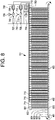
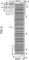
- four sets of liquid discharge members are arranged such that the carrier oil and encapsulation oil are bulk dispensed into a row of vessels, followed by the dispensing of the polynucleotide samples and then the PCR reagents required for a particular marker detection ( see, e.g., Figure 9 ).
- non-miscible oils While one or two non-miscible oils, polynucleotide sample volume, primers, probes, and PCR reagents can be dispensed into the vessels in any order, it is preferable to dispense the one or more non-miscible oils into the vessels prior to dispensing the polynucleotides to prevent contamination of the vessels.
- multiple sets of discharge members are configured to match the number of vessels in a row, e.g., liquid discharge members configured with 12 pipetting tips at a spacing equal to that of the vessels in each row.
- Suitable vessels used to contain the aqueous oil matrices include, but are not limited to, 96-well microtiter plates with workable volumes ranging from about 15 ⁇ L to about 100 ⁇ L and diameters of about 3 mm to about 6 mm, 384-well microtiter plates with volumes ranging from about 2 ⁇ L to about 40 ⁇ L and diameters of about 2 mm to about 4 mm, 384-well or 1536-well Array Tape® with vessel volumes ranging from about 0.5 ⁇ L to about 2 ⁇ L and diameters of about 0.5 mm to about 3 mm, or a dimpled-well belt or chain on a track assembly with vessel volumes ranging from about 1 ⁇ L to about 20 ⁇ L and diameters of about 0.5 mm to about 4 mm (see Figures 4A and 4B ), and the like. It is preferred that the vessels for use herein be transparent and made from plastic or glass.
- reaction-by-reaction light-mediated heating is applied to each vessel and/or directly to each aqueous reaction mix volume to raise the temperature of the aqueous reaction mix volume according to the timing and temperatures required for a particular PCR temperature cycle, it being understood that the term "reaction-by-reaction” refers to the application of electromagnetic radiation (and temperature measurement) to each individual aqueous reaction mix volume and/or aqueous oil matrix as opposed to a system utilizing constant temperature zones or photonic heating of multiple reactions simultaneously by a single light source under single control.
- PCR amplification of double stranded DNA requires an initial denaturing of the DNA ("hot start") following by multiple cycles of annealing, elongation, and denaturation.
- Suitable temperatures for the denaturation step are in the temperature range from about 90 °C to about 99 °C, e.g., about 90 °C, 91 °C, 92 °C, 93 °C, 94 °C, 95 °C, 96 °C, 97 °C, 98 °C, or 99 °C.
- the denaturation temperature is about 95 °C.
- the temperature is lowered, e.g., via a heat sink or application of cool air, to an annealing temperature optimized for the hybridization of the primers and labeled probes to the target polynucleotide strand.
- the probes are covalently linked to a fluorophore capable of excitation by electromagnetic radiation having a certain spectral wavelength.
- the annealing temperature is typically optimized based upon the length and nucleic acid composition of the primers and/or probes using techniques well known in the art. For instance, the thermal melting point (Tm) can be approximated from the equation of Meinkoth et al., Anal. Biochem.
- Tm 81.5° C + 16.6 (log M) 4-0.41 (%GC)-0.61 (% form)-500/L; where M is the molarity of monovalent cations, % GC is the percentage of guano sine and cytosine nucleotides in the DNA, % form is the percentage of formamide in the hybridization solution, and L is the length of the hybrid in base pairs.
- the Tm is the temperature (under defined ionic strength and pH) at which 50% of a complementary target sequence hybridizes to a perfectly matched probe. Tm is reduced by about 1 ° C for each 1% of mismatching; thus, Tm hybridization conditions can be adjusted to hybridize to sequences of the desired identity. For example, if sequences with ⁇ 90% identity are sought, the Tm can be decreased 10° C.
- stringent conditions are selected to be about 5° C lower than Tm for the specific sequence and its complement at a defined ionic strength and pH.
- Suitable temperatures for the annealing step are in the temperature range from about 50 °C to about 70 °C, e.g., about 50 °C, 51 °C, 52 °C, 53 °C, 54 °C, 55 °C, 56 °C, 57 °C, 58 °C, 59 °C, 60 °C, 61 °C, 62 °C, 63 °C, 64 °C, 65 °C, 66 °C, 67 °C, 68 °C, 69 °C, or 70 °C.
- the annealing temperature is in the range from about 50 °C to about 65 °C.
- the annealing temperature is in the range from about 55 °C to about 65 °C.
- the temperature is raised to allow for elongation of new polynucleotide strands from the hybridized primers.
- Suitable temperatures for the elongation step are in the range from about 65 °C to about 75 °C, e.g., 65 °C, 66 °C, 67 °C, 68 °C, 69 °C, 70 °C, 71 °C, 72 °C, 73 °C, 74 °C, or 75 °C.
- the elongation step is carried out at about 70 °C.
- the systems and methods of the present disclosure comprise a plurality of PCR temperature cycles, ranging from 2 to 60, or more, e.g., 2, 3, 4, 5, 6, 7, 8, 9, 10, 11, 12, 13, 14, 15, 16, 17, 18, 19, 20, 21, 22, 23, 24, 25, 26, 27, 28, 29, 30, 31, 32, 33, 34, 35, 36, 37, 38, 39, 40, 41, 42, 43, 44, 45, 46, 47, 48, 49, 50, 51, 52, 53, 54, 55, 56, 57, 58, 59, 60, or more cycles, wherein each PCR temperature cycle comprises an annealing step, an elongation step, and a denaturation step.
- each aqueous oil matrix is cooled to a temperature range from about 55 °C to about 65 °C, e.g., 55 °C, 56 °C, 57 °C, 58 °C, 59 °C, 60 °C, 61 °C, 62 °C, 63 °C, 64 °C, or 65 °C, prior to beginning the next annealing step.
- the aqueous oil matrices can be cooled by an active or passive cooling mechanism, such as a passive metal heat sink, actively circulating air currents, passively circulating air currents, a Peltier device, a circulating liquid or any combination thereof.
- aqueous reaction mix volumes small enough (e.g., 10 ⁇ L or less) to allow for efficient and direct heating via an electromagnetic radiation source such that only a few seconds are required to achieve the annealing, elongation, and denaturation temperatures for each cycle.
- a PCR cycle requires the application of electromagnetic radiation for a period of 20, 19, 18, 17, 16, 15, 14, 13, 12, 11, 10, 9, 8, 7, 6, 5, 4, 3, 2, 1 seconds or less.
- the radiation heats the aqueous reaction mix volume by heat absorption of the water molecules in the aqueous reaction mix volume or by the heat absorption of heat absorptive pigments, thermochromic dyes, plasmon-excitable materials, or a combination thereof.
- heat absorptive pigments, thermochromic dyes, and/or plasmon-excitable materials may be disposed on the walls of the vessel or dispersed within the vessel and/or within the aqueous reaction mix volume.
- Exemplary electromagnetic radiation sources suitable for use with the present systems and methods include lasers, halogen lamps, laser diodes, and light emitted-diodes.
- the electromagnetic radiation source emits ultraviolet radiation having a spectral wavelength in the range from about 100 nm to about 350 nm. In other embodiments, the electromagnetic radiation source emits visible light having a spectral wavelength in the range from about 380 nm to about 700 nm. In a preferred embodiment, the electromagnetic radiation source emits blue light having a spectral wavelength in the range from about 350 nm to about 500 nm. In a more preferred embodiment, the electromagnetic radiation source emits blue light having a spectral wavelength in the range from about 350 nm to about 450 nm.
- the electromagnetic radiation source emits blue light having a spectral wavelength of about 450 nm. In yet other embodiments, the electromagnetic radiation source emits infrared radiation having a spectral wavelength in the range from about 1,200 nm to about 2,200 nm. In a preferred aspect, the electromagnetic radiation source emits infrared radiation having a spectral wavelength in the range from about 1,450 nm to about 1,600 nm ( e.g., about 1,550 nm). Thus, an electromagnetic radiation source suitable for use in the present systems and methods will have a spectral wavelength ranging from about 100 nm to about 2,200 nm.
- the electromagnetic radiation sources are laser diodes.
- Laser diodes are relatively inexpensive, small, and reliable with a very long service life.
- Solid-state laser diodes suitable for use with the present systems and methods are similar to those found in many common electronic devices such as compact disc and digital versatile disc players or in optical fiber communication.
- the energy output from such a laser diode can be focused on a very small area ( e.g., via a collimating lens), and laser diodes are commercially available in a wide variety of spectral output wavelengths and wattages.
- the energy needed to raise the temperature of a aqueous reaction mix having a very small volume, e.g., approximately 5 ⁇ L, 1 ⁇ L, or less, is very small.
- an electromagnetic radiation source e.g., a laser diode
- a laser diode for emitting infrared radiation having a spectral wavelength in the range from about 1,200 nm to about 2,200 nm to a vessel containing an aqueous oil matrix, wherein a volume of the aqueous reaction mix comprises a polynucleotide sample to be analyzed by PCR genotyping (e.g., for end-stage PCR product detection or real-time PCR product detection).
- the energy output can be concentrated on the aqueous reaction mix volume in the aqueous oil matrix.
- the aqueous reaction mix volume is centered within an aqueous oil matrix, and the spectral wavelength of the infrared radiation is about 1,550 nm.
- a laser diode for emitting the infrared radiation may be positioned above the vessel or below the vessel. It is known in the art that infrared radiation is readily absorbed by water molecules. Therefore, the infrared radiation may be focused directly on the aqueous reaction mix volume wherein heat is readily absorbed by the water molecules within to directly heat the aqueous reaction mix. It is to be understood that the laser diode is placed within close proximity to the vessel at a distance that may vary depending on how the infrared light is focused.
- An exemplary laser diode configured for the emission of infrared radiation will comprise a power source and an optional lens or an optional collimator for adjusting the focus of the infrared beam.
- the laser diode may comprise one or more optical fibers or light pipes for providing an optical pathway for the infrared radiation and allowing for flexibility in positioning of the laser diode in relation to the vessel.
- the laser diode may be placed at a distance of 1, 2, 3, 4, 5, 6, 7, 8, 9, 10, 11, 12, 13, 14, 15, 16, 17, 18, 19, 20, 21, 22, 23, 24, 25, 26, 27, 28, 29, 30 cm, or more from either the top of the vessel or the bottom of the vessel, and the lens or collimator may be used to focus the infrared radiation on the aqueous reaction mix volume.
- the infrared beam will be focused such that the size of the beam is approximately equivalent to the size of the aqueous reaction mix volume.
- the amount of time needed to heat the sample for each PCR cycle can be calculated based on the specific heat of water (i.e., 4.184 J/g°C) and the power output used for the laser and the heat dissipation rate of the materials and vessels. For instance, depending on specific total thermal mass and heat dissipation properties, a 1550 nm laser diode powered by 50 mW may be focused on the aqueous reaction mix having a volume of about 1 ⁇ L. Thus, the temperature of the aqueous reaction mix, can be heated from ambient, or room temperature, to about 60 °C in approximately 1 second, and then to about 70 °C in another 0.8 seconds, and then to about 95 °C in as little as 2 seconds.
- a laser diode can be used to emit infrared radiation to heat the volume of the aqueous reaction mix through one PCR temperature cycle in about 3.3 seconds.
- Each individual PCR temperature cycle can be performed on an aqueous reaction mix volume with one laser diode.
- larger aqueous reaction mix volumes e.g., 5 ⁇ l
- an infrared light-emitting laser diode using a low energy input e.g., about 80 to about 200 mW
- inefficiencies occur in the absorption of infrared light by water and the heat conducted into the surrounding encapsulation fluid and/or carrier fluid and even into the vessel walls.
- the heat being conducted into the oil and glass from the aqueous reaction mix volume may balance the energy being put into the aqueous reaction mix volume by the laser diode and results in inhibition of temperature elevation.
- the encapsulation fluid or carrier fluid the volume of the aqueous reaction mix, and the power output of the laser.
- the volume of the aqueous reaction mix can be reduced by about 2-fold to about 100 fold, or more (e.g., 1,000-fold via an acoustic transfer), the power of the laser diode can be increased to transfer energy into the vessel at a rate greater than the rate of loss, and/or the absorption of available light energy for the conversion to heat can be improved such that heat is conducted to the aqueous reaction mix volume increased rate compared to the rate of heat loss.
- heat absorption is improved using heat absorbing dyes and particles, and/or aqueous oil matrices are used to enable the use of smaller volumes of aqueous reaction mix ( e.g., less than 5 ⁇ L).
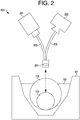
- the electromagnetic radiation source 201 e.g., a laser diode emitting infrared radiation
- the electromagnetic radiation source 201 is positioned at the top of vessel 101. Electromagnetic radiation is carried, or conducted, along an optical path by an optical fiber or light pipe 203 and focused on the aqueous reaction mix volume 104 via a collimator lens 204.
- an electromagnetic radiation source e.g., light-emitting diode (LED)
- LED light-emitting diode
- the aqueous reaction mixture volume comprises a polynucleotide sample to be analyzed by PCR genotyping.
- the aqueous reaction mixture volume is positioned within two non-miscible oils, such as the exemplary aqueous oil matrix depicted in Figure 1 .
- an LED is positioned within optical communication with vessel and emits electromagnetic radiation having a spectral wavelength of about 450 nm (i.e., blue light).
- an LED for emitting the blue light may be positioned above the vessel or at the bottom of the vessel. While water molecules do not readily absorb blue light radiation, the aqueous reaction mix volume can be uniformly heated by the LED light source using plasmon excitable particles in the aqueous reaction mix volume. Plasmon excitable materials that readily absorb blue light can emit heat by a process known in the art as photothermal light-to-heat conversion via photon-electron-phonon coupling.
- Suitable plasmon excitable particles for absorbing blue light radiation include, but are not limited to particles comprising gold, silver, nickel, platinum, or a combination thereof.
- the plasmon excitable material is gold.
- gold in photonic PCR is described in detail in Ho Son et al. (2015).
- selected walls of the vessels may be coated in plasmon excitable material (e.g., gold particles) by electrolysis or vapor-deposition.
- a thin film or layer comprising plasmon excitable material is dispersed in the vessel at or near the bottom of the vessel such that the thin film or layer is within the aqueous oil matrix, but within or underneath the aqueous reaction mix ( see, e.g., Figure 3 ).
- a thin film or layer of gold is placed inside the vessel and at the bottom of the vessel such that the thin film or layer is in intimate contact with the aqueous oil matrix and between the aqueous reaction mixture and the bottom of the vessel.
- a Mylar disk comprising the thin layer of gold is placed in the vessel and at the bottom of the vessel.
- a gold-coated aluminum foil disk is placed in the vessel at the bottom of the vessel.
- the thickness of the thin film or layer of plasmon excitable material is in the range from about 10 nm to about 100 nm, e.g., 10, 11, 12, 13, 14, 15, 16, 17, 18, 19, 20, 21, 22, 23, 24, 25, 26, 27, 28, 29, 30, 31, 32, 33, 34, 35, 36, 37, 38, 39, 40, 41, 42, 43, 44, 45, 46, 47, 48, 49, 50, 51, 52, 53, 54, 55, 56, 57, 58, 59, 60, 61, 62, 63, 64, 65, 66, 67, 68, 69, 70, 71, 72, 73, 74, 75, 76, 77, 78, 79, 80, 81, 82, 83, 84, 85, 86, 87, 88, 89, 91,91, 92, 93,94, 95, 96, 97, 98, 99, or 100
- the thickness of the thin film or layer of plasmon excitable material is in the range from about 50 nm to about 500 nm, e.g., 50 nm, 60 nm, 70 nm, 80 nm, 90 nm, 100 nm, 200 nm, 300 nm, 400 nm, or 500 nm.
- Thicker films or layers of metallic material up to about 1 mm thick or more, can absorb light and convert the light energy to heat, but surface plasmonic resonance is reduced which slows heating.
- the material coated with the then layer of gold may constitute the bottom of the vessel or may be positioned on the bottom of the vessel wall.
- the LED is positioned at the top or the bottom of the vessel and focused ( e.g., by a lens or collimator) to emit blue light radiation on the gold layer for conduction of heat into the aqueous droplet.
- the LED is placed within close proximity to the vessel at a distance that may vary depending on how the blue light is focused.
- An exemplary LED configured for the emission of blue light radiation will comprise a power source and a lens or a collimator for adjusting the focus of the light beam.
- the LED may comprise one or more optical fibers or light pipes for providing an optical pathway for the LED and allowing for flexibility in positioning of the laser in relation to the vessel containing the sample.
- the LED housing has a physical diameter less than the distance between the reaction vessels and is positioned directly beneath the vessel. In such embodiments, the small LED will be linked to the power source using conventional circuitry, and the LED will comprise a collimator to allow for beam focusing.
- the LEDs of the present disclosure may be placed at a distance of 1, 2, 3, 4, 5, 6, 7, 8, 9, 10, 11, 12, 13, 14, 15, 16, 17, 18, 19, 20, 21, 22, 23, 24, 25, 26, 27, 28, 29, 30 mm, or more from either the top of the vessel or the bottom of the vessel, and the optional lens or collimator may be used to focus the light beam on a thin layer of plasmon excitable material, such as gold.
- the blue light bean will be focused on the plasmonic excitable material such that the size of the beam is approximately equivalent to the surface area of the plasmonic excitable material.
- a Mylar disk comprising a thin layer of gold (e.g., between about 10 nm and 0.2 mm thickness) is placed in the vessel, and the blue light radiation emitted from the LED is focused such that the size of the beam is approximately equivalent to the size of the Mylar or aluminum foil disk and thin layer of gold.
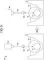
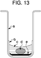
- FIG. 3 Depicted in Figure 3 is an embodiment of the disclosure comprising a electromagnetic radiation source for the emission of visible light (e.g., an LED emitting blue light).
- a electromagnetic radiation source for the emission of visible light e.g., an LED emitting blue light.
- An aqueous oil matrix comprising an aqueous reaction mix volume 304 positioned within an encapsulation oil 303 and a carrier oil 302.
- the electromagnetic radiation source 309 e.g., an LED emitting blue light
- vessel 301 e.g., a transparent plastic vessel.
- a thin layer of plasmonic excitable material 306 is dispersed in vessel 301 such that the plasmonic excitable material is positioned at the bottom of vessel 301 within or in contact with the carrier oil 302, but beneath the encapsulation oil 303 and aqueous reaction mix volume 304.
- the plasmonic excitable material may be gold.
- a passivation layer 305 made from any suitable material used in the art (e.g., plastic, dimethylsiloxane, or silicon dioxide) is disposed over the plasmonic excitable material 306 to prevent the PCR reaction components in the aqueous reaction mix volume 304 from reacting with the plasmonic excitable material 306.
- aqueous oil matrix creates separation between the aqueous reaction mix volume 304 and the plasmonic excitable material 306 and decreases the likelihood that the PCR reaction components will react with the plasmonic excitable material.
- an optional collimator lens 308 enables focusing of the light beam (dotted line) on plasmonic excitable material 306, which then converts the light energy to heat that is uniformly conducted to the aqueous reaction mix volume 304.
- a detector 307 is positioned in optical communication with the top of vessel 301.
- the detector 307 may comprise any suitable detection device for the detection of thermal radiation (e.g., black body infrared radiation) and/or fluorescence emitted from the aqueous reaction mix volume (dotted line), as will be discussed in greater detail elsewhere herein.
- thermal radiation e.g., black body infrared radiation
- fluorescence emitted from the aqueous reaction mix volume dotted line
- the Belt Positioning Device The Belt Positioning Device
- the present systems and methods comprise a positioning device for discretely moving the vessels (e.g., step-by-step as opposed to continuous movement) containing the aqueous oil matrices through the various subsystems and vessel stations of the system.
- the positioning device is a moving belt comprised of a plurality vessels (e.g., wells or dimples), wherein the vessels will contain the assembled aqueous oil matrices.
- the belt may be constructed of flexible plastic, thermoplastic polymers (e.g., polypropylene, polystyrene, or polycarbonate) or other materials similar to that used for ARRAY TAPE®.
- the vessels are stamped into the belt material to form dimples.
- the volume of each well ranges from 0.2 ⁇ L to about 20 ⁇ L with a diameter of each vessel ranging from about 0.5 mm to about 4 mm depending on the desired design parameters.
- the belt, and the vessels within the belt may be fabricated from one continuous material or may be fabricated in small segments, wherein each segment comprises a configured set of reaction vessels, and where the segments are attached, or chained together, by any suitable technique in the art, to constitute the belt.
- the segments can be interchanged or replaced as needed to simplify creation of optimal configurations for various vessels volumes and/or to support maintenance and/or repair.
- the belts will be joined end-to-end to form a loop structure and will operate via a motorized track communicatively connected to a mechanical and electronic control system, which will actuate the belt to move the vessels in discrete steps from the assembly subsystem through each of the heating positions, temperature monitoring positions, PCR product detection positions.
- the belt will move the vessels to a waste disposal subsystem after completion of the PCR amplification and PCR detection cycles.
- Each actuation of the belt is followed by a stop (e.g., step-by-step movement) to position each row of vessels at the appropriate vessel station.
- a stop e.g., step-by-step movement
- vessel stations comprise: 1) assembly of the aqueous oil matrices via the assembly subsystem; 2) a heating position via the photonic heating subsystem; 3) a temperature monitoring position via the temperature monitoring subsystem; 4) a PCR product detection position via the fluorescence detection subsystem; and 5) optionally, waste disposal via the waste disposal subsystem.
- vessel stations comprise: 1) assembly of the aqueous oil matrices via the assembly subsystem; 2) a heating position via the photonic heating subsystem, a temperature monitoring position via the temperature monitoring subsystem, and a PCR product detection position via the fluorescence detection subsystem; and 3) optionally, waste disposal via the waste disposal subsystem.
- vessel stations comprise: 1) assembly of the aqueous oil matrices via the assembly subsystem; 2) a heating position via the photonic heating subsystem; 3) a temperature monitoring position via the temperature monitoring subsystem and a PCR product detection position via the fluorescence detection subsystem; and 4) optionally, waste disposal via the waste disposal subsystem.
- vessel stations comprise: 1) assembly of the aqueous oil matrices via the assembly subsystem; 2) a heating position via the photonic heating subsystem and a temperature monitoring position via the temperature monitoring subsystem; 3) a PCR product detection position via the fluorescence detection subsystem; and 4) optionally, waste disposal via the waste disposal subsystem.
- addition vessel stations may be included in the system, such as vessel stations comprising a cooling position via an active or passive heat sink and a hot start position or positions via photonic heating.
- FIGS. 4A and 4B Depicted in Figures 4A and 4B are exemplary embodiments of a belt design suitable for use with the present system and methods.
- a belt 402 is disposed on drive gears 401 at each end.
- the mechanical and electronic control system will cause rotation of the drive gears 401 (indicated by arrow) to enable the belt to move each row of vessels in discrete steps through each vessel station.
- the belt 402 comprises a plurality of vessels 404 suitable for containing an aqueous oil matrix. Any variation of vessels spacing can be utilized.
- vessel spacing can be from about 1 mm to about 10 mm or more, e.g., 1 mm, 1.5 mm, 2 mm, 2.5 mm, 3 mm, 3.5 mm, 4 mm, 4.5 mm, 5 mm, 5.5 mm, 6 mm, 6.5 mm, 7 mm, 7.5 mm, 8 mm, 8.5 mm, 9 mm, 9.5 mm, 10 mm, or more.
- vessel spacing is in a range from about 8 mm to about 10 mm.
- spacing of the vessels is about 9 mm to fit with international standards for well spacing in microtiter plates and standard tip spacing in multi-tip pipettors.
- the belt will comprise rows of vessels, wherein each row will include any number of vessels ranging from 2 to 100 vessels, or more in each row. More preferably, the number of vessels in each row is 2, 3, 4, 5, 6, 7, 8, 19, 10, 11, 13, 12, 14, 15, 16, 17, 18, 19, 20, 21, 22, 23, 24, 25, 26, 27, 28, 29, 30, or more vessels.
- Shown in Figure 4B is the most preferred embodiment, wherein each row of vessels in belt 402 comprises 12 vessels.
- the size and shape of each vessel can be designed based on the encapsulation oil volume such that the encapsulation oil is substantially stationary when positioned within the carrier oil thus maintaining the aqueous reaction mix volume substantially centered in the well.
- a flexible belt 402 is disposed on drive gears 401 at each end.
- the mechanical and electronic control system will cause rotation of the drive gears 401 in the direction of the arrow to enable the belt to move each row of vessels in discrete steps through each vessel station.
- the vessels of the belt may be coated ( e.g., via electrolysis, vapor deposition, or emulsion painting) with a plasmonic excitable material, such as gold.
- a plasmonic excitable material such as gold.
- the plasmonic excitable material is inserted into each vessel as a coated disk of Mylar, aluminum foil, or other suitable thin material carrier.
- FIG 4A Also shown in Figure 4A is a plurality of passive heat sink metals 403 for cooling each row of vessels when at a vessel station in close proximity to a passive heat sink metal 403.
- the present systems and methods provide for direct heating and temperature monitoring of each vessel enabling the optimization and regulation of the PCR thermocycling conditions for each vessel.
- the present systems and methods can be programmed to run a plurality of different PCR thermocycling conditions to amplify and detect PCR products using a plurality of different polynucleotide samples with different primers, probes, and PCR reagents. Since the temperatures of the aqueous oil matrices in the vessels must be monitored to enable the present system to regulate the amount of energy to provide from the lasers to change the temperature of the vessel to the values desired for efficient PCR thermocycling, provided herein is a temperature monitoring subsystem.
- the temperature monitoring subsystem collects temperature data from each of the vessels during, simultaneously with, or after each PCR temperature cycle that can be used to aid in quality control. In other embodiments, the temperature monitoring subsystem collects temperature data from each of the vessels during each PCR temperature cycle that can be used to determine a baseline temperature for optimization of the next heating cycle or, alternatively, for normalization of temperature-sensitive fluorophores. Aqueous oil matrices (or aqueous reaction mix volumes) that do not change temperature as expected can indicate incorrect volume dispensing of the assembly subsystem or instrument malfunction. In certain embodiments, temperature measurement information is available every 15 seconds or less as the system is running. In addition, some embodiments of the system incorporate software functionality that alert laboratory staff of any temperature inaccuracies.
- Such functionality can include, but is not limited to, alerts based on temperatures out of set limits, failures to detect expected temperature changes within expected time intervals during photonic heating, or temperature changes that are erratic or vary in unexpected ways.
- Software providing such functionality can be custom-coded or may utilize algorithms publicly or commercially available.
- the position of the vessel containing the aqueous oil matrix where temperature or thermal information is collected and monitored is sometimes referred to herein as a "temperature monitoring position.”
- the temperature monitoring subsystem comprises a plurality of thermal detection devices each of which corresponds to a vessel containing an aqueous oil matrix.
- Suitable thermal detection devices are known in the art and include, but are not limited to, direct contact thermistors and/or thermocouples, non-contact thermal imagers, discrete thermopile sensors, thermopile arrays, other infrared sensors, or optical fibers and/or fiber optic arrays in optical communication with a non-contact thermal infrared sensing device.
- the temperature monitoring subsystem comprises a plurality of thermal detection devices, e.g., thermistors or thermocouples, disposed within each of the vessels containing an aqueous oil matrix and configured to collect and send temperature data to the temperature monitoring subsystem via conventional circuitry or wireless communication.
- the temperature monitoring subsystem comprises a plurality of thermal detection devices (e.g., optical fibers or light pipes) in optical communication with a thermal infrared sensing device (e.g., thermal imaging camera or infrared sensor).
- each thermal detection device is in optical communication with each vessel containing an aqueous oil matrix when the vessel is in a temperature monitoring position, and wherein each thermal detection device is configured to provide a measuring signal that is dependent on the intensity of black-body infrared radiation emitted by the aqueous oil matrix as an indication of temperature. Further, each thermal detection device may be configured to provide a thermal radiation path from the volume of the aqueous oil matrix (or the aqueous reaction mix volume) to the thermal infrared sensing device for the collection of temperature data.
- the thermal detection devices are optical fibers or light pipes that are not dispersed in the vessels and do not make physical contact with the aqueous oil matrices.
- the thermal detection devices e.g., one or more optical fibers, detect emitted black body infrared radiation from each aqueous oil matrix (or aqueous reaction mix volume), which is then carried via a fiber optic array to a thermal infrared sensing device, such as an infrared-sensitive camera or thermal imager.
- the thermal infrared sensing device measures the intensity of black body infrared radiation signal from each vessel and converts the intensity to temperature.
- the black body radiation from each aqueous oil matrix is directly detected by an infrared-sensitive camera or thermal imager positioned in proximity to the reaction volumes such that the infrared radiation of one or more reaction volumes is simultaneously captured in a single image of the camera or imager.
- a temperature measurement is taken from each vessel containing an aqueous oil matrix when that vessel is in a temperature monitoring position.
- the temperature monitoring position is the same position as the heating position.
- the thermal detection devices are positioned at the same location ( e.g., the same vessel station) as the electromagnetic radiation sources.
- the electromagnetic radiation sources and thermal detection devices can be positioned in several suitable arrangements.
- the electromagnetic radiation sources and the thermal detection devices can be positioned in proximity to the top of the vessels containing the aqueous oil matrices.
- FIG. 2 Depicted in Figure 2 is an embodiment of the present system where an electromagnetic radiation source 201 (e.g., laser diode or LED) and a detector 202 are positioned above vessel 101.
- the detector 202 may be a thermal infrared sensing device and/or a fluorescence detection device. In some embodiments, detector 202 is a combination of the thermal infrared sensing device and the fluorescence detection subsystem.
- Electromagnetic radiation is emitted from the electromagnetic radiation source 201 to the aqueous reaction mix volume 104 (dotted line) positioned within an aqueous oil matrix comprising an encapsulation oil 103 and a carrier oil 102.
- electromagnetic radiation such as infrared radiation
- electromagnetic radiation is carried, or conducted, along an optical path by an optical fiber or light pipe 203 and focused on the aqueous reaction mix volume 104 via a collimator lens 204.
- aqueous reaction mix volume 104 emits black body infrared radiation (dotted line) that is carried to a thermal infrared sensing device of detector 202 by an optical fiber 205.
- the black body infrared radiation is carried to a thermal infrared sensing device of detector 202 via a bundle of optical fibers and/or an optical fiber array.
- electromagnetic radiation source 201 emits infrared radiation
- electromagnetic radiation source 201 and the thermal infrared sensing device of detector 202 cannot operate simultaneously without interference of thermal detection.
- the electromagnetic radiation source 201 must be turned off while the thermal infrared sensing device of detector 202 is turned on.
- Near real-time temperature measurements can still be accomplished if the system is programmed to "flicker" the electromagnetic radiation source 104 and the thermal imaging device of detector 202. Flickering is well known in the art and comprises a rapid, alternating series of short infrared radiation pulses followed by thermal detection.
- the temperature monitoring position is the same position, e.g., vessel station, as the heating position, and the electromagnetic radiation sources are positioned in proximity to the bottom of the vessel containing the aqueous oil matrices while the thermal detection devices are positioned at the top of the vessel containing the aqueous oil matrices.
- Shown in Figure 3 is a configuration where the electromagnetic radiation source 309 is positioned at the bottom of the vessel, and detector 307 is positioned at the top of the vessel.
- detector 307 may be, e.g., an infrared sensor or an optical fiber(s) for providing a thermal radiation path to a thermal infrared imaging device.
- the temperature monitoring position is at a different position, e.g., vessel station, than the heating position.
- Shown in Figure 5 is a configuration where an electromagnetic radiation source 501 is positioned at the top of vessel 101 when in the heating position.
- the vessel 101 is moved to a second vessel location where detector 502 is positioned at the top of the vessel when in the temperature monitoring position.
- the detector 502 can be a thermal infrared sensing device or a fluorescence detection device.
- detector 502 is a combination of a thermal infrared sensing device and the fluorescence detection subsystem.
- Electromagnetic radiation is emitted from the electromagnetic radiation source 501 to the aqueous reaction mix volume 104 (dotted line) positioned within an aqueous oil matrix comprising an encapsulation oil 103 and a carrier oil 102.
- electromagnetic radiation such as infrared radiation
- vessel 101 is moved by a positioning device, e.g., a motorized belt-on-a track device, to the next vessel station where a thermal infrared sensing device of detector 502 measures the emission of black body infrared radiation from aqueous reaction mix volume 104.
- the black body infrared radiation is carried to the thermal infrared sensing of detector 502 via an optical fiber and/or fiber optic array 505. In other embodiments, the black body infrared radiation is carried to the thermal infrared sensing of detector 502 via a bundle of optical fibers and/or a fiber optic array. In yet other embodiments the black body infrared radiation is detected directly by a non-contact infrared sensor or thermal imaging camera.
- the temperature measurements cannot be collected simultaneously with application of photonic heating, but can be used to determine the baseline temperature of the aqueous oil matrices in between PCR cycles such that the system can adjust the amount of energy output needed to heat the aqueous reaction mix volume for the next PCR cycle, e.g., a microcontroller.
- the temperature measurements can be used to normalize the fluorescence emission of temperature-sensitive fluorophores.
- the present systems and methods comprise a fluorescence detection subsystem configured to emit and detect fluorescence light for the detection of one or more fluorophore-labeled probes that have hybridized to a target polynucleotide sample.
- the fluorescence detection subsystem comprises one or more fluorescence excitation light sources, one or more fluorescence emission light sensing devices, and a plurality of one or more optical members configured to provide an optical path for conducting fluorescence excitation light to each vessel in the PCR product detection position and for conducting fluorescence emission light from each vessel to the fluorescence light emission sensing device(s).
- the optical path, or optical connection, between the fluorescence excitation light source(s) and the corresponding vessel may comprise any one of a variety of optical arrangements and can include a variety of optics of conventional construction.
- fluorescence emission light sensing devices suitable for use with the present systems and methods include, e.g., charge-coupled device (CCD) cameras, complimentary metal-oxide semiconductor (CMOS) cameras, photomultipliers, and sensor arrays.
- CCD charge-coupled device
- CMOS complimentary metal-oxide semiconductor
- photomultipliers photomultipliers
- any suitable fluorescence excitation light source can be used in the fluorescence detection subsystem and include, but are not limited, to LEDs, laser diodes, argon ion lasers, xenon lamps, and the like.
- the fluorescence excitation light source can be configured to emit fluorescence light having a suitable spectral wavelength in the range from about 300 nm to about 1,200 nm depending on the particular fluorophore or fluorophores used in the PCR reaction. Fluorophores and other fluorescence-excitable species having a particular excitation/emission wavelength are well known and commercially available. Exemplary fluorophores and fluorescent dyes suitable for use with the present system and methods are provided in Table 1. Table 1. Non-limiting list of commonly used fluorophores.
- Suitable optics for guiding light can include at least one of the following: an optical fiber(s), a fiber optic array, or light pipes; a lens, including a condensing lens, an objected lens, a Fresnel lens, an imaging lens, a positive lens, a field lens, or a collimator lens; a reflector, such as a mirror or a beam splitter; an excitation filter, such as a dichroic filter; and an emissions filter.
- optical fiber(s) can include at least one of the following: an optical fiber(s), a fiber optic array, or light pipes; a lens, including a condensing lens, an objected lens, a Fresnel lens, an imaging lens, a positive lens, a field lens, or a collimator lens; a reflector, such as a mirror or a beam splitter; an excitation filter, such as a dichroic filter; and an emissions filter.
- These optics and other useful optics are well known in the art and
- the flexibility of using optical fibers allows for many different arrangements of the present system.
- the fluorescence detection subsystem provided herein is configured for continuous or periodic monitoring and measuring of reaction-generated fluorescence during and/or after the PCR temperature cycles performed on each vessel containing an aqueous oil matrix.
- the position of the vessel containing the aqueous oil matrix where PCR product detection is monitored and measured by the PCR product detection subsystem is sometimes referred to herein as a "PCR product detection position.”
- the fluorescence detection occurs at the end of the PCR temperature cycles. In a preferred embodiment, the PCR product detection occurs in real-time, wherein the fluorescence is measured after each PCR temperature cycle. In some embodiments, the fluorescence detection subsystem is configured to detect fluorescence from each individual aqueous reaction mix after each individual PCR temperature cycle, and the data collected from the PCR measurements can be analyzed and scored by automated software algorithms via a laboratory information management system (LIMS).
- LIMS laboratory information management system
- the aqueous reaction mix comprises two distinct nucleic acid probes conjugated to or covalently linked to a fluorophore capable of excitation by fluorescence excitation light having a particular spectral wavelength or range of spectral wavelengths, wherein each nucleic acid probe is designed to specifically hybridize to a target nucleic acid sequence (e.g., polymorphism) of a polynucleotide sample.
- a target nucleic acid sequence e.g., polymorphism
- a first nucleic acid probe comprises a first fluorophore capable of excitation by fluorescence excitation light having a first spectral wavelength
- a second nucleic acid probe comprises a second fluorophore capable of excitation by fluorescence excitation light having a second spectral wavelength.
- the first spectral wavelength is a different wavelength than the second spectral wavelength such that the presence of the first nucleic acid probe can be distinguished from the presence of the second nucleic acid probe.
- each optical member comprises one or more optical fibers capable of providing an optical path for fluorescence excitation light and/or fluorescence emission light between the fluorescence detection subsystem and the aqueous reaction mix volume in each of the vessels when the vessel is in the PCR product detection position.
- each optical member comprises a bundle of optical fibers.
- each optical member comprises a single optical fiber capable of carrying all light between each vessel and the fluorescence detection subsystem. For instance, fluorescence excitation and fluorescence emission light could be stacked over a single array of fiber optics through sequential excitation filters and emission filters (e.g., dichroic filter blocks) with diagonal optical feeds to direct the fluorescence emissions to the fluorescence emission light sensing devices.
- each optical member comprises a separate fiber optic array for each fluorescence light wavelength used in the system.
- each fiber optic array for fluorescence detection contains an individual optical fiber in optical communication with each vessel containing an aqueous oil matrix when the vessel is in the PCR product detection position, wherein each individual optical fiber comprises one end in close proximity to a vessel containing an aqueous oil matrix and the other end in an ordered tightly bundled array with a flat face presented to a fluorescence excitation light source and a fluorescence light emission sensing device.
- An excitation filter e.g., dichroic filter similar to those used on epi-fluorescence microscopes
- an emission filter may be placed in the optical path between the array face and the fluorescence emission light sensing device.
- a dichotic filter or filter cube comprises both the excitation filter and the emission filter and is placed in the optical path between the fiber optic array face and the fluorescence excitation light source and the fluorescence emission light sensing device ( see, e.g., Figure 8 ).
- the fluorescence emission light sensing device is configured to collect an image at the fiber optic array face and measure the signal intensity of each individual fiber.
- the fluorescence detection subsystem may employ a fluorescence excitation light source that is provided by a laser (e.g., an argon-ion laser) to emit fluorescence excitation light having a spectral wavelength ranging from about 350 nm to about 1,100 nm.
- a plurality of optical members such as optical fibers, are used in which each optical fiber is in optical communication with the laser and inserted through a lens positioned over each vessel containing an aqueous oil matrix when in the PCR product detection position to provide an optical path for the conduction of light to and from the vessel.
- the fluorescence excitation light is directed through the optical fibers to excite the fluorophores in the aqueous reaction mix volume.
- Emissions from the aqueous reaction mix volume are sent back through the optical fibers to a fluorescence emission light sensing device.
- fluorescence detection systems are commercially available, such as the ABI PRISM® detection systems (Applied Biosystems).
- the laser is capable of emitting fluorescence excitation light having one or more spectral wavelengths for the detection of one or more labeled probes conjugated or covalently linked to different fluorophores having different excitation/emission wavelengths.
- separate lasers can be used, each emitting a fluorescence excitation light having a different spectral wavelength.
- a single optical fiber corresponding to each vessel can be used to direct all fluorescence light to and from each vessel when in the PCR product detection position (i.e., excitation and emission fluorescence light is stacked over the single fiber).
- sequential excitation light filters e.g., dichroic filter blocks
- diagonal optical feeds can be used to direct the fluorescence emissions to the fluorescence emission light sensing devices.
- separate optical fibers which can be configured as an fiber optic array, are used for providing an optical path for each fluorescence excitation wavelength used for detection.
- the fluorescence detection subsystem may employ a plurality of LEDs or laser diodes for the emission of fluorescence excitation light. Since the footprint of an LED or laser diode is very small, multiple LEDs or laser diodes of different wavelengths could be integrated into a single package or multiple packaged LEDs/laser diodes placed very closely to excite a single vessel containing an aqueous oil matrix when in the PCR product detection position. In such an embodiment, the LEDs/laser diodes can be positioned at one or more vessel stations directly beneath the vessels when the vessels are in the PCR product detection position. Fluorescence detection systems having such a configuration are also found in the patent literature, e.g., U.S. Patent No. 7,122,799 .
- fluorescence excitation light generated by the LEDs/laser diodes can be directed to the vessels by a plurality of optical fibers, wherein each optical fiber is inserted through a lens (e.g., collimator lens) and positioned at the top or bottom of a vessel when the vessel is in the PCR detection position.
- a lens e.g., collimator lens
- a fluorescence detection subsystem may employ a plurality of LEDs or laser diodes for the generation of fluorescence excitation light, wherein one or more fiber optic arrays for fluorescence detection provide an optical path for the excitation and emission fluorescence light.
- the fluorescence detection subsystem is configured to monitor and measure fluorescence from two nucleic acid probes, each of which is covalently linked to a different fluorophore (e.g., VIC or FAM).
- the excitation and emission fluorescence light suitable for excitation of both nucleic acid probes is stacked over a single array of fibers through sequential excitation/emission filters, e.g., dichroic filter blocks, with diagonal optical fees for the fluorescence emission light sensing devices, e.g., emission imaging sensors or CCD cameras.
- sequential excitation/emission filters e.g., dichroic filter blocks
- diagonal optical fees for the fluorescence emission light sensing devices e.g., emission imaging sensors or CCD cameras.
- two fiber optic arrays are used, in which each fiber optic array provides an optical path for excitation and emission fluorescence light suitable for excitation of one of the nucleic acid probes ( see, e.g., Figure 8 ).
- each fiber optic array comprises a plurality of optical fibers, wherein each optical fiber is in optical communication with a vessel containing an aqueous oil matrix when the vessel is in the PCR product detection position.
- One end of each individual optical fiber may be positioned over the top of the vessel or the bottom of the vessel depending on the particular design and space requirements.
- the other end of each individual optical fiber is disposed within an ordered tightly bundled fiber optic array with a flat face in optical communication with both an fluorescence excitation light source (e.g., an LED or laser diode) and an fluorescence emission sensing device (e.g., a monochrome CCD camera).
- an fluorescence excitation light source e.g., an LED or laser diode
- an fluorescence emission sensing device e.g., a monochrome CCD camera
- An excitation and/or emission filter such as a dichroic filter, may be placed within the optical path and in optical communication with the fiber optic array face and the appropriate fluorescence excitation light source and/or fluorescence emission sensing device (see, e.g., Figure 8 ).
- the fluorescence emission sensing device collects the image of the fiber optic array face and measures the intensity of the signal from each individual fiber by examining regions of interest in the image.
- a detection subsystem comprises both a thermal infrared imaging device and the fluorescence detection subsystem.
- a single optical fiber for carrying all light, i.e., blackbody infrared radiation and fluorescence excitation and emission light between all detectors (i.e., the thermal infrared sensing device and the one or more fluorescence emission light detectors) and a vessel containing an aqueous oil matrix.
- detectors i.e., the thermal infrared sensing device and the one or more fluorescence emission light detectors
- separate fiber optic arrays are used for thermal detection and each fluorescence excitation light wavelength.
- a fluorescence measurement is taken from each vessel containing an aqueous oil matrix when that vessel is in a PCR product detection position.
- the PCR product detection position is the same locations, e.g., same vessel stations, as the heating position and the temperature monitoring position.
- the electromagnetic radiation sources and the thermal detection devices can be positioned at and/or in optical communication with the top of the vessels containing the aqueous oil matrices.
- an electromagnetic radiation source 201 e.g ., laser diode or LED
- a detector 202 are positioned at and/or in optical communication with the top of vessel 101.
- detector 202 is a combination of the thermal infrared sensing device and the fluorescence detection subsystem. Electromagnetic radiation is emitted from the electromagnetic radiation source 201 to the aqueous reaction mix volume 104 (dotted line) positioned within an aqueous oil matrix comprising an encapsulation oil 103 and a carrier oil 102. In this embodiment, electromagnetic radiation, such as infrared radiation, is carried along an optical path by an optical fiber or light pipe 203 and focused on the aqueous reaction mix volume 104 via a collimator lens 204.
- aqueous reaction mix volume 104 emits black body infrared radiation (dotted line) that is carrier to the thermal infrared sensing device of detector 202 by an optical fiber(s) 205.
- both the electromagnetic radiation source 201 and the thermal infrared sensing device of detector 202 are shut off to allow for fluorescence detection. Fluorescence excitation light is carried from the fluorescence detection subsystem of detector 202 along optical fiber(s) 205 and is focused by lens 204 on the aqueous reaction mix volume 104.
- a fluorophore covalently linked to a nucleic acid probe Upon absorption of the fluorescence light having the appropriate wavelength, a fluorophore covalently linked to a nucleic acid probe emits fluorescence that is collected and conducted by optical fiber(s) 205 to a fluorescence emission light sensing device of detector 202.
- fluorescence excitation light having two different wavelengths is carried between the fluorescence detection subsystem and the aqueous reaction volume 104 by a single optical fiber 205. In other embodiments, fluorescence excitation light having two different wavelengths is carried between the fluorescence detection subsystem and the aqueous reaction volume 104 via a bundle of optical fibers and/or one or two optical fiber array(s).
- the PCR product detection position is at a different location, e.g., vessel station, than the heating position.
- Shown in Figure 5 is a configuration where an electromagnetic radiation source 501 is positioned at the top of vessel 101 when in the heating position.
- the vessel 101 is moved by the positioning device to the next vessel station where detector 502 is positioned at the top of the vessel 101 when in the PCR detection position.
- Fluorescence excitation light is carried from the fluorescence detection subsystem of detector 502 along optical fiber(s) 505 and is focused by lens 506 on the aqueous reaction mix volume 104.
- fluorescence excitation light having two different wavelengths is carried between the fluorescence detection subsystem and the aqueous reaction volume 104 by a single optical fiber 505. In other embodiments, fluorescence excitation light having two different wavelengths is carried between the fluorescence detection subsystem and the aqueous reaction volume 104 via a bundle of optical fibers and/or one or two optical fiber array(s).
- the present systems and methods comprise a combination of subsystems for providing reaction-by-reaction, light-driven photonic heating; reaction-by-reaction temperature monitoring; and fluorescence detection of PCR products for PCR amplification and product detection.
- the present systems and methods additionally comprise a positioning device configured to move a collection of aqueous oil matrices in discrete steps through a plurality of vessels stations, wherein the vessel stations may include one or more of the subsystems.
- the positioning device comprises a flexible belt, such as belt 402 depicted in Figures 4A and 4B .
- the belt 402 comprises a flexible material (e.g., a thermoplastic polymer) forming a loop structure around two or more drive gears 401, and wherein a plurality of vessels 404 are embedded in the belt 402.
- Drive gears 401 rotate and cause the belt 402 to move the vessels 404 from vessel station to vessel station.
- the mechanical, electronic, and software systems that control the movement of the drive gear are described in detail elsewhere herein.
- a photonic heating subsystem 600 comprising a plurality of electromagnetic radiation sources 602 and a belt 402 as a positioning device for moving the vessels 404 from vessel station to vessel station.
- the number of electromagnetic radiation sources 602 can vary depending on spacing and design parameters.
- the size of the electromagnetic radiation sources and the associated circuitry and/or cabling will determining the particular spatial configuration.
- the photonic heating subsystem 600 includes 504 independent electromagnetic radiation sources 602 and a belt 402 wherein the vessels 404 are arranged in rows of 12 vessels per row at 9 mm spacing to fit with international standards for well spacing.
- the electromagnetic radiation sources 602 are stacked vertically on 42 modules 601 positioned to a side of belt 402, with 12 electromagnetic radiation 602 sources in each vertical stack (see Figures 6A and 6B ).
- photonic heating subsystem 600 is further configured such that the arrangement of the electromagnetic radiation sources 602 correspond with the configuration of the vessels 404 on belt 402.
- each electromagnetic radiation source 602 is in optical communication with an optical fiber or light pipe 602, with each optical fiber or light pipe 603 providing an optical path for guiding the emitted electromagnetic radiation to a corresponding vessel 404 when that vessel is in the heating position. This configuration facilitates easy connections to circuitry and other cabling.
- each optical fiber or light pipe 603 that is proximal to the corresponding vessel 404 terminates in a lens configured to focus the beam of electromagnetic radiation on the aqueous reaction mix volume or plasmonic excitable material depending on the particular wavelength of the electromagnetic radiation being used. For instance, when using infrared radiation, the beam is focused on the aqueous reaction mix volume and absorbed by the water molecules to heat the aqueous reaction mix. Alternatively, if visible light, such as blue light, violet light, or ultraviolet light is used, the beam is focused on a plasmonic excitable material, such as a gold layered Mylar or aluminum foil disk, to convert the light energy to heat energy.
- a plasmonic excitable material such as a gold layered Mylar or aluminum foil disk
- each module 601 is positioned adjacent to every other row of vessels 404 to accommodate a cooling and fluorescence detection position between each PCR temperature cycle.
- the vessels 404 are cooled by an active or passive cooling member 403, such as a passive heat sink metal, positioned under the top side of the loop of belt 402.
- each electromagnetic radiation source 602 operates at a fixed and constant wattage output, wherein each electromagnetic radiation source 602 can be activated for a specific period of time, under computer programmable control, to provide the desired amount of energy needed to heat each aqueous reaction mix through a PCR temperature cycle.
- the wattage output of the electromagnetic radiation sources 602 can be varied.
- Figure 6A depicts a front view of the photonic heating subsystem 600 and belt 402, wherein the electromagnetic radiation sources 602 are stacked vertically on module 601, with 12 electromagnetic radiation sources 602 in each vertical stack.
- Each optical fiber and light pipe 603 extend from the corresponding electromagnetic radiation source 602 to the top of the corresponding vessel 404 of belt 402.
- FIGC depicts a top view of the photonic heating subsystem 600 and belt 402.
- Each electromagnetic radiation source 602 is electronically connected to electronics bay 604.
- vessels 404 are coated with a plasmonic excitable material such as gold to maximize conversion of light (e.g., ultraviolet, violet, or blue light) to heat.
- a gold layered Mylar or aluminum foil disk is disposed within each vessel 404 to maximize conversion of light (e.g., ultraviolet, violet, or blue light) to heat.
- FIG. 7 depicts a side view illustrating an embodiment of the PCR amplification and product detection system.
- fiber optic arrays 701 translate light between between the vessels of the belt 402 and a set of light detectors 708, which include fluorescence emission light detectors and a thermal infrared sensing device.
- the use of fiber optic arrays 701 allows optical communication between the detectors and vessels spread out over a wide area.
- the use of fiber optic arrays 701 provide for the translation of light between vessels spread over a 100 mm by 900 mm area and a small ordered set of fiber end faces occupying an area of only 10 mm by 15 mm, or smaller.
- Fiber optic arrays are commercially available and are often used to condense optical signals from microtiter plate wells for efficient imaging by CCD cameras, such as described in FiberGuide Industries, "White Paper: 2D Arrays" (available on the FiberGuide Industries website).
- each module 601 is positioned adjacent to every other row of vessels on the belt 402 to accommodate a temperature monitoring position and/or a cooling and fluorescence detection position between each PCR temperature cycle.
- the vessels are cooled by an active or passive cooling member 403, such as a passive heat sink metal, positioned under the top side of the loop of the belt 402.
- the fiber optic arrays 701 provide an optical path to the light detectors 708 from each vessel of the belt 402 when that vessel is in the PCR product detection position and the temperature monitoring position.
- the lights detectors 708 include two CCD cameras 706, 710 as the fluorescence emission light detectors and a thermal imager 704 as the thermal infrared sensing device.
- a thermal imager 704 as the thermal infrared sensing device.
- the fiber optic arrays 701 include three separate fiber optic arrays 714, 715, 716, each in a tightly ordered bundle at one end connected to fiber optic array plates 713, 712, 709, respectively. Two of the fiber optic arrays 715, 716 conduct fluorescence excitation/emission light for fluorescence detection, while the third fiber optic array 714 conducts black body infrared radiation for temperature monitoring. Further, each fiber optic array 715, 716 for fluorescence detection in this exemplary embodiment comprises 480 individual optical fibers with one end of each fiber positioned over a vessel when that vessel is in the PCR product detection position.
- the fiber optic array 714 for temperature monitoring in this exemplary embodiment comprises 504 individual optical fibers with one end of each optical fiber positioned over a vessel when that vessel is a temperature monitoring position.
- the first temperature monitoring position provides a baseline temperature reading of a row of vessels (indicated as "I") before the heating process begins.
- the next two temperature monitoring positions provide temperature readings during the hot start process.
- the remaining temperature monitoring positions are at the same vessel stations as the passive heat sink metals 403 and the PCR detection positions.
- the excitation light source 707 emits fluorescence excitation light through a dichroic filter cube 702 to a fiber optic array plate 709 optically connected to an ordered tightly bundled array configured to provide an optical path along the fiber optic array 716 to each vessel when that vessel is in the PCR product detection position. Further, fluorescence emission light from the aqueous reaction mix volume is conducted from the vessel along the fiber optic array 716 to the fiber optic array plate 709.
- the fiber optic array plate 709 produces an image array on its face by condensing the optical signals of the fluorescence emission light, and the CCD camera 706 collects the image and measures the intensity of the signal of each individual fiber in the image.
- the excitation light source 705 emits fluorescence excitation light through a dichroic filter cube 711 to a fiber optic array plate 712 optically connected to an ordered tightly bundled array configured to provide an optical path along the fiber optic array 715 to each vessel when that vessel is in the PCR product detection position.
- fluorescence emission light from the aqueous reaction mix volume is conducted from the vessel along the fiber optic array 715 to the fiber optic array plate 712.
- the fiber optic array plate 712 produces an image array on its face by condensing the optical signals of the fluorescence emission light, and the CCD camera 710 collects the image and measures the intensity of the signal of each individual fiber in the image.
- black body infrared radiation emitted from each aqueous oil matrix at the initiation stage "I", following each "hot start” "D", and during each PCR product detection step is conducted along the fiber optic array 714 to a fiber optic plate 713.
- the infrared image on the face of the fiber optic plate 713 is measured by the thermal imager 704, which measures the intensity of the signal for each vessel and converts the intensity to temperature.
- an infrared radiation filter 703 is placed between the face of the fiber optic plate 713 and the thermal imager 704.
- the PCR amplification and product detection system additionally comprises an assembly subsystem configured for programmable and automated assembly of collections of aqueous oil matrices.
- an assembly subsystem is provided that comprises liquid discharge members 801, 802, 803, 804.
- the liquid discharge member 801 is a 12-tip bulk dispenser configured for dispensing carrier oil
- the liquid discharge member 802 is a 12-tip bulk dispenser configured for dispensing encapsulation oil
- the liquid discharge member 803 is an automated pipettor ( e.g., a fixed pipetting head with 12 tips) configured for dispensing an aqueous volume comprising polynucleotide samples
- the liquid discharge member 804 is an automated pipettor (e.g., a single tip, non-contact pipetting head) configured for dispensing an aqueous volume comprising PCR reagents, primers, and/or probes.
- FIG. 9 Depicted in Figure 9 is a side view of an embodiment of the PCR amplification and product detection system.
- a system control causes the belt 402 to move a row of 12 vessels into an assembly position.
- the belt 402 advances one step (9 mm) when all operations occurring simultaneous at all vessel stations on belt 402 are complete.
- the PCR temperature cycle with the longest duration is approximately 15 seconds. Therefore, the processes occurring have no more than approximately 15 seconds to complete each process before the belt is programmed to move to the next step.
- a 12-tip bulk pipettor 801 aspirates carrier oil from a carrier oil input and dispenses the carrier oil into the row of vessels.
- the belt 402 moves the row of vessels to the next assembly position where a 12-tip bulk pipettor 802 aspirates encapsulation oil from an encapsulation oil input and dispenses the encapsulation oil into the row of vessels.
- the belt 402 moves the row of vessels to the next assembly position, where fixed pipetting heads 803 aspirate an aqueous volume that contains the appropriate polynucleotide sample from, e.g., an input plate comprising a bar code.
- the assembly station may comprise a bar code reader configured to read the bar code and access, e.g., LIMS software to identify the polynucleotide sample and to determine the appropriate primers and probes for use with each particular polynucleotide sample.
- the control system then causes the fixed pipetting heads 803 to dispense the polynucleotide sample into as many vessels as needed to accommodate the number of primer/probe reactions to be run. In some cases, the number of runs will require multiple rows of vessels.
- the fixed pipetting heads 803 have approximately 15 seconds, or less, depending on the timing of the PCR temperature cycles to perform the dispensing step for each row. Furthermore, the fixed pipetting heads 803 may be configured for either automated or manual tip changes to prevent contamination or, alternatively, the fixed pipetting heads 803 may be configured for either automated tip washing.
- the belt 402 then moves the row of vessels to the final assembly position, where a single, tip, non-contacting pipetting head 804 aspirates an aqueous volume containing the appropriate PCR reaction mix, primers, and probes in an amount sufficient for all of the polynucleotide samples to be tested with that particular PCR reaction mix, primers, and probes.
- the assembly substation then causes the single, tip, non-contacting pipetting head 804 to dispense the PCR reaction mix, primers, and probes into the row of vessels containing the appropriate polynucleotide sample.
- the information necessary to identify the appropriate PCR reaction mix, primers, and probes for a particular PCR genotyping reaction can be provided from a LIMS.
- loaded lists of simple queries could provide the assembly software program with the needed information from the LIMS.
- Similar hardware and software configurations suitable for use with the present system are known in the art. As with all other processes occurring at a given vessel station, the PCR reaction mix, primers, probes dispensing step has approximately 15 seconds to be completed.
- the belt 402 moves the row to the next vessel station where, optionally, an initial temperature measurement "I" can be taken to provide this information to the system control software for determining the amount of output energy required for hot start denaturation of the polynucleotide samples in each aqueous reaction mix.
- an optical fiber from the fiber optic array 714 is positioned above each well and conducts black body infrared radiation emitted by each aqueous oil matrix at this vessel station to the fiber optic array plate 713, which condenses the optical signals for imaging by the thermal imager 704.
- the thermal imager 704 converts the signal intensity to temperature information that is used by the control system software to adjust the pulse duration of the electromagnetic radiation sources 602 when the vessels are moved forward to the first hot start heating position "D".
- two hot start positions are each followed by a temperature monitoring position.
- the control system software causes the belt 402 to move the row of vessels to the next vessel station, which is the first hot start heating position "D".
- each electromagnetic radiation source 602 is a laser diode emitting infrared radiation.
- laser diodes 602 emit infrared radiation through light pipes 603, wherein the end of each light pipe 603 is positioned at the top of each vessel in the row to apply infrared radiation to the aqueous reaction mix volume contained therein.
- each aqueous reaction mix volume is raised to about 90 °C to about 99 °C, most preferably to about 95 °C, to denature the polynucleotide samples in each aqueous reaction mix volume.
- the control software causes the belt to move the row of vessels to the next vessel station, which is a temperature monitoring position.
- An additional hot start heating position "D" is included in case the needed hot start denaturation requires more than 15 seconds.
- the belt 404 moves the row of vessels to the next vessel station, which is a cooling position and a temperature monitoring position.
- the cooling position comprises passive heat sink metal 403 positioned proximately underneath the top side of belt 404 as shown in Figure 9 .
- the passive heat sink metal blocks 403 come into contact with the bottom of the vessels, heat is transferred from the aqueous oil matrix through the vessels and into the heat sink metal blocks 403 to cool the aqueous oil matrices in the row.
- the temperature of the aqueous oil matrices is decreased to about 60 °C.
- the temperature of each aqueous oil matrix is measured via the thermal imager 704.
- the control system causes the belt 402 to move the row of vessels to the next vessel station to begin PCR temperature cycling.
- the laser diodes 602 emit infrared radiation to the aqueous reaction mix volume in each vessel in the row, thereby raising the temperature of the aqueous reaction mix volume.
- the control system software enables marker specific PCR conditions by causing the laser diodes to emit appropriate infrared radiation energy and pulse duration to raise the temperature of the aqueous reaction mix volume to the appropriate annealing temperature and elongation temperature.
- the control system causes the belt 402 to move the row of vessels into the cooling position, PCR product detection position, and temperature monitoring position at the next vessel station.
- Fluorescence excitation light having spectral wavelengths suitable for excitation of the fluorophores present in the PCR reaction mix are emitted from fluorescence excitation light sources 705, 707 through the fiber optic arrays 715, 716 and to the aqueous reaction mix of each vessel in the row.
- Fluorescence emission light from the vessels is conducted back through the fiber optic arrays 715, 716 to the CCD cameras 710, 706, which convert the optical signal intensity to raw fluorescence signals for processing by the control system software.
- an optical fiber from the fiber optic array 714 is positioned above each well and conducts black body infrared radiation emitted by each aqueous oil matrix at this vessel station to the fiber optic array plate 713, which condenses the optical signals for imaging by the thermal imager 704.
- the thermal imager 704 converts the signal intensity to temperature information that is used by the control system software to adjust the pulse duration of the electromagnetic radiation sources when the vessels are moved forward to the heating position. This process is repeated up to 40 or more PCR temperature cycles.
- the dichroic filter cubes 702, 711 and the infrared emission filter 703 enable the temperature measurements and the fluorescence measurements to occur simultaneously by preventing crosstalk by the different spectral wavelengths.
- the temperature measurements and the fluorescence measurements are performed sequentially within the available timeframe. Temperature monitoring after the heating step is useful for providing the control system software with temperature information necessary to determine the appropriate energy output required for the next heating step. In some embodiments comprising a temperature monitoring step after the photonic heating step, dynamic temperature feedback during the heating steps is not possible due to rapid heat dissipation.
- the aqueous reaction mix volumes dissipate heat rapidly and exhibit a decrease in temperature by about 20 oC per second when the heating source is removed. Therefore, in some embodiments, the heating positions comprise insulation to decrease heat loss.
- temperature monitoring at the PCR product detection position is used by the control system software to normalize the raw fluorescence data, because it is known in the art that fluorescence light having certain spectral wavelengths can be affected by temperature.
- embodiments comprising a cooling mechanism at the PCR product detection position lower the temperature of the aqueous reaction mix to allow all fluorescence measurements to be taken at approximately the same temperature.
- dynamic temperature feedback during the photonic heating steps can be accomplished by placing the laser diodes and the thermal detectors at the same position.
- thermal imaging cannot be performed simultaneously with the heating if the electromagnetic radiation sources emit significant infrared radiation in the same infrared band used to heat the aqueous reaction mix volumes unless a "flickering" process is used (i.e., rapidly alternating flashing of the infrared heating source with detection sensing of black-body infrared emission).
- a thermocouple or a thermistor is used in place of thermal imaging, which enables temperature monitoring to be performed simultaneously with infrared irradiation enabling dynamic temperature feedback during the photonic heating.
- a waste dispose subsystem comprising aspirators 901, 903, a bulk dispenser 902, an oil separator 905, and a ultraviolet lamp 904.
- the aqueous oil matrices may be removed from the vessels and discarded.
- the control system causes the belt 402 to move the row of vessels from the vessel station comprising the final PCR product detection position to the aspirator 901.
- the aspirator 901 is a 12-position pipetting head. The aspirator 901 aspirates the entire aqueous oil matrix from each vessel in the row and passes the aqueous oil matrix to waste.
- the aqueous oil matrix is passed through a tubing system that would eliminate the need to move the aspirators 901 to the waste location.
- the control system then causes the belt 402 to move the row of vessels to the bulk dispenser 902, which dispenses clean oil or water into each vessel of the row.
- the control system causes the belt 402 to move the row of vessels to the aspirators 903, which aspirate the oil or water from each vessel in the row.
- an embodiment may comprise an oil separator 905 in which the carrier and encapsulation oil are drawn off and reused in the assembly subsystem.
- control system causes belt 402 to move the wells to the underside of the belt loop, wherein an ultraviolet lamp 904 emits ultraviolet radiation to destroy any remaining polynucleotides in the vessels to prevent polynucleotide contamination of subsequent PCR reactions.
- FIG 10 Depicted in Figure 10 is a preferred arrangement of the photonic heating position, temperature monitoring position, and PCR product detection position of the PCR amplification and product detection system.
- the belt, the assembly subsystem, and the waste disposal subsystem are arranged as shown in Figure 9 .
- the system comprises heating positions and temperature monitoring positions at the same vessel stations in an alternating configuration with vessel stations comprising the PCR product detection positions (and cooling positions).
- the belt moves a row of vessels into a heating position, wherein the electromagnetic radiation sources are positioned beneath the vessels.
- the electromagnetic radiation sources e.g ., LEDs
- the LEDs are positioned at the bottom of each vessel when the vessel is in a heating position, wherein the LEDs emit electromagnetic radiation having a spectral wavelength in the range from about 100 nm to about 500 nm ( i.e. , ultraviolet, violet, and blue light wavelengths) ( see , e.g., Figure 3 ).
- LEDs emit blue light.
- the electromagnetic radiation is focused via a collimating lens on a gold-coated Mylar film disposed between the bottom of the vessel and the encapsulation oil. The light energy is converted to heat energy (as described elsewhere herein) and raises the temperature of the aqueous reaction mix volume.
- simultaneous temperature monitoring is performed via a thermal imaging sensor in optical communication with the aqueous oil matrix.
- an optical fiber is positioned at the top of each vessels when that vessel is in a temperature monitoring position and conducts black-body infrared radiation emitted from the aqueous oil matrix to the thermal imaging sensor ( see , e.g., Figure 3 ).
- an infrared emission filter is placed in the optical path of the black-body infrared radiation and positioned between the thermal imaging sensor and a flat face of a fiber optic plate ( see , e.g., Figure 9 ).
- each PCR temperature cycle is completed in about ten seconds or less.
- the control system causes the belt to move the row of vessels to the next vessel station, which comprises a PCR product detection position.
- fluorescence excitation light having two different spectral wavelengths is generated by the fluorescence excitation light sources of the fluorescence excitation and emission detector and carried, e.g., by one or more optical fibers positioned above each vessel when that vessel is in the PCR product detection position, and transmitted to the aqueous reaction mix volume (shown by dotted arrows).
- fluorophores in the aqueous reaction mix volume emit fluorescence emission light that is carried back to the fluorescence excitation and emission detector by, e.g., the one or more optical fibers (shown by dotted arrows).
- the intensity of the fluorescence emission light is then measured by the fluorescence emission light detector (e.g., CCD camera) of the fluorescence excitation and emission detector.
- the optical path of each fluorescence excitation light comprises a fluorescence excitation light source, a dichroic filter cube, a fiber optic array plate, a CCD camera, and a fiber optic array ( see, e.g., Figure 9 ).
- each fluorescence excitation light is comprised of only a light source (LED or laser) and the fluorescence emission detection is comprised only of an emission filter and a CCD or CMOS camera.
- a passive heat sink may be disposed under the top side of the belt and positioned beneath each vessel when in the PCR detection position ( see, e.g., Figure 9 ). After the PCR product detection step is completed, the control system causes the belt to move the row of vessels to the next vessel station where the process is repeated for a predetermined number of PCR temperature cycles ranging from 1 to 40.
- FIG. 11 is a functional block diagram of a preferred embodiment comprising control functions for a complete beginning-to-end single device embodiment (such as the moving belt embodiments shown in Figures 9 and 10 ).
- the present system comprises assembling the reactions in well-plates off-line and/or manually moving an array of vessels to a device configured such that PCR heating and fluorescence detection is accomplished without moving the vessels ( i.e., without the need for a moving belt or other automated positioning device).
- a device configured such that PCR heating and fluorescence detection is accomplished without moving the vessels (i.e., without the need for a moving belt or other automated positioning device).
- Such embodiments are made possible by co-locating heating and fluorescence detection components on common light paths associated with each vessel. In such a case, reaction assembly and/or vessel positioning is not needed. Heating and detection operations on the device would occur sequentially, rather than simultaneously at separate locations.
- PCR cycle heating followed, sequentially, by fluorescence detection complications imposed by possible interference of fluorescence detection by the heating light source and the rapidly changing temperatures are eliminated.
- continuous loading, processing, and unloading is not possible and throughput is more limited.
- FIG. 11 Depicted in Figure 11 is a functional block diagram of a preferred embodiment comprising control functions for a complete beginning-to-end single device embodiment.
- the system comprises a Main Instrument Process Flow Controller (PLC or electronic microcontroller) which is programmed to provide functions to initiate and control each action involved in the process flow of a "run" occurring on the instrument.
- a "run” is defined herein as operations on a set of reactions assembled, processed, and monitored for PCR product fluorescence where the PCR amplification and product detection system runs autonomously without any significant instructional input during the process flow and the PCR amplification and product detection system is not shutdown or reset during the process flow for any bulk loading, unloading, or maintenance operations.
- reaction assembly and PCR parameter information needed by the system to support a run is pre-defined and communicated to the system before the run begins.
- An embodiment that uses such a control system is the microtiter plate-based system.
- information needed to begin assembly and processing of available samples and reactions is communicated to PCR amplification and product detection system to begin operations, and additional information is subsequently communicated to the PCR amplification and product detection system to augment its instructions and support continued assembly and processing of additional samples that are provided such that the system instrumentation does not completely stop at any time during the run and a process flow is maintained.
- individual sub-systems can have their own electronic microcontrollers or may be controlled by sub-routines, multiple processors, and electronic modules of the Main Instrument Process Flow Controller. In either case, the subsystems perform their individual functions in cooperation and coordination such that timing of operations assures proper assembly and processing of all reactions. For instance, the exact time required to perform a particular PCR thermocycling heating and cooling operation for any given reaction assembly volume is not known in advance and is determined, dynamically, through feedback temperature monitoring of the particular reaction assembly volume during the heating process. Therefore, the Main Instrument Process Flow Controller collects and compiles feedback signal status information for every vessel undergoing processing and prevents the next processing step from occurring for any vessels until the previous step is completed for all vessels.
- Fluorescence detection is not initiated until thermocycling heating is completed.
- wells are not advanced down the belt by the Vessel Array Position Motor Controllers until it is confirmed by the Main Instrument Process Flow Controller that reaction assembly is complete and/or fluorescence detection readings are complete for all wells.
- the Main Instrument Process Flow Controller informs the Vessel Array Positioning Process Controllers to relay motor positioning information to the Vessel Array Position Motor Controllers to cause the positioning device (e.g., moving belt) to move the vessels to the next vessel station. Therefore, the particular reaction volumes that require the longest time for a given processing step determine the rate of progress of the entire system.
- the Main Instrument Process Flow Controller passes commands and needed information, such as sample identification and volume information, to the reaction assembly Pipetting Process Controllers on where to get samples, reagents, and oils.
- the Pipetting Process Controllers send motor position information to the Pipetting Position Motor Controllers and Pipetting Aspiration/Dispensing Motor Controllers which move liquids to reaction vessels and inform the Main Instrument Process Flow Controller of the arrangement of reactions that have been assembled in the vessels.
- the Main Instrument Process Flow Controller can, alternatively, command a particular pre-defined arrangement of reactions, but the system works more efficiently if the Pipetting Process Controllers inform the Main Instrument Process Flow Controller of the arrangement of the reactions it can create quickly.
- the Main Instrument Process Flow Controller can then record the arrangement in a Local Storage Database such that when fluorescence data is collected, the system can determine what particular reaction mix generated what fluorescence.
- the photonic heating subsystem employs proportional-integral-derivative (PID) controller hardware or software in combination with custom-developed heating control rule sets to determine the energy needed to drive the light sources. PID parameters and rules are tuned to provide the fastest possible heating without significant overshoot of set point desired temperatures.
- the Main Instrument Process Flow Controller sends heating profile info, including what temperature set points to achieve and how long to hold the reaction volume at each temperature, to the Heating Controllers and triggers the Heating Controllers to send temperature set point information to the PID Heating Power Regulator.
- the PID Heating Power Regulator transmits the power-level information to the Heating Light Source Power Supplies, which provide the appropriate energy output to the Heating Light Sources ( i.e ., the electromagnetic radiation sources).
- the Heating Light Sources then emit electromagnetic radiation to the vessels.
- present system comprises a plurality of Temperature Sensors (i.e ., thermal detection devices, such as optical fibers in optical communication with a thermal infrared sensing device, thermistors, or thermocouples), which, in some embodiments, provide real-time PCR temperature cycle information.
- Temperature Sensors i.e ., thermal detection devices, such as optical fibers in optical communication with a thermal infrared sensing device, thermistors, or thermocouples
- Individual electronic and software sub-systems reduce the load on some main instrument controllers, especially if the Main Instrument Process Flow Controller processor speed is limited. For instance, heating occurs very fast in small volume reactions. In order to accurately and quickly control the heating process, temperature feedback values are provided approximately every 100 to 200 milliseconds. By employing a separate heating control processor system, the processor is not involved with non-heating control tasks and can handle the quick feedback and control turnaround time required to prevent potential overheating.
- a temperature feedback and light source control subsystem wherein the voltage, current, or infrared image information generated by the Temperature Sensors is sent to a Temperature Sensors Signal Processor that provides feedback temperature information to the PID Heating Power Regulator, which, in response thereto, sends the updated power-level information to the Heating Light Source Power Supplies to adjust the energy output for the Heating Light Sources.
- the PID Heating Power Regulator transmits this information to the Heating Controllers.
- the Heating Controllers will command the PID Heating Power Regulator to provide additional output energy to the Heating Light Sources to raise the temperature of the reaction to the next temperature set point, or, if the PCR temperature cycle is complete, the Heating Controller will command the PID Heating Power Regulator to terminate the energy output thereby turning off the Heating Light Sources.
- the Heating Controllers inform the Main Instrument Process Flow Controller, e.g ., by data communication protocols or by digital line states, that the reaction is complete and awaits further instructions.
- the Fluorescence Detection Controllers provide for functionality to turn on and off Fluorescence Excitation Light Sources when initiated by command from the Main Instrument Process Flow Controller. Likewise, initiation of emission light detection by the Fluorescence Emission Detectors is managed by the fluorescence detection subsystem. As shown in Figure 11 , the Main Instrument Process Flow Controller triggers the Fluorescence Detection Controllers that activate the appropriate Fluorescence Excitation Power Supplies resulting in the emission of fluorescence excitation light from one or more Fluorescence Excitation Light Sources. As described elsewhere herein, the fluorescence excitation light may be conducted to each vessel containing an aqueous oil matrix when that vessel is in the PCR product detection position.
- the fluorophores in the aqueous reaction mix volume respond to the fluorescence excitation light having the appropriate spectral wavelength and emit fluorescence emission light that is carried to a Fluorescence Emission Light Detector.
- the Fluorescence Emission Light Detector sends raw signal information to the Fluorescence Signal Processors, which collect, process, and report the data as relative fluorescence units to the Fluorescence Data Logger.
- the Fluorescence Data Logger passes the relative fluorescence unit information to a Local Storage Database and/or a Genetic Analysis Processor configured to run PCR data analysis software, which determines the genetic allele call to report based on the fluorescence data and information provided by the sample and reaction assembly plan information.
- fluorescence data is collected after each PCR temperature cycle.
- the quality and characteristics of the PCR reactions are such that the PCR data analysis software program informs the Main Instrument Process Flow Controller that a reliable genetic call has been made based on already available information, and the Main Instrument Process Flow Controller can then instruct the Heating Controllers and the Fluorescence Detection Controllers to terminate subsequent processing of the particular aqueous reaction mix volume corresponding to the genetic call data. This additional feedback control saves energy and time.
- the system employs an LCD or video image display to provide status information about the instrument (i.e ., the Instrument LCD Status Display ).
- a Manual Control Interface which allow functions, such as manually starting, pausing, or aborting instrument operations.
- a PC-Based User Interface which can be a separate PC-based application or web-site user interface. Such an interface would allow multiple users the ability to send information to an instrument to setup and begin a run or to load additional reactions into a run that has already begun.
- LIMS Laboratory Information Management Services
- the present system comprises a LIMS program. Shown in Figure 11 are external systems that include a LIMS Data Exchange Services communicatively connected to the LIMS Database and the Local Storage Database and configured to send "run schedule" and plan information to the PC-Based User Interface and "run components" plan information to the Main Instrument Process Flow Controller.
- a gold metal film is needed on the bottom of the reaction well ( Figure 13 ).
- vapor-deposited or electro-plated gold applied directly to the bottom of the well, could be used.
- vapor-deposition and electro-plating processes are inconvenient and impractical for most prototype testing.
- An alternative is to employ gold-coated foil or film disks (e in Figure 13 ) inserted into the bottom of the wells. These disks are punched from commercially available sheet stock of gold-coated Mylar film or gold-coated aluminum foil. Most early prototype testing was performed with gold-coated Mylar film. However, it was found that the Mylar could melt, shrink, or lose its gold coating under certain circumstances.
- two oils can be used to support the aqueous droplet, a silicone encapsulation oil and a perfluorocarbon carrier oil, and this has certain advantages for centering and contamination control.
- a silicone encapsulation oil and a perfluorocarbon carrier oil
- this has certain advantages for centering and contamination control.
- Observations made with a small video camera positioned to the side of a single well container showed that employing some perfluorocarbon oils caused the entire volume of liquid to churn, roil, and split into smaller droplets during rapid heating and cooling. Removing the perfluorocarbon oil and only using a silicone oil (c in Figure 13 ) eliminated this churning.
- hydrophobic coating Without the hydrophobic coating, the aqueous droplets could sometimes stick to the walls of the well which proved detrimental to IR thermal imaging and fluorescence detection and allowed for potential cross-contamination issues if the well is used again for subsequent PCR reactions.
- the super-hydrophobic coating is fairly durable and the well can be used multiple times after one treatment supporting several PCR reactions. Replacing the perfluorocarbon oil with a hydrophobic coating simplifies assembly of reaction volumes, reduces costs, and eliminates potentially hazardous perfluorocarbon waste liquids. While HydroFoeTM is currently used in the prototype systems, there are many other commercially available hydrophobic treatment coatings that would work equally well.
- the selected LEDs could be positioned very close to the bottoms of the wells in the thin-walled vacuum-formed containers ( Figure 14 ) such that most of the light emitted by the LEDs would intersect the gold metal layer in the bottom of the wells. This makes these selected LEDs energy efficient and eliminate the need for a focusing lens.
- the Luxeon Rebel ES 1W 700mA royal blue LEDs worked well if the dome is removed from the LED.
- the Luxeon Z Series ES 700mA LEDs also worked well and are "naked die” LED devices without a protective dome. Removing the dome allows the die to be positioned very close (within 1 millimeter) to the bottom of the vacuum-formed well, improving energy transfer efficiency.
- These LEDs are available as surface-mount devices on tiny pads with contacts allowing them to be easily mounted to a printed circuit board.
- LED Not all input electrical energy is converted to light. A significant amount of heat is generated by an LED. To maintain stability and prolong the life of the LED, the LED may be mounted on a heatsink to allow this heat to be dissipated. In prototype systems fans are positioned to carry this heat away from the LEDs and the wells above the LEDs. Additional fans are positioned to provide an airflow across the bottoms to the wells. These fans are powered on and off automatically by microcontroller software to promote more rapid cooling of the wells when desired.
- an LED driver system has been assembled that provides pulse-width-modulation (PWM) power control of each LED over a single I2C bus from a microcontroller.
- the LED driver system employs a series of PCA9685 modules, available from multiple electronics component sources. Each PCA9685 module can provide 12-bit PWM signals for up to 16 addressable LEDs. The modules contain their own internal clock eliminating the need to continuously refresh the PWM settings.
- the PCA9685 modules can be assembled in a series allowing for several hundred LEDS to be controlled on one I2C bus by a single microcontroller. 6 modules are required to drive 96 LEDs.
- the PWM signal output for each LED from a PCA9685 is routed to a RapidLED Meanwell LDD-700H power driver mounted on a RapidLED LDD-H-4 quad driver board (Rapid LED).
- An LDD-700H is required for each LED.
- Each driver board is connected to a power supply and has connections for each LED output.
- Figure 15 shows the basic arrangement of components needed to drive the LEDs. Only 32 LEDs are shown in the diagram but an assembly was designed for testing that drives 96 LEDs. This design is easily extended for an even larger number of LEDs and is a simple, inexpensive, and flexible way to drive multiple LEDs in prototype systems. Custom-designed, similar functionality, LED control circuits are also possible.
- thermocouples can be inserted into each reaction to provide this feedback temperature information.
- 0.1 mm (0.005 inch) thermocouples (Omega Engineering Inc.) were inserted into individual wells.
- the preferred method of temperature monitoring for most embodiments is the use of non-contact IR sensors. Tests of multiple non-contact IR sensors have been performed.
- Both thermal imaging devices can be interfaced to a microcontroller or computer and can report temperatures from images of observed objects. By positioning these imaging systems above an array of reaction volumes, temperatures can be monitored while light-mediated heating is occurring. In prototype systems the pixel with the highest reported temperature corresponding to a well location was used as the temperature of the well. The temperatures reported are surface temperatures and can be a few degrees less than the temperatures reported simultaneously by thermocouples embedded closer to the gold layer. However, it has been possible to calibrate and compensate for these temperature differences as long as container sizes, configurations, and liquid volumes are maintained constant.
- the typical prototype system test PCR reaction mix is a two probe (bi-allelic) TaqmanTM PCR reaction employing fluorescent FAM and VIC probes. Some reactions also contain an unbound ROX dye used to assess volumes and concentrations of reaction components. A full spectral excitation and emission scan of these PCR reactions showed narrow excitation and emission windows where minimal emission crosstalk between the 2 probe dyes occurred.
- the optimal FAM excitation window was 475 - 500nm with an optimal emission window between 510 - 525nm.
- the VIC fluorescence optimal excitation window was 525 - 535nm with an optimal emission window of 555 - 565nm.
- Excitation and emission filters and excitation light sources were engineered. For devices where only one well is observed, occupying a very small area, numerous light sources and narrow-band optical filters are possible. However, for fluorescence excitation, with illumination of a relatively large area occupied by an array of wells of PCR reaction liquids, an intense and uniform excitation light is needed. Available LED light sources have a very wide spectral output and must be heavily filtered to provide the needed narrow bandwidths needed to support clean separation of FAM and VIC fluorescence emissions. Standard narrow bandpass interference filters can be positioned over LEDs to provide the desired spectral window but the angle of incidence of light hitting an interference filter must be precisely controlled to eliminate undesirable spectral shifts.
- lasers have provided a more workable solution.
- Relatively safe, laser-line devices can project an intense line of light across several PCR wells simultaneously. By nature, the bandwidth of light output from a laser is very narrow. This laser line can be rapidly moved to cover additional wells or the wells can be moved under the laser line to capture fluorescence from multiple rows of wells. Two lasers, one for each desired excitation wavelength can sequentially irradiate all of the reaction volumes and still only take a few seconds.
- Another alternative is to use a galvo-head mirror scanner to deflect a laser point beam sequentially to each of the desired well locations.
- Such devices are commonly used in projecting laser patterns for shows and large audience displays.
- An inexpensive galvo-head mirror scanner can move to over 20 thousand points per second.
- fluorescence light emitted by the FAM and VIC probes can be sequentially detected by a camera that can integrate over the time required to scan a desired number of wells.
- a single camera with a suitable 2 wavelength bandpass filter can be employed or two cameras, each with a less expensive single wavelength narrow bandpass filter can be used.
- Figure 17 illustrates the observed fluorescence from 16 reaction wells after 40 cycles of PCR extracted from a single (200msec exposure) image captured by a ToupTek E3CMOS camera.
- the fluorescence emission light was filtered through a 565nm +/- 5nm narrow bandpass interference filter before entering the camera lens.
- the wells were illuminated by an inexpensive 20mW 532nm laser line (Laserlands, Inc.) to provide the VIC excitation light.
- the collection of 16 samples were a variety of genotypes with homozygous VIC, heterozygous VIC, and VIC negative samples. This variation in genotypes contribute to the variation in height of the peaks.
- VIC fluorescence is demonstrated here since it is more difficult to cleanly measure VIC fluorescence than FAM fluorescence in typical PCR reactions.
- Pixel intensity information was extracted from the acquired image using publically available ImageJ image analysis software (imageJ.nih.gov).
- a set of reaction wells could be moved from a location where heating is performed to an adjacent chamber where the cameras can measure fluorescence.
- the fluorescence detection camera(s) can be positioned next to an IR imaging camera or discrete IR sensors over the same location where wells are heated.
- the 450nm 1W LEDs used to currently provide heating light energy in prototype systems produce a very bright and wide spectral output that swamps out fluorescence detection even with the best emission blocking filters available. Therefore, in these prototype device embodiments the heating light can't be on while fluorescence measurements are being made.
- Two TAQMAN® probes and custom-designed primer pairs forming a bi-allelic interrogation of a DNA target loci were tested with a light-mediated temperature-cycling in an aqueous oil matrix.
- the probes and primers were combined with typical TAQMAN® PCR enzymes and reagents in sealed wells and were run through as many as 40 PCR temperature cycles in a water bath thermocycler. After thermocycling, the PCR products were then measured in a commercial fluorescence reader at emission wavelengths for the FAM and VIC dyes that are associated with the two probes for the particular locus alleles. Elevated FAM and/or VIC fluorescence indicates the presence of amplified PCR products for the DNA alleles for which the probes and primers were designed.
- Sample 1 was known to produce a PCR product for the selected FAM probe.
- Sample 2 was known to produce a PCR product for the selected VIC probe.
- Sample 3 was known to produce a PCR product for both the FAM and VIC probes for the selected specific DNA locus.
- a 384-well, clear flat bottom, plate was prepared with the inside bottom of the wells coated with a thin layer of gold emulsion paint.
- a 0.1 mm (0.005 inch) thermocouple was inserted and positioned in the painted well such that the thermocouple bead was located approximately 0.5mm above the gold paint.
- Aqueous oil matrix PCR reactions were assembled for each of the samples and for a no template control (no DNA added to the reaction) in the prepared wells.
- Each aqueous oil matrix was composed of 2 ⁇ l of an aqueous PCR reaction mix, identical in composition to production genotyping process, in 4 ⁇ l of a silicone encapsulation oil in 4 ⁇ l of a perfluorocarbon carrier oil.
- the aqueous oil matrix reactions in the 384 well plate were positioned over a 200 mW 405 nm laser diode focused to irradiate an area of the gold paint approximately 1.5 mm in diameter.
- An UPC microcontroller such as those described in depth on the chicken website, and regulated power supply were employed to drive the light source such that the light could be flashed on and off as many as 500 times per second with pulse width modulation of the power dependent on the temperature sensed by the thermocouple in the well.
- the microcontroller was programmed to provide two seconds at an achieved temperature of 62 oC, followed by five seconds at an achieved temperature of 72 oC, followed by two seconds at an achieved temperature of 95 oC.
- the microcontroller was programmed to repeat this temperature profile 40 times to accomplish the PCR amplification.
- the temperature profile data from the first ten PCR temperature cycles is provided in Figure 12 .
- the plate was moved to a commercial fluorescence plate reader where FAM and VIC fluorescence was measured for each reaction well. Elevated fluorescence was observed for both FAM and VIC probes for samples as expected.
- a requirement of a PCR amplification system is a source of DNA samples that can be incorporated into the PCR reactions. It has been observed that sufficient quantities of DNA-containing organic material can be found on or in various substrates that have come into contact with various plants or plant parts. Liquid from swabs taken of plant surfaces, small volumes of culture media, or liquids rinsed over various plant parts can contain significant amounts of DNA. Such collected DNA-containing material provides a means of non-destructive DNA sampling of plants.
- This "shed" DNA-containing material can sometimes be used directly, without further purification, as a PCR DNA source if it is exposed to a "heat shock” to release, unravel, and/or de-compartmentalize the DNA contained within the liquid and/or denature or destroy enzymes and other materials that are detrimental to PCR amplification.
- a single very rapid heating and cooling treatment can make the DNA available and suitable for PCR. Two or more rapid heating and cooling cycles could potentially enhance this effect for some plant sources.
- a single 3 microliter volume of aqueous liquid from media surrounding a plant embryo or cultured plant tissue can contain enough DNA for many PCR reactions.
- heat shock is used to obtain DNA from shed material in an apparatus of the invention using the same heat source used in subsequent PCR amplification steps as described above.
- a separate position or location employing a photonic heating apparatus is used to rapidly heat small quantities of liquid containing this shed plant material.
- raising the temperature of the liquid from room temperature to 90 to 98 degrees C. and immediately lowering it again to room temperature provides the needed heat shock.
- This process can be further enhanced in some embodiments by lowering the temperature of the liquid to sub-zero temperatures (-20 degrees C. is frequently used) by using Peltier cooling or immersion in a cold bath before the heating treatment.
- This process can be further enhanced by incorporating a gentle agitation or vibration of the liquid during or after the heat shock.
- This agitation mixes the liquid uniformly and/or enhances release of the DNA.
- a heating (and optional cooling) apparatus could simplify setup of PCR reactions in handheld or portable devices and/or could be used to speed up a heat shock treatment of single or multiple DNA samples while also reducing energy costs.
- DNA may be obtained by incubating plant material with an enzyme; the enzyme may be VISCOZYME® L, a multi-enzyme complex containing a wide range of carbohydrases, including arabanase, cellulase, ⁇ -glucanase, hemicellulase, and xylanase. (See the Sigma Aldrich product catalog).
- VISCOZYME® L a multi-enzyme complex containing a wide range of carbohydrases, including arabanase, cellulase, ⁇ -glucanase, hemicellulase, and xylanase.
- VISCOZYME® L a multi-enzyme complex containing a wide range of carbohydrases, including arabanase, cellulase, ⁇ -glucanase, hemicellulase, and xylanase.
- a heat shock could be used to prepare the released DNA for PCR
Landscapes
- Chemical & Material Sciences (AREA)
- Health & Medical Sciences (AREA)
- Life Sciences & Earth Sciences (AREA)
- General Health & Medical Sciences (AREA)
- Chemical Kinetics & Catalysis (AREA)
- Biochemistry (AREA)
- Immunology (AREA)
- Analytical Chemistry (AREA)
- Physics & Mathematics (AREA)
- Organic Chemistry (AREA)
- Pathology (AREA)
- General Physics & Mathematics (AREA)
- Wood Science & Technology (AREA)
- Zoology (AREA)
- Engineering & Computer Science (AREA)
- Molecular Biology (AREA)
- Proteomics, Peptides & Aminoacids (AREA)
- Clinical Laboratory Science (AREA)
- Nuclear Medicine, Radiotherapy & Molecular Imaging (AREA)
- Microbiology (AREA)
- Biotechnology (AREA)
- Bioinformatics & Cheminformatics (AREA)
- General Engineering & Computer Science (AREA)
- Genetics & Genomics (AREA)
- Hematology (AREA)
- Biophysics (AREA)
- Optics & Photonics (AREA)
- Measuring Or Testing Involving Enzymes Or Micro-Organisms (AREA)
- Investigating, Analyzing Materials By Fluorescence Or Luminescence (AREA)
- Peptides Or Proteins (AREA)
- Dispersion Chemistry (AREA)
Applications Claiming Priority (2)
| Application Number | Priority Date | Filing Date | Title |
|---|---|---|---|
| US201662306432P | 2016-03-10 | 2016-03-10 | |
| PCT/US2017/021359 WO2017156126A1 (en) | 2016-03-10 | 2017-03-08 | Light-mediated polymerase chain reaction amplification and product detection system and methods of use |
Publications (2)
| Publication Number | Publication Date |
|---|---|
| EP3426399A1 EP3426399A1 (en) | 2019-01-16 |
| EP3426399B1 true EP3426399B1 (en) | 2021-03-10 |
Family
ID=58361164
Family Applications (1)
| Application Number | Title | Priority Date | Filing Date |
|---|---|---|---|
| EP17712360.1A Active EP3426399B1 (en) | 2016-03-10 | 2017-03-08 | Light-mediated polymerase chain reaction amplification and product detection system and methods of use |
Country Status (9)
| Country | Link |
|---|---|
| US (1) | US11369965B2 (pt) |
| EP (1) | EP3426399B1 (pt) |
| CN (1) | CN108778511A (pt) |
| BR (1) | BR112018068139B1 (pt) |
| CA (1) | CA3009080C (pt) |
| ES (1) | ES2871861T3 (pt) |
| MX (1) | MX2018010108A (pt) |
| SG (1) | SG11201805166PA (pt) |
| WO (1) | WO2017156126A1 (pt) |
Families Citing this family (9)
| Publication number | Priority date | Publication date | Assignee | Title |
|---|---|---|---|---|
| US10465495B2 (en) * | 2017-10-02 | 2019-11-05 | Petrolog Automation, Inc | Polished-rod thermal imaging system for preventing failures in the operation of a sucker rod pump |
| KR20210006337A (ko) | 2018-03-15 | 2021-01-18 | 크립토스 바이오테크놀로지스, 인코포레이티드 | 열 보조 생화학 반응을 수행하기 위한 방법 및 시스템 |
| JP2022504858A (ja) * | 2018-10-16 | 2022-01-13 | クリプトス バイオテクノロジーズ,インコーポレイテッド | 生化学反応容器の温度監視のための方法およびシステム |
| WO2020132131A1 (en) * | 2018-12-21 | 2020-06-25 | Kryptos Biotechnologies, Inc. | Method and system for heating and temperature measurement using patterned thin films |
| GB2586453B (en) * | 2019-08-13 | 2024-04-10 | Causeway Sensors Ltd | Analyzing system for multi-well sample carriers |
| CN116438444A (zh) * | 2020-09-04 | 2023-07-14 | 波士顿大学理事会 | 荧光编码的中红外光热显微镜 |
| CN112285108B (zh) * | 2020-10-20 | 2023-11-21 | 深圳技术大学 | 一种基于红外热成像技术的便携式贵金属层间掺假无损检测装置 |
| WO2023154897A1 (en) * | 2022-02-11 | 2023-08-17 | Singular Genomics Systems, Inc. | Nucleic acid amplification and methylation pattern retention |
| CN116731841A (zh) * | 2022-11-10 | 2023-09-12 | 南方科技大学 | 微针加热扩增结构、快速核酸检测芯片、装置与方法 |
Family Cites Families (16)
| Publication number | Priority date | Publication date | Assignee | Title |
|---|---|---|---|---|
| US7081226B1 (en) * | 1996-06-04 | 2006-07-25 | University Of Utah Research Foundation | System and method for fluorescence monitoring |
| WO1996041864A1 (en) * | 1995-06-13 | 1996-12-27 | The Regents Of The University Of California | Diode laser heated micro-reaction chamber with sample detection means |
| NZ502323A (en) | 1996-06-04 | 2001-09-28 | Univ Utah Res Found | Monitoring a fluorescence energy transfer pair during hybridization of first probe labelled with fluorescein to second probe labelled with Cy5 or Cy5.5 |
| US5972667A (en) * | 1998-05-19 | 1999-10-26 | Cell Robotics, Inc. | Method and apparatus for activating a thermo-enzyme reaction with electromagnetic energy |
| ES2346128T3 (es) * | 1999-03-25 | 2010-10-11 | Alphahelix Molecular Diagnostics Ab | Homogenizacion de mezclas de pequeño volumen mediante centrifugacion y calentamiento. |
| US6720187B2 (en) * | 2000-06-28 | 2004-04-13 | 3M Innovative Properties Company | Multi-format sample processing devices |
| US7232547B2 (en) * | 2002-03-22 | 2007-06-19 | Marshfield Clinic | Apparatus and method for testing and continuously reading low-volume samples |
| US6833536B2 (en) * | 2002-05-22 | 2004-12-21 | Applera Corporation | Non-contact radiant heating and temperature sensing device for a chemical reaction chamber |
| CA2521999A1 (en) * | 2002-12-20 | 2004-09-02 | Biotrove, Inc. | Assay apparatus and method using microfluidic arrays |
| EP1541237A3 (en) * | 2003-12-10 | 2006-02-01 | Samsung Electronics Co., Ltd. | Polymerase chain reaction (pcr) module and multiple pcr system using the same |
| US7122799B2 (en) | 2003-12-18 | 2006-10-17 | Palo Alto Research Center Incorporated | LED or laser enabled real-time PCR system and spectrophotometer |
| BRPI0712655A2 (pt) * | 2006-06-08 | 2012-11-20 | Koninkl Philips Electronics Nv | dispositivo de sensor microeletrânico, mÉtodo para investigaÇço de pelo menos uma substÂncia alvo biolàgica, e, uso do dispositivo de sensor microeletrânico |
| KR20100019409A (ko) * | 2007-01-22 | 2010-02-18 | 웨이퍼젠, 인크. | 고효율 화학 반응을 위한 장치 및 방법 |
| US9475051B2 (en) | 2007-02-27 | 2016-10-25 | Sony Corporation | Nucleic acid amplifier |
| JP5279481B2 (ja) * | 2008-12-25 | 2013-09-04 | 株式会社日立ハイテクノロジーズ | 核酸分析装置 |
| AU2011281183B2 (en) * | 2010-07-22 | 2015-05-14 | Gencell Biosystems Limited | Composite liquid cells |
-
2017
- 2017-03-08 US US16/061,590 patent/US11369965B2/en active Active
- 2017-03-08 CN CN201780016265.2A patent/CN108778511A/zh active Pending
- 2017-03-08 SG SG11201805166PA patent/SG11201805166PA/en unknown
- 2017-03-08 WO PCT/US2017/021359 patent/WO2017156126A1/en active Application Filing
- 2017-03-08 ES ES17712360T patent/ES2871861T3/es active Active
- 2017-03-08 EP EP17712360.1A patent/EP3426399B1/en active Active
- 2017-03-08 MX MX2018010108A patent/MX2018010108A/es unknown
- 2017-03-08 BR BR112018068139-3A patent/BR112018068139B1/pt active IP Right Grant
- 2017-03-08 CA CA3009080A patent/CA3009080C/en active Active
Non-Patent Citations (1)
| Title |
|---|
| None * |
Also Published As
| Publication number | Publication date |
|---|---|
| CN108778511A (zh) | 2018-11-09 |
| EP3426399A1 (en) | 2019-01-16 |
| SG11201805166PA (en) | 2018-07-30 |
| US20180361379A1 (en) | 2018-12-20 |
| BR112018068139B1 (pt) | 2022-12-06 |
| MX2018010108A (es) | 2018-12-17 |
| US11369965B2 (en) | 2022-06-28 |
| ES2871861T3 (es) | 2021-11-02 |
| CA3009080C (en) | 2023-10-10 |
| BR112018068139A2 (pt) | 2019-01-15 |
| CA3009080A1 (en) | 2017-09-14 |
| WO2017156126A1 (en) | 2017-09-14 |
Similar Documents
| Publication | Publication Date | Title |
|---|---|---|
| EP3426399B1 (en) | Light-mediated polymerase chain reaction amplification and product detection system and methods of use | |
| US7466908B1 (en) | System for rapid nucleic acid amplification and detection | |
| US20220040701A1 (en) | Microfluidic analysis system | |
| US8303895B2 (en) | Apparatus for performing heat-exchanging chemical reactions | |
| US9316586B2 (en) | Apparatus for thermal cycling | |
| US6403037B1 (en) | Reaction vessel and temperature control system | |
| EP2463661B1 (en) | Instrument and method for the automated thermal treatment of liquid samples | |
| EP2876432B1 (en) | Light measurement apparatus for a plurality of reaction vessels, and light measurement method | |
| JP5207231B2 (ja) | 核酸増幅装置、方法および細胞培養・核酸増幅方法 | |
| EP2535427A2 (en) | Thermal cycling system | |
| JP2000511435A (ja) | 生物学的プロセスを実行し且つモニタリングするためのシステムと方法 | |
| US20110263455A1 (en) | Optical system for multiple reactions | |
| JP2011072263A (ja) | 遺伝子解析装置 | |
| IE20070696A1 (en) | A qPCR analysis apparatus |
Legal Events
| Date | Code | Title | Description |
|---|---|---|---|
| STAA | Information on the status of an ep patent application or granted ep patent |
Free format text: STATUS: UNKNOWN |
|
| STAA | Information on the status of an ep patent application or granted ep patent |
Free format text: STATUS: THE INTERNATIONAL PUBLICATION HAS BEEN MADE |
|
| PUAI | Public reference made under article 153(3) epc to a published international application that has entered the european phase |
Free format text: ORIGINAL CODE: 0009012 |
|
| STAA | Information on the status of an ep patent application or granted ep patent |
Free format text: STATUS: REQUEST FOR EXAMINATION WAS MADE |
|
| 17P | Request for examination filed |
Effective date: 20180801 |
|
| AK | Designated contracting states |
Kind code of ref document: A1 Designated state(s): AL AT BE BG CH CY CZ DE DK EE ES FI FR GB GR HR HU IE IS IT LI LT LU LV MC MK MT NL NO PL PT RO RS SE SI SK SM TR |
|
| AX | Request for extension of the european patent |
Extension state: BA ME |
|
| DAV | Request for validation of the european patent (deleted) | ||
| DAX | Request for extension of the european patent (deleted) | ||
| STAA | Information on the status of an ep patent application or granted ep patent |
Free format text: STATUS: EXAMINATION IS IN PROGRESS |
|
| 17Q | First examination report despatched |
Effective date: 20191104 |
|
| GRAP | Despatch of communication of intention to grant a patent |
Free format text: ORIGINAL CODE: EPIDOSNIGR1 |
|
| STAA | Information on the status of an ep patent application or granted ep patent |
Free format text: STATUS: GRANT OF PATENT IS INTENDED |
|
| RIC1 | Information provided on ipc code assigned before grant |
Ipc: G01N 21/64 20060101ALI20200611BHEP Ipc: G01N 35/02 20060101ALI20200611BHEP Ipc: B01L 7/00 20060101ALI20200611BHEP Ipc: B01L 3/00 20060101AFI20200611BHEP Ipc: C12Q 1/686 20180101ALI20200611BHEP |
|
| INTG | Intention to grant announced |
Effective date: 20200706 |
|
| GRAJ | Information related to disapproval of communication of intention to grant by the applicant or resumption of examination proceedings by the epo deleted |
Free format text: ORIGINAL CODE: EPIDOSDIGR1 |
|
| STAA | Information on the status of an ep patent application or granted ep patent |
Free format text: STATUS: EXAMINATION IS IN PROGRESS |
|
| GRAP | Despatch of communication of intention to grant a patent |
Free format text: ORIGINAL CODE: EPIDOSNIGR1 |
|
| STAA | Information on the status of an ep patent application or granted ep patent |
Free format text: STATUS: GRANT OF PATENT IS INTENDED |
|
| INTC | Intention to grant announced (deleted) | ||
| INTG | Intention to grant announced |
Effective date: 20201203 |
|
| GRAS | Grant fee paid |
Free format text: ORIGINAL CODE: EPIDOSNIGR3 |
|
| GRAA | (expected) grant |
Free format text: ORIGINAL CODE: 0009210 |
|
| STAA | Information on the status of an ep patent application or granted ep patent |
Free format text: STATUS: THE PATENT HAS BEEN GRANTED |
|
| AK | Designated contracting states |
Kind code of ref document: B1 Designated state(s): AL AT BE BG CH CY CZ DE DK EE ES FI FR GB GR HR HU IE IS IT LI LT LU LV MC MK MT NL NO PL PT RO RS SE SI SK SM TR |
|
| REG | Reference to a national code |
Ref country code: GB Ref legal event code: FG4D |
|
| REG | Reference to a national code |
Ref country code: CH Ref legal event code: EP Ref country code: AT Ref legal event code: REF Ref document number: 1369234 Country of ref document: AT Kind code of ref document: T Effective date: 20210315 |
|
| REG | Reference to a national code |
Ref country code: IE Ref legal event code: FG4D |
|
| REG | Reference to a national code |
Ref country code: DE Ref legal event code: R096 Ref document number: 602017034269 Country of ref document: DE |
|
| REG | Reference to a national code |
Ref country code: NL Ref legal event code: FP |
|
| REG | Reference to a national code |
Ref country code: LT Ref legal event code: MG9D |
|
| PG25 | Lapsed in a contracting state [announced via postgrant information from national office to epo] |
Ref country code: BG Free format text: LAPSE BECAUSE OF FAILURE TO SUBMIT A TRANSLATION OF THE DESCRIPTION OR TO PAY THE FEE WITHIN THE PRESCRIBED TIME-LIMIT Effective date: 20210610 Ref country code: LT Free format text: LAPSE BECAUSE OF FAILURE TO SUBMIT A TRANSLATION OF THE DESCRIPTION OR TO PAY THE FEE WITHIN THE PRESCRIBED TIME-LIMIT Effective date: 20210310 Ref country code: NO Free format text: LAPSE BECAUSE OF FAILURE TO SUBMIT A TRANSLATION OF THE DESCRIPTION OR TO PAY THE FEE WITHIN THE PRESCRIBED TIME-LIMIT Effective date: 20210610 Ref country code: HR Free format text: LAPSE BECAUSE OF FAILURE TO SUBMIT A TRANSLATION OF THE DESCRIPTION OR TO PAY THE FEE WITHIN THE PRESCRIBED TIME-LIMIT Effective date: 20210310 Ref country code: GR Free format text: LAPSE BECAUSE OF FAILURE TO SUBMIT A TRANSLATION OF THE DESCRIPTION OR TO PAY THE FEE WITHIN THE PRESCRIBED TIME-LIMIT Effective date: 20210611 Ref country code: FI Free format text: LAPSE BECAUSE OF FAILURE TO SUBMIT A TRANSLATION OF THE DESCRIPTION OR TO PAY THE FEE WITHIN THE PRESCRIBED TIME-LIMIT Effective date: 20210310 |
|
| REG | Reference to a national code |
Ref country code: AT Ref legal event code: MK05 Ref document number: 1369234 Country of ref document: AT Kind code of ref document: T Effective date: 20210310 |
|
| PG25 | Lapsed in a contracting state [announced via postgrant information from national office to epo] |
Ref country code: LV Free format text: LAPSE BECAUSE OF FAILURE TO SUBMIT A TRANSLATION OF THE DESCRIPTION OR TO PAY THE FEE WITHIN THE PRESCRIBED TIME-LIMIT Effective date: 20210310 Ref country code: RS Free format text: LAPSE BECAUSE OF FAILURE TO SUBMIT A TRANSLATION OF THE DESCRIPTION OR TO PAY THE FEE WITHIN THE PRESCRIBED TIME-LIMIT Effective date: 20210310 Ref country code: SE Free format text: LAPSE BECAUSE OF FAILURE TO SUBMIT A TRANSLATION OF THE DESCRIPTION OR TO PAY THE FEE WITHIN THE PRESCRIBED TIME-LIMIT Effective date: 20210310 |
|
| PG25 | Lapsed in a contracting state [announced via postgrant information from national office to epo] |
Ref country code: CZ Free format text: LAPSE BECAUSE OF FAILURE TO SUBMIT A TRANSLATION OF THE DESCRIPTION OR TO PAY THE FEE WITHIN THE PRESCRIBED TIME-LIMIT Effective date: 20210310 Ref country code: EE Free format text: LAPSE BECAUSE OF FAILURE TO SUBMIT A TRANSLATION OF THE DESCRIPTION OR TO PAY THE FEE WITHIN THE PRESCRIBED TIME-LIMIT Effective date: 20210310 Ref country code: SM Free format text: LAPSE BECAUSE OF FAILURE TO SUBMIT A TRANSLATION OF THE DESCRIPTION OR TO PAY THE FEE WITHIN THE PRESCRIBED TIME-LIMIT Effective date: 20210310 Ref country code: AT Free format text: LAPSE BECAUSE OF FAILURE TO SUBMIT A TRANSLATION OF THE DESCRIPTION OR TO PAY THE FEE WITHIN THE PRESCRIBED TIME-LIMIT Effective date: 20210310 |
|
| REG | Reference to a national code |
Ref country code: ES Ref legal event code: FG2A Ref document number: 2871861 Country of ref document: ES Kind code of ref document: T3 Effective date: 20211102 |
|
| PG25 | Lapsed in a contracting state [announced via postgrant information from national office to epo] |
Ref country code: IS Free format text: LAPSE BECAUSE OF FAILURE TO SUBMIT A TRANSLATION OF THE DESCRIPTION OR TO PAY THE FEE WITHIN THE PRESCRIBED TIME-LIMIT Effective date: 20210710 Ref country code: PL Free format text: LAPSE BECAUSE OF FAILURE TO SUBMIT A TRANSLATION OF THE DESCRIPTION OR TO PAY THE FEE WITHIN THE PRESCRIBED TIME-LIMIT Effective date: 20210310 Ref country code: PT Free format text: LAPSE BECAUSE OF FAILURE TO SUBMIT A TRANSLATION OF THE DESCRIPTION OR TO PAY THE FEE WITHIN THE PRESCRIBED TIME-LIMIT Effective date: 20210712 Ref country code: RO Free format text: LAPSE BECAUSE OF FAILURE TO SUBMIT A TRANSLATION OF THE DESCRIPTION OR TO PAY THE FEE WITHIN THE PRESCRIBED TIME-LIMIT Effective date: 20210310 Ref country code: SK Free format text: LAPSE BECAUSE OF FAILURE TO SUBMIT A TRANSLATION OF THE DESCRIPTION OR TO PAY THE FEE WITHIN THE PRESCRIBED TIME-LIMIT Effective date: 20210310 |
|
| REG | Reference to a national code |
Ref country code: DE Ref legal event code: R097 Ref document number: 602017034269 Country of ref document: DE |
|
| PLBE | No opposition filed within time limit |
Free format text: ORIGINAL CODE: 0009261 |
|
| STAA | Information on the status of an ep patent application or granted ep patent |
Free format text: STATUS: NO OPPOSITION FILED WITHIN TIME LIMIT |
|
| PG25 | Lapsed in a contracting state [announced via postgrant information from national office to epo] |
Ref country code: DK Free format text: LAPSE BECAUSE OF FAILURE TO SUBMIT A TRANSLATION OF THE DESCRIPTION OR TO PAY THE FEE WITHIN THE PRESCRIBED TIME-LIMIT Effective date: 20210310 Ref country code: AL Free format text: LAPSE BECAUSE OF FAILURE TO SUBMIT A TRANSLATION OF THE DESCRIPTION OR TO PAY THE FEE WITHIN THE PRESCRIBED TIME-LIMIT Effective date: 20210310 |
|
| 26N | No opposition filed |
Effective date: 20211213 |
|
| PG25 | Lapsed in a contracting state [announced via postgrant information from national office to epo] |
Ref country code: SI Free format text: LAPSE BECAUSE OF FAILURE TO SUBMIT A TRANSLATION OF THE DESCRIPTION OR TO PAY THE FEE WITHIN THE PRESCRIBED TIME-LIMIT Effective date: 20210310 |
|
| PG25 | Lapsed in a contracting state [announced via postgrant information from national office to epo] |
Ref country code: IS Free format text: LAPSE BECAUSE OF FAILURE TO SUBMIT A TRANSLATION OF THE DESCRIPTION OR TO PAY THE FEE WITHIN THE PRESCRIBED TIME-LIMIT Effective date: 20210710 |
|
| PG25 | Lapsed in a contracting state [announced via postgrant information from national office to epo] |
Ref country code: MC Free format text: LAPSE BECAUSE OF FAILURE TO SUBMIT A TRANSLATION OF THE DESCRIPTION OR TO PAY THE FEE WITHIN THE PRESCRIBED TIME-LIMIT Effective date: 20210310 |
|
| GBPC | Gb: european patent ceased through non-payment of renewal fee |
Effective date: 20220308 |
|
| REG | Reference to a national code |
Ref country code: BE Ref legal event code: MM Effective date: 20220331 |
|
| PG25 | Lapsed in a contracting state [announced via postgrant information from national office to epo] |
Ref country code: LU Free format text: LAPSE BECAUSE OF NON-PAYMENT OF DUE FEES Effective date: 20220308 Ref country code: IE Free format text: LAPSE BECAUSE OF NON-PAYMENT OF DUE FEES Effective date: 20220308 Ref country code: GB Free format text: LAPSE BECAUSE OF NON-PAYMENT OF DUE FEES Effective date: 20220308 |
|
| PG25 | Lapsed in a contracting state [announced via postgrant information from national office to epo] |
Ref country code: BE Free format text: LAPSE BECAUSE OF NON-PAYMENT OF DUE FEES Effective date: 20220331 |
|
| PGFP | Annual fee paid to national office [announced via postgrant information from national office to epo] |
Ref country code: FR Payment date: 20230208 Year of fee payment: 7 |
|
| PGFP | Annual fee paid to national office [announced via postgrant information from national office to epo] |
Ref country code: IT Payment date: 20230213 Year of fee payment: 7 |
|
| P01 | Opt-out of the competence of the unified patent court (upc) registered |
Effective date: 20230512 |
|
| PGFP | Annual fee paid to national office [announced via postgrant information from national office to epo] |
Ref country code: ES Payment date: 20230405 Year of fee payment: 7 Ref country code: CH Payment date: 20230401 Year of fee payment: 7 |
|
| PG25 | Lapsed in a contracting state [announced via postgrant information from national office to epo] |
Ref country code: HU Free format text: LAPSE BECAUSE OF FAILURE TO SUBMIT A TRANSLATION OF THE DESCRIPTION OR TO PAY THE FEE WITHIN THE PRESCRIBED TIME-LIMIT; INVALID AB INITIO Effective date: 20170308 |
|
| PGFP | Annual fee paid to national office [announced via postgrant information from national office to epo] |
Ref country code: NL Payment date: 20240319 Year of fee payment: 8 |
|
| PG25 | Lapsed in a contracting state [announced via postgrant information from national office to epo] |
Ref country code: MK Free format text: LAPSE BECAUSE OF FAILURE TO SUBMIT A TRANSLATION OF THE DESCRIPTION OR TO PAY THE FEE WITHIN THE PRESCRIBED TIME-LIMIT Effective date: 20210310 Ref country code: CY Free format text: LAPSE BECAUSE OF FAILURE TO SUBMIT A TRANSLATION OF THE DESCRIPTION OR TO PAY THE FEE WITHIN THE PRESCRIBED TIME-LIMIT Effective date: 20210310 |
|
| PGFP | Annual fee paid to national office [announced via postgrant information from national office to epo] |
Ref country code: DE Payment date: 20240206 Year of fee payment: 8 |