EP3425832B1 - Verfahren und vorrichtung zur echtzeitübertragung in einer breitbandigen busfeldarchitektur über ein industrielles internet - Google Patents
Verfahren und vorrichtung zur echtzeitübertragung in einer breitbandigen busfeldarchitektur über ein industrielles internet Download PDFInfo
- Publication number
- EP3425832B1 EP3425832B1 EP17210905.0A EP17210905A EP3425832B1 EP 3425832 B1 EP3425832 B1 EP 3425832B1 EP 17210905 A EP17210905 A EP 17210905A EP 3425832 B1 EP3425832 B1 EP 3425832B1
- Authority
- EP
- European Patent Office
- Prior art keywords
- resource blocks
- bus
- rate service
- bus terminal
- fixed
- Prior art date
- Legal status (The legal status is an assumption and is not a legal conclusion. Google has not performed a legal analysis and makes no representation as to the accuracy of the status listed.)
- Active
Links
Images


Classifications
-
- H—ELECTRICITY
- H04—ELECTRIC COMMUNICATION TECHNIQUE
- H04L—TRANSMISSION OF DIGITAL INFORMATION, e.g. TELEGRAPHIC COMMUNICATION
- H04L5/00—Arrangements affording multiple use of the transmission path
- H04L5/0001—Arrangements for dividing the transmission path
- H04L5/0003—Two-dimensional division
- H04L5/0005—Time-frequency
- H04L5/0007—Time-frequency the frequencies being orthogonal, e.g. OFDM(A) or DMT
-
- H—ELECTRICITY
- H04—ELECTRIC COMMUNICATION TECHNIQUE
- H04L—TRANSMISSION OF DIGITAL INFORMATION, e.g. TELEGRAPHIC COMMUNICATION
- H04L5/00—Arrangements affording multiple use of the transmission path
- H04L5/0001—Arrangements for dividing the transmission path
- H04L5/0003—Two-dimensional division
- H04L5/0005—Time-frequency
- H04L5/0007—Time-frequency the frequencies being orthogonal, e.g. OFDM(A) or DMT
- H04L5/0008—Wavelet-division
-
- H—ELECTRICITY
- H04—ELECTRIC COMMUNICATION TECHNIQUE
- H04W—WIRELESS COMMUNICATION NETWORKS
- H04W72/00—Local resource management
- H04W72/04—Wireless resource allocation
- H04W72/044—Wireless resource allocation based on the type of the allocated resource
- H04W72/0446—Resources in time domain, e.g. slots or frames
-
- G—PHYSICS
- G05—CONTROLLING; REGULATING
- G05B—CONTROL OR REGULATING SYSTEMS IN GENERAL; FUNCTIONAL ELEMENTS OF SUCH SYSTEMS; MONITORING OR TESTING ARRANGEMENTS FOR SUCH SYSTEMS OR ELEMENTS
- G05B19/00—Program-control systems
- G05B19/02—Program-control systems electric
- G05B19/418—Total factory control, i.e. centrally controlling a plurality of machines, e.g. direct or distributed numerical control [DNC], flexible manufacturing systems [FMS], integrated manufacturing systems [IMS] or computer integrated manufacturing [CIM]
- G05B19/4185—Total factory control, i.e. centrally controlling a plurality of machines, e.g. direct or distributed numerical control [DNC], flexible manufacturing systems [FMS], integrated manufacturing systems [IMS] or computer integrated manufacturing [CIM] characterised by the network communication
-
- G—PHYSICS
- G06—COMPUTING OR CALCULATING; COUNTING
- G06F—ELECTRIC DIGITAL DATA PROCESSING
- G06F13/00—Interconnection of, or transfer of information or other signals between, memories, input/output devices or central processing units
- G06F13/38—Information transfer, e.g. on bus
- G06F13/40—Bus structure
- G06F13/4063—Device-to-bus coupling
- G06F13/4068—Electrical coupling
-
- H—ELECTRICITY
- H04—ELECTRIC COMMUNICATION TECHNIQUE
- H04L—TRANSMISSION OF DIGITAL INFORMATION, e.g. TELEGRAPHIC COMMUNICATION
- H04L12/00—Data switching networks
- H04L12/28—Data switching networks characterised by path configuration, e.g. LAN [Local Area Networks] or WAN [Wide Area Networks]
- H04L12/2801—Broadband local area networks
-
- H—ELECTRICITY
- H04—ELECTRIC COMMUNICATION TECHNIQUE
- H04L—TRANSMISSION OF DIGITAL INFORMATION, e.g. TELEGRAPHIC COMMUNICATION
- H04L12/00—Data switching networks
- H04L12/28—Data switching networks characterised by path configuration, e.g. LAN [Local Area Networks] or WAN [Wide Area Networks]
- H04L12/40—Bus networks
-
- H—ELECTRICITY
- H04—ELECTRIC COMMUNICATION TECHNIQUE
- H04L—TRANSMISSION OF DIGITAL INFORMATION, e.g. TELEGRAPHIC COMMUNICATION
- H04L12/00—Data switching networks
- H04L12/28—Data switching networks characterised by path configuration, e.g. LAN [Local Area Networks] or WAN [Wide Area Networks]
- H04L12/40—Bus networks
- H04L12/40006—Architecture of a communication node
-
- H—ELECTRICITY
- H04—ELECTRIC COMMUNICATION TECHNIQUE
- H04L—TRANSMISSION OF DIGITAL INFORMATION, e.g. TELEGRAPHIC COMMUNICATION
- H04L12/00—Data switching networks
- H04L12/28—Data switching networks characterised by path configuration, e.g. LAN [Local Area Networks] or WAN [Wide Area Networks]
- H04L12/40—Bus networks
- H04L12/40006—Architecture of a communication node
- H04L12/40013—Details regarding a bus controller
-
- H—ELECTRICITY
- H04—ELECTRIC COMMUNICATION TECHNIQUE
- H04L—TRANSMISSION OF DIGITAL INFORMATION, e.g. TELEGRAPHIC COMMUNICATION
- H04L12/00—Data switching networks
- H04L12/28—Data switching networks characterised by path configuration, e.g. LAN [Local Area Networks] or WAN [Wide Area Networks]
- H04L12/40—Bus networks
- H04L12/407—Bus networks with decentralised control
- H04L12/413—Bus networks with decentralised control with random access, e.g. carrier-sense multiple-access with collision detection [CSMA-CD]
-
- H—ELECTRICITY
- H04—ELECTRIC COMMUNICATION TECHNIQUE
- H04L—TRANSMISSION OF DIGITAL INFORMATION, e.g. TELEGRAPHIC COMMUNICATION
- H04L5/00—Arrangements affording multiple use of the transmission path
- H04L5/003—Arrangements for allocating sub-channels of the transmission path
- H04L5/0044—Allocation of payload; Allocation of data channels, e.g. PDSCH or PUSCH
-
- H—ELECTRICITY
- H04—ELECTRIC COMMUNICATION TECHNIQUE
- H04L—TRANSMISSION OF DIGITAL INFORMATION, e.g. TELEGRAPHIC COMMUNICATION
- H04L5/00—Arrangements affording multiple use of the transmission path
- H04L5/003—Arrangements for allocating sub-channels of the transmission path
- H04L5/0048—Allocation of pilot signals, i.e. of signals known to the receiver
-
- H—ELECTRICITY
- H04—ELECTRIC COMMUNICATION TECHNIQUE
- H04W—WIRELESS COMMUNICATION NETWORKS
- H04W72/00—Local resource management
- H04W72/04—Wireless resource allocation
- H04W72/044—Wireless resource allocation based on the type of the allocated resource
- H04W72/0453—Resources in frequency domain, e.g. a carrier in FDMA
-
- H—ELECTRICITY
- H04—ELECTRIC COMMUNICATION TECHNIQUE
- H04W—WIRELESS COMMUNICATION NETWORKS
- H04W72/00—Local resource management
- H04W72/50—Allocation or scheduling criteria for wireless resources
- H04W72/52—Allocation or scheduling criteria for wireless resources based on load
-
- H—ELECTRICITY
- H04—ELECTRIC COMMUNICATION TECHNIQUE
- H04W—WIRELESS COMMUNICATION NETWORKS
- H04W72/00—Local resource management
- H04W72/50—Allocation or scheduling criteria for wireless resources
- H04W72/54—Allocation or scheduling criteria for wireless resources based on quality criteria
- H04W72/541—Allocation or scheduling criteria for wireless resources based on quality criteria using the level of interference
-
- H—ELECTRICITY
- H04—ELECTRIC COMMUNICATION TECHNIQUE
- H04W—WIRELESS COMMUNICATION NETWORKS
- H04W72/00—Local resource management
- H04W72/50—Allocation or scheduling criteria for wireless resources
- H04W72/54—Allocation or scheduling criteria for wireless resources based on quality criteria
- H04W72/542—Allocation or scheduling criteria for wireless resources based on quality criteria using measured or perceived quality
-
- H—ELECTRICITY
- H04—ELECTRIC COMMUNICATION TECHNIQUE
- H04W—WIRELESS COMMUNICATION NETWORKS
- H04W74/00—Wireless channel access
- H04W74/08—Non-scheduled access, e.g. ALOHA
- H04W74/0833—Random access procedures, e.g. with 4-step access
- H04W74/0841—Random access procedures, e.g. with 4-step access with collision treatment
- H04W74/085—Random access procedures, e.g. with 4-step access with collision treatment collision avoidance
-
- G—PHYSICS
- G05—CONTROLLING; REGULATING
- G05B—CONTROL OR REGULATING SYSTEMS IN GENERAL; FUNCTIONAL ELEMENTS OF SUCH SYSTEMS; MONITORING OR TESTING ARRANGEMENTS FOR SUCH SYSTEMS OR ELEMENTS
- G05B2219/00—Program-control systems
- G05B2219/20—Pc systems
- G05B2219/25—Pc structure of the system
- G05B2219/25428—Field device
-
- H—ELECTRICITY
- H04—ELECTRIC COMMUNICATION TECHNIQUE
- H04L—TRANSMISSION OF DIGITAL INFORMATION, e.g. TELEGRAPHIC COMMUNICATION
- H04L12/00—Data switching networks
- H04L12/28—Data switching networks characterised by path configuration, e.g. LAN [Local Area Networks] or WAN [Wide Area Networks]
- H04L12/40—Bus networks
- H04L2012/40208—Bus networks characterized by the use of a particular bus standard
- H04L2012/40215—Controller Area Network CAN
-
- H—ELECTRICITY
- H04—ELECTRIC COMMUNICATION TECHNIQUE
- H04L—TRANSMISSION OF DIGITAL INFORMATION, e.g. TELEGRAPHIC COMMUNICATION
- H04L12/00—Data switching networks
- H04L12/28—Data switching networks characterised by path configuration, e.g. LAN [Local Area Networks] or WAN [Wide Area Networks]
- H04L12/40—Bus networks
- H04L2012/40208—Bus networks characterized by the use of a particular bus standard
- H04L2012/40221—Profibus
-
- H—ELECTRICITY
- H04—ELECTRIC COMMUNICATION TECHNIQUE
- H04L—TRANSMISSION OF DIGITAL INFORMATION, e.g. TELEGRAPHIC COMMUNICATION
- H04L12/00—Data switching networks
- H04L12/28—Data switching networks characterised by path configuration, e.g. LAN [Local Area Networks] or WAN [Wide Area Networks]
- H04L12/40—Bus networks
- H04L2012/4026—Bus for use in automation systems
-
- H—ELECTRICITY
- H04—ELECTRIC COMMUNICATION TECHNIQUE
- H04L—TRANSMISSION OF DIGITAL INFORMATION, e.g. TELEGRAPHIC COMMUNICATION
- H04L5/00—Arrangements affording multiple use of the transmission path
- H04L5/0001—Arrangements for dividing the transmission path
Definitions
- the present disclosure relates to the field of industry communications, and particularly to a method and apparatus for real-time transmission in a field broadband bus architecture over an industrial internet.
- An industrial internet emerges as a result of integrating a global industry system with advanced computing, analysis, and sensing technologies, and Internet connectivity, and an industrial field device can communicate data with an automatized system over a field bus.
- the field bus operates with a single carrier, such as a Controller Area Network (CAN) bus, a Process Field Bus (PROFIBUS), etc, of which a low transmission bandwidth typically is below 50MHz, resulting in low transmission rate.
- CAN Controller Area Network
- PROFIBUS Process Field Bus
- the carrier equalization can also be applicable to the field bus operating with a single carrier to thereby improve the bandwidth, the speed, and the real-time characteristic of transmission but at the cost of higher complexity and difficulty thereof.
- a document ( US 2010/046559 A1 ) relates to a multi-tone modem with components forming a transmit path and a receive path configured to couple to a wired communication medium for at least intermittent communication of frequency division multiplexed multi-tone modulated communication channels thereon.
- a Fourier transform component transforms received communication channels between a time domain and a frequency domain and vice-versa. Selected components on the receive path determine alignments between the received multiplexed communication channels in the time domain using alignment determinations made in both a time domain and frequency domain portions of the receive path.
- the Fourier transform component transforms a stream of digitized samples of the received multiplexed communication channels from the time to the frequency domain using the alignment determinations made by the selected components on the receive path.
- the multi-tone modem includes a scheduler which optimizes bandwidth allocation on the wired communication medium.
- Embodiments of the disclosure provide a method and apparatus for real-time transmission in a field broadband bus architecture over an industrial internet so as to address the problem in the prior art of impossible high-speed, real-time, and reliable transmission of data in an industrial field.
- Some embodiments of the disclosure provide a method for real-time transmission in a field broadband bus architecture over an industrial internet
- the field broadband bus architecture over an industrial internet includes: a bus controller, at least one bus terminal, and a two-wire bus over which the bus controller and the bus terminal are connect to constitute a network, the bus controller communicates with any one bus terminal, and the respective bus terminals communicate with each other, using the Orthogonal Frequency Division Multiplexing (OFDM) technology, and sub-carriers occupied by the respective bus terminals do not interfere with each other; and the method includes: receiving, by the bus controller, a fixed-rate service transmitted by the bus terminal in an uplink subframe over pre-allocated fixed-rate service resource blocks, wherein the fixed-rate service refers to a service for transmitting data which requires a real-time transmission, or a stable transmission demand; and receiving, by the bus controller, a variable-rate service transmission demand reported by the bus terminal in the uplink subframe during transmission of a data service at a physical layer, allocating resource
- receiving, by the bus controller, the access request transmitted by the bus terminal includes: if the field broadband bus architecture over an industrial internet is being initialized into operation, then receiving, by the bus controller, the access request which is sent the bus terminal in the uplink subframe; or if the field broadband bus architecture over an industrial internet is operating stably, then receiving, by the bus controller, the access request which is sent the bus terminal in an uplink random access system subframe in the last special frame of a preset signal frame structure.
- each OFDM symbol in the uplink random access system subframe carries both a data signal and an uplink pilot signal
- sub-carriers occupied by the data signal and the uplink pilot signal in the uplink random access system subframe are allocated according to a preset proportion
- the data signal includes at least the access request.
- each OFDM symbol in the uplink subframe carries an uplink pilot signal in addition to a data signal, wherein the uplink pilot signal instructs the bus controller to perform a channel estimation; and sub-carriers occupied by the data signal and the uplink pilot signal in the uplink subframe are allocated according to a preset proportion.
- the method further includes: determining a priority of each data service respectively according to the type of each data service, and a preset mapping relationship between a priority, and a type of data service, wherein the data services include variable-rate services and fixed-rate services; and allocating resource blocks respectively for each data service among the pre-allotted data service resource blocks according to the priority of the each data service, and transmitting the result of allocating the resource blocks to the bus terminal so that the bus terminal transmits the each data service correspondingly according to the result of allocating the resource blocks.
- Optionally transmitting the result of allocating the resource blocks to the bus terminal includes: broadcasting the result of allocating the resource blocks in a first downlink subframe of a next signal frame; and transmitting the result of allocating the resource blocks of the fixed-rate service to the bus terminal includes: broadcasting the result of allocating the resource blocks of the fixed-rate service in the first downlink subframe of the next signal frame.
- Some embodiments of the disclosure provide an apparatus for real-time transmission in a field broadband bus architecture over an industrial internet
- the field broadband bus architecture over an industrial internet includes: a bus controller, at least one bus terminal, and a two-wire bus over which the bus controller and the bus terminal are connect to constitute a network, the bus controller communicates with any one bus terminal, and the respective bus terminals communicate with each other, using the Orthogonal Frequency Division Multiplexing (OFDM) technology, and sub-carriers occupied by the respective bus terminals do not interfere with each other; and the apparatus includes: a first receiving unit configured to receive a fixed-rate service transmitted by the bus terminal in an uplink subframe over pre-allocated fixed-rate service resource blocks, wherein the fixed-rate service refers to a service for transmitting data which requires a real-time transmission, or a stable transmission demand; a second receiving unit configured to receive a variable-rate service transmission demand reported by the bus terminal in the uplink subframe during transmission of a data service at a physical layer; a first
- the third receiving unit configured to receive the access request transmitted by the bus terminal is configured: if the field broadband bus architecture over an industrial internet is being initialized into operation, to receive the access request which is sent the bus terminal in the uplink subframe; or if the field broadband bus architecture over an industrial internet is operating stably, to receive the access request which is sent the bus terminal in an uplink random access system subframe in the last special frame of a preset signal frame structure.
- each OFDM symbol in the uplink random access system subframe carries both a data signal and an uplink pilot signal, wherein sub-carriers occupied by the data signal and the uplink pilot signal in the uplink random access system subframe are allocated according to a preset proportion, and the data signal includes at least the access request.
- each OFDM symbol in the uplink subframe carries an uplink pilot signal in addition to a data signal, wherein the uplink pilot signal instructs the bus controller to perform a channel estimation; and sub-carriers occupied by the data signal and the uplink pilot signal in the uplink subframe are allocated according to a preset proportion.
- the first allocating unit is further configured: to determine a priority of each data service respectively according to the type of each data service, and a preset mapping relationship between a priority, and a type of data service, wherein the data services include variable-rate services and fixed-rate services; and to allocate resource blocks respectively for each data service among the pre-allotted data service resource blocks according to the priority of the each data service; and the first transmitting unit is configured to transmit the result of allocating the resource blocks to the bus terminal so that the bus terminal transmits the each data service correspondingly according to the result of allocating the resource blocks.
- the first transmitting unit configured to transmit the result of allocating the resource blocks to the bus terminal is configured: to broadcast the result of allocating the resource blocks a first downlink subframe of a next signal frame; and the second transmitting unit configured to transmit the result of allocating the resource blocks of the fixed-rate service to the bus terminal is configured to broadcast the result of allocating the resource blocks of the fixed-rate service in the first downlink subframe of the next signal frame.
- Some embodiments of the disclosure provide a computer readable medium on which computer program is stored, wherein the computer program is configured to perform steps in the method for real-time transmission in a field broadband bus architecture over an industrial internet according to any one of the embodiments above upon being executed by a processor.
- Some embodiments of the disclosure provide a computer device including a processor configured to execute computer program stored in a memory to perform steps in the method for real-time transmission in a field broadband bus architecture over an industrial internet according to any one of the embodiments above.
- the field broadband bus architecture over an industrial internet includes: a bus controller, at least one bus terminal, and a two-wire bus over which the bus controller and the bus terminal are connect to constitute a network, the bus controller communicates with any one bus terminal, and the respective bus terminals communicate with each other, using the OFDM technology, and sub-carriers occupied by the respective bus terminals do not interfere with each other; and the method particularly includes: the bus controller receives a fixed-rate service transmitted by the bus terminal in an uplink subframe over pre-allocated fixed-rate service resource blocks; and the bus controller receives a variable-rate service transmission demand transmitted by the bus terminal in the uplink subframe, allocates resource blocks for a variable-rate service of the bus terminal among pre-allotted variable-rate service resource blocks according to the variable-rate service transmission demand, and transmits a result of allocating the resource blocks to the bus terminal so that the bus terminal transmits the variable-rate service according to the result of allocating the resource blocks.
- the OFDM technology is introduced to the industrial field bus, the transmission bandwidth and rate can be further improved using the multi-carrier technology
- the data services are divided into fixed-rate services and variable-rate services
- the channel resources are divided into the fixed-rate service resource blocks and the variable-rate service resource blocks, where the fixed-rate service resource blocks of the fixed-rate services are pre-allocated instead of being allocated dynamically, and the variable-rate service resource blocks are allocated dynamically in a real-time manner for the variable-rate services, thus avoiding in effect confliction from occurring between the data transmitted services, and improving the reliability of transmitting the data services in the system, and the bandwidth up to 120MHz; and also transmitting the data services in a real-time manner, and improving real-time transmission thereof.
- a bus controller in a field broadband bus system over an industrial internet divides data services at the media access control layer dependent upon their rates, and divides channel resources at the physical layer into static and dynamic resources, and a bus terminal transmits a fixed-rate service to the bus controller over fixed-rate service resource blocks; and the bus controller allocates resource blocks dynamically for a variable-rate service in a real-time manner among pre-allotted variable-rate service resource blocks so that the bus terminal transmits the variable-rate service over the dynamically allocated resource blocks.
- the field broadband bus architecture over an industrial internet includes a bus controller, at least one bus terminal, and a two-wire bus with which the bus controller and the bus terminals are connected to constitute a network.
- any number of bus terminals can transmit data in a real-time manner, at a high speed, and reliably.
- a field broadband bus architecture over an industrial internet where the bus architecture includes one bus controller, and four bus terminals, which are a bus terminal A, a bus terminal B, a bus terminal C, and a bus terminal D respectively, and the respective bus terminals are connected with the bus controller over a two-wire bus.
- the bus terminals can communicate directly with each other, or the bus terminals can communicate with each other through the bus controller, that is, one of the bus terminals transmits data to the bus controller, and the bus controller further forwards the data to the corresponding bus terminal.
- the bus controller controls communication throughout the network, configures and initializes the network, and schedule channel resources at the physical layer, and the bus controller can further control the bus network to communicate with the outside at a high speed.
- each bus terminal can access these two buses concurrently, where these two buses operate as a backup bus of each other, but only one of the buses operates at a time.
- a data service is transmitted over the two-wire bus using the Orthogonal Frequency Division Multiplexing (OFDM) technology, and the bus controller communicates with any one bus terminal, and the respective bus terminals communicate with each other, using the OFDM technology, where sub-carriers occupied by the respective bus terminals do not interfere with each other.
- OFDM Orthogonal Frequency Division Multiplexing
- the field bus typically operates with a single carrier, so there are a low transmission bandwidth thereof, and also a low transmission rate thereof.
- the OFDM technology which is a multi-carrier technology can be introduced to the field bus to thereby greatly improve the transmission bandwidth for the technical effect of a high transmission bandwidth up to 120MHz so as to transmit a data service at a high speed; and with the multi-carrier OFDM technology, the different bus terminals can transmit data over a plurality of sub-carriers which do not interfere with each other to thereby shorten a transmission delay so as to avoid a transmission delay and congestion arising from the plurality of bus terminals operating with a single carrier.
- data transmission from the bus controller to a bus terminal will be referred to as downlink data transmission, and data transmission from the bus terminal to the bus controller will be referred to as uplink data transmission.
- a frame structure of a signal frame is devised for the field bus to which the OFDM technology is introduced, and referring to Fig.2 , for example, a super-frame may include 256 frames, where the last signal frame in each super-frame is a special frame, and the other signal frames are normal frames.
- the respective subframes in the normal frame are arranged successively as the downlink system subframe, the downlink subframe, the first guard period, the uplink subframe, and the second guard period.
- the respective subframes in the special frame are arranged successively as the downlink system subframe, the downlink subframe, the first guard period, the uplink subframe, the uplink random access system subframe, and the second guard period.
- the downlink system subframe is arranged as the first subframe in the signal frame so that the system being initialized can be synchronized rapidly using the downlink pilot signal carried in the downlink system subframe; and since the downlink system subframe is arranged before the downlink subframe in each signal frame, after the system operates stably, and before the bus controller transmits data to a bus terminal each time, the system can be synchronized, and a signal can be estimated, using the downlink pilot signal carried in the downlink system subframe, to thereby improve the reliability of transmitting the data.
- the first guard period is arranged between the downlink subframe and the uplink subframe
- the second guard period is arranged between the uplink subframe, and the downlink system subframe in the next signal frame, to avoid collision from occurring while switching between the uplink and downlink subframes so as to further improve the reliability of transmitting the data.
- the uplink random access system subframe in the special frame is arranged after the uplink subframe so that a bus terminal newly requesting for an access can transmit an access request to the bus controller in the uplink random access system subframe without hindering an accessing bus terminal from transmitting uplink data normally, to thereby avoid collision with the accessing bus terminal during transmitting the uplink data.
- two access guard periods can be further arranged respectively on both sides of the uplink random access system subframe to thereby also avoid collision with the accessing bus terminal during transmitting the uplink data.
- the numbers of the normal and special frames in the super-frame will not be limited to any particular numbers, and the positional relationship between the normal and special frames will not be limited to any particular positional relationship, but they can be preset as needed in reality.
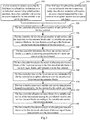
- a particular flow of a method for real-time transmission in a field broadband bus architecture over an industrial internet is as follows.
- the bus controller receives a fixed-rate service which is transmitted by the bus terminal in an uplink subframe over pre-allocated fixed-rate service resource blocks.
- the bus controller divides a data service into a fixed-rate service and a variable-rate service.
- the fixed-rate service refers to a service for transmitting data which requires more real-time transmission, or a stable transmission demand
- variable-rate service refers to a service for transmitting data which demands less real-time transmission, or a variable transmission demand, or an undecided transmission demand
- the transmission demand includes at least a bandwidth and a speed.
- Embodiments of the disclosure will not be limited to any particular division criterion, but a particular division criterion can be defined based upon the rough definition above of the fixed-rate service and the variable-rate service, so that both the bus controller and the bus terminal can know whether the transmitted data service is a fixed-rate service or a variable-rate service.
- the bus terminal transmitting the data service can transmit the fixed-rate service directly over the pre-allocated fixed-rate service resource blocks without being allocated any resource blocks dynamically in a real-time manner, to thereby guarantee a basic data transmission function of the bus terminal, and a real-time transmission for the fixed-rate service.
- the method further includes following operations.
- the bus controller will receive an access request transmitted by the bus terminal, where the access request includes at least a fixed-rate service transmission demand of the bus terminal.
- bus controller can receive the access request transmitted by the bus terminal in the following two instances.
- the bus controller will receive the access request which is sent the bus terminal in an uplink subframe.
- the bus controller will initially be powered on, and broadcast a message to the respective bus terminals that they can access, and the respective bus terminals will transmit their access requests in an uplink subframe upon reception of the message.
- the bus controller will receive the access request transmitted by the bus terminal in an uplink random access system subframe arranged in the last special subframe in a preset signal frame structure.
- the architecture is powered on, and proceeds to stable operation, and if there is a new bus terminal to access, it will transmit an access request in an uplink random access system subframe in a special frame.
- the bus terminal initially accessing at the physical layer firstly reports a demand for transmission of fixed-rate service for the effect that the bus controller can reserve channel resources at the physical layer for the fixed-rate service so that the fixed-rate data service for which a highly real-time characteristic is required can be subsequently transmitted in a real-time manner.
- a preset number of sub-carriers are allocated for the bus terminal, and the preset number of sub-carriers are divided into the fixed-rate service resource blocks and the variable-rate service resource blocks in a time domain according to the fixed-rate service transmission demand of the bus terminal, where a fixed-rate service is transmitted over the fixed-rate service resource blocks, and a variable-rate service is transmitted over the variable-rate service resource blocks.
- the resource blocks are divided over the sub-carriers allocated for the bus terminal according to the fixed-rate service transmission demand so that a demand for the resource blocks over which the fixed-rate service is transmitted is preferentially satisfied.
- Fig.4 is illustrated a schematic diagram of division into resource blocks according to some embodiments of the disclosure.
- Fig.4 there are four bus terminals, which a bus terminal A, a bus terminal B, a bus terminal C, and a bus terminal D respectively.
- Three sub-carriers are allocated for each of these four bus terminals in the frequency domain of uplink and downlink subframes, and resource blocks over the sub-carriers are divided respectively for each bus terminal into the fixed-rate service resource blocks and the variable-rate service resource blocks in the time domain of uplink and downlink subframes.
- channel resources at the physical layer are divided, sub-carriers are allocated respectively for each bus terminal, and resources over the sub-carriers of each bus terminal are divided into the fixed-rate service resource blocks and the variable-rate service resource blocks, so that corresponding data services can be transmitted respectively over divided resource blocks to thereby avoid collision between data transmission so as to guarantee the basic function and the reliability of transmitting a data service by the bus terminal; and a fixed-rate service can be transmitted preferentially to thereby enable the data service, for which a highly real-time characteristic is required, to be transmitted preferentially.
- the fixed-rate service resource blocks are determined as a result of allocating the resource blocks for the fixed-rate service of the bus terminal.
- the result is transmitted to the bus terminal so that the bus terminal transmits the fixed-rate service according to the result.
- the result of allocating the resource blocks for the fixed-rate service is broadcasted in the first downlink subframe of the next signal frame.
- the result of allocating the resource blocks for the fixed-rate service of the bus terminal i.e., a result of scheduling the resource blocks
- the result is broadcasted and notified to the bus terminal. Since there is a stable transmission bandwidth of the fixed-rate service, the result can be determined during the access, so the result is broadcasted only once.
- the bus controller receives a variable-rate service transmission demand transmitted by the bus terminal in the uplink subframe, allocates resource blocks for a variable-rate service of the bus terminal among pre-allotted variable-rate service resource blocks according to the variable-rate service transmission demand, and transmits a result of allocating the resource blocks to the bus terminal so that the bus terminal transmits the variable-rate service according to the result of allocating the resource blocks.
- the step 310 is performed optionally as follows.
- the bus controller receives the variable-rate service transmission demand transmitted by the bus terminal in an uplink subframe.
- the bus terminal needs to firstly report the variable-rate service transmission demand during transmission of the data service at the physical layer, and the bus controller allocates the resource blocks dynamically.
- the bus controller allocates the resource blocks for the variable-rate service of the bus terminal among the pre-allotted variable-rate service resource blocks according to the variable-rate service transmission demand.
- bus controller transmits the result of allocating the resource blocks to the bus terminal so that the bus terminal transmits the variable-rate service according to the result of allocating the resource blocks.
- the bus controller broadcasts the result of allocating the resource blocks in the first downlink subframe of the next signal frame.
- bus controller further allocates the resource blocks for the variable-rate service as follows:
- the bus controller will determine a priority of each variable-rate service respectively according to the type of each variable-rate service, and a preset mapping relationship between a priority and a type of variable-rate service.
- variable-rate services can be divided into three general priority levels, including a real-time priority (a first priority), a wait priority (a second priority), and a bandwidth priority (a third priority), according to their real-time characteristics, wait periods of time, and bandwidth demands thereof, and the variable-rate services at the respective general priority levels can be further subdivided respectively.
- a real-time priority a first priority
- a wait priority a second priority
- a bandwidth priority a third priority
- a service at a high priority among the real-time priority is a service for which a highly real-time characteristic, a short delay, low dithering, etc., are required, and a service at a low priority among the real-time priority is a service for which a real-time characteristic, a delay, dithering, etc., are less required.
- a service at a high priority among the wait priority is a service for which there is a long wait period of time for transmitting data to be transmitted, and a service at a low priority among the wait priority is a service for which there is a short wait period of time for transmitting data to be transmitted.
- a service at a high priority among the bandwidth priority is a service for which there is a high bandwidth demand for transmitting data to be transmitted, and a service at a low priority among the bandwidth priority is a service for which there is a low bandwidth demand for transmitting data to be transmitted.
- resource blocks are allocated respectively for each variable-rate service among the pre-allotted variable-rate service resource blocks according to the priority of the each variable-rate service, and the result of allocating the resource blocks is transmitted to the bus terminal so that the bus terminal transmits the each variable-rate service correspondingly according to the result of allocating the resource blocks.
- the priorities of the variable-rate services are determined so that the variable-rate services at the high priorities can be transmitted preferentially over the resource blocks to thereby further improve the real-time characteristic of transmitting the data services.
- a priority can also be determined for a fixed-rate service as described above, and in order to allocate the fixed-rate service resource blocks for the fixed-rate service, if the bus terminal reports a number of fixed-rate services when a connection is being set up, then a priority of each fixed-rate service may be determined respectively according to the type of each fixed-rate service, and a preset mapping relationship between a priority and a type of fixed-rate service; and resource blocks may be allocated respectively for each variable-rate service among pre-allotted variable-rate service resource blocks according to the priority of the each variable-rate service, and a result of allocating the resource blocks may be transmitted to the bus terminal so that the bus terminal transmits the each fixed-rate service correspondingly according to the result of allocating the resource blocks.
- data services are divided into fixed-rate services and variable-rate services, and correspondingly channel resources are divided into the fixed-rate service resource blocks and the variable-rate service resource blocks, so the fixed-rate service resource blocks can be reserved for a fixed-rate service, the variable-rate service resource blocks can be reserved for a variable-rate service, and the resource blocks can be allocated dynamically for a variable-rate service according to the priority thereof among the variable-rate service resource blocks, thus avoiding in effect collision from occurring in transmission of the data services, improving the reliability of transmitting the data services in the system, and also transmitting the data services in a real-time manner, and improving the real-time characteristic of the transmission.
- a process of performing a method for real-time transmission in a field broadband bus architecture over an industrial internet is as follows.
- a bus controller will receive an access request transmitted by the bus terminal in an uplink subframe.
- the access request includes at least a fixed-rate service transmission demand of the bus terminal.
- the bus controller will receive an access request transmitted by a bus terminal in an uplink random access system subframe.
- the uplink random access system subframe is located in the last special frame of a preset signal frame structure.
- the access request includes at least a fixed-rate service transmission demand of the bus terminal.
- the bus controller allocates a preset number of sub-carriers for the bus terminal.
- the bus controller divides the preset number of sub-carriers into the fixed-rate service resource blocks and the variable-rate service resource blocks in the time domain according to the fixed-rate service transmission demand of the bus terminal.
- the bus controller determines the fixed-rate service resource blocks as a result of allocating resource blocks of a fixed-rate service of the bus terminal.
- the bus controller broadcasts the result of allocating the resource blocks of the fixed-rate service in the first downlink subframe of the next signal frame, and transmits it to the bus terminal.
- the bus controller receives the fixed-rate service transmitted by the bus terminal in an uplink subframe over the pre-allocated fixed-rate service resource blocks.
- the bus terminal can transmit the fixed-rate service directly over the pre-allocated fixed-rate service resource blocks instead of further requesting for resource blocks, to thereby improve real-time transmission of data.
- the bus controller receives a variable-rate service transmission demand transmitted by the bus terminal in the uplink subframe.
- the bus controller allocates resource blocks for a variable-rate service of the bus terminal among the pre-allotted variable-rate service resource blocks according to the variable-rate service transmission demand.
- the bus controller broadcasts a result of allocating the resource blocks in the first downlink subframe of the next signal frame, and transmits it to the bus terminal.
- the bus terminal can transmit the variable-rate service according to the result of allocating the resource blocks of the variable-rate service.
- some embodiments of the disclosure provide an apparatus for real-time transmission in a field broadband bus architecture over an industrial internet
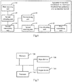
- the field broadband bus architecture over an industrial internet includes: a bus controller, at least one bus terminal, and a two-wire bus over which the bus controller and the bus terminal are connect to constitute a network, the bus controller communicates with any one bus terminal, and the respective bus terminals communicate with each other, using the OFDM technology, and sub-carriers occupied by the respective bus terminals do not interfere with each other; and the apparatus for real-time transmission in a field broadband bus architecture over an industrial internet particularly includes following units.
- a first receiving unit 60 is configured to receive a fixed-rate service transmitted by the bus terminal in an uplink subframe over pre-allocated fixed-rate service resource blocks.
- a second receiving unit 61 is configured to receive a variable-rate service transmission demand transmitted by the bus terminal in the uplink subframe.
- a first allocating unit 62 is configured to allocate resource blocks for a variable-rate service of the bus terminal among pre-allotted variable-rate service resource blocks according to the variable-rate service transmission demand.
- a first transmitting unit 63 is configured to transmit a result of allocating the resource blocks to the bus terminal so that the bus terminal transmits the variable-rate service according to the result of allocating the resource blocks.
- the apparatus further includes following units.
- a third receiving unit 64 is configured to receive an access request transmitted by the bus terminal when the bus terminal initially accesses, where the access request includes at least a fixed-rate service transmission demand of the bus terminal;
- a second allocating unit 65 is configured to allocate a preset number of sub-carriers for the bus terminal, and to divide the preset number of sub-carriers into the fixed-rate service resource blocks and the variable-rate service resource blocks in the time domain according to the fixed-rate service transmission demand of the bus terminal, where the fixed-rate service is transmitted over the fixed-rate service resource blocks, and the variable-rate service is transmitted over the variable-rate service resource blocks.
- a second transmitting unit 66 is configured to determine the fixed-rate service resource blocks as the allocation result of the resource blocks of the fixed-rate service of the bus terminal, and to transmit the result of allocating the resource blocks of the fixed-rate service to the bus terminal so that the bus terminal transmits the fixed-rate service according to the result of allocating the resource blocks of the fixed-rate service.
- the third receiving unit 64 for receiving the access request transmitted by the bus terminal is configured to perform following operation.
- the field broadband bus architecture over an industrial internet is being initialized into operation, receiving the access request which is sent the bus terminal in the uplink subframe; or if the field broadband bus architecture over an industrial internet is operating stably, receiving the access request which is sent the bus terminal in an uplink random access system subframe which is in the last special frame of a preset signal frame structure.
- the first allocating unit 62 is further configured to perform following operation.
- the first transmitting unit 63 is configured to transmit the result of allocating the resource blocks to the bus terminal so that the bus terminal transmits the each data service correspondingly according to the result of allocating the resource blocks.
- the first transmitting unit 63 for transmitting the result of allocating the resource blocks to the bus terminal is configured to broadcast the result of allocating the resource blocks in a first downlink subframe of a next signal frame.
- the second transmitting unit 66 for transmitting the result of allocating the resource blocks of the fixed-rate service to the bus terminal is configured to broadcast the result of allocating the resource blocks of the fixed-rate service in the first downlink subframe of the next signal frame.
- Some embodiments of the disclosure provide a computer readable storage medium on which computer program is stored, where the computer program is configured to be executed by a processor to perform the method for real-time transmission in a field broadband bus architecture over an industrial internet according to any one of the embodiments above.
- Fig.7 is illustrated a schematic structural diagram of a computing device according to some embodiments of the disclosure.
- a computing device which can include a processor 710 (Center Processing Unit, CPU), a memory 720, an input device 730, an output device 740, etc., where the input device 730 can include a keyboard, a mouse, a touch screen, etc., and the output device 740 can include a display device, e.g., a Liquid Crystal Display (LCD), a Cathode Ray Tube (CRT) display, etc.
- a display device e.g., a Liquid Crystal Display (LCD), a Cathode Ray Tube (CRT) display, etc.
- LCD Liquid Crystal Display
- CRT Cathode Ray Tube
- the memory 720 can include a Read Only Memory (ROM) and a Random Access Memory (RAM), and provides the processor 710 with program instructions and data stored in the memory 720.
- the memory 720 can be configured to store the program above configured to perform the method for real-time transmission in a field broadband bus architecture over an industrial internet.
- the processor 710 is configured to invoke program instructions stored in the memory 720, and to execute the program instructions to perform following operations.
- processor 710 is further configured to perform following operations.
- the processor 710 for receiving the access request transmitted by the bus terminal is configured to perform following operation.
- the field broadband bus architecture over an industrial internet is being initialized into operation, receiving the access request which is sent the bus terminal in the uplink subframe; or if the field broadband bus architecture over an industrial internet is operating stably, receiving the access request which is sent the bus terminal in an uplink random access system subframe in the last special frame of a preset signal frame structure.
- each OFDM symbol in the uplink random access system subframe carries both a data signal and an uplink pilot signal, where the sub-carriers occupied by the data signal and the uplink pilot signal in the uplink random access system subframe are allocated according to a preset proportion, and the data signal includes at least the access request.
- each OFDM symbol in the uplink subframe carries an uplink pilot signal in addition to a data signal, where the uplink pilot signal instructs the bus controller to perform a channel estimation.
- the sub-carriers occupied by the data signal and the uplink pilot signal in the uplink subframe are allocated according to a preset proportion.
- processor 710 is further configured to perform following operations.
- variable-rate service transmission demand determining a priority of each variable-rate service respectively according to the type of each variable-rate service, and a preset mapping relationship between a priority and a type of variable-rate service, and allocating resource blocks respectively for each variable-rate service among the pre-allotted variable-rate service resource blocks according to the priority of the each data service.
- the processor 710 for transmitting the result of allocating the resource blocks to the bus terminal is configured to broadcast the result of allocating the resource blocks in a first downlink subframe of a next signal frame.
- the processor 710 for transmitting the result of allocating the resource blocks of the fixed-rate service to the bus terminal is configured to broadcast the result of allocating the resource blocks of the fixed-rate service in the first downlink subframe of the next signal frame.
- the field broadband bus architecture over an industrial internet includes: a bus controller, at least one bus terminal, and a two-wire bus over which the bus controller and the bus terminal are connect to constitute a network, the bus controller communicates with any one bus terminal, and the respective bus terminals communicate with each other, using the OFDM technology, and sub-carriers occupied by the respective bus terminals do not interfere with each other; and the method particularly includes: the bus controller receives a fixed-rate service transmitted by the bus terminal in an uplink subframe over pre-allocated fixed-rate service resource blocks; and the bus controller receives a variable-rate service transmission demand transmitted by the bus terminal in the uplink subframe, allocates resource blocks for a variable-rate service of the bus terminal among pre-allotted variable-rate service resource blocks according to the variable-rate service transmission demand, and transmits a result of allocating the resource blocks to the bus terminal so that the bus terminal transmits the variable-rate service according to the result of allocating the resource blocks.
- the OFDM technology is introduced to the industrial field bus, the transmission bandwidth and rate can be further improved using the multi-carrier technology
- the data services are divided into fixed-rate services and variable-rate services
- the channel resources are divided into the fixed-rate service resource blocks and the variable-rate service resource blocks, where the fixed-rate service resource blocks of the fixed-rate services are pre-allocated instead of being allocated dynamically, and the variable-rate service resource blocks are allocated dynamically in a real-time manner for the variable-rate services, thus avoiding in effect confliction from occurring between the data transmitted services, and improving the reliability of transmitting the data services in the system; and also transmitting the data services in a real-time manner, and improving real-time transmission thereof.
- the embodiments of the disclosure can be embodied as a method, a system or a computer program product. Therefore the disclosure can be embodied in the form of an all-hardware embodiment, an all-software embodiment or some embodiments of software and hardware in combination. Furthermore the disclosure can be embodied in the form of a computer program product embodied in one or more computer useable storage mediums (including but not limited to a disk memory, a CD-ROM, an optical memory, etc.) in which computer useable program codes are contained.
- These computer program instructions can also be stored into a computer readable memory capable of directing the computer or the other programmable data processing device to operate in a specific manner so that the instructions stored in the computer readable memory create an article of manufacture including instruction means which perform the functions specified in the flow(s) of the flow chart and/or the block(s) of the block diagram.
- These computer program instructions can also be loaded onto the computer or the other programmable data processing device so that a series of operational steps are performed on the computer or the other programmable data processing device to create a computer implemented process so that the instructions executed on the computer or the other programmable device provide steps for performing the functions specified in the flow(s) of the flow chart and/or the block(s) of the block diagram.
Landscapes
- Engineering & Computer Science (AREA)
- Signal Processing (AREA)
- Computer Networks & Wireless Communication (AREA)
- General Engineering & Computer Science (AREA)
- Theoretical Computer Science (AREA)
- Quality & Reliability (AREA)
- Physics & Mathematics (AREA)
- General Physics & Mathematics (AREA)
- Computer Hardware Design (AREA)
- Manufacturing & Machinery (AREA)
- Automation & Control Theory (AREA)
- Small-Scale Networks (AREA)
- Data Exchanges In Wide-Area Networks (AREA)
- Communication Control (AREA)
Claims (13)
- Verfahren zur Echtzeitübertragung in einer Feldbreitbandbus-Architektur über ein industrielles Internet, wobei die Feldbreitbandbus-Architektur über ein industrielles Internet umfasst: einen Buscontroller, mindestens ein Busterminal und einen Zweidrahtbus, über den der Buscontroller und das Busterminal verbunden sind, um ein Netzwerk zu bilden, wobei der Buscontroller mit jedem beliebigen Busterminal unter Verwendung einer Orthogonal-Frequenz-Divisions-Multiplexing, OFDM, -Technologie kommuniziert und die jeweiligen Busterminals kommunizieren ebenfalls unter Verwendung der OFDM-Technologie miteinander, und wobei Unterträger, die von den jeweiligen Busterminals belegt sind, einander nicht stören; und das Verfahren umfasst:Empfangen, durch den Buscontroller, eines Dienstes mit fester Rate, der von dem Busterminal in einem Uplink-Unterrahmen über vorab zugewiesene Ressourcenblöcke für den Dienst mit fester Rate übertragen wird; wobei der Dienst mit fester Rate sich auf einen Dienst zum Übertragen von Daten bezieht, der eine Echtzeitübertragung oder eine stabile Übertragungsnachfrage erfordert, undEmpfangen, durch den Buscontroller, einer von dem Busterminal in dem Uplink-Unterrahmen während der Übertragung eines Datendienstes auf einer physikalischen Schicht gemeldeten Anforderung für die Übertragung eines Dienstes mit variabler Rate, Zuweisen von Ressourcenblöcken für einen Dienst mit variabler Rate des Busterminals unter im voraus zugewiesenen Ressourcenblöcken für den Dienst mit variabler Rate entsprechend der Anforderung für die Übertragung des Dienstes mit variabler Rate, und Übertragen eines Ergebnisses der Zuweisung der Ressourcenblöcke an das Busterminal, so dass das Busterminal den Dienst mit variabler Rate entsprechend dem Ergebnis der Zuweisung der Ressourcenblöcke überträgt;wobei das Verfahren ferner umfasst:wenn das Busterminal anfangs zugreift, Empfangen, durch den Buscontroller, einer von dem Busterminal übertragenen Zugriffsanforderung, wobei die Zugriffsanforderung mindestens eine Anforderung für die Übertragung eines Dienstes mit fester Rate des Busterminals umfasst;Zuweisen einer voreingestellten Anzahl von Unterträgern für das Busterminal, und Unterteilen der voreingestellten Anzahl von Unterträgern in die Ressourcenblöcke für den Dienst mit fester Rate und die Ressourcenblöcken für den Dienst mit variabler Rate in einem Zeitbereich entsprechend der Anforderung für die Übertragung eines Dienstes mit fester Rate des Busterminal, wobei der Dienst mit fester Rate über die Ressourcenblöcke des Dienstes mit fester Rate übertragen wird und der Dienst mit variabler Rate über die Ressourcenblöcke des Dienstes mit variabler Rate übertragen wird; undBestimmen der Ressourcenblöcke des Dienstes mit fester Rate als ein Ergebnis der Zuweisung der Ressourcenblöcke des Dienstes mit fester Rate des Busterminals, und Übertragen des Ergebnisses der Zuweisung der Ressourcenblöcke des Dienstes mit fester Rate an das Busterminal, so dass das Busterminal den Dienst mit fester Rate entsprechend dem Ergebnis der Zuweisung der Ressourcenblöcke des Dienstes mit fester Rate überträgt.
- Das Verfahren nach Anspruch 1, wobei der Empfang, durch den Buscontroller, der von dem Busterminal übertragenen Zugriffsanforderung umfasst:wenn die Feldbandbandbus-Architektur über ein industrielles Internet in Betrieb genommen wird, Empfangen, durch den Buscontroller, der Zugriffsanforderung, die von dem Busterminal in dem Uplink-Unterrahmen gesendet wird; oderwenn die Feldbus-Breitband-Busarchitektur über ein industrielles Internet stabil arbeitet, Empfangen, durch den Biscontroller, der Zugriffsanforderung, die von dem Busterminal in einem Uplink-Random-Access-Systemunterrahmen in einem letzten speziellen Rahmen einer voreingestellten Signalrahmenstruktur gesendet wird.
- Das Verfahren nach Anspruch 2, wobei jedes OFDM-Symbol in dem Uplink-Random-Access-Systemunterrahmen sowohl ein Datensignal als auch ein Uplink-Pilotsignal trägt, wobei Unterträger, die von dem Datensignal und dem Uplink-Pilotsignal in dem Uplink-Random-Access-Systemunterrahmen belegt sind, gemäß einem voreingestellten Verhältnis zugewiesen werden, und wobei das Datensignal mindestens die Zugriffsanforderung umfasst.
- Das Verfahren nach Anspruch 1 oder 2, wobei jedes OFDM-Symbol in dem Uplink-Unterrahmen zusätzlich zu einem Datensignal ein Uplink-Pilotsignal trägt, wobei das Uplink-Pilotsignal den Buscontroller anweist, eine Kanalschätzung durchzuführen; und
wobei Unterträger, die durch das Datensignal und das Uplink-Pilotsignal im Uplink-Unterrahmen belegt sind, nach einem vorgegebenen Verhältnis zugewiesen werden. - Das Verfahren nach Anspruch 1, wobei das Verfahren ferner umfasst:Bestimmen einer Priorität jedes Datendienstes jeweils gemäß einem Typ des jeweiligen Datendienstes und einer voreingestellten Abbildungsbeziehung zwischen einer Priorität und dem Typ des Datendienstes, wobei die Datendienste Dienste mit variabler Rate und Dienste mit fester Rate umfassen; undZuweisen von Ressourcenblöcken jeweils für jeden Datendienst unter den vorab zugewiesenen Datendienst-Ressourcenblöcken entsprechend der Priorität des jeweiligen Datendienstes, und Übertragen des Ergebnisses der Zuweisung der Ressourcenblöcke an das Busterminal, so dass das Busterminal den jeweiligen Datendienst entsprechend dem Ergebnis der Zuweisung der Ressourcenblöcke überträgt.
- Das Verfahren nach einem der Ansprüche 1 bis 5, wobei das Übertragen des Ergebnisses der Zuweisung der Ressourcenblöcke an das Busterminal umfasst: Broadcasting des Ergebnisses der Zuweisung der Ressourcenblöcke in einem ersten Downlink-Unterrahmen eines nächsten Signalrahmens; und
Das Übertragen des Ergebnisses der Zuweisung der Ressourcenblöcke des Dienstes mit fester Rate an das Busterminal umfasst: Broadcasting des Ergebnisses der Zuweisung der Ressourcenblöcke des Dienstes mit fester Rate in einem ersten Downlink-Unterrahmen des nächsten Signalrahmens. - Vorrichtung zur Echtzeitübertragung in einer Feldbreitbandbus-Architektur über ein industrielles Internet, wobei die Feldbreitbandbus-Architektur über ein industrielles Internet umfasst: einen Buscontroller, mindestens ein Busterminal und einen Zweidrahtbus, über den der Buscontroller und das Busterminal verbunden sind, um ein Netzwerk zu bilden, wobei der Buscontroller mit jedem beliebigen Busterminal unter Verwendung einer Orthogonal-Frequenz-Divisions-Multiplexing, OFDM, -Technologie kommuniziert und die jeweiligen Busterminals kommunizieren ebenfalls unter Verwendung der OFDM-Technologie miteinander, und wobei Unterträger, die von den jeweiligen Busterminals belegt sind, einander nicht stören; und die Vorrichtung umfasst:eine erste Empfangseinheit (60) eingerichtet, um einen Dienst mit fester Rate, der von dem Busterminal in einem Uplink-Unterrahmen über vorab zugewiesene Ressourcenblöcke für den Dienst mit fester Rate übertragen wird, zu empfangen, wobei der Dienst mit fester Rate sich auf einen Dienst zum Übertragen von Daten bezieht, der eine Echtzeitübertragung oder eine stabile Übertragungsnachfrage erfordert;eine zweite Empfangseinheit (61) eingerichtet, um eine von dem Busterminal in dem Uplink-Unterrahmen während der Übertragung eines Datendienstes auf einer physikalischen Schicht gemeldeten Anforderung für die Übertragung eines Dienstes mit variabler Rate zu empfangen;eine erste Zuweisungseinheit (61) eingerichtet, um Ressourcenblöcke für einen Dienst mit variabler Rate des Busterminals unter im voraus zugewiesenen Ressourcenblöcken für den Dienst mit variabler Rate entsprechend der Anforderung für die Übertragung des Dienstes mit variabler Rate zuzuweisen; undeine erste Übertragungseinheit (63) eingerichtet, um ein Ergebniss der Zuweisung der Ressourcenblöcke an das Busterminal zu übertragen, so dass das Busterminal den Dienst mit variabler Rate entsprechend dem Ergebnis der Zuweisung der Ressourcenblöcke überträgt;wobei die Vorrichtung ferner umfasst:eine dritte Empfangseinheit (64) eingerichtet, um eine von dem Busterminal übertragene Zugriffsanforderung zu empfangen, wobei die Zugriffsanforderung mindestens eine Anforderung für die Übertragung eines Dienstes mit fester Rate des Busterminals umfasst;eine zweite Zuweisungseinheit (65) eingerichtet, um eine voreingestellte Anzahl von Unterträgern für das Busterminal zuzuweisen, und die voreingestellte Anzahl von Unterträgern in die Ressourcenblöcke für den Dienst mit fester Rate und die Ressourcenblöcken für den Dienst mit variabler Rate in einem Zeitbereich entsprechend der Anforderung für die Übertragung eines Dienstes mit fester Rate des Busterminal zu unterteilen, wobei der Dienst mit fester Rate über die Ressourcenblöcke des Dienstes mit fester Rate übertragen wird und der Dienst mit variabler Rate über die Ressourcenblöcke des Dienstes mit variabler Rate übertragen wird; undeine zweite Übertragungseinheit (66) eingerichtet, um die Ressourcenblöcke des Dienstes mit fester Rate als ein Ergebnis der Zuweisung der Ressourcenblöcke des Dienstes mit fester Rate des Busterminals zu bestimmen, und das Ergebniss der Zuweisung der Ressourcenblöcke des Dienstes mit fester Rate an das Busterminal zu übertragen, so dass das Busterminal den Dienst mit fester Rate entsprechend dem Ergebnis der Zuweisung der Ressourcenblöcke des Dienstes mit fester Rate überträgt.
- Die Vorrichtung nach Anspruch 7, wobei die dritte Empfangseinheit (64) zum Empfang der von dem Busterminal übertragenen Zugriffsanforderung eingerichtet ist:wenn die Feldbandbandbus-Architektur über ein industrielles Internet in Betrieb genommen wird, die Zugriffsanforderung, die von dem Busterminal in dem Uplink-Unterrahmen gesendet wird, zu empfangen; oderwenn die Feldbus-Breitband-Busarchitektur über ein industrielles Internet stabil arbeitet, die Zugriffsanforderung, die von dem Busterminal in einem Uplink-Random-Access-Systemunterrahmen in einem letzten speziellen Rahmen einer voreingestellten Signalrahmenstruktur gesendet wird, zu empfangen.
- Die Vorrichtung nach Anspruch 8, wobei jedes OFDM-Symbol in dem Uplink-Random-Access-Systemunterrahmen sowohl ein Datensignal als auch ein Uplink-Pilotsignal trägt, wobei Unterträger, die von dem Datensignal und dem Uplink-Pilotsignal in dem Uplink-Random-Access-Systemunterrahmen belegt sind, gemäß einem voreingestellten Verhältnis zugewiesen werden, und wobei das Datensignal mindestens die Zugriffsanforderung umfasst.
- Die Vorrichtung nach Anspruch 7 oder 8, wobei jedes OFDM-Symbol in dem Uplink-Unterrahmen zusätzlich zu einem Datensignal ein Uplink-Pilotsignal trägt, wobei das Uplink-Pilotsignal den Buscontroller anweist, eine Kanalschätzung durchzuführen; und
wobei Unterträger, die durch das Datensignal und das Uplink-Pilotsignal im Uplink-Unterrahmen belegt sind, nach einem vorgegebenen Verhältnis zugewiesen werden. - Die Vorrichtung nach Anspruch 7, wobei die erste Zuweisungseinheit (62) ferner eingerichtet ist:um eine Priorität jedes Datendienstes jeweils gemäß einem Typ des jeweiligen Datendienstes und einer voreingestellten Abbildungsbeziehung zwischen einer Priorität und dem Typ des jeweiligen Datendienstes zu bestimmen, wobei die Datendienste Dienste mit variabler Rate und Dienste mit fester Rate umfassen; undRessourcenblöcken jeweils für jeden Datendienst unter den vorab zugewiesenen Datendienst-Ressourcenblöcken entsprechend der Priorität des jeweiligen Datendienstes zuzuweisen; undwobei die erste Übertragungseinheit (63) eingerichtet ist, um das Ergebniss der Zuweisung der Ressourcenblöcke an das Busterminal, zu übertragen so dass das Busterminal den jeweiligen Datendienst entsprechend dem Ergebnis der Zuweisung der Ressourcenblöcke überträgt; wobei die zweite Übertragungseinheit (66) zum Übertragen des Ergebnisses der Zuweisung der Ressourcenblöcke an das Busterminal eingerichtet ist, um das Ergebniss der Zuweisung der Ressourcenblöcke in einem ersten Downlink-Unterrahmen eines nächsten Signalrahmens zu broadcasten; undwobei die zweite Übertragungseinheit (66) zum Übertragen des Ergebnisses der Zuweisung der Ressourcenblöcke des Dienstes mit fester Rate an das Busterminal eingerichtet ist, um das Ergebnis der Zuweisung der Ressourcenblöcke des Dienstes mit fester Rate in einem ersten Downlink-Unterrahmen des nächsten Signalrahmens zu broadcasten.
- Computerlesbares Speichermedium, auf dem ein Computerprogramm gespeichert ist, wobei das Computerprogramm eingerichtet ist, um durch einen Prozessor ausgeführt zu werden, um Schritte in dem Verfahren gemäß einem der Ansprüche 1 bis 6 durchzuführen.
- Computervorrichtung, die einen Prozessor (710) umfasst, der eingerichtet ist, um ein in einem Speicher (720) gespeichertes Computerprogramm auszuführen, um Schritte in dem Verfahren gemäß einem der Ansprüche 1 bis 6 auszuführen.
Applications Claiming Priority (1)
| Application Number | Priority Date | Filing Date | Title |
|---|---|---|---|
| CN201710542984.XA CN107528680B (zh) | 2017-07-05 | 2017-07-05 | 基于工业互联网现场层总线架构实时传输方法及装置 |
Publications (2)
| Publication Number | Publication Date |
|---|---|
| EP3425832A1 EP3425832A1 (de) | 2019-01-09 |
| EP3425832B1 true EP3425832B1 (de) | 2020-08-12 |
Family
ID=60748253
Family Applications (1)
| Application Number | Title | Priority Date | Filing Date |
|---|---|---|---|
| EP17210905.0A Active EP3425832B1 (de) | 2017-07-05 | 2017-12-28 | Verfahren und vorrichtung zur echtzeitübertragung in einer breitbandigen busfeldarchitektur über ein industrielles internet |
Country Status (5)
| Country | Link |
|---|---|
| US (1) | US10462785B2 (de) |
| EP (1) | EP3425832B1 (de) |
| JP (1) | JP6530520B2 (de) |
| CN (1) | CN107528680B (de) |
| ES (1) | ES2828737T3 (de) |
Families Citing this family (19)
| Publication number | Priority date | Publication date | Assignee | Title |
|---|---|---|---|---|
| EP3790348A4 (de) * | 2018-06-21 | 2021-05-12 | Huawei Technologies Co., Ltd. | Kommunikationsverfahren, basisstation und endgerät |
| DE102018218721A1 (de) * | 2018-10-31 | 2020-04-30 | Robert Bosch Gmbh | Teilnehmerstation für ein serielles Bussystem und Verfahren zum Senden einer Nachricht in einem seriellen Bussystem |
| CN110247834A (zh) * | 2019-07-05 | 2019-09-17 | 北京神经元网络技术有限公司 | 节点设备、高速工业通信系统和通讯的方法 |
| CN112448798A (zh) * | 2019-08-29 | 2021-03-05 | 北京东土军悦科技有限公司 | 一种军事阵地通信系统、方法、装置和存储介质 |
| CN112448797A (zh) * | 2019-08-29 | 2021-03-05 | 北京东土军悦科技有限公司 | 一种军用车载通信系统、方法、装置和存储介质 |
| CN112491767B (zh) * | 2019-09-11 | 2023-01-06 | 北京东土科技股份有限公司 | 系统时间同步方法、装置、计算机设备及存储介质 |
| CN115051780B (zh) * | 2019-09-19 | 2024-02-13 | 北京东土科技股份有限公司 | 物理资源块分配方法、装置、设备及存储介质 |
| CN112543085B (zh) * | 2019-09-23 | 2023-01-06 | 北京东土科技股份有限公司 | 传输用子载波的选择方法、装置、设备及存储介质 |
| CN112583541A (zh) * | 2019-09-27 | 2021-03-30 | 北京东土科技股份有限公司 | 基于二次扩展的高速工业控制总线系统 |
| CN113098744B (zh) * | 2019-12-23 | 2022-12-27 | 北京神经元网络技术有限公司 | 用户节点发现方法及装置、电子设备及存储介质 |
| CN113098703A (zh) * | 2019-12-23 | 2021-07-09 | 北京神经元网络技术有限公司 | 基于优先级的动态带宽分配方法、电子设备及存储器 |
| CN113098795A (zh) * | 2019-12-23 | 2021-07-09 | 北京神经元网络技术有限公司 | 高速工业总线通信系统中基于动态网络的预留带宽分配方法和装置 |
| CN113038609B (zh) * | 2019-12-25 | 2023-04-18 | 北京东土科技股份有限公司 | 一种基于通信需求的带宽资源分配方法、装置及设备 |
| CN113038570B (zh) * | 2019-12-25 | 2023-01-06 | 北京东土科技股份有限公司 | 一种用户节点的接入控制方法、装置、设备及存储介质 |
| CN111615152B (zh) * | 2020-06-11 | 2023-07-21 | 中国人民解放军军事科学院军事科学信息研究中心 | 一种宽带上行链路的资源分配方法 |
| NL2025843B1 (en) | 2020-06-17 | 2022-02-17 | Emanuel Johannes Van Riel Rudolf | Ballistic panel |
| CN112291128B (zh) * | 2020-10-29 | 2022-10-21 | 黑芝麻智能科技(上海)有限公司 | 基于总线的通信系统、片上系统和用于其的方法 |
| CN112894805B (zh) * | 2020-12-29 | 2022-08-19 | 北京东土科技股份有限公司 | 一种基于工业宽带总线的机器人通信方法及系统 |
| US20240140334A1 (en) * | 2021-12-03 | 2024-05-02 | Lg Electronics Inc. | Vehicle communication device and display apparatus for vehicle including the same |
Family Cites Families (15)
| Publication number | Priority date | Publication date | Assignee | Title |
|---|---|---|---|---|
| JP2001333082A (ja) * | 2000-03-16 | 2001-11-30 | Sharp Corp | 無線バスシステム、無線通信装置及び登録通信方法 |
| JP2002237797A (ja) * | 2001-02-13 | 2002-08-23 | Victor Co Of Japan Ltd | 直交周波数分割多重信号生成装置、及び直交周波数分割多重信号復号装置 |
| KR100455285B1 (ko) * | 2001-09-06 | 2004-11-12 | 삼성전자주식회사 | 다중 반송파 방식을 이용한 데이타 무선 통신 방법 및장치와 이를 위한 전송 프레임 포맷 |
| US7362817B2 (en) * | 2003-07-18 | 2008-04-22 | Broadcom Corproation | UWB (Ultra Wide Band) interference mitigation |
| EP1507376A3 (de) * | 2003-08-12 | 2011-05-25 | Broadcom Corporation | Selektive Gewichtung von Symbolen in einem Empfänger |
| US7599377B2 (en) * | 2004-10-15 | 2009-10-06 | Temic Automotive Of North America, Inc. | System and method for tunneling standard bus protocol messages through an automotive switch fabric network |
| JP5157510B2 (ja) * | 2008-02-19 | 2013-03-06 | 富士通株式会社 | 無線通信制御方法および無線端末 |
| CN101567833A (zh) * | 2008-04-25 | 2009-10-28 | 江军 | 基于业务模型的多用户ofdm系统子载波分配方案 |
| DE102008002738B4 (de) * | 2008-06-27 | 2010-03-11 | Airbus Deutschland Gmbh | Verfahren zum Erkennen eines fehlerhaften Knotens |
| WO2010021739A1 (en) * | 2008-08-21 | 2010-02-25 | Ikanos Communications, Inc. | Method and apparatus for a data transmission in home networks |
| DE102010041368A1 (de) * | 2010-09-24 | 2012-04-19 | Robert Bosch Gmbh | Verfahren und Teilnehmerstation zum optimierten Übertragen von Daten zwischen Teilnehmerstationen eines Bussystems |
| US9280414B2 (en) * | 2011-03-01 | 2016-03-08 | As-International Association E.V. | Combination of error correction and error detection for transmitting digital data |
| US9363788B2 (en) * | 2011-11-09 | 2016-06-07 | Qualcomm Incorporated | Efficient variable rate for broadcast/multicast service |
| CN106209542B (zh) * | 2016-06-23 | 2019-08-02 | 北京东土科技股份有限公司 | 工业互联网现场层宽带总线架构系统 |
| CN105959195B (zh) * | 2016-06-23 | 2020-02-21 | 北京东土科技股份有限公司 | 工业互联网现场层宽带总线技术实现方法 |
-
2017
- 2017-07-05 CN CN201710542984.XA patent/CN107528680B/zh active Active
- 2017-12-28 EP EP17210905.0A patent/EP3425832B1/de active Active
- 2017-12-28 ES ES17210905T patent/ES2828737T3/es active Active
- 2017-12-29 US US15/859,003 patent/US10462785B2/en active Active
-
2018
- 2018-01-29 JP JP2018012912A patent/JP6530520B2/ja active Active
Non-Patent Citations (1)
| Title |
|---|
| None * |
Also Published As
| Publication number | Publication date |
|---|---|
| JP6530520B2 (ja) | 2019-06-12 |
| ES2828737T3 (es) | 2021-05-27 |
| EP3425832A1 (de) | 2019-01-09 |
| CN107528680B (zh) | 2020-09-22 |
| CN107528680A (zh) | 2017-12-29 |
| JP2019017058A (ja) | 2019-01-31 |
| US10462785B2 (en) | 2019-10-29 |
| US20190014574A1 (en) | 2019-01-10 |
Similar Documents
| Publication | Publication Date | Title |
|---|---|---|
| US10462785B2 (en) | Method and apparatus for real-time transmission in a field broadband bus architecture over an industrial internet | |
| EP3425833B1 (de) | System, das auf basis einer feldbreitbandbusarchitektur von industriellem internet implementiert ist | |
| US10805923B2 (en) | Allocating transmission resources in communication networks that provide low latency services | |
| CN108141328B (zh) | 用于蜂窝无线电通信中资源利用的消隐图案指示 | |
| IL264474B2 (en) | Information transmission method and information transmission device | |
| CN109495981B (zh) | 基于ofdm的数据传输方法、装置、设备和存储介质 | |
| WO2015106694A1 (zh) | 数据传输方法、基站以及用户设备 | |
| US11515988B2 (en) | Method and device for determining initial positions of downlink data channel | |
| CN110311770B (zh) | 基于ofdm通信体制的高速工业通信系统的时频复用方法 | |
| KR20200013815A (ko) | 다운링크 제어 정보 dci 송신 방법 및 장치 | |
| WO2021022747A1 (zh) | 数据发送方法、装置、计算机设备和存储介质 | |
| EP3979736A1 (de) | Datenmultiplex-übertragungsverfahren, basisstation, endgerät und speichermedium | |
| US11166304B2 (en) | Downlink control channel configuration method, network device, and terminal | |
| WO2020228544A1 (zh) | 一种随机接入上行共享信道配置方法、随机信道接入方法和设备 | |
| CN112469126A (zh) | 实时通信方法、装置、计算机设备及存储介质 | |
| CN107295661A (zh) | 一种下行数据传输及检测方法、装置、相关设备和系统 | |
| US10939425B2 (en) | Configuring wireless communications resources | |
| CN109586860B (zh) | 一种资源复用方法及装置、存储介质、终端、基站 | |
| CN112913154B (zh) | 目标变换矩阵的指示方法、设备、系统及存储介质 | |
| US8320322B2 (en) | Assignment method and base station apparatus using the assignment method | |
| CN104160773B (zh) | 信息上报方法、装置及系统 | |
| JP7346550B2 (ja) | ミニスロットを割り当てる方法、装置およびコンピュータ可読媒体 | |
| CN107888347B (zh) | 一种导频映射方法及装置 |
Legal Events
| Date | Code | Title | Description |
|---|---|---|---|
| PUAI | Public reference made under article 153(3) epc to a published international application that has entered the european phase |
Free format text: ORIGINAL CODE: 0009012 |
|
| STAA | Information on the status of an ep patent application or granted ep patent |
Free format text: STATUS: REQUEST FOR EXAMINATION WAS MADE |
|
| 17P | Request for examination filed |
Effective date: 20171228 |
|
| AK | Designated contracting states |
Kind code of ref document: A1 Designated state(s): AL AT BE BG CH CY CZ DE DK EE ES FI FR GB GR HR HU IE IS IT LI LT LU LV MC MK MT NL NO PL PT RO RS SE SI SK SM TR |
|
| AX | Request for extension of the european patent |
Extension state: BA ME |
|
| GRAP | Despatch of communication of intention to grant a patent |
Free format text: ORIGINAL CODE: EPIDOSNIGR1 |
|
| STAA | Information on the status of an ep patent application or granted ep patent |
Free format text: STATUS: GRANT OF PATENT IS INTENDED |
|
| INTG | Intention to grant announced |
Effective date: 20200324 |
|
| GRAS | Grant fee paid |
Free format text: ORIGINAL CODE: EPIDOSNIGR3 |
|
| GRAA | (expected) grant |
Free format text: ORIGINAL CODE: 0009210 |
|
| STAA | Information on the status of an ep patent application or granted ep patent |
Free format text: STATUS: THE PATENT HAS BEEN GRANTED |
|
| AK | Designated contracting states |
Kind code of ref document: B1 Designated state(s): AL AT BE BG CH CY CZ DE DK EE ES FI FR GB GR HR HU IE IS IT LI LT LU LV MC MK MT NL NO PL PT RO RS SE SI SK SM TR |
|
| REG | Reference to a national code |
Ref country code: CH Ref legal event code: EP |
|
| REG | Reference to a national code |
Ref country code: IE Ref legal event code: FG4D |
|
| REG | Reference to a national code |
Ref country code: DE Ref legal event code: R096 Ref document number: 602017021488 Country of ref document: DE |
|
| REG | Reference to a national code |
Ref country code: AT Ref legal event code: REF Ref document number: 1302619 Country of ref document: AT Kind code of ref document: T Effective date: 20200915 |
|
| REG | Reference to a national code |
Ref country code: CH Ref legal event code: NV Representative=s name: DENNEMEYER AG, CH |
|
| REG | Reference to a national code |
Ref country code: SE Ref legal event code: TRGR |
|
| REG | Reference to a national code |
Ref country code: NL Ref legal event code: FP |
|
| REG | Reference to a national code |
Ref country code: FI Ref legal event code: FGE |
|
| REG | Reference to a national code |
Ref country code: LT Ref legal event code: MG4D |
|
| PG25 | Lapsed in a contracting state [announced via postgrant information from national office to epo] |
Ref country code: HR Free format text: LAPSE BECAUSE OF FAILURE TO SUBMIT A TRANSLATION OF THE DESCRIPTION OR TO PAY THE FEE WITHIN THE PRESCRIBED TIME-LIMIT Effective date: 20200812 Ref country code: BG Free format text: LAPSE BECAUSE OF FAILURE TO SUBMIT A TRANSLATION OF THE DESCRIPTION OR TO PAY THE FEE WITHIN THE PRESCRIBED TIME-LIMIT Effective date: 20201112 Ref country code: LT Free format text: LAPSE BECAUSE OF FAILURE TO SUBMIT A TRANSLATION OF THE DESCRIPTION OR TO PAY THE FEE WITHIN THE PRESCRIBED TIME-LIMIT Effective date: 20200812 Ref country code: NO Free format text: LAPSE BECAUSE OF FAILURE TO SUBMIT A TRANSLATION OF THE DESCRIPTION OR TO PAY THE FEE WITHIN THE PRESCRIBED TIME-LIMIT Effective date: 20201112 Ref country code: GR Free format text: LAPSE BECAUSE OF FAILURE TO SUBMIT A TRANSLATION OF THE DESCRIPTION OR TO PAY THE FEE WITHIN THE PRESCRIBED TIME-LIMIT Effective date: 20201113 |
|
| REG | Reference to a national code |
Ref country code: AT Ref legal event code: MK05 Ref document number: 1302619 Country of ref document: AT Kind code of ref document: T Effective date: 20200812 |
|
| PG25 | Lapsed in a contracting state [announced via postgrant information from national office to epo] |
Ref country code: IS Free format text: LAPSE BECAUSE OF FAILURE TO SUBMIT A TRANSLATION OF THE DESCRIPTION OR TO PAY THE FEE WITHIN THE PRESCRIBED TIME-LIMIT Effective date: 20201212 Ref country code: RS Free format text: LAPSE BECAUSE OF FAILURE TO SUBMIT A TRANSLATION OF THE DESCRIPTION OR TO PAY THE FEE WITHIN THE PRESCRIBED TIME-LIMIT Effective date: 20200812 Ref country code: LV Free format text: LAPSE BECAUSE OF FAILURE TO SUBMIT A TRANSLATION OF THE DESCRIPTION OR TO PAY THE FEE WITHIN THE PRESCRIBED TIME-LIMIT Effective date: 20200812 Ref country code: PL Free format text: LAPSE BECAUSE OF FAILURE TO SUBMIT A TRANSLATION OF THE DESCRIPTION OR TO PAY THE FEE WITHIN THE PRESCRIBED TIME-LIMIT Effective date: 20200812 |
|
| PG25 | Lapsed in a contracting state [announced via postgrant information from national office to epo] |
Ref country code: EE Free format text: LAPSE BECAUSE OF FAILURE TO SUBMIT A TRANSLATION OF THE DESCRIPTION OR TO PAY THE FEE WITHIN THE PRESCRIBED TIME-LIMIT Effective date: 20200812 Ref country code: SM Free format text: LAPSE BECAUSE OF FAILURE TO SUBMIT A TRANSLATION OF THE DESCRIPTION OR TO PAY THE FEE WITHIN THE PRESCRIBED TIME-LIMIT Effective date: 20200812 Ref country code: DK Free format text: LAPSE BECAUSE OF FAILURE TO SUBMIT A TRANSLATION OF THE DESCRIPTION OR TO PAY THE FEE WITHIN THE PRESCRIBED TIME-LIMIT Effective date: 20200812 Ref country code: CZ Free format text: LAPSE BECAUSE OF FAILURE TO SUBMIT A TRANSLATION OF THE DESCRIPTION OR TO PAY THE FEE WITHIN THE PRESCRIBED TIME-LIMIT Effective date: 20200812 Ref country code: RO Free format text: LAPSE BECAUSE OF FAILURE TO SUBMIT A TRANSLATION OF THE DESCRIPTION OR TO PAY THE FEE WITHIN THE PRESCRIBED TIME-LIMIT Effective date: 20200812 |
|
| REG | Reference to a national code |
Ref country code: DE Ref legal event code: R097 Ref document number: 602017021488 Country of ref document: DE |
|
| REG | Reference to a national code |
Ref country code: ES Ref legal event code: FG2A Ref document number: 2828737 Country of ref document: ES Kind code of ref document: T3 Effective date: 20210527 |
|
| PG25 | Lapsed in a contracting state [announced via postgrant information from national office to epo] |
Ref country code: AL Free format text: LAPSE BECAUSE OF FAILURE TO SUBMIT A TRANSLATION OF THE DESCRIPTION OR TO PAY THE FEE WITHIN THE PRESCRIBED TIME-LIMIT Effective date: 20200812 Ref country code: AT Free format text: LAPSE BECAUSE OF FAILURE TO SUBMIT A TRANSLATION OF THE DESCRIPTION OR TO PAY THE FEE WITHIN THE PRESCRIBED TIME-LIMIT Effective date: 20200812 |
|
| PLBE | No opposition filed within time limit |
Free format text: ORIGINAL CODE: 0009261 |
|
| STAA | Information on the status of an ep patent application or granted ep patent |
Free format text: STATUS: NO OPPOSITION FILED WITHIN TIME LIMIT |
|
| PG25 | Lapsed in a contracting state [announced via postgrant information from national office to epo] |
Ref country code: SK Free format text: LAPSE BECAUSE OF FAILURE TO SUBMIT A TRANSLATION OF THE DESCRIPTION OR TO PAY THE FEE WITHIN THE PRESCRIBED TIME-LIMIT Effective date: 20200812 |
|
| 26N | No opposition filed |
Effective date: 20210514 |
|
| PG25 | Lapsed in a contracting state [announced via postgrant information from national office to epo] |
Ref country code: MC Free format text: LAPSE BECAUSE OF FAILURE TO SUBMIT A TRANSLATION OF THE DESCRIPTION OR TO PAY THE FEE WITHIN THE PRESCRIBED TIME-LIMIT Effective date: 20200812 Ref country code: SI Free format text: LAPSE BECAUSE OF FAILURE TO SUBMIT A TRANSLATION OF THE DESCRIPTION OR TO PAY THE FEE WITHIN THE PRESCRIBED TIME-LIMIT Effective date: 20200812 |
|
| REG | Reference to a national code |
Ref country code: BE Ref legal event code: MM Effective date: 20201231 |
|
| PG25 | Lapsed in a contracting state [announced via postgrant information from national office to epo] |
Ref country code: LU Free format text: LAPSE BECAUSE OF NON-PAYMENT OF DUE FEES Effective date: 20201228 Ref country code: IE Free format text: LAPSE BECAUSE OF NON-PAYMENT OF DUE FEES Effective date: 20201228 |
|
| PG25 | Lapsed in a contracting state [announced via postgrant information from national office to epo] |
Ref country code: MT Free format text: LAPSE BECAUSE OF FAILURE TO SUBMIT A TRANSLATION OF THE DESCRIPTION OR TO PAY THE FEE WITHIN THE PRESCRIBED TIME-LIMIT Effective date: 20200812 Ref country code: CY Free format text: LAPSE BECAUSE OF FAILURE TO SUBMIT A TRANSLATION OF THE DESCRIPTION OR TO PAY THE FEE WITHIN THE PRESCRIBED TIME-LIMIT Effective date: 20200812 |
|
| PG25 | Lapsed in a contracting state [announced via postgrant information from national office to epo] |
Ref country code: MK Free format text: LAPSE BECAUSE OF FAILURE TO SUBMIT A TRANSLATION OF THE DESCRIPTION OR TO PAY THE FEE WITHIN THE PRESCRIBED TIME-LIMIT Effective date: 20200812 |
|
| PG25 | Lapsed in a contracting state [announced via postgrant information from national office to epo] |
Ref country code: PT Free format text: LAPSE BECAUSE OF FAILURE TO SUBMIT A TRANSLATION OF THE DESCRIPTION OR TO PAY THE FEE WITHIN THE PRESCRIBED TIME-LIMIT Effective date: 20200812 Ref country code: BE Free format text: LAPSE BECAUSE OF NON-PAYMENT OF DUE FEES Effective date: 20201231 |
|
| REG | Reference to a national code |
Ref country code: CH Ref legal event code: U11 Free format text: ST27 STATUS EVENT CODE: U-0-0-U10-U11 (AS PROVIDED BY THE NATIONAL OFFICE) Effective date: 20260101 |
|
| PGFP | Annual fee paid to national office [announced via postgrant information from national office to epo] |
Ref country code: DE Payment date: 20251211 Year of fee payment: 9 |
|
| PGFP | Annual fee paid to national office [announced via postgrant information from national office to epo] |
Ref country code: GB Payment date: 20251219 Year of fee payment: 9 |
|
| PGFP | Annual fee paid to national office [announced via postgrant information from national office to epo] |
Ref country code: IT Payment date: 20251223 Year of fee payment: 9 Ref country code: FI Payment date: 20251223 Year of fee payment: 9 |
|
| PGFP | Annual fee paid to national office [announced via postgrant information from national office to epo] |
Ref country code: FR Payment date: 20251229 Year of fee payment: 9 Ref country code: NL Payment date: 20251219 Year of fee payment: 9 |
|
| PGFP | Annual fee paid to national office [announced via postgrant information from national office to epo] |
Ref country code: TR Payment date: 20251223 Year of fee payment: 9 |
|
| PGFP | Annual fee paid to national office [announced via postgrant information from national office to epo] |
Ref country code: SE Payment date: 20251219 Year of fee payment: 9 |
|
| PGFP | Annual fee paid to national office [announced via postgrant information from national office to epo] |
Ref country code: ES Payment date: 20260130 Year of fee payment: 9 |
|
| PGFP | Annual fee paid to national office [announced via postgrant information from national office to epo] |
Ref country code: CH Payment date: 20260101 Year of fee payment: 9 |