EP3424805A1 - Kabine für ein landwirtschaftliches arbeitsfahrzeug - Google Patents
Kabine für ein landwirtschaftliches arbeitsfahrzeug Download PDFInfo
- Publication number
- EP3424805A1 EP3424805A1 EP18163872.7A EP18163872A EP3424805A1 EP 3424805 A1 EP3424805 A1 EP 3424805A1 EP 18163872 A EP18163872 A EP 18163872A EP 3424805 A1 EP3424805 A1 EP 3424805A1
- Authority
- EP
- European Patent Office
- Prior art keywords
- cabin
- roof
- air
- designed
- treatment device
- Prior art date
- Legal status (The legal status is an assumption and is not a legal conclusion. Google has not performed a legal analysis and makes no representation as to the accuracy of the status listed.)
- Granted
Links
Images


Classifications
-
- B—PERFORMING OPERATIONS; TRANSPORTING
- B62—LAND VEHICLES FOR TRAVELLING OTHERWISE THAN ON RAILS
- B62D—MOTOR VEHICLES; TRAILERS
- B62D25/00—Superstructure or monocoque structure sub-units; Parts or details thereof not otherwise provided for
- B62D25/06—Fixed roofs
-
- B—PERFORMING OPERATIONS; TRANSPORTING
- B60—VEHICLES IN GENERAL
- B60H—ARRANGEMENTS OF HEATING, COOLING, VENTILATING OR OTHER AIR-TREATING DEVICES SPECIALLY ADAPTED FOR PASSENGER OR GOODS SPACES OF VEHICLES
- B60H1/00—Heating, cooling or ventilating devices
- B60H1/00357—Air-conditioning arrangements specially adapted for particular vehicles
- B60H1/00378—Air-conditioning arrangements specially adapted for particular vehicles for tractor or load vehicle cabins
-
- B—PERFORMING OPERATIONS; TRANSPORTING
- B60—VEHICLES IN GENERAL
- B60H—ARRANGEMENTS OF HEATING, COOLING, VENTILATING OR OTHER AIR-TREATING DEVICES SPECIALLY ADAPTED FOR PASSENGER OR GOODS SPACES OF VEHICLES
- B60H1/00—Heating, cooling or ventilating devices
- B60H1/32—Cooling devices
- B60H1/3233—Cooling devices characterised by condensed liquid drainage means
-
- B—PERFORMING OPERATIONS; TRANSPORTING
- B62—LAND VEHICLES FOR TRAVELLING OTHERWISE THAN ON RAILS
- B62D—MOTOR VEHICLES; TRAILERS
- B62D33/00—Superstructures for load-carrying vehicles
- B62D33/06—Drivers' cabs
- B62D33/0617—Drivers' cabs for tractors or off-the-road vehicles
-
- B—PERFORMING OPERATIONS; TRANSPORTING
- B62—LAND VEHICLES FOR TRAVELLING OTHERWISE THAN ON RAILS
- B62D—MOTOR VEHICLES; TRAILERS
- B62D49/00—Tractors
- B62D49/06—Tractors adapted for multi-purpose use
-
- B—PERFORMING OPERATIONS; TRANSPORTING
- B60—VEHICLES IN GENERAL
- B60H—ARRANGEMENTS OF HEATING, COOLING, VENTILATING OR OTHER AIR-TREATING DEVICES SPECIALLY ADAPTED FOR PASSENGER OR GOODS SPACES OF VEHICLES
- B60H1/00—Heating, cooling or ventilating devices
- B60H1/00007—Combined heating, ventilating, or cooling devices
- B60H1/00207—Combined heating, ventilating, or cooling devices characterised by the position of the HVAC devices with respect to the passenger compartment
- B60H2001/00235—Devices in the roof area of the passenger compartment
Definitions
- the present invention relates to a cab for an agricultural work vehicle according to the preamble of claim 1 and to an agricultural work vehicle having a cab.
- Cabins for agricultural work vehicles such as those used in the agricultural, forestry or construction industry, represent a full-fledged workplace, which is often used by an operator during a whole working day. Examples include tractors, self-propelled harvesters such as combine harvester or forage harvester, wood harvesters or wheel loaders. Since such work vehicles are used in a variety of climatic environmental conditions, the cabs are equipped with an air treatment device, which is used for cooling and heating a fresh air flow supplied to the cabin.
- a cabin for a work vehicle according to the preamble of claim 1 is known from EP 2 080 649 B1 known.
- the cab includes a floor and a canopy, between which, taken from a frame structure, a windshield and side windows are arranged, which allow an all-round view of the operator.
- On the floor of the cabin a driver's seat is arranged.
- an air treatment device for cooling and heating a fresh air stream is arranged, which can be fed by means of at least one fan through a arranged in the cabin roof intake duct from outside the cabin.
- the assembly and installation of the canopy is done on the frame structure, which must be worked overhead, which is not ergonomic.
- Object of the present invention is to provide a cab for agricultural work vehicle, which avoids the disadvantages of the prior art.
- a cabin for an agricultural work vehicle comprising a cabin floor, a cabin body consisting of a frame structure and a cabin roof comprising two or more shells.
- the car roof is designed as a prefabricated module which can be placed on the cabin body.
- the pre-assembly or pre-assembly has the advantage that all assembly and installation work related to the cabin roof, can be carried out in advance. A more time-consuming and expensive overhead mounting, as it is customary in the prior art, thereby eliminates.
- the number of visible connecting elements of the cab roof and frame structure can at least be reduced.
- connecting elements can be integrated into components provided there, in particular in the upper rear region of the cabin.
- the connecting elements in the upper rear region of the cabin can be covered by a cover on the closed rear wall.
- the fasteners in the upper rear portion of the cab can be concealed by the cover of a wiper motor mounted on the glass rear wall of the cab.
- the frame structure of the cabin body for receiving the car roof designed as a module can be set from above.
- the design of the canopy as a preassembled module has the advantage that after the installation of the cabin roof in the interior no fasteners such as screws or the like are visible.
- the frame structure may comprise circumferentially formed upper frame parts, which are provided with attachment points for fixing the cab roof.
- an air treatment device can be arranged between the at least two shells of the cabin roof designed as a prefabricated module, which has inclined contact surfaces which terminate flush in the mounted position with complementary abutment surfaces.
- the insertion of the air treatment device in the lower shell leads to a positive engagement of the contact surfaces of the air treatment device to the complementary contact surfaces, whereby a fixation of the air treatment device can be achieved.
- the air treatment device may each have at least one connection for the supply and removal of an air flow, which are connectable to corresponding mating connections in the car roof, wherein respective the terminals of the air treatment device and the mating connections surrounding frame elements to the connection plane inclined complementary contact surfaces. Due to the flush and positive fit, a sealing function can be achieved by the air treatment device itself in addition to the fixation at the same time.
- one of the mating connection may be a first air distribution channel.
- the respective contact surfaces can be provided with sealing elements. These are pressed against each other by the weight of the air treatment device, so that it requires no additional supporting means.
- a further embodiment provides that at least one guide groove is arranged in at least one of the shells of the cabin roof, which serves for the partially positive reception of at least one hose for the removal of condensate.
- the at least one guide groove serves to guide the tube opening into an A-pillar of the frame structure, in particular in the transition region from the canopy to the A-pillar, so that it is free of buckling and compression. This simplifies pre-assembly. When mounting the prefabricated cabin roof on the frame structure is prevented by the guide groove, that the hose is bent when connecting to the A-pillar, which at least limits a drainage of the condensate.
- FIG. 1 is designed as an agricultural tractor 1 working vehicle, which is designed in block construction.
- a motor housing 2 of an internal combustion engine of the tractor 1 is connected to a transmission and rear axle housing 3.
- the tractor 1 has a front axle 4, which is fastened to the motor housing 2 via a front axle housing, not shown in more detail.
- the rear area of the tractor 1 go from the gearbox and rear axle 3 from two axles, of which in the illustration of the FIG. 1 only one wheel axle 5 is visible.
- the wheel axles thereby drive rear wheels 6, which are covered on both sides of the tractor 1 over part of their outer periphery of fenders 7 and 8, wherein the fenders 7 and 8 may be formed together with a driver's stand 9.
- the work vehicle may also be a self-propelled combine harvester or forage harvester and another agricultural, forestry or municipal commercial vehicle with a cabin.
- a driver's cab 13 of the tractor 1 forms with the driver's station 9 a unit which is mounted resiliently or vibration-damping against the gear and rear axle housing 3 carrying it via elements which are not shown in detail. Therefore, a cabin floor 14 is formed by the driver's cab 9, and lower frame parts 15 of the driver's cab 13 partially enclose the cabin floor 14 and are guided in other areas above the fenders 7 and 8. Of the lower frame parts 15 go in the front region of the cab 13 substantially vertically extending A-pillars 16 and 17, to which spaced B-pillars 18 and 19 and finally at the rear of the cab 13 rear pillars 20 and 21 extend.
- the columns 16 to 21 are connected to each other at their upper ends via upper frame members 22, wherein these upper frame members 22 formed circumferentially are and take a designed as a pre-assembled module cab roof 23.
- the cab 13 is glazed all around, ie, it has a windshield 24 and separated from this by transverse frame, located in the footwell front windscreen parts 25.
- a glazed car door 26 and 27 is provided on both sides of the cab 1, which, as is apparent from the perspective view, is pivotally mounted respectively to the B-pillar 18 and 19 and to the corresponding A-pillar 16 and 17 respectively strikes.
- Fig. 2 shows the cabin roof 23 in a view from below, with a car roof 23 limiting upper shell 32 is shown transparent for ease of illustration.
- Fig. 3 is a longitudinal sectional view of the cab roof 23 along the line AA according to the Fig. 2 shown.
- the car roof 23 comprises at least two shells, an upper shell 31 and a lower shell 32.
- an air treatment device 33 is arranged between the upper shell 31 and the lower shell 32.
- a deviating arrangement of an air treatment device is conceivable, for example in the area outside the cabin roof 23.
- the air treatment device 33 has at least one fan 34a or 34b, a cooling device 35 and a heating device 36.
- two blowers 34a, 34b are provided, which supply the cooling device 35 with a supply air flow ZL.
- Fig. 3 shows a view of the cabin roof 23 from above, wherein the upper shell 31 is shown transparent.
- the supply air flow ZL is, as in Fig. 3 indicated, sucked through an intake passage 46 and the blower 34 a, 34 b supplied.
- the supply air flow ZL flows through the cooling device 35 and subsequently arrives at the heating device 36 arranged at a distance therefrom.
- a first bypass 42 is arranged between the cooling device 35 and the heating device 36.
- the bypass 42 has a designed as a flap 43 flow limiting element.
- the volume flow of cooled supply air to be diverted can be limited by at least one flow-limiting element, which is designed as a diaphragm or throttle.
- the volume flow of cooled supply air not branched off through the first bypass 42 flows through the heating device 36.
- the heating device 36 is followed by a second bypass 44.
- the second bypass 44 is designed as a flap 45.
- the volume flow emerging from the heating device 36 and guided past the second bypass 44 forms a first air flow 47, which is supplied to a first air distribution channel 37.
- the first air distribution channel 37 has a substantially U-shaped course.
- approximately parallel sections of the first Lucasverteilkanals 37 extend at least in sections in the longitudinal direction of the car 13 between the respective A-pillar 16 and 17 and the respective B-pillar 18 or 19 or the corresponding rear pillar 20 and 21.
- a transversely extending portion of the first Lucasverteilkanals 37 extends in the region of the windshield 24 substantially over the width of the car 13.
- the first Heilverteilkanal 37 has first air outlet openings 38. From the first air outlet openings 38, the first airflow 47, which flows essentially along the windshield 24, exits downward.
- the partial volume flow branched off behind the cooling device 35 through the first bypass 42 passes, bypassing the heating device 36, into a mixing zone 41 located behind the heating device 35.
- a partial volume flow diverted from the second bypass 44 of the supply air flow heated by the heating device 36 is obtained ZL initiated.
- the two partial volume flows form a second air stream 48 which is supplied to a second air distribution channel 39.
- the second air distribution channel 39 has second air outlet openings 40, which open into the interior of the cabin 13. From the second air outlet openings 40 of the direction of the driver's seat 10 directed second air stream 48 exits.
- first air flow 47 has a higher temperature than the second air stream 48.
- second air stream 48 can be used to defrost at least one of the front screen 24
- the temperature difference between the second air stream 48 at the exit from the second air outlet openings and the first air stream 47 when reaching the cabin floor 14 is in a range which in the Generally perceptible by an operator without technical aids. In this way, a temperature distribution is achieved in the cabin 13, which is perceived by an operator to be particularly pleasant.
- Both the flap 43 and the flap 45 can be controlled, for example, temperature-dependent, in order to change the branched partial volume flows, which are brought together to form the second air stream 48.
- the supply air flow ZL is sucked, which is supplied to at least one filter element designed as an air filter 49, as in Fig. 2 shown.
- the air filter or filters 49 are arranged in receiving sections 50 in the cab roof 23.
- the air filters 49 are designed as pocket filters. Instead of the pocket filters, filter elements of category 4 can also be inserted into the receiving sections 50, which must be used when spraying agents are to be applied to the work vehicle 1, for example.
- a circulating air filter 51 is arranged lying. The circulating air filter 51 filters air drawn in from the booth 13 before it is again supplied to the air treatment apparatus 33 as circulating air.
- a vent flap 52 Adjacent to the intake passage 46 a vent flap 52 is arranged, which connects the interior of the cabin 13 with the intake passage 46 fluidly.
- the vent flap 52 is actuated only on one side and opens at a suddenly occurring inside the cabin 13 overpressure, which by the Slamming the car door 26 is caused.
- the air flow escaping through the vent flap 52 passes through the intake duct 46 to the air filters 49.
- the abruptly occurring air pressure difference causes the air filter 49 to move or oscillate. In this way, a cleaning effect can be achieved by particles deposited on the walls of the air filter 49 are detached by the movement.
- the intake port 46 serves for venting.
- the illustration in FIG Fig. 2 in that the upper shell 31 has, on one side, opposite the transparent lower shell 32, a planar projection 74 extending over the width of the cabin roof 23.
- the projection 74 is supported against the lower shell 32 by at least two spaced-apart profile elements 73 from this.
- the profile elements 73 are substantially tetrahedral or designed as 3D ribs.
- the means are ribs 53, baffles 54, angles of the baffles 54 and the side walls of the first Heilverteilkanals 37 or other flow behavior influencing components such as a partially open housing 55 which surrounds the first air outlet opening 38 in sections. Likewise, a variation of individual cross sections of the first Heilverteilkanal 37 for influencing the flow comes to fruition.
- Fig. 6 is a partial sectional view of the cab roof 23 along the line CC according to Fig. 2 shown, which the receiving portion 50 for one of the air filter 49 shows.
- the receiving portion 50 extends substantially horizontally between the upper shell 31 and the lower shell 32.
- Fig. 7 shows a cover 56, which closes the receiving portion 50.
- the cover element 56 is detachably arranged on a circumferential side wall 57 formed between the upper shell 31 and the lower shell 32. In the mounted position, the cover member 56 is flush with the circumferential side wall 57 from.
- the cover member 56 has for its attachment to the upper shell 31 mounting portions 59, which allow a pivoting of the cover 56 in the direction of the upper shell 31.
- fasteners 60 are provided for releasable connection of the cover 56 with the lower shell 32 fasteners 60 are provided.
- the cover member 56 has on its inside at least two pairs of webs 58a, 58b, which extend in sections in the direction of the receiving portion 50.
- the webs 58a, 58b of a pair have different lengths, which is due to the convex contour of the cover 56.
- the length of the webs 58a, 58b is dimensioned so that when built into the receiving portion 50 air filter 49, the webs 58a, 58b are supported on the frame of the air filter 49 and fix it in the receiving portion 50, wherein at the same time the cover 56 is flush with the circumferential side wall 57 completes. If the filter element 49 is not inserted correctly into the receiving section 50, this leads to the cover element 56 not being able to terminate flush with the circumferential side wall 57.
- a roof side member 61 is pivotally articulated, which can be transferred from a position substantially parallel to the upper shell 31 in a position inclined at an angle to the upper shell 31 position.
- the latter inclined position of the roof side member 61 is in Fig. 8 shown.
- the circumferential side wall 57 has a section 62 with air supply openings 62a, to which the intake passage 46 connects.
- the portion 62 a to the top of the cabin roof 23 out open receiving element 63 is arranged.
- the receiving element 63 is a terminal arranged on a filter tube 65 flange-shaped connection element 64 from above positively inserted.
- the outside of the cabin 13 arranged filter tube 65 is used for the prefiltration of large particles of dirt from the intake air, whereby the service life of the air filter 49 is extended.
- the positive connection between the receiving element 63 and the connecting element 64 is formed as a dovetail joint.
- the operator merely has to pivot the roof-side element 61 upwards and can subsequently insert or push the connecting element 64 into the receiving element 63 in the vertical direction.
- the swung-down roof side member 61 prevents in the mounted position of the filter bag 65 the sliding out of the connecting element 64 from the receiving element 63rd
- FIG. 10 is a partial perspective view D according to Fig. 2 of the canopy 23 shown from behind.
- a recess 66 is arranged in the circumferential side wall 57.
- the recess 66 is uniformly dimensioned for cabin roofs 23 or cabins 13 which are to be used for different work vehicles 1, for example tractors, self-propelled combine harvesters or forage harvesters.
- a provided with at least one passage opening 68 wall insert 67 is introduced, which closes the recess 66.
- a first embodiment of the wall insert 67 with a plurality of passage openings 68 is shown.
- a second embodiment of the wall insert 67 is shown with only one passage opening 68.
- the number and configuration of the passage openings 68 of the respective wall insert 67 depends on the respective type of work vehicle 1.
- Fig. 12 is a partial perspective view of the cab roof 23 shown from below.
- the hollow cylindrical sections 69 may have identical or divergent cross-sectional shapes.
- An open base area 70 of the respective hollow-cylindrical section 69 which opens into the lower shell 32 is sealingly closed by a speaker diaphragm, not shown.
- the closed by the speaker diaphragm hollow cylindrical portions 69 form a resonating body.
- the volumes of the hollow cylindrical sections 69 may each be variable by a volume limiting element. Furthermore, the illustration in FIG Fig.
- the venting channel 71 has a portion 72 with a substantially U-shaped course, which in the partial view of the cabin roof 23 in longitudinal section along the line EE according to Fig. 2 in Fig. 13 is shown in more detail.
- FIG. 14 shows a partial perspective view of the cab roof 23 from the side.
- the receiving sections 50 are shown without inserted air filter 49.
- the recirculating air filter 51 can be pulled outward.
- This arrangement has the advantage that the recirculating air filter 51 does not have to be emptied inwards into the cabin, as is customary in the prior art, but to the outside. By removing the horizontally arranged recirculation filter 51 to the outside, the trickling out of particles, which the filter has taken, is avoided.
- an auxiliary blower 75 Adjacent to the blowers 34a and 34b, an auxiliary blower 75 is disposed.
- the auxiliary blower 75 serves to compensate for increased supply air requirement when replacing the air filters 49 designed as pocket filters with filter elements, for example of the category 4 or underlying, which are received by the receiving sections 50 and fixed in the same way to the cover element 56.
- the different filter elements are designed as modules which are adapted to the receiving portions 50, so that a simple interchangeability is given.
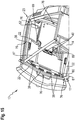
- Fig. 15 is a perspective view of the cabin 13 shown obliquely from below.
- the car roof 23 is designed as a prefabricated module which can be attached to the frame structure of the cab 13.
- the upper circumferentially formed frame parts 22 a plurality of attachment points 76 on which the preassembled cab roof 23 can be placed.
- Pre-assembled or prefabricated means that all necessary for the operation of the air treatment device 33 components have been arranged in an upstream production step between the upper shell 32 and the lower shell 33.
- the lower shell 33 is covered by a roof lining arranged thereon.
- the first air outlet openings 38 and the second air outlet openings 40 are installed exclusively in the cabin roof 23.
- a plurality of first air outlet openings 38 are arranged side by side in the region of the windshield 24.
- the second air outlet openings 40 arranged above the driver's seat 10 emit the second airflow 48 directed at the head area of the operator.
- a temperature difference perceivable by the operator without auxiliary means is obtained, in order to obtain a temperature distribution or temperature stratification which is pleasant for the operator.
- the admixture of supply air cooled by the cooling device 35 can be controlled by means of the flap 43.
- the flap 43 can be adjusted by a servomotor, which in turn can be controlled by an additional temperature sensor.
- At least one guide groove 81 is arranged, which serves for the section-wise positive reception of at least one tube 80 for the removal of condensate.
- the at least one guide groove 81 makes it possible to open the tube opening into an A-pillar 17 of the frame structure, in particular in the transition region from the car roof to lead in the A-pillar 17 kinking and compression-free.
- the pre-assembly is thereby simplified, being prevented during assembly of the prefabricated cabin roof 23 on the frame structure by the guide groove 81 that the hose 80 is bent when connecting to the A-pillar 17, which at least limits a drainage of the condensate.
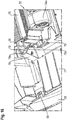
- FIG. 16 is a partial perspective view of the lower shell 32 shown from above.
- the air treatment device 33 has at least one connection 77, which is connected to a corresponding counterpart connection 78.
- the counter-circuit 78 supplies a cooled air flow to a roof cooling compartment 76 integrated in the cabin roof 23.
- the terminal 77 and the mating terminal 78 each have inclined contact surfaces 77a, 78a.
- the contact surfaces 77a and 78a are formed complementary to one another, so that the insertion of the air treatment device 33 at the same time leads to a sealing connection of the at least one connection 77 with the counterpart connection 78.
- the air treatment device 33 may also be designed with inclined contact surfaces in the region of the first air distribution channel 37, so that a seal can also be achieved during assembly of the air treatment device 33 here.
Landscapes
- Engineering & Computer Science (AREA)
- Mechanical Engineering (AREA)
- Chemical & Material Sciences (AREA)
- Combustion & Propulsion (AREA)
- Transportation (AREA)
- Physics & Mathematics (AREA)
- Thermal Sciences (AREA)
- Body Structure For Vehicles (AREA)
Abstract
Description
- Die vorliegende Erfindung betrifft eine Kabine für ein landwirtschaftliches Arbeitsfahrzeug gemäß dem Oberbegriff des Anspruches 1 sowie ein landwirtschaftliches Arbeitsfahrzeug mit einer Kabine.
- Kabinen für landwirtschaftliches Arbeitsfahrzeug, wie sie in der Land-, Forst oder Bauwirtschaft zum Einsatz kommen, stellen einen vollwertigen Arbeitsplatz dar, der von einer Bedienperson oftmals während eines gesamten Arbeitstages genutzt wird. Beispielhaft sind hier Traktoren, selbstfahrende Erntemaschinen wie Mähdrescher oder Feldhäcksler, Holzvollernter oder Radlader zu nennen. Da solche Arbeitsfahrzeuge unter verschiedensten klimatischen Umgebungsbedingen zum Einsatz kommen, sind die Kabinen mit einer Luftbehandlungsvorrichtung ausgestattet, die zum Kühlen und Erwärmen eines der Kabine zugeführten Frischluftstromes dient.
- Eine Kabine für ein Arbeitsfahrzeug gemäß dem Oberbegriff des Anspruches 1 ist aus der
EP 2 080 649 B1 bekannt. Die Kabine umfasst einen Boden und ein Kabinendach, zwischen denen, von einer Rahmenstruktur aufgenommen, eine Frontscheibe und Seitenscheiben angeordnet sind, die eine Rundumsicht der Bedienperson ermöglichen. Auf dem Boden der Kabine ist ein Fahrersitz angeordnet. In dem Kabinendach der Kabine ist eine Luftbehandlungsvorrichtung zum Kühlen und Erwärmen eines Frischluftstromes angeordnet, der mittels wenigstens eines Gebläses durch einen im Kabinendach angeordneten Ansaugkanal von außerhalb der Kabine zuführbar ist. Der Zusammenbau und die Montage des Kabinendaches erfolgt auf der Rahmenstruktur, wobei über Kopf gearbeitet werden muss, was unergonomisch ist. - Aufgabe der vorliegenden Erfindung ist es, eine Kabine für landwirtschaftliches Arbeitsfahrzeug bereitzustellen, welche die Nachteile des Standes der Technik vermeidet.
- Die vorstehende Aufgabe wird für eine Kabine erfindungsgemäß durch die Merkmale des Anspruches 1 sowie für ein landwirtschaftliches Arbeitsfahrzeug durch die Merkmale des Anspruches 8 gelöst.
- Vorteilhafte Weiterbildungen sind Gegenstand der Unteransprüche.
- Gemäß dem Anspruch 1 wird eine Kabine für ein landwirtschaftliches Arbeitsfahrzeug, umfassend einen Kabinenboden, einen darauf angeordneten, aus einer Rahmenstruktur bestehenden Kabinenkörper sowie ein Kabinendach, welches zwei oder mehr Schalen umfasst, vorgeschlagen. Um den Prozess der Montage der Kabine zu vereinfachen ist erfindungsgemäß vorgesehen, dass das Kabinendach als ein vorkonfektioniertes Modul ausgeführt ist, welches auf den Kabinenkörper aufsetzbar ist. Die Vorkonfektionierung bzw. Vormontage hat den Vorteil, dass alle Zusammenbau- und Installationsarbeiten, die das Kabinendach betreffen, vorab durchgeführt werden können. Eine zeitintensivere und aufwendigere Überkopfmontage, wie sie bisher im Stand der Technik üblich ist, entfällt hierdurch. Zudem lässt sich die Zahl der sichtbaren Verbindungselemente von Kabinendach und Rahmenstruktur zumindest reduzieren. Insbesondere im oberen rückwärtigen Bereich der Kabine lassen sich Verbindungselemente je nach Anwendungsbereich respektive Typ des Arbeitsfahrzeugs, auf welchem die Kabine zum Einsatz kommt, in dort vorgesehene Bauteile integrieren. So können bei einem beispielhaft als selbstfahrender Mähdrescher oder Feldhäcksler ausgeführten landwirtschaftlichen Arbeitsfahrzeug die Verbindungselemente im oberen rückwärtigen Bereich der Kabine durch eine Abdeckung auf der geschlossenen Rückwand verdeckt werden. Bei einem beispielsweise als Traktor ausgeführten landwirtschaftlichen Arbeitsfahrzeug lassen sich die Verbindungselemente im oberen rückwärtigen Bereich der Kabine durch die Abdeckung eines Wischermotors verdecken, der an der gläsernen Rückwand der Kabine montiert ist.
- Dabei kann die Rahmenstruktur des Kabinenkörpers zur Aufnahme des als Modul ausgeführten Kabinendaches von oben eingerichtet sein. Neben der Vereinfachung der Montage durch den Wegfall der Überkopfmontage gegenüber dem Stand der Technik hat die Ausführung des Kabinendaches als vormontiertes Modul den Vorteil, dass nach der Montage des Kabinendaches im Innenraum keine Verbindungselemente wie Schrauben oder dergleichen sichtbar sind.
- Hierzu kann die Rahmenstruktur umlaufend ausgebildete obere Rahmenteile aufweisen, welche mit Befestigungspunkten zur Fixierung des Kabinendaches versehen sind.
- Weiterhin kann zwischen den zumindest zwei Schalen des als vorkonfektioniertes Modul ausgeführten Kabinendachs eine Luftbehandlungsvorrichtung angeordnet sein, welche geneigte Anlageflächen aufweist, die in montierter Position mit komplementären Anlageflächen bündig abschließen. Das Einsetzten der Luftbehandlungsvorrichtung in die Unterschale führt zu einem formschlüssigen Anliegen der Anlageflächen der Luftbehandlungsvorrichtung an den komplementären Anlageflächen, wodurch eine Fixierung der Luftbehandlungsvorrichtung erreicht werden kann.
- Insbesondere kann die Luftbehandlungsvorrichtung jeweils zumindest einen Anschluss zur Zu- und Abführung eines Luftstromes aufweist, welche mit korrespondierenden Gegenanschlüssen im Kabinendach verbindbar sind, wobei jeweilige die Anschlüsse der Luftbehandlungsvorrichtung und die Gegenanschlüsse umgebende Rahmenelemente zur Anschlussebene geneigte komplementäre Anlageflächen aufweisen. Durch das bündige und formschlüssige Anliegen kann neben der Fixierung gleichzeitig eine Dichtfunktion durch die Luftbehandlungsvorrichtung selbst erreicht werden. Insbesondere kann einer der Gegenanschluss ein erster Luftverteilkanal sein.
- Die jeweiligen Anlageflächen können mit Dichtelementen versehen sein. Diese werden durch die Gewichtskraft der Luftbehandlungsvorrichtung gegeneinander gepresst, so dass es keiner zusätzlichen unterstützenden Mittel bedarf.
- Eine weitere Ausführungsform sieht vor, dass in zumindest einer der Schalen des Kabinendachs zumindest eine Führungsnut angeordnet ist, welche der abschnittsweise formschlüssigen Aufnahme wenigstens eines Schlauchs zur Abführung von Kondensat dient. Die zumindest eine Führungsnut dient dazu, den in eine A-Säule der Rahmenstruktur mündenden Schlauch insbesondere im Übergangsbereich vom Kabinendach in die A-Säule knick- und stauchungsfrei zu führen. Dadurch wird die Vormontage vereinfacht. Bei der Montage des vorkonfektionierten Kabinendaches auf der Rahmenstruktur wird durch die Führungsnut verhindert, dass der Schlauch beim Verbinden mit der A-Säule abgeknickt wird, was einen Abfluss des Kondensats zumindest einschränkt.
- Weiterhin wird die eingangs gestellte Aufgabe durch ein landwirtschaftliches Arbeitsfahrzeug mit einer Kabine gelöst, die nach einem der Ansprüche 1 bis 7 ausgeführt ist.
- Die vorliegende Erfindung wird nachstehend anhand von in den Zeichnungen dargestellten Ausführungsbeispielen näher erläutert.
- Es zeigen:
- Fig. 1
- ein als landwirtschaftlicher Traktor ausgebildetes Arbeitsfahrzeug;
- Fig. 2
- eine Ansicht eines Kabinendaches eines Arbeitsfahrzeuges von unten;
- Fig. 3
- eine Längsschnittansicht entlang der Linie A-A gemäß
Fig. 2 des Kabinendaches; - Fig. 4
- eine Teilansicht X gemäß
Fig. 2 auf eine Unterschale; - Fig. 5
- eine perspektivische Ansicht eines Ausschnitts B gemäß
Fig. 2 des Kabinendaches; - Fig. 6
- eine Teilschnittansicht des Kabinendaches entlang der Linie E-E gemäß
Fig. 2 mit einem Aufnahmeabschnitt für einen Luftfilter; - Fig. 7
- eine perspektivische Ansicht eines den Aufnahmeabschnitt verschließenden Abdeckelementes;
- Fig. 8
- eine Teilansicht des Kabinendaches von schräg hinten mit einem zu montierenden Filterschlauch;
- Fig. 9
- eine Teilansicht des Kabinendaches 23 von schräg hinten mit montiertem Filterschlauch;
- Fig. 10
- eine perspektivische Teilansicht D gemäß
Fig. 2 des Kabinendaches von schräg hinten mit einem Wandeinsatz; - Fig. 11
- eine perspektivische Teilansicht D gemäß
Fig. 2 des Kabinendaches von schräg hinten mit einem Wandeinsatz gemäß einer weiteren Ausführungsform; - Fig. 12
- eine perspektivische Teilansicht des Kabinendaches von schräg unten;
- Fig. 13
- eine Teilansicht des Kabinendaches im Längsschnitt entlang der Linie E-E gemäß
Fig. 2 ; - Fig. 14
- eine perspektivische Teilansicht des Kabinendaches von der Seite;
- Fig. 15
- eine perspektivische Ansicht der Kabine von schräg unten;
- Fig. 16
- eine perspektivische Teilansicht auf die Unterschale von oben.
- In der
Figur 1 ist ein als landwirtschaftlicher Traktor 1 ausgebildetes Arbeitsfahrzeug dargestellt, welches in Blockbauweise ausgebildet ist. Dabei ist ein Motorgehäuse 2 einer Brennkraftmaschine des Traktors 1 mit einem Getriebe- und Hinterachsgehäuse 3 verbunden. In seinem Frontbereich weist der Traktor 1 eine Vorderachse 4 auf, die über ein nicht näher dargestelltes Vorderachsgehäuse am Motorgehäuse 2 befestigt ist. Im Heckbereich des Traktors 1 gehen von dem Getriebe- und Hinterachsgehäuse 3 zwei Radachsen aus, von denen in der Darstellung nach derFigur 1 nur eine Radachse 5 sichtbar ist. Die Radachsen treiben dabei Hinterräder 6 an, die beidseitig des Traktors 1 über einen Teil ihres Außenumfangs von Kotflügeln 7 und 8 abgedeckt sind, wobei die Kotflügel 7 und 8 gemeinsam mit einem Fahrerstand 9 ausgebildet sein können. Auf diesem Fahrerstand 9, der gemeinsam mit den Kotflügeln 7 und 8 ausgebildet ist, sind unter anderem ein Fahrersitz 10, eine Lenkeinrichtung 11 sowie eine Anzeige- und Bedieneinheit 12 angeordnet. Es liegt im Rahmen der Erfindung, dass es sich bei dem Arbeitsfahrzeug auch um einen selbstfahrenden Mähdrescher oder Feldhäcksler sowie um ein sonstiges land-, forstwirtschaftliches oder kommunales Nutzfahrzeug mit einer Kabine handeln kann. - Eine Fahrerkabine 13 des Traktors 1 bildet mit dem Fahrerstand 9 eine Einheit, die gegenüber dem sie tragenden Getriebe- und Hinterachsgehäuse 3 über nicht näher dargestellte Elemente federnd bzw. schwingungsdämpfend gelagert ist. Daher wird von dem Fahrerstand 9 ein Kabinenboden 14 gebildet, und untere Rahmenteile 15 der Fahrerkabine 13 umschließen zum Teil den Kabinenboden 14 und sind in anderen Bereichen oberhalb der Kotflügel 7 und 8 geführt. Von den unteren Rahmenteilen 15 gehen im Frontbereich der Fahrerkabine 13 im Wesentlichen vertikal verlaufende A-Säulen 16 und 17 aus, zu denen beabstandet B-Säulen 18 und 19 und schließlich am Heck der Fahrerkabine 13 hintere Säulen 20 und 21 verlaufen.
- Die Säulen 16 bis 21 sind an ihren oberen Enden über obere Rahmenteile 22 miteinander verbunden, wobei diese oberen Rahmenteile 22 umlaufend ausgebildet sind und ein als vorkonfektioniertes Modul ausgeführtes Kabinendach 23 aufnehmen. Wie weiterhin aus der
Figur 1 hervorgeht, ist die Fahrerkabine 13 rundherum verglast, d. h., sie weist eine Frontscheibe 24 und von dieser durch Querrahmen abgetrennte, im Fußraum befindliche vordere Frontscheibenteile 25 auf. Weiterhin ist auf beiden Seiten der Fahrerkabine 1 jeweils eine verglaste Kabinentür 26 und 27 vorgesehen, die, wie aus der perspektivischen Darstellung hervorgeht, jeweils schwenkbar an der B-Säule 18 bzw. 19 gelagert ist und an die entsprechende A-Säule 16 bzw. 17 anschlägt. Hinter den verglasten Kabinentüren 26 und 27 befinden sich zwischen der jeweiligen B-Säule 18 bzw.19 und der entsprechenden hinteren Säule 20 bzw. 21 Seitenfenster 28 und 29. Schließlich ist die Fahrerkabine 13 auf ihrer Heckseite, also in dem zwischen den hinteren Säulen 20 und 21 liegenden Bereich durch eine Heckscheibe 30 verschlossen, die zur Verbesserung der Sicht auf im Heckbereich der Kabine 13 angebaute Arbeitsgeräte bis an den Kabinenboden 14 reichen kann. -
Fig. 2 zeigt das Kabinendach 23 in einer Ansicht von unten, wobei zur besseren Veranschaulichung eine das Kabinendach 23 begrenzende Oberschale 32 transparent dargestellt ist. - In
Fig. 3 ist eine Längsschnittansicht des Kabinendaches 23 entlang der Linie A-A gemäß derFig. 2 dargestellt. Das Kabinendach 23 umfasst zumindest zwei Schalen, eine Oberschale 31 und eine Unterschale 32. In der dargestellten Ausführungsform ist zwischen der Oberschale 31 und der Unterschale 32 eine Luftbehandlungsvorrichtung 33 angeordnet. Eine hiervon abweichende Anordnung einer Luftbehandlungsvorrichtung ist denkbar, beispielsweise im Bereich außerhalb des Kabinendaches 23. Die Luftbehandlungsvorrichtung 33 weist zumindest ein Gebläse 34a bzw. 34b, eine Kühlvorrichtung 35 sowie eine Heizvorrichtung 36 auf. Vorzugsweise sind zwei Gebläse 34a, 34b vorgesehen, die der Kühlvorrichtung 35 einen Zuluftstrom ZL zuführen.Fig. 3 zeigt eine Ansicht des Kabinendaches 23 von oben, wobei die Oberschale 31 transparent dargestellt ist. Der Zuluftstrom ZL wird, wie inFig. 3 angedeutet, durch einen Ansaugkanals 46 angesaugt und den Gebläsen 34a, 34b zugeführt. Der Zuluftstrom ZL durchströmt die Kühlvorrichtung 35 und gelangt im Anschluss zu der hierzu beabstandet angeordneten Heizvorrichtung 36. Zwischen der Kühlvorrichtung 35 und der Heizvorrichtung 36 ist ein erster Bypass 42 angeordnet. Der Bypass 42 weist ein als Klappe 43 ausgeführtes Strömungsbegrenzungselement auf. In einer einfacheren Ausführung des ersten Bypasses 42 kann der abzuzweigende Volumenstrom gekühlter Zuluft durch zumindest ein Strömungsbegrenzungselement begrenzbar sein, welches als Blende oder Drossel ausgebildet ist. Der nicht durch den ersten Bypass 42 abgezweigte Volumenstrom gekühlter Zuluft durchströmt die Heizvorrichtung 36. Der Heizvorrichtung 36 ist ein zweiter Bypass 44 nachgeordnet. Der zweite Bypass 44 ist als eine Klappe 45 ausgeführt. Der aus der Heizvorrichtung 36 austretende, am zweiten Bypass 44 vorbeigeführte Volumenstrom bildet einen ersten Luftstrom 47, welcher einem ersten Luftverteilkanal 37 zugeführt wird. Der erste Luftverteilkanal 37 weist einen im Wesentlichen U-förmigen Verlauf auf. Dabei verlaufen näherungsweise parallele Teilabschnitte des ersten Luftverteilkanals 37 zumindest abschnittsweise in Längsrichtung der Kabine 13 zwischen der jeweiligen A-Säule 16 bzw. 17 und der jeweiligen B-Säule 18 bzw.19 oder der entsprechenden hinteren Säule 20 bzw. 21. Ein quer verlaufender Teilabschnitt des ersten Luftverteilkanals 37 erstreckt sich im Bereich der Frontscheibe 24 im Wesentlichen über die Breite der Kabine 13. Der erste Luftverteilkanal 37 weist erste Luftaustrittsöffnungen 38 auf. Aus den ersten Luftaustrittsöffnungen 38 tritt der im Wesentlichen entlang der Frontscheibe 24 strömende, nach unten gerichtete erste Luftstrom 47 aus. - Der hinter der Kühlvorrichtung 35 durch den ersten Bypass 42 abgezweigte Teilvolumenstrom gelangt, unter Umgehung der Heizvorrichtung 36, in eine hinter der Heizvorrichtung 35 befindliche Mischzone 41. In diese Mischzone 41 wird ein von dem zweiten Bypass 44 abgezweigter Teilvolumenstrom des von der Heizvorrichtung 36 erwärmten Zuluftstromes ZL eingeleitet. Die beiden Teilvolumenströme bilden einen zweiten Luftstrom 48 der einem zweiten Luftverteilkanal 39 zugeführt wird. Der zweite Luftverteilkanal 39 weist zweite Luftaustrittsöffnungen 40 auf, die in das Innere der Kabine 13 münden. Aus den zweiten Luftaustrittsöffnungen 40 tritt der in Richtung des Fahrersitzes 10 gerichtete zweite Luftstrom 48 aus.
- Zwischen dem ersten Luftstrom 47 und dem zweiten Luftstrom 48 besteht eine Temperarturdifferenz, wobei der erste Luftstrom 47 eine höhere Temperatur aufweist, als der zweite Luftstrom 48. Dies hat den Effekt, dass der zweite Luftstrom 48 zum einen der Entfrostung zumindest der Frontscheibe 24 dienen kann sowie der Zuführung wärmer Luft im Bereich des Kabinenbodens 14 als im höher liegenden Bereich des Fahrersitzes 10. Bevorzugt liegt die Temperaturdifferenz zwischen dem zweiten Luftstrom 48 bei Austritt aus den zweiten Luftaustrittsöffnungen und dem ersten Luftstrom 47 bei Erreichen des Kabinenbodens 14 in einem Bereich, welcher im Allgemeinen durch eine Bedienperson ohne technische Hilfsmittel wahrnehmbar ist. Auf diese Weise wird eine Temperaturverteilung in der Kabine 13 erzielt, die von einer Bedienperson als besonders angenehm empfunden wird. Sowohl die Klappe 43 als auch die Klappe 45 können beispielsweise temperaturabhängig angesteuert werden, um die abgezweigten Teilvolumenströme, die zu dem zweiten Luftstrom 48 zusammengeführt werden, zu verändern.
- Durch den Ansaugkanal 46 wird von den Gebläsen 34a, 34b der Zuluftstrom ZL angesaugt, welcher zumindest einem als Luftfilter 49 ausgebildeten Filterelement zugeführt wird, wie in
Fig. 2 dargestellt. Der oder die Luftfilter 49 sind in Aufnahmeabschnitten 50 im Kabinendach 23 angeordnet. Die Luftfilter 49 sind als Taschenfilter ausgeführt. Anstelle der Taschenfilter sind auch Filterelemente der Kategorie 4 in die Aufnahmeabschnitte 50 einsetzbar, welche zur Anwendung kommen müssen, wenn mit dem Arbeitsfahrzeug 1 beispielsweise Spritzmittel ausgebracht werden sollen. Im Wesentlichen quer zur Frontscheibe 25 ist ein Umluftfilter 51 liegend angeordnet. Der Umluftfilter 51 filtriert aus der Kabine 13 angesaugte Luft, bevor diese erneut der Luftbehandlungsvorrichtung 33 als Umluft zugeführt wird. - Benachbart zu dem Ansaugkanal 46 ist eine Entlüftungsklappe 52 angeordnet, welche das Innere der Kabine 13 mit dem Ansaugkanal 46 strömungstechnisch verbindet. Die Entlüftungsklappe 52 ist nur einseitig betätigbar und öffnet bei einem im Inneren der Kabine 13 schlagartig auftretenden Überdruck, welcher durch das Zuschlagen der Kabinentür 26 hervorgerufen wird. Der durch die Entlüftungsklappe 52 entweichende Luftstrom gelangt durch den Ansaugkanal 46 zu den Luftfiltern 49. Die schlagartig auftretende Luftdruckdifferenz versetzt die Luftfilter 49 in Bewegung bzw. Schwingung. Auf diese Weise lässt sich ein Reinigungseffekt erzielen, indem an den Wänden der Luftfilter 49 abgelagerte Partikel durch die Bewegung abgelöst werden. Zugleich dient der Ansaugkanal 46 der Entlüftung.
- Weiterhin zeigt die Darstellung in
Fig. 2 , dass die Oberschale 31 gegenüber der transparent dargestellten Unterschale 32 an einer Seite einen sich über die Breite des Kabinendaches 23 erstreckenden flächigen Überstand 74 aufweist. Der Überstand 74 stützt sich gegenüber der Unterschale 32 durch zumindest zwei beabstandet zueinander angeordnete Profilelemente 73 an dieser ab. Zur Verringerung des Gewichts bei gleichzeitiger Erhaltung oder Verbesserung der Stabilität sind die Profilelemente 73 im Wesentlichen tetraederförmig oder als 3D-Rippen ausgeführt. - Aufgrund der nur einseitigen Ansaugung des Zuluftstromes ZL wird von dem Gebläse 34a, welches dem Ansaugkanal 46 näherliegend angeordnet ist, anteilig mehr kalte Zuluft zugeführt, als dem zu dem Ansaugkanal 46 weiter beabstandeten Gebläse 34b. Um eine homogene Aufteilung des aus den ersten Luftaustrittsöffnungen 38 ausströmenden ersten Luftstromes 47 zu erreichen, sind zumindest in dem ersten Luftverteilkanal 37 Mittel zur strömungstechnischen Beeinflussung des ersten Luftstroms 47 vorgesehen, was in den
Fig. 4 und 5 dargestellt ist. Dabei zeigt die Darstellung inFig. 4 eine Detailansicht X gemäßFig. 2 . InFig. 5 ist ein Ausschnitt B gemäßFig. 2 dargestellt. Bei den Mitteln handelt es sich um Rippen 53, Prallwände 54, Winkel der Prallwände 54 bzw. der Seitenwände des ersten Luftverteilkanals 37 oder sonstige das Strömungsverhalten beeinflussende Bauteile wie ein teilweise offenes Gehäuse 55, welches die erste Luftaustrittsöffnung 38 abschnittsweise umschließt. Ebenso kommt eine Variation einzelner Querschnitte des ersten Luftverteilkanal 37 zur Strömungsbeeinflussung zum Tragen. - In
Fig. 6 ist eine Teilschnittansicht des Kabinendaches 23 entlang der Linie C-C gemäßFig. 2 dargestellt, welche den Aufnahmeabschnitt 50 für einen der Luftfilter 49 zeigt. Der Aufnahmeabschnitt 50 erstreckt sich im Wesentlichen waagerecht zwischen der Oberschale 31 und der Unterschale 32. -
Fig. 7 zeigt ein Abdeckelement 56, welches den Aufnahmeabschnitt 50 verschließt. Das Abdeckelement 56 ist lösbar an einer zwischen der Oberschale 31 und der Unterschale 32 ausgebildeten umlaufenden Seitenwand 57 angeordnet. In montierter Position schließt das Abdeckelement 56 bündig mit der umlaufenden Seitenwand 57 ab. Das Abdeckelement 56 weist zu seiner Befestigung an der Oberschale 31 Befestigungsabschnitte 59 auf, welche ein Hochschwenken des Abdeckelementes 56 in Richtung der Oberschale 31 ermöglichen. Zur lösbaren Verbindung des Abdeckelementes 56 mit der Unterschale 32 sind Befestigungselemente 60 vorgesehen. Das Abdeckelement 56 weist auf seiner Innenseite zumindest zwei Paar Stege 58a, 58b auf, die sich abschnittsweise in Richtung des Aufnahmeabschnittes 50 erstrecken. Die Stege 58a, 58b eines Paares weisen unterschiedliche Längen auf, welches der nachgewölbten Kontur des Abdeckelementes 56 geschuldet ist. Die Länge der Stege 58a, 58b ist so bemessen, dass bei in den Aufnahmeabschnitt 50 eingebautem Luftfilter 49 sich die Stege 58a, 58b am Rahmen des Luftfilters 49 abstützen und diesen in dem Aufnahmeabschnitt 50 fixieren, wobei zugleich das Abdeckelement 56 bündig mit der umlaufenden Seitenwand 57 abschließt. Wurde das Filterelement 49 nicht korrekt in den Aufnahmeabschnitt 50 eingesetzt, führt das dazu, dass das Abdeckelement 56 nicht bündig mit der umlaufenden Seitenwand 57 abschließen kann. - In den
Fig. 8 und 9 ist eine Teilansicht des Kabinendaches 23 von schräg hinten dargestellt. An der umlaufenden Seitenwand 57 ist ein Dachseitenelement 61 schwenkbar angelenkt, welches sich aus einer zur Oberschale 31 im Wesentlichen parallelen Position in eine unter einem Winkel zur Oberschale 31 geneigte Position überführen lässt. Letztere geneigte Position des Dachseitenelementes 61 ist inFig. 8 dargestellt. An der Rückseite des Kabinendaches 23 weist die umlaufende Seitenwand 57 einen Abschnitt 62 mit Luftzufuhröffnungen 62a auf, an welchen sich der Ansaugkanal 46 anschließt. An dem Abschnitt 62 ist ein zur Oberseite des Kabinendaches 23 hin offen ausgeführtes Aufnahmeelement 63 angeordnet. In das Aufnahmeelement 63 ist ein endseitig an einem Filterschlauch 65 angeordnetes flanschförmiges Anschlusselement 64 von oben formschlüssig einführbar. Der außenseitig an der Kabine 13 angeordnete Filterschlauch 65 dient der Vorfiltration von großen Schmutzpartikeln aus der angesaugten Luft, wodurch die Standzeit der Luftfilter 49 verlängert wird. Hierzu ist die formschlüssige Verbindung zwischen dem Aufnahmeelement 63 und dem Anschlusselement 64 als Schwalbenschwanzverbindung ausgebildet. Die Bedienperson muss für das Anschließen bzw. das Lösen des Filterschlauches 65 lediglich das Dachseitenelement 61 hochschwenken und kann anschließend das Anschlusselement 64 in vertikaler Richtung in das Aufnahmeelement 63 einführen bzw. hinausschieben. Das heruntergeschwenkte Dachseitenelement 61 verhindert in montierter Position des Filterschlauches 65 das Hinausgleiten des Anschlusselementes 64 aus dem Aufnahmeelement 63. - In den
Fig. 10 und 11 ist eine perspektivische Teilansicht D gemäßFig. 2 des Kabinendaches 23 von hinten dargestellt. In der umlaufenden Seitenwand 57 ist eine Aussparung 66 angeordnet. Die Aussparung 66 ist für Kabinendächer 23 bzw. Kabinen 13, die für unterschiedliche Arbeitsfahrzeuge 1, wie zum Bespiel Traktoren, selbstfahrende Mähdrescher oder Feldhäcksler, verwendet werden sollen, einheitlich dimensioniert. In die Aussparung 66 wird ein mit zumindest einer Durchtrittsöffnung 68 versehener Wandeinsatz 67 eingebracht, welcher die Aussparung 66 verschließt. InFig. 10 ist dabei eine erste Ausführungsform des Wandeinsatzes 67 mit mehreren Durchtrittsöffnungen 68 dargestellt. InFig. 11 ist eine zweite Ausführungsform des Wandeinsatzes 67 mit nur einer Durchtrittsöffnung 68 dargestellt. Die Anzahl und Ausgestaltung der Durchtrittsöffnungen 68 des jeweiligen Wandeinsatzes 67 hängt vom jeweiligen Typ des Arbeitsfahrzeuges 1 ab. - In
Fig. 12 ist eine perspektivische Teilansicht des Kabinendaches 23 von unten dargestellt. Zwischen der Unterschale 32 und der Oberschale 31 sind mehrere hohlzylindrische Abschnitte 69 mit geschlossener Mantelfläche angeordnet. Die hohlzylindrischen Abschnitte 69 können dabei identische oder voneinander abweichende Querschnittsformen aufweisen. Eine in die Unterschale 32 mündende offen ausgeführte Grundfläche 70 des jeweiligen hohlzylindrischen Abschnittes 69 ist durch eine nicht dargestellte Lautsprechermembrane dichtend verschließbar. Die jeweils durch die Lautsprechermembrane verschlossenen hohlzylindrischen Abschnitte 69 bilden einen Resonanzkörper aus. Die Volumina der hohlzylindrischen Abschnitte 69 können jeweils durch ein Volumenbegrenzungselement veränderbar sein. Weiterhin zeigt die Darstellung inFig. 12 , dass das Innere der Kabine 13 durch einen im Kabinendach 23 angeordneten Entlüftungskanal 71 mit der Umgebung strömungstechnisch permanent verbunden ist. Der Entlüftungskanal 71 weist einen Abschnitt 72 mit einem im Wesentlichen U-förmigen Verlauf auf, was in der Teilansicht des Kabinendaches 23 im Längsschnitt entlang der Linie E-E gemäßFig. 2 inFig. 13 näher dargestellt ist. - Die Darstellung in
Fig. 14 zeigt eine perspektivische Teilansicht des Kabinendaches 23 von der Seite. Die Aufnahmeabschnitte 50 sind ohne eingesetzte Luftfilter 49 dargestellt. Durch den freien vorderen Aufnahmeabschnitt 50 lässt sich der Umluftfilter 51 nach außen herausziehen. Diese Anordnung hat den Vorteil, dass der Umluftfilter 51 nicht, wie im Stand der Technik üblich, nach innen in die Kabine entleert werden muss, sondern nach außen. Durch das Entnehmen des liegend angeordneten Umluftfilters 51 nach außen wird das Herausrieseln von Partikeln, die der Filter aufgenommen hat, vermieden. - Benachbart zu den Gebläsen 34a und 34b ist ein Zusatzgebläse 75 angeordnet. Das Zusatzgebläse 75 dient dazu, den bei einem Austausch der als Taschenfilter ausgeführten Luftfilter 49 durch Filterelemente, beispielsweise der Kategorie 4 oder darunterliegend, die von den Aufnahmeabschnitten 50 aufgenommen und dem Abdeckelement 56 in gleicher Weise fixiert werden, erhöhten Zuluftbedarf auszugleichen. Hierzu sind die unterschiedlichen Filterelemente als Module ausgebildet, die an die Aufnahmeabschnitte 50 angepasst sind, so dass eine einfache Auswechselbarkeit gegeben ist.
- In
Fig. 15 ist eine perspektivische Ansicht der Kabine 13 von schräg unten dargestellt. Das Kabinendach 23 ist als vorkonfektioniertes Modul ausgeführt, welches an der Rahmenstruktur der Kabine 13 anbringbar ist. Hierzu weisen die oberen umlaufend ausgebildeten Rahmenteile 22 mehrere Befestigungspunkte 76 auf, auf denen das vormontierte Kabinendach 23 aufsetzbar ist. Vormontiert bzw. vorkonfektioniert bedeutet, dass alle für den Betrieb der Luftbehandlungsvorrichtung 33 notwendigen Komponenten in einem vorgelagerten Fertigungsschritt zwischen der Oberschale 32 und der Unterschale 33 angeordnet worden sind. Die Unterschale 33 wird durch einen daran angeordneten Dachhimmel verkleidet. - Wie insbesondere aus der
Fig. 15 zu entnehmen ist, sind die ersten Luftaustrittsöffnungen 38 und die zweiten Luftaustrittsöffnungen 40 ausschließlich im Kabinendach 23 verbaut. Dabei sind im Bereich der Frontscheibe 24 mehrere erste Luftaustrittsöffnungen 38 nebeneinander angeordnet. Diese geben den von oben nach unten gerichteten ersten Luftstrom 47 ab, der im Wesentlichen entlang der Fronscheibe 24 zum Kabinenboden 14 strömt, das heißt in den Fußbereich der Bedienperson strömt. Die oberhalb des Fahrersitzes 10 angeordneten zweiten Luftaustrittsöffnungen 40 geben den auf den Kopfbereich der Bedienperson gerichteten zweiten Luftstrom 48 ab. Wie bereits weiter oben ausgeführt, besteht zwischen dem wärmeren ersten Luftstrom 47 und dem kühleren zweiten Luftstrom 48 eine von der Bedienperson ohne Hilfsmittel wahrnehmbare Temperaturdifferenz, um eine für das Empfinden der Bedienperson angenehme Temperaturverteilung bzw. Temperaturschichtung zu erhalten. - Zur Beeinflussung der Temperaturverteilung lässt sich die Beimischung von durch die Kühlvorrichtung 35 gekühlter Zuluft mittels der Klappe 43 steuern. Die Klappe 43 kann durch einen Stellmotor verstellt werden, der wiederum durch einen zusätzlichen Temperatursensor ansteuerbar sein kann.
- In der Unterschale oder der Oberschale des Kabinendachs ist zumindest eine Führungsnut 81 angeordnet, welche der abschnittsweisen formschlüssigen Aufnahme zumindest eines Schlauchs 80 zur Abführung von Kondensat dient. Die zumindest eine Führungsnut 81 ermöglicht es, den in eine A-Säule 17 der Rahmenstruktur mündenden Schlauch insbesondere im Übergangsbereich von dem Kabinendach in die A-Säule 17 knick- und stauchungsfrei zu führen. So wird dadurch die Vormontage vereinfacht, wobei bei der Montage des vorkonfektionierten Kabinendaches 23 auf der Rahmenstruktur durch die Führungsnut 81 verhindert wird, dass der Schlauch 80 beim Verbinden mit der A-Säule 17 abgeknickt wird, was einen Abfluss des Kondensats zumindest einschränkt.
- In
Fig. 16 ist eine perspektivische Teilansicht auf die Unterschale 32 von oben dargestellt. Die Luftbehandlungsvorrichtung 33 weist zumindest einen Anschluss 77 auf, der mit einem korrespondierenden Gegenanschluss 78 verbunden ist. Der Gegenschluss 78 führt einen gekühlten Luftstrom einem in das Kabinendach 23 integrierten Dachkühlfach 76 zu. Der Anschluss 77 als auch der Gegenanschluss 78 weisen jeweils geneigte Anlageflächen 77a, 78a auf. Die Anlageflächen 77a und 78a sind zueinander komplementär ausgebildet, so dass das Einsetzen der Luftbehandlungsvorrichtung 33 zugleich zu einer dichtenden Verbindung des zumindest einen Anschlusses 77 mit dem Gegenanschluss 78 führt. Die Luftbehandlungsvorrichtung 33 kann im Bereich des ersten Luftverteilkanals 37 ebenfalls mit geneigten Anlageflächen ausgeführt sein, so dass auch hier eine Abdichtung bei der Montage der Luftbehandlungsvorrichtung 33 erreicht werden kann.Bezugszeichenliste 1 Traktor 30 Heckscheibe 2 Motorgehäuse 31 Oberschale 3 Getriebe- und Hinterachsgehäuse 32 Unterschale 4 Vorderachse 33 Luftbehandlungsvorrichtung 5 Radachse 34a Gebläse 6 Hinterrad 34b Gebläse 7 Kotflügel 35 Kühlvorrichtung 8 Kotflügel 36 Heizvorrichtung 9 Fahrerstand 37 Erster Luftverteilkanal 10 Fahrersitz 38 Erste Luftaustrittsöffnung 11 Lenkeinrichtung 39 Zweiter Luftverteilkanal 12 Bedieneinheit 40 Zweite Luftaustrittsöffnung 13 Fahrerkabine 41 Mischzone 14 Kabinenboden 42 Erster Bypass 15 Rahmenteil 43 Klappe 16 A-Säule 44 Zweiter Bypass 17 A-Säule 45 Klappe 18 B-Säule 46 Ansaugkanal 19 B-Säule 47 Erster Luftstrom 20 Hintere Säule 48 Zweiter Luftstrom 21 Hintere Säule 49 Luftfilter 22 Rahmenteil 50 Aufnahmeabschnitt 23 Kabinendach 51 Umluftfilter 24 Frontscheibe 52 Entlüftungsklappe 25 Frontscheibenteil 53 Rippe 26 Kabinentür 54 Prallwand 27 Kabinentür 55 Gehäuse 28 Seitenfenster 56 Abdeckelement 29 Seitenfenster 57 Seitenwand 58a Steg ZL Zuluftstrom 58b Steg 59 Befestigungsabschnitt 60 Befestigungselement 61 Dachseitenelement 62 Abschnitt 63 Aufnahmeelement 64 Anschlusselement 65 Filterschlauch 66 Aussparung 67 Wandeinsatz 68 Durchtrittsöffnung 69 Hohlzylindrischer Abschnitt 70 Grundfläche von 69 71 Entlüftungskanal 72 U-förmiger Abschnitt 73 Profilelement 74 Überstand 75 Zusatzgebläse 76 Befestigungspunkt 77 Dachkühlfach 78 Anschluss 78a Anlagefläche 79 Gegenanschluss 79a Anlagefläche 80 Schlauch 81 Führungsnut
Claims (8)
- Kabine (13) für ein landwirtschaftliches Arbeitsfahrzeug (1), umfassend einen Kabinenboden (14), einen darauf angeordneten, aus einer Rahmenstruktur bestehenden Kabinenkörper sowie ein Kabinendach (23), welches zumindest zwei Schalen (31, 32) umfasst, dadurch gekennzeichnet, dass das Kabinendach (23) als ein vorkonfektioniertes Modul ausgeführt ist, welches auf den Kabinenkörper aufsetzbar ist.
- Kabine (13) nach Anspruch 1, dadurch gekennzeichnet, dass die Rahmenstruktur des Kabinenkörpers zur Aufnahme des als Modul ausgeführten Kabinendaches (23) von oben eingerichtet ist.
- Kabine (13) nach Anspruch 2, dadurch gekennzeichnet, dass die Rahmenstruktur umlaufend ausgebildete obere Rahmenteile (22) aufweist, welche mit Befestigungspunkten (75) zur Fixierung des Kabinendaches (23) versehen sind.
- Kabine (13) nach einem der vorangehenden Ansprüche, dadurch gekennzeichnet, dass zwischen den zumindest zwei Schalen (31, 32) des als vorkonfektioniertes Modul ausgeführten Kabinendachs (23) eine Luftbehandlungsvorrichtung (33) angeordnet ist, welche geneigte Anlageflächen (78a) aufweist, die in montierter Position mit komplementären Anlageflächen (79a) bündig abschließen.
- Kabine (13) nach Anspruch 4, dadurch gekennzeichnet, dass die Luftbehandlungsvorrichtung (33) jeweils zumindest einen Anschluss zur Zu- und Abführung eines Luftstromes aufweist, welche mit korrespondierenden Gegenanschlüssen im Kabinendach (23) verbindbar sind, wobei jeweilige die Anschlüsse der Luftbehandlungsvorrichtung (33) und die Gegenanschlüsse umgebende Rahmenelemente zur Anschlussebene geneigte komplementäre Anlageflächen aufweisen.
- Kabine (13) nach einem der Ansprüche 4 oder 5, dadurch gekennzeichnet, dass die Anlageflächen (78a, 79a) mit Dichtelementen versehen sind.
- Kabine (13) nach einem der vorangehenden Ansprüche, dadurch gekennzeichnet, dass in zumindest einer der Schalen (31, 32) des Kabinendachs (23) wenigstens eine Führungsnut (81) angeordnet ist, welche der abschnittsweise formschlüssigen Aufnahme zumindest eines Schlauchs (80) zur Abführung von Kondensat dient.
- Landwirtschaftliches Arbeitsfahrzeug (1) mit einer Kabine (13), dadurch gekennzeichnet, dass die Kabine (13) nach einem der Ansprüche 1 bis 7 ausgeführt ist.
Applications Claiming Priority (1)
| Application Number | Priority Date | Filing Date | Title |
|---|---|---|---|
| DE102017115126.5A DE102017115126A1 (de) | 2017-07-06 | 2017-07-06 | Kabine für ein landwirtschaftliches Arbeitsfahrzeug |
Publications (2)
| Publication Number | Publication Date |
|---|---|
| EP3424805A1 true EP3424805A1 (de) | 2019-01-09 |
| EP3424805B1 EP3424805B1 (de) | 2022-09-28 |
Family
ID=61768184
Family Applications (1)
| Application Number | Title | Priority Date | Filing Date |
|---|---|---|---|
| EP18163872.7A Active EP3424805B1 (de) | 2017-07-06 | 2018-03-26 | Kabine für ein landwirtschaftliches arbeitsfahrzeug |
Country Status (3)
| Country | Link |
|---|---|
| US (1) | US10604190B2 (de) |
| EP (1) | EP3424805B1 (de) |
| DE (1) | DE102017115126A1 (de) |
Families Citing this family (2)
| Publication number | Priority date | Publication date | Assignee | Title |
|---|---|---|---|---|
| DE102018206111A1 (de) | 2018-04-20 | 2019-10-24 | Deere & Company | Dachstruktur |
| USD976967S1 (en) * | 2020-11-19 | 2023-01-31 | Caterpillar Sarl | Cab roof |
Citations (4)
| Publication number | Priority date | Publication date | Assignee | Title |
|---|---|---|---|---|
| EP0900718A2 (de) * | 1997-09-09 | 1999-03-10 | New Holland Belgium N.V. | Kabinendach für Getreide- Mähdrescher |
| DE60309525T2 (de) * | 2002-03-05 | 2007-10-04 | Société Nouvelle de Climatisation | Dachklimaanlage |
| EP2080649B1 (de) | 2008-01-18 | 2013-05-22 | CLAAS Selbstfahrende Erntemaschinen GmbH | Selbstfahrende Arbeitsmaschine mit einer Fahrzeugkabine |
| JP2014069617A (ja) * | 2012-09-27 | 2014-04-21 | Kubota Corp | 作業車 |
Family Cites Families (9)
| Publication number | Priority date | Publication date | Assignee | Title |
|---|---|---|---|---|
| US4641502A (en) * | 1985-01-09 | 1987-02-10 | The Duo-Therm Corporation | Roof mount air conditioner |
| US6178612B1 (en) * | 1998-10-08 | 2001-01-30 | Trp, Inc. | Method of converting a truck sleeper cab to a day cab |
| US6279978B1 (en) * | 1999-10-05 | 2001-08-28 | Deere & Company | Work vehicle roof structure |
| DE10118344A1 (de) * | 2001-04-12 | 2002-10-17 | Daimler Chrysler Ag | Modular aufgebaute Fahrerhaus-Baureihe für Lastkraftwagen |
| US6719361B1 (en) * | 2002-10-29 | 2004-04-13 | Mack Trucks, Inc. | Truck sleeper cab to day cab conversion kit assembly |
| US6780097B2 (en) * | 2003-01-29 | 2004-08-24 | Deere & Company | Two piece vehicle roof structure having an integrated HVAC system |
| US6883860B1 (en) * | 2003-12-02 | 2005-04-26 | East Side Heavy Truck Collision | Kit and method for truck cab conversion |
| US7334834B2 (en) * | 2006-03-09 | 2008-02-26 | Deere & Company | Tractor cab roof with integral HVAC air ducts |
| US9550407B2 (en) * | 2015-10-20 | 2017-01-24 | Caterpillar Inc. | HVAC integrated roof for operator cabs |
-
2017
- 2017-07-06 DE DE102017115126.5A patent/DE102017115126A1/de not_active Withdrawn
-
2018
- 2018-03-26 EP EP18163872.7A patent/EP3424805B1/de active Active
- 2018-05-15 US US15/980,089 patent/US10604190B2/en active Active
Patent Citations (4)
| Publication number | Priority date | Publication date | Assignee | Title |
|---|---|---|---|---|
| EP0900718A2 (de) * | 1997-09-09 | 1999-03-10 | New Holland Belgium N.V. | Kabinendach für Getreide- Mähdrescher |
| DE60309525T2 (de) * | 2002-03-05 | 2007-10-04 | Société Nouvelle de Climatisation | Dachklimaanlage |
| EP2080649B1 (de) | 2008-01-18 | 2013-05-22 | CLAAS Selbstfahrende Erntemaschinen GmbH | Selbstfahrende Arbeitsmaschine mit einer Fahrzeugkabine |
| JP2014069617A (ja) * | 2012-09-27 | 2014-04-21 | Kubota Corp | 作業車 |
Also Published As
| Publication number | Publication date |
|---|---|
| US20190009826A1 (en) | 2019-01-10 |
| DE102017115126A1 (de) | 2019-01-10 |
| US10604190B2 (en) | 2020-03-31 |
| EP3424805B1 (de) | 2022-09-28 |
Similar Documents
| Publication | Publication Date | Title |
|---|---|---|
| DE19628089C2 (de) | Belüftungseinrichtung für eine Fahrzeugkabine und Filtergehäuse | |
| DE10004751A1 (de) | Integriertes HVAC-System für Kraftfahrzeuge | |
| DE10037384A1 (de) | Heizungs- und Klimaanlage für ein Kraftfahrzeug | |
| EP2921327B1 (de) | Fahrerkabine einer land- oder bauwirtschaftlich nutzbaren Arbeitsmaschine | |
| DE102006009805B4 (de) | Kabine für Arbeitsfahrzeug | |
| EP3556585B1 (de) | Dachstruktur und kabine | |
| EP1228907B1 (de) | Klimagerät für ein Kraftfahrzeug | |
| DE10047731B4 (de) | Seitenwand für einen Personenkraftwagen | |
| EP3424805B1 (de) | Kabine für ein landwirtschaftliches arbeitsfahrzeug | |
| DE102005006250B3 (de) | Fahrzeugkarosserie eines Kraftwagens | |
| DE3901658C2 (de) | ||
| EP1291266A1 (de) | Hybridträger für ein Kraftfahrzeug | |
| EP3424759B1 (de) | Kabinendach einer kabine für ein landwirtschaftliches arbeitsfahrzeug | |
| EP1288035B1 (de) | Luftfiltersystem für Fahrzeugkabinen | |
| EP0934841B1 (de) | Sonnenblende für ein Kraftfahrzeug | |
| DE10347847B3 (de) | Kraftwagenkarosserie mit zentraler Tragsäule | |
| DE4435292C2 (de) | Klimagerät | |
| DE602004005988T2 (de) | Trägerstruktur für das Armaturenbrett eines Kraftfahrzeugs | |
| EP3862229B1 (de) | Nutzfahrzeug mit luftansaugkanal und aussenabdeckung | |
| EP3424760A1 (de) | Kabine für ein landwirtschaftliches arbeitsfahrzeug | |
| EP0773124B1 (de) | Fahrzeugkabine | |
| DE69112734T2 (de) | Gebläse für Heizungs- und/oder Klimaanlagen für Kraftfahrzeuge und Einrichtung ausgerüstet mit zwei solchen Gebläsen. | |
| EP1522437A1 (de) | Luftversorgungseinrichtung zur Klimatisierung eines Fahrzeuginnenraums eines Fahrzeugs, insbesondere eines Nutzfahrzeuges | |
| DE102007062158A1 (de) | Fahrzeugstirnwand sowie Luftansaugung für Fahrzeuge | |
| DE102006018905B4 (de) | Luftleitungsanordnung und Anwendung einer Matte |
Legal Events
| Date | Code | Title | Description |
|---|---|---|---|
| PUAI | Public reference made under article 153(3) epc to a published international application that has entered the european phase |
Free format text: ORIGINAL CODE: 0009012 |
|
| STAA | Information on the status of an ep patent application or granted ep patent |
Free format text: STATUS: THE APPLICATION HAS BEEN PUBLISHED |
|
| AK | Designated contracting states |
Kind code of ref document: A1 Designated state(s): AL AT BE BG CH CY CZ DE DK EE ES FI FR GB GR HR HU IE IS IT LI LT LU LV MC MK MT NL NO PL PT RO RS SE SI SK SM TR |
|
| AX | Request for extension of the european patent |
Extension state: BA ME |
|
| STAA | Information on the status of an ep patent application or granted ep patent |
Free format text: STATUS: REQUEST FOR EXAMINATION WAS MADE |
|
| 17P | Request for examination filed |
Effective date: 20190709 |
|
| RBV | Designated contracting states (corrected) |
Designated state(s): AL AT BE BG CH CY CZ DE DK EE ES FI FR GB GR HR HU IE IS IT LI LT LU LV MC MK MT NL NO PL PT RO RS SE SI SK SM TR |
|
| STAA | Information on the status of an ep patent application or granted ep patent |
Free format text: STATUS: EXAMINATION IS IN PROGRESS |
|
| 17Q | First examination report despatched |
Effective date: 20200406 |
|
| GRAP | Despatch of communication of intention to grant a patent |
Free format text: ORIGINAL CODE: EPIDOSNIGR1 |
|
| STAA | Information on the status of an ep patent application or granted ep patent |
Free format text: STATUS: GRANT OF PATENT IS INTENDED |
|
| RIC1 | Information provided on ipc code assigned before grant |
Ipc: B60H 1/00 20060101ALN20220420BHEP Ipc: B62D 33/06 20060101AFI20220420BHEP |
|
| INTG | Intention to grant announced |
Effective date: 20220512 |
|
| GRAS | Grant fee paid |
Free format text: ORIGINAL CODE: EPIDOSNIGR3 |
|
| GRAA | (expected) grant |
Free format text: ORIGINAL CODE: 0009210 |
|
| STAA | Information on the status of an ep patent application or granted ep patent |
Free format text: STATUS: THE PATENT HAS BEEN GRANTED |
|
| AK | Designated contracting states |
Kind code of ref document: B1 Designated state(s): AL AT BE BG CH CY CZ DE DK EE ES FI FR GB GR HR HU IE IS IT LI LT LU LV MC MK MT NL NO PL PT RO RS SE SI SK SM TR |
|
| REG | Reference to a national code |
Ref country code: GB Ref legal event code: FG4D Free format text: NOT ENGLISH |
|
| REG | Reference to a national code |
Ref country code: CH Ref legal event code: EP |
|
| REG | Reference to a national code |
Ref country code: DE Ref legal event code: R096 Ref document number: 502018010697 Country of ref document: DE |
|
| REG | Reference to a national code |
Ref country code: AT Ref legal event code: REF Ref document number: 1521084 Country of ref document: AT Kind code of ref document: T Effective date: 20221015 |
|
| REG | Reference to a national code |
Ref country code: IE Ref legal event code: FG4D Free format text: LANGUAGE OF EP DOCUMENT: GERMAN |
|
| REG | Reference to a national code |
Ref country code: LT Ref legal event code: MG9D |
|
| PG25 | Lapsed in a contracting state [announced via postgrant information from national office to epo] |
Ref country code: SE Free format text: LAPSE BECAUSE OF FAILURE TO SUBMIT A TRANSLATION OF THE DESCRIPTION OR TO PAY THE FEE WITHIN THE PRESCRIBED TIME-LIMIT Effective date: 20220928 Ref country code: RS Free format text: LAPSE BECAUSE OF FAILURE TO SUBMIT A TRANSLATION OF THE DESCRIPTION OR TO PAY THE FEE WITHIN THE PRESCRIBED TIME-LIMIT Effective date: 20220928 Ref country code: NO Free format text: LAPSE BECAUSE OF FAILURE TO SUBMIT A TRANSLATION OF THE DESCRIPTION OR TO PAY THE FEE WITHIN THE PRESCRIBED TIME-LIMIT Effective date: 20221228 Ref country code: LV Free format text: LAPSE BECAUSE OF FAILURE TO SUBMIT A TRANSLATION OF THE DESCRIPTION OR TO PAY THE FEE WITHIN THE PRESCRIBED TIME-LIMIT Effective date: 20220928 Ref country code: LT Free format text: LAPSE BECAUSE OF FAILURE TO SUBMIT A TRANSLATION OF THE DESCRIPTION OR TO PAY THE FEE WITHIN THE PRESCRIBED TIME-LIMIT Effective date: 20220928 Ref country code: FI Free format text: LAPSE BECAUSE OF FAILURE TO SUBMIT A TRANSLATION OF THE DESCRIPTION OR TO PAY THE FEE WITHIN THE PRESCRIBED TIME-LIMIT Effective date: 20220928 |
|
| REG | Reference to a national code |
Ref country code: NL Ref legal event code: MP Effective date: 20220928 |
|
| PG25 | Lapsed in a contracting state [announced via postgrant information from national office to epo] |
Ref country code: HR Free format text: LAPSE BECAUSE OF FAILURE TO SUBMIT A TRANSLATION OF THE DESCRIPTION OR TO PAY THE FEE WITHIN THE PRESCRIBED TIME-LIMIT Effective date: 20220928 Ref country code: GR Free format text: LAPSE BECAUSE OF FAILURE TO SUBMIT A TRANSLATION OF THE DESCRIPTION OR TO PAY THE FEE WITHIN THE PRESCRIBED TIME-LIMIT Effective date: 20221229 |
|
| PG25 | Lapsed in a contracting state [announced via postgrant information from national office to epo] |
Ref country code: SM Free format text: LAPSE BECAUSE OF FAILURE TO SUBMIT A TRANSLATION OF THE DESCRIPTION OR TO PAY THE FEE WITHIN THE PRESCRIBED TIME-LIMIT Effective date: 20220928 Ref country code: RO Free format text: LAPSE BECAUSE OF FAILURE TO SUBMIT A TRANSLATION OF THE DESCRIPTION OR TO PAY THE FEE WITHIN THE PRESCRIBED TIME-LIMIT Effective date: 20220928 Ref country code: PT Free format text: LAPSE BECAUSE OF FAILURE TO SUBMIT A TRANSLATION OF THE DESCRIPTION OR TO PAY THE FEE WITHIN THE PRESCRIBED TIME-LIMIT Effective date: 20230130 Ref country code: ES Free format text: LAPSE BECAUSE OF FAILURE TO SUBMIT A TRANSLATION OF THE DESCRIPTION OR TO PAY THE FEE WITHIN THE PRESCRIBED TIME-LIMIT Effective date: 20220928 Ref country code: CZ Free format text: LAPSE BECAUSE OF FAILURE TO SUBMIT A TRANSLATION OF THE DESCRIPTION OR TO PAY THE FEE WITHIN THE PRESCRIBED TIME-LIMIT Effective date: 20220928 |
|
| PG25 | Lapsed in a contracting state [announced via postgrant information from national office to epo] |
Ref country code: SK Free format text: LAPSE BECAUSE OF FAILURE TO SUBMIT A TRANSLATION OF THE DESCRIPTION OR TO PAY THE FEE WITHIN THE PRESCRIBED TIME-LIMIT Effective date: 20220928 Ref country code: PL Free format text: LAPSE BECAUSE OF FAILURE TO SUBMIT A TRANSLATION OF THE DESCRIPTION OR TO PAY THE FEE WITHIN THE PRESCRIBED TIME-LIMIT Effective date: 20220928 Ref country code: IS Free format text: LAPSE BECAUSE OF FAILURE TO SUBMIT A TRANSLATION OF THE DESCRIPTION OR TO PAY THE FEE WITHIN THE PRESCRIBED TIME-LIMIT Effective date: 20230128 Ref country code: EE Free format text: LAPSE BECAUSE OF FAILURE TO SUBMIT A TRANSLATION OF THE DESCRIPTION OR TO PAY THE FEE WITHIN THE PRESCRIBED TIME-LIMIT Effective date: 20220928 |
|
| P01 | Opt-out of the competence of the unified patent court (upc) registered |
Effective date: 20230516 |
|
| REG | Reference to a national code |
Ref country code: DE Ref legal event code: R097 Ref document number: 502018010697 Country of ref document: DE |
|
| PG25 | Lapsed in a contracting state [announced via postgrant information from national office to epo] |
Ref country code: NL Free format text: LAPSE BECAUSE OF FAILURE TO SUBMIT A TRANSLATION OF THE DESCRIPTION OR TO PAY THE FEE WITHIN THE PRESCRIBED TIME-LIMIT Effective date: 20220928 Ref country code: AL Free format text: LAPSE BECAUSE OF FAILURE TO SUBMIT A TRANSLATION OF THE DESCRIPTION OR TO PAY THE FEE WITHIN THE PRESCRIBED TIME-LIMIT Effective date: 20220928 |
|
| PG25 | Lapsed in a contracting state [announced via postgrant information from national office to epo] |
Ref country code: DK Free format text: LAPSE BECAUSE OF FAILURE TO SUBMIT A TRANSLATION OF THE DESCRIPTION OR TO PAY THE FEE WITHIN THE PRESCRIBED TIME-LIMIT Effective date: 20220928 |
|
| PLBE | No opposition filed within time limit |
Free format text: ORIGINAL CODE: 0009261 |
|
| STAA | Information on the status of an ep patent application or granted ep patent |
Free format text: STATUS: NO OPPOSITION FILED WITHIN TIME LIMIT |
|
| 26N | No opposition filed |
Effective date: 20230629 |
|
| PG25 | Lapsed in a contracting state [announced via postgrant information from national office to epo] |
Ref country code: MC Free format text: LAPSE BECAUSE OF FAILURE TO SUBMIT A TRANSLATION OF THE DESCRIPTION OR TO PAY THE FEE WITHIN THE PRESCRIBED TIME-LIMIT Effective date: 20220928 |
|
| REG | Reference to a national code |
Ref country code: CH Ref legal event code: PL |
|
| GBPC | Gb: european patent ceased through non-payment of renewal fee |
Effective date: 20230326 |
|
| PG25 | Lapsed in a contracting state [announced via postgrant information from national office to epo] |
Ref country code: SI Free format text: LAPSE BECAUSE OF FAILURE TO SUBMIT A TRANSLATION OF THE DESCRIPTION OR TO PAY THE FEE WITHIN THE PRESCRIBED TIME-LIMIT Effective date: 20220928 |
|
| PG25 | Lapsed in a contracting state [announced via postgrant information from national office to epo] |
Ref country code: LU Free format text: LAPSE BECAUSE OF NON-PAYMENT OF DUE FEES Effective date: 20230326 |
|
| REG | Reference to a national code |
Ref country code: IE Ref legal event code: MM4A |
|
| PG25 | Lapsed in a contracting state [announced via postgrant information from national office to epo] |
Ref country code: GB Free format text: LAPSE BECAUSE OF NON-PAYMENT OF DUE FEES Effective date: 20230326 |
|
| PG25 | Lapsed in a contracting state [announced via postgrant information from national office to epo] |
Ref country code: LI Free format text: LAPSE BECAUSE OF NON-PAYMENT OF DUE FEES Effective date: 20230331 Ref country code: IE Free format text: LAPSE BECAUSE OF NON-PAYMENT OF DUE FEES Effective date: 20230326 Ref country code: GB Free format text: LAPSE BECAUSE OF NON-PAYMENT OF DUE FEES Effective date: 20230326 Ref country code: CH Free format text: LAPSE BECAUSE OF NON-PAYMENT OF DUE FEES Effective date: 20230331 |
|
| REG | Reference to a national code |
Ref country code: AT Ref legal event code: MM01 Ref document number: 1521084 Country of ref document: AT Kind code of ref document: T Effective date: 20230326 |
|
| PG25 | Lapsed in a contracting state [announced via postgrant information from national office to epo] |
Ref country code: IT Free format text: LAPSE BECAUSE OF FAILURE TO SUBMIT A TRANSLATION OF THE DESCRIPTION OR TO PAY THE FEE WITHIN THE PRESCRIBED TIME-LIMIT Effective date: 20220928 |
|
| PG25 | Lapsed in a contracting state [announced via postgrant information from national office to epo] |
Ref country code: AT Free format text: LAPSE BECAUSE OF NON-PAYMENT OF DUE FEES Effective date: 20230326 |
|
| PG25 | Lapsed in a contracting state [announced via postgrant information from national office to epo] |
Ref country code: AT Free format text: LAPSE BECAUSE OF NON-PAYMENT OF DUE FEES Effective date: 20230326 |
|
| PG25 | Lapsed in a contracting state [announced via postgrant information from national office to epo] |
Ref country code: BG Free format text: LAPSE BECAUSE OF FAILURE TO SUBMIT A TRANSLATION OF THE DESCRIPTION OR TO PAY THE FEE WITHIN THE PRESCRIBED TIME-LIMIT Effective date: 20220928 |
|
| PG25 | Lapsed in a contracting state [announced via postgrant information from national office to epo] |
Ref country code: BG Free format text: LAPSE BECAUSE OF FAILURE TO SUBMIT A TRANSLATION OF THE DESCRIPTION OR TO PAY THE FEE WITHIN THE PRESCRIBED TIME-LIMIT Effective date: 20220928 |
|
| PG25 | Lapsed in a contracting state [announced via postgrant information from national office to epo] |
Ref country code: CY Free format text: LAPSE BECAUSE OF FAILURE TO SUBMIT A TRANSLATION OF THE DESCRIPTION OR TO PAY THE FEE WITHIN THE PRESCRIBED TIME-LIMIT; INVALID AB INITIO Effective date: 20180326 |
|
| PG25 | Lapsed in a contracting state [announced via postgrant information from national office to epo] |
Ref country code: HU Free format text: LAPSE BECAUSE OF FAILURE TO SUBMIT A TRANSLATION OF THE DESCRIPTION OR TO PAY THE FEE WITHIN THE PRESCRIBED TIME-LIMIT; INVALID AB INITIO Effective date: 20180326 |
|
| PG25 | Lapsed in a contracting state [announced via postgrant information from national office to epo] |
Ref country code: TR Free format text: LAPSE BECAUSE OF FAILURE TO SUBMIT A TRANSLATION OF THE DESCRIPTION OR TO PAY THE FEE WITHIN THE PRESCRIBED TIME-LIMIT Effective date: 20220928 |
|
| PGFP | Annual fee paid to national office [announced via postgrant information from national office to epo] |
Ref country code: DE Payment date: 20260319 Year of fee payment: 9 |
|
| PGFP | Annual fee paid to national office [announced via postgrant information from national office to epo] |
Ref country code: BE Payment date: 20260319 Year of fee payment: 9 |
|
| PGFP | Annual fee paid to national office [announced via postgrant information from national office to epo] |
Ref country code: FR Payment date: 20260320 Year of fee payment: 9 |