EP3424389B1 - Buse pour un appareil de nettoyage du sol - Google Patents
Buse pour un appareil de nettoyage du sol Download PDFInfo
- Publication number
- EP3424389B1 EP3424389B1 EP18170542.7A EP18170542A EP3424389B1 EP 3424389 B1 EP3424389 B1 EP 3424389B1 EP 18170542 A EP18170542 A EP 18170542A EP 3424389 B1 EP3424389 B1 EP 3424389B1
- Authority
- EP
- European Patent Office
- Prior art keywords
- floor cleaning
- cleaning roller
- housing
- ejection
- floor
- Prior art date
- Legal status (The legal status is an assumption and is not a legal conclusion. Google has not performed a legal analysis and makes no representation as to the accuracy of the status listed.)
- Active
Links
- 238000004140 cleaning Methods 0.000 title claims description 211
- 238000003780 insertion Methods 0.000 claims description 27
- 230000037431 insertion Effects 0.000 claims description 27
- 230000005540 biological transmission Effects 0.000 claims description 7
- 238000000034 method Methods 0.000 claims description 6
- 238000006073 displacement reaction Methods 0.000 claims description 4
- 239000000428 dust Substances 0.000 description 24
- 230000008901 benefit Effects 0.000 description 8
- 239000002245 particle Substances 0.000 description 4
- 230000000694 effects Effects 0.000 description 3
- 239000007788 liquid Substances 0.000 description 3
- 238000013507 mapping Methods 0.000 description 3
- 238000010276 construction Methods 0.000 description 2
- 230000013011 mating Effects 0.000 description 2
- 230000007246 mechanism Effects 0.000 description 2
- 230000002093 peripheral effect Effects 0.000 description 2
- 238000003825 pressing Methods 0.000 description 2
- 241001417527 Pempheridae Species 0.000 description 1
- 230000001133 acceleration Effects 0.000 description 1
- 230000008859 change Effects 0.000 description 1
- 230000006835 compression Effects 0.000 description 1
- 238000007906 compression Methods 0.000 description 1
- 230000008878 coupling Effects 0.000 description 1
- 238000010168 coupling process Methods 0.000 description 1
- 238000005859 coupling reaction Methods 0.000 description 1
- 230000001419 dependent effect Effects 0.000 description 1
- 238000013461 design Methods 0.000 description 1
- 238000011161 development Methods 0.000 description 1
- 230000018109 developmental process Effects 0.000 description 1
- 230000005484 gravity Effects 0.000 description 1
- 238000012423 maintenance Methods 0.000 description 1
- 238000004519 manufacturing process Methods 0.000 description 1
- 230000036316 preload Effects 0.000 description 1
- 230000008569 process Effects 0.000 description 1
- 230000003252 repetitive effect Effects 0.000 description 1
- 238000003860 storage Methods 0.000 description 1
- 238000012549 training Methods 0.000 description 1
- 238000002604 ultrasonography Methods 0.000 description 1
Images

Classifications
-
- A—HUMAN NECESSITIES
- A47—FURNITURE; DOMESTIC ARTICLES OR APPLIANCES; COFFEE MILLS; SPICE MILLS; SUCTION CLEANERS IN GENERAL
- A47L—DOMESTIC WASHING OR CLEANING; SUCTION CLEANERS IN GENERAL
- A47L9/00—Details or accessories of suction cleaners, e.g. mechanical means for controlling the suction or for effecting pulsating action; Storing devices specially adapted to suction cleaners or parts thereof; Carrying-vehicles specially adapted for suction cleaners
- A47L9/02—Nozzles
- A47L9/04—Nozzles with driven brushes or agitators
- A47L9/0461—Dust-loosening tools, e.g. agitators, brushes
- A47L9/0466—Rotating tools
- A47L9/0477—Rolls
-
- A—HUMAN NECESSITIES
- A47—FURNITURE; DOMESTIC ARTICLES OR APPLIANCES; COFFEE MILLS; SPICE MILLS; SUCTION CLEANERS IN GENERAL
- A47L—DOMESTIC WASHING OR CLEANING; SUCTION CLEANERS IN GENERAL
- A47L9/00—Details or accessories of suction cleaners, e.g. mechanical means for controlling the suction or for effecting pulsating action; Storing devices specially adapted to suction cleaners or parts thereof; Carrying-vehicles specially adapted for suction cleaners
- A47L9/02—Nozzles
- A47L9/04—Nozzles with driven brushes or agitators
- A47L9/0455—Bearing means therefor
Definitions
- the invention relates to a floor cleaning device. Furthermore, the invention relates to a method for removing a floor cleaning roller from a floor cleaning device.
- the German published application DE 41 39 693 A1 discloses a vacuum cleaner mouthpiece with a roller body which is exchangeably arranged in the mouthpiece housing and rotatably mounted by means of an axis or shaft.
- An easy exchange of the roller body is to be made possible by the fact that the axle or shaft is supported at least on one side in a semicircular recess of a bearing element fixed to the housing and the axle or shaft end is held in the recess by a releasable latching element.
- a holding part is moved downward by means of an actuating tab, ie onto the bearing element.
- the snap arms are spread apart and locking lugs are moved to the side from their position covering the semicircular recess. This allows the shaft end to slide out of the recess and the roller body to be removed from the die housing.
- a cleaning device with a box-like construction that can accommodate at least one brush that can be selectively connected to a shaft.
- the box-like construction is laterally equipped with an opening which can be selectively closed with a closing element which is equipped with a coupling device for a first end of the brush.
- the Push user onto a disc 25 causing two ribs to move closer together against the force of a spring.
- the ribs are detached from opposite edges of the opening, so that the closing element and the brush assigned to it can be removed from the opening.
- the EP2289381 describes a floor cleaning device with a removable brush roller.
- the DE 198 20 628 C1 is dedicated to a sweeper with an axially movable brush roller.
- Another floor cleaning device is out WO 2006/061 045 A1 known.
- the invention has for its object to provide an improved floor cleaning device.
- the invention is intended to improve the removal of a floor cleaning roller from a floor cleaning device.
- the invention is also based on the object of providing an improved method for removing a floor cleaning roller from a floor cleaning device.
- the invention is intended to enable a particularly simple, quick and hygienic removal of a floor cleaning roller.
- the object is achieved by a floor cleaning device according to claim 1.
- the floor cleaning device comprises a housing with an insertion opening, via which a floor cleaning roller can be removed from the housing and reinserted in the housing, and two housing-fixed bearing elements for storing the floor cleaning roller.
- Two counter bearing elements corresponding to the bearing elements are arranged on the opposite end faces of the floor cleaning roller.
- an ejection element which can be actuated essentially only radially to the floor cleaning roller is provided, the floor cleaning roller with its counter-bearing elements being held in the bearing elements when the ejection element is at rest.
- Vacuum cleaner nozzle has a gearbox for converting the radial movement of the ejection element into an essentially merely axial displacement of the floor cleaning roller.
- the ejection element can be moved from the rest position into an intermediate position, the floor cleaning roller being axially displaced by means of the transmission in an intermediate position of the ejection element, whereby the floor cleaning roller is axially released from a bearing element fixed to the housing.
- the object of the invention is also achieved by a method for removing a floor cleaning roller from a floor cleaning device which has a housing with an insertion opening, via which a floor cleaning roller can be removed from the housing and reinserted therein.
- an ejection element is actuated essentially only in the radial direction of the floor cleaning roller, and the ejection element engages the floor cleaning roller in such a way that it essentially only displaces the floor cleaning roller in its axial direction in order to axially free it from a bearing element fixed to the housing.
- the end of the floor cleaning roller which is equipped with the counter bearing element which is released according to the invention, is referred to below as the first end of the brush roller, the other end opposite this as the second end of the brush roller.
- the floor cleaning roller is displaced axially in the direction of its second end by means of the transmission.
- axially and “radially” in connection with the floor cleaning roller are always to be understood in relation to the axis of rotation of the floor cleaning roller. If there is talk of a "radial" direction of movement or actuation of the ejection element, this merely means that the movement of the ejection element has a component which is radial with respect to the axis of rotation of the floor cleaning roller and which is converted by the transmission into an axial movement of the floor cleaning roller. This does not rule out that the movement also has other components, for example an axial component. However, it is preferred that the movement of the ejection element essentially has only one radial component.
- the term "gearbox" is used here in its general sense, i.e. H. it includes any device that converts the radial movement of the ejection element into an axial movement of the floor cleaning roller.
- the preferred transmission according to the invention is a wedge transmission.
- the ejection element can be designed as an ejection plunger, which interacts with a circumferential collar on the floor cleaning device.
- the ejection plunger or the collar can be provided with a bevel, the inclination of which includes an angle that is not right with the axis of rotation of the floor cleaning roller, e.g. an angle of approximately 60 degrees (based on a full circle with 360 degrees).
- the ejection element and the gear are usually arranged in the region of the end of the floor cleaning roller, which is axially released from a bearing element fixed to the housing in the intermediate position of the ejection element.
- the gear possibly in combination with other elements such as bearing elements, springs, etc., can also be referred to as a brush removal device.
- the floor cleaning roller is usually rotatably mounted in the position used in the bristle cleaning device. For this purpose, it typically has a drive.
- a preferred floor cleaning roller is a brush roller.
- a preferred brush roller is equipped with bristles which project substantially radially outwards in order to convey dirt or dust from the floor into the floor cleaning device. In order to be movable radially, the overall width of the brush can be changed. Additionally or alternatively, it can be mounted in an axially movable manner in the bearing other than the bearing from which it is released according to the invention.
- the pairs of bearing elements and counter bearing elements can be designed, for example, as pairs of bearing bush and bearing journal.
- the bearing elements of the floor cleaning roller can be trunnions that rotate in when the floor cleaning roller is inserted Counter bearing elements in the form of bearing bushes or vice versa.
- the ejection element can move the floor cleaning roller from an operating position, also referred to here as the condition of the floor cleaning roller inserted into the floor cleaning device, into an ejection position during its movement from the rest position into the intermediate position.
- the invention it can be advantageously achieved to make the brush removal in a floor cleaning device such as cleaning robots simpler and more hygienic. in particular, it can be avoided by the invention that the brush has to be touched during the removal process.
- An achievable advantage of the invention is therefore that the user no longer has to come into contact with the dirt.
- the floor cleaning device is designed as a cleaning robot, it can advantageously be avoided that the robot has to be rotated.
- Another advantage of the invention is that no further part of the floor cleaning device has to be dismantled in order to remove the floor cleaning device.
- a push of a button can be enough to remove the floor cleaning roller.
- the time required for changing the floor cleaning roller can be kept to a minimum.
- the ejection element has a stop and the floor cleaning roller has a stop counter surface.
- the preferred ejection element can be moved from the intermediate position into an ejection position. In the ejection position of the ejection element, and particularly preferably at least during part of the movement from the intermediate position to an ejection position, the stop is in contact with the counter surface. In this way it can be advantageously achieved that a counter bearing element of the floor cleaning roller is ejected from the corresponding bearing element fixed to the housing. This can advantageously be achieved that the floor cleaning roller is ejected from the insertion opening of the housing.
- the movement from the intermediate position into an ejection position is preferably a movement in the radial direction with respect to the floor cleaning roller, particularly preferably in a direction downwards with respect to the position of the floor cleaning device intended for use.
- the insertion opening is particularly preferably directed below.
- the bearing element fixed to the housing is preferably a ball joint in the region of the second end of the floor cleaning roller. It is an achievable advantage of this embodiment of the invention that the insertion and removal is facilitated since the floor cleaning roller can be pivoted easily via the ball joint.
- the floor cleaning roller preferably has a spring element for prestressing against the bearing element fixed to the housing at the first end. It is an achievable advantage of this embodiment of the invention that a spring element can be protected inside the floor cleaning roller.
- a spring element such as a compression spring, is well suited for repetitive, precise operations.
- the spring element is preferably arranged in the region of the second end of the floor cleaning roller.
- the housing preferably has an insertion bevel for the counter bearing element at the first end. It is an achievable advantage of this embodiment of the invention that the insertion bevel can facilitate the insertion of a floor cleaning roller into the housing. Further advantageously, the insertion slope can also eject the Lighten the floor cleaning roller.
- An internal toothing of the floor cleaning roller at its second end and an external toothing of the bearing element fixed to the housing are preferably spherical and correspond to one another in the region of the second end. It is an achievable advantage of this embodiment of the invention that an inclined insertion and removal are made possible and facilitated.
- the ejection element is preferably arranged on a top surface facing away from the floor surface to be cleaned or on a side surface. It is an achievable advantage of this embodiment of the invention that the operation is simplified.
- the ejection element can engage the floor cleaning roller directly, for example as a rigid lever, or indirectly, for example via a deflection mechanism.
- the ejection element is preferably equipped with a push button or a lever or is designed as such. It is an achievable advantage of this embodiment of the invention that both simple operation and simple manufacture of the floor cleaning device according to the invention are possible.
- the preferred floor cleaning device is a cleaning robot.
- a cleaning robot is a cleaning device that is able to move automatically relative to a surface to be cleaned or to an object to be cleaned and to completely or partially clean the surface or the object.
- the cleaning robot is equipped with one or more cleaning devices.
- the cleaning robot can be equipped with additional brushes and / or rollers, but also with wipers, cloths or other cleaning devices.
- the cleaning robot can comprise a vacuum cleaner, for example a wet vacuum cleaner or a dry vacuum cleaner or a combined wet / dry vacuum cleaner.
- a cleaning robot is usually equipped with a trolley.
- the undercarriage can be controlled, for example, by a controller that can be present in the cleaning robot or outside the cleaning robot.
- the controller uses data from one or more sensors to control the chassis are provided, which can be present, at least in part, in the cleaning robot or outside the cleaning robot.
- Typical sensors include a mechanical collision sensor, a camera, an ultrasound sensor, an infrared sensor, a distance sensor, an acceleration sensor and a compass.
- a cleaning robot can comprise one or more mapping means or have a functional connection therewith.
- Mapping means include, in particular, devices for recording, storing or evaluating geometric properties of the room in which the cleaning robot works or is intended to work.
- the mapping means can advantageously contribute to a planned navigation of the cleaning robot in the room.
- Spaces can be exterior or interior spaces, for example the interior spaces of buildings such as living rooms or household rooms.
- a cleaning robot is usually battery operated. So that the battery of such a cleaning robot can be recharged after a cleaning phase, a charging station separate from the cleaning robot can be provided.
- the cleaning robot can be designed in such a way that it automatically starts the charging station to charge the battery and / or connects itself to the charging station independently.
- the preferred cleaning device includes a vacuum cleaner.
- the cleaning device is particularly preferably a vacuum cleaner robot, that is to say a cleaning robot equipped with a vacuum cleaner.
- the vacuum cleaner is advantageously designed as a wet vacuum cleaner, as a dry vacuum cleaner or as a combined wet / dry vacuum cleaner.
- the cleaning robot can comprise a wet vacuum cleaner and can be designed to apply liquid to a surface to be cleaned or to an object to be cleaned and to suction the liquid again by means of the wet vacuum cleaner.
- the cleaning robot can comprise further cleaning devices such as brushes, rollers, wipers, cloths or other cleaning devices. The cleaning effect of the vacuum cleaner is preferably supported by these additional cleaning devices.
- a vacuum cleaner in the sense of the present invention is a device which can generate a suction air flow which acts on an object, usually a surface, for example a floor surface, in order to pick up particles such as dirt or dust particles, but also liquids, from the object by by the Suction air flow recorded and carried away (hereinafter also referred to as "suction").
- a vacuum cleaner can advantageously achieve a cleaning effect in this way.
- the vacuum cleaner is generally equipped with a suction fan for generating a suction air flow, wherein a suction opening of the vacuum cleaner is in flow connection with the suction side of the suction fan.
- the suction opening is typically designed so that it over the object to be cleaned, for. B. a floor surface can be guided to the particles, for. B. dust or dirt.
- the suction fan is usually in flow connection with at least one dust separating device, for example a, usually exchangeable, dust filter bag, a filter device or a centrifugal separator. Dirt particles absorbed by the suction air flow are generally collected in a dust collection room, with a vacuum cleaner with a dust filter bag usually having the dust filter in the dust collection room.
- Cleaning robots that are equipped with a vacuum cleaner generally collect dirt and dust in a dust collector arranged in the cleaning robot.
- the space available on the cleaning robot is usually limited, so that the space provided for the dust collection container is also limited.
- the cleaning robot can be designed in such a way that it automatically drives to the dust collection station to discharge the dust and / or connects itself to the dust collection station independently.
- the dust collecting station can be designed as a dust collecting station connected to a charging station or as a dust collecting station separated from a charging station.
- the floor cleaning roller is arranged in a suction opening of a floor cleaning device comprising a vacuum cleaner.
- the insertion opening is particularly preferably the suction opening of the vacuum cleaner.
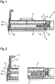
- Figure 1 shows a nozzle 1 of a floor cleaning device 2 according to the invention, which is designed as a vacuum cleaner robot.
- the nozzle 1 can be a detachable and connectable element from the floor cleaning device 2 or an inseparable part of the Floor cleaning device 2.
- the nozzle 1 comprises a housing 3 with an insertion opening 4, which in the operating state of the nozzle 1 faces a surface to be cleaned, such as a floor.
- the insertion opening 4 is also the suction opening.
- the housing 3 has an elongated, rectangular or round shape and serves to receive a floor cleaning roller 5, for example in the form of a brush roller.
- the floor cleaning roller 5 has a cylindrical shape with a peripheral surface on which, for example, brushes are arranged.
- the peripheral surface is delimited by two end surfaces, end regions or ends.
- a first end 5a is arranged on the left in the image, while the second end 5b is arranged on the right in the image.
- the floor cleaning roller 5 has an axis of rotation R. The terms used here relate axially and radially to the axis of rotation R.
- the latter comprises two bearing elements 6a, 6b which are fixed to the housing, a first bearing element 6a being fixed to the housing in the region of the first end 5a of the floor cleaning roller 5 and the second bearing element 6b being fixed to the housing in the region of the second end 6a of the floor cleaning roller 5 is provided.
- the first housing-fixed bearing element 6a is designed here as a bearing bush.
- an insertion bevel 7 adjoins the first bearing element 6a fixed to the housing and extends at an angle to the perpendicular to the axis of rotation R.
- the second bearing element 6b fixed to the housing is designed here as a ball joint.
- the floor cleaning roller 5 comprises corresponding counter bearing elements 8a and 8b arranged on the end face.
- the first counter bearing element 8a here has the shape of a bearing journal and is in the assembled state in engagement with the first bearing element 6a fixed to the housing.
- the second counter bearing element 8b here has the shape of a spherical shell and is in the assembled state in engagement with the second bearing element 6b fixed to the housing to form the ball joint.
- the floor cleaning roller 5 is driven via the ball joint consisting of the second bearing element 6b fixed to the housing and the second counter bearing element 8b.
- a toothing 9 with an internal toothing of the floor cleaning roller 5 at its second end 5b and an external toothing of the second bearing element 6b fixed to the housing intended.
- a spring element 10 which acts in the axial direction and presses the second counter bearing element 8b against the second bearing element 6b fixed to the housing. This creates a positive connection for transmitting a torque to drive the floor cleaning roller 5.
- the two-sided bearing points are located in the stable housing and are not moved when the floor cleaning roller 5 is installed, the structure is stable and requires little maintenance.
- the ejection mechanism is protected from dust outside the nozzle 1 and thus inside the generally dust-protected housing 2. Due to the storage close to the edge, the bristles of a floor cleaning roller 5 designed as a brush can be guided close to the edge of the housing, so that the area that can be cleaned during an edge vacuuming as close as possible to a wall area.
- FIGS. 2 to 4 each show a sectional view in which the central region of the floor cleaning roller 5 is not shown for reasons of clarity.
- the two ends 5a and 5b of the floor cleaning roller 5 and the associated sections of the housing 3 are thus shown.
- the removal device is shown in a rest position.
- the removal device comprises an ejection element which can be moved radially to the floor cleaning roller 5 by pressing a button 11.
- the ejection element is held in the rest position with a return spring 12.
- the ejection element comprises an inclined surface 13 which extends at an angle to the perpendicular to the axis of rotation R, whereby an ejection plunger is formed, the thickness of which increases with increasing distance from the axis of rotation R or the floor cleaning roller 5.
- a stop 14 At the radially outer end of the inclined surface 13 there is a stop 14, the surface of which runs parallel to the axis of rotation R.
- the inclined surface 13 can additionally or alternatively be formed on the circumferential end of the floor cleaning roller 5. It is advantageous to design the ejection element as a wedge with the inclined surface 13, since in this way a smaller one Height in the axial direction can be achieved.
- the floor cleaning roller 5 has a circumferential abutment counter surface 15 at the first end 5a.
- the abutment counter surface 15 can, as shown here, be designed as a collar or be provided as part of the cylindrical outer surface.
- the stop counter surface 15 extends at least substantially parallel to the axis of rotation R.
- the stop counter surface 15 is designed to bear against the stop 14.
- the end face of the mating surface 15 or that of the floor cleaning roller 5 at its first end 5a is provided with a phase 16 which is designed to bear against the inclined surface 13.
- the inclined surface 13 and the stop 14 are spaced radially from the floor cleaning roller 5.
- the first counterbearing element 8a is in engagement with the first bearing element 6a fixed to the housing and the floor cleaning roller 5 is oriented with its axis of rotation R parallel to the outer wall of the housing 3.
- FIG 3 the removal device is shown in an intermediate position.
- the ejection element is partially pushed down by pressing the button 11, that is to say in the direction of the floor cleaning roller 5, so that its inclined surface 13 is in engagement with the floor cleaning roller 5.
- the floor cleaning roller 5 is displaced axially in the direction of its second end 5b or in the direction of the second bearing element 6b fixed to the housing.
- the spring element 10 is compressed and the floor cleaning roller 5 or its first counter bearing element 8a is axially released from the first bearing element 6a fixed to the housing.
- the second counterbearing element 8b remains stationary on the second housing-fixed bearing element 6b while the other components of the floor cleaning roller 5, in particular a housing and the first counterbearing element 8a, are shifted.
- An axial stop 17 for the second end 5b of the floor cleaning roller 5 can be provided on the second bearing element 6b, which serves to limit the axial translational movement of the floor cleaning roller 5.
- the position of the axial stop 17 and / or the length of the floor cleaning roller 5 can be coordinated with one another in such a way that the stop 14 just comes to bear against the stop counter surface 15 when the second end 5 b of the floor cleaning roller 5 is in contact with the axial stop 17.
- the first counter bearing element 8a of the floor cleaning roller 5 is axially released from the first bearing element 6a fixed to the housing.
- the floor cleaning roller 5 is still oriented with its axis of rotation R parallel to the outer wall of the housing 3, as in FIG Figure 3 is shown. Due to the force of gravity, it may be that the floor cleaning roller 5 has already moved somewhat downward and is therefore no longer oriented completely parallel to the outer wall of the housing 3.
- FIG. 4 the removal device is shown in an ejection position.
- the button 11 of the ejection element was pressed further, so that the stop 14 of the ejection element, in contact with the stop counter surface 15, pushes out the floor cleaning roller 5 at its first end 5a via the insertion slope 7.
- the ball joint initially remains engaged and rotates to support the movement.
- the connection between the second bearing element 8b and the bearing element 6b fixed to the housing is released. This is supported by the spring element 10.
- the floor cleaning roller 5 is completely ejected from the insertion opening 4 of the housing 3.
- the floor cleaning roller 5 can be cleaned or replaced, for example.
- the cleaned or replaced floor cleaning roller 5 can be inserted in such a way that the floor cleaning device is placed obliquely on the floor cleaning roller 5 lying on the floor.
- the floor cleaning device with the second housing-fixed bearing element 6b is inserted onto the floor cleaning roller 5.
- the floor cleaning roller 5 is introduced via the insertion slope 7 and brought into position. This can be done using insertion aids such as ribs or similar things are supported.
- the first counter bearing element 8a finally snaps into the first housing-fixed bearing element 6a.
- the change or insertion of the floor cleaning roller 5 is now complete and the floor cleaning device can be used.
- a particularly simple, quick and hygienic removal of a floor cleaning roller can be made possible with the invention.
Claims (10)
- Appareil de nettoyage du sol (2) avec une buse (1) comprenant un corps (3) avec un orifice d'insertion (4), par lequel on peut enlever du corps (3) un cylindre de nettoyage du sol (5) puis l'y réinsérer, deux éléments de palier (6a, 6b) fixés au corps pour le support du cylindre de nettoyage du sol (5), deux éléments de contre-palier (8a, 8b) disposés sur les côtés avant opposés du cylindre de nettoyage du sol (5) et correspondant aux éléments de palier (6a, 6b) et un élément d'éjection actionnable par rapport au cylindre de nettoyage du sol (5), en position de repos de l'élément d'éjection, le cylindre de nettoyage du sol (5) étant maintenu avec ses éléments de contre-palier (8a, 8b) dans les éléments de palier (6a, 6b), caractérisé en ce que
la buse (1) comporte en outre un entraînement (13, 15) pour transformer un mouvement essentiellement uniquement radial de l'élément d'éjection en un décalage du cylindre de nettoyage du sol (5) essentiellement uniquement axial et l'élément d'éjection peut être déplacé de la position de repos dans une position intermédiaire, en position intermédiaire de l'élément d'éjection, le cylindre de nettoyage du sol (5) étant décalé axialement au moyen de l'entraînement (13, 15), ce qui fait que le cylindre de nettoyage du sol (5) est libéré axialement d'un des éléments de palier (6a) fixés au corps. - Appareil de nettoyage du sol (2) selon la revendication 1, caractérisé en ce que l'élément d'éjection comprend une butée (14) et le cylindre de nettoyage du sol (5), une contre-surface de butée (15) et l'élément d'éjection peut être déplacé de la position intermédiaire dans une position d'éjection, dans la position d'éjection de l'élément d'éjection, la butée (14) étant en liaison avec la contre-surface de butée (15), de sorte qu'un élément de contre-palier (8a) du cylindre de nettoyage du sol (5) peut être éjecté de l'élément de palier (6a) fixé au corps.
- Appareil de nettoyage du sol (2) selon la revendication 1 ou 2, caractérisé en ce que le cylindre de nettoyage du sol (5) comprend un élément à ressort (10) pour une précontrainte contre l'élément de palier (6a) fixé au corps sur la première extrémité (5a).
- Appareil de nettoyage du sol (2) selon l'une des revendications précédentes, caractérisé en ce que l'orifice d'insertion (4) est orienté vers une surface du sol à nettoyer.
- Appareil de nettoyage du sol (2) selon l'une des revendications précédentes, caractérisé en ce que le corps (3) comprend une oblique d'insertion (7) pour le premier élément de contre-palier (8a) sur la première extrémité (5a).
- Appareil de nettoyage du sol (2) selon l'une des revendications précédentes, caractérisé en ce qu'une denture intérieure du cylindre de nettoyage du sol (5) sur la deuxième extrémité (5b) de celui-ci, et une denture extérieure du deuxième élément de palier (6b) fixé au corps sont réalisées en forme de bille et en se correspondant l'une à l'autre dans la zone de la deuxième extrémité (5b).
- Appareil de nettoyage du sol (2) selon l'une des revendications précédentes, caractérisé en ce que l'élément d'éjection est disposé sur un côté supérieur opposé à la surface du sol à nettoyer ou sur une surface latérale.
- Appareil de nettoyage du sol (2) selon l'une des revendications précédentes, caractérisé en ce que l'élément d'éjection est réalisé en forme de touche à enfoncer ou de levier.
- Appareil de nettoyage du sol (2) selon l'une des revendications précédentes, caractérisé en ce que l'appareil de nettoyage du sol (2) est réalisé en forme de robot nettoyant.
- Procédé d'enlèvement d'un cylindre de nettoyage du sol (5) hors d'un appareil de nettoyage du sol (2) comprenant un corps (3) avec un orifice d'insertion (4), par lequel on peut enlever du corps (3) un cylindre de nettoyage du sol (5) puis l'y réinsérer, dans lequel un élément d'éjection est actionné essentiellement uniquement en direction radiale du cylindre de nettoyage du sol (5), et l'élément d'éjection s'engage sur le cylindre de nettoyage du sol (5) essentiellement uniquement en décalant le cylindre de nettoyage du sol (5) dans sa direction axiale, pour le libérer axialement d'un élément de palier (6a) fixé au corps.
Applications Claiming Priority (1)
| Application Number | Priority Date | Filing Date | Title |
|---|---|---|---|
| DE102017208959.8A DE102017208959A1 (de) | 2017-05-29 | 2017-05-29 | Düse für ein Bodenreinigungsgerät |
Publications (2)
| Publication Number | Publication Date |
|---|---|
| EP3424389A1 EP3424389A1 (fr) | 2019-01-09 |
| EP3424389B1 true EP3424389B1 (fr) | 2020-07-08 |
Family
ID=62110979
Family Applications (1)
| Application Number | Title | Priority Date | Filing Date |
|---|---|---|---|
| EP18170542.7A Active EP3424389B1 (fr) | 2017-05-29 | 2018-05-03 | Buse pour un appareil de nettoyage du sol |
Country Status (2)
| Country | Link |
|---|---|
| EP (1) | EP3424389B1 (fr) |
| DE (1) | DE102017208959A1 (fr) |
Families Citing this family (3)
| Publication number | Priority date | Publication date | Assignee | Title |
|---|---|---|---|---|
| FR3104018B1 (fr) * | 2019-12-09 | 2021-12-31 | Seb Sa | Tête de nettoyage équipée d’un élément de nettoyage amovible |
| CN113133714B (zh) * | 2020-01-19 | 2022-08-02 | 伊莱克斯电器股份公司 | 真空吸尘器吸嘴和真空吸尘器 |
| BE1030091B1 (de) * | 2021-12-23 | 2023-07-26 | Miele & Cie | Saugroboter |
Family Cites Families (7)
| Publication number | Priority date | Publication date | Assignee | Title |
|---|---|---|---|---|
| DE4139693A1 (de) | 1991-12-02 | 1993-06-03 | Siemens Ag | Staubsaugermundstueck |
| DE19820628C1 (de) | 1998-05-08 | 1999-09-23 | Kaercher Gmbh & Co Alfred | Kehrmaschine |
| IT1310795B1 (it) | 1999-12-10 | 2002-02-22 | Vidoni Mario | Apparecchio di pulizia con spazzola intercambiabile |
| WO2006061045A1 (fr) | 2004-12-11 | 2006-06-15 | Alfred Kärcher Gmbh & Co. Kg | Appareil de nettoyage de sol |
| EP1827192B1 (fr) * | 2004-12-11 | 2011-08-10 | Alfred Kärcher GmbH & Co. KG | Appareil de nettoyage de sol |
| US8037571B2 (en) * | 2009-09-01 | 2011-10-18 | Techtronic Floor Care Technology Limited | Vacuum cleaner accessory tool having a removable brush |
| JP5852890B2 (ja) | 2012-01-17 | 2016-02-03 | シャープ株式会社 | 回転ブラシの取付構造およびそれを備えた掃除機 |
-
2017
- 2017-05-29 DE DE102017208959.8A patent/DE102017208959A1/de not_active Withdrawn
-
2018
- 2018-05-03 EP EP18170542.7A patent/EP3424389B1/fr active Active
Non-Patent Citations (1)
| Title |
|---|
| None * |
Also Published As
| Publication number | Publication date |
|---|---|
| DE102017208959A1 (de) | 2018-11-29 |
| EP3424389A1 (fr) | 2019-01-09 |
Similar Documents
| Publication | Publication Date | Title |
|---|---|---|
| EP3424389B1 (fr) | Buse pour un appareil de nettoyage du sol | |
| EP3474717B1 (fr) | Appareil de nettoyage par voie humide avec un cylindre de nettoyage rotatif | |
| DE102014110025A1 (de) | Saugroboter mit rotierender Borstwalze und Reinigungsverfahren für eine Borstwalze eines Saugroboters | |
| EP3117754B1 (fr) | Appareil de nettoyage comprenant un rouleau de nettoyage en rotation | |
| EP2866631A1 (fr) | Combinaison d'un mini-aspirateur et d'un boîtier d'aspirateur ainsi que mini-aspirateur et boîtier d'aspirateur | |
| WO2018001716A1 (fr) | Appareil de nettoyage humide comprenant un rouleau de nettoyage | |
| DE102014113517B4 (de) | Selbstreinigendes Bürstensystem zum Reinigen von Oberflächen | |
| DE102009034955B4 (de) | Selbsttätig verfahrbares Bodenstaub-Aufsammelgerät | |
| DE102018219575A1 (de) | Reinigungsroboter | |
| EP3581082B1 (fr) | Robot d'aspiration et procédé de commande d'un robot d'aspiration | |
| EP2891444A1 (fr) | Robot aspirateur avec brosses latérales | |
| DE102014108217A1 (de) | Reinigungssystem | |
| EP3500147B1 (fr) | Appareil de nettoyage humide avec rouleau de nettoyage | |
| DE102021116685B3 (de) | Bodenreinigungsmaschine | |
| EP3085291B1 (fr) | Aspirateur et unite de filtre destinee a etre utilisee dans l'aspirateur | |
| WO2021254823A1 (fr) | Dispositif de collecte de poussière destiné à une machine-outil | |
| WO2022063605A1 (fr) | Dispositif de filtration et procédé de nettoyage y relatif | |
| DE102020116426A1 (de) | Saugreinigungsgerät | |
| DE102010037869A1 (de) | Saug- und/oder Kehrgerät | |
| EP3185742A1 (fr) | Buse d'aspiration et appareil d'aspiration de surfaces dures | |
| EP3981312B1 (fr) | Dispositif de nettoyage | |
| EP4111931B1 (fr) | Machine de nettoyage du sol | |
| DE102017208967B4 (de) | Saugreinigungsroboter | |
| DE102021116686B3 (de) | Bodenreinigungsmaschine | |
| EP1520334B1 (fr) | Moteur electrique comprenant un porte-balai a au moins deux balais de charbon |
Legal Events
| Date | Code | Title | Description |
|---|---|---|---|
| PUAI | Public reference made under article 153(3) epc to a published international application that has entered the european phase |
Free format text: ORIGINAL CODE: 0009012 |
|
| STAA | Information on the status of an ep patent application or granted ep patent |
Free format text: STATUS: THE APPLICATION HAS BEEN PUBLISHED |
|
| AK | Designated contracting states |
Kind code of ref document: A1 Designated state(s): AL AT BE BG CH CY CZ DE DK EE ES FI FR GB GR HR HU IE IS IT LI LT LU LV MC MK MT NL NO PL PT RO RS SE SI SK SM TR |
|
| AX | Request for extension of the european patent |
Extension state: BA ME |
|
| STAA | Information on the status of an ep patent application or granted ep patent |
Free format text: STATUS: REQUEST FOR EXAMINATION WAS MADE |
|
| 17P | Request for examination filed |
Effective date: 20190709 |
|
| RBV | Designated contracting states (corrected) |
Designated state(s): AL AT BE BG CH CY CZ DE DK EE ES FI FR GB GR HR HU IE IS IT LI LT LU LV MC MK MT NL NO PL PT RO RS SE SI SK SM TR |
|
| GRAP | Despatch of communication of intention to grant a patent |
Free format text: ORIGINAL CODE: EPIDOSNIGR1 |
|
| STAA | Information on the status of an ep patent application or granted ep patent |
Free format text: STATUS: GRANT OF PATENT IS INTENDED |
|
| INTG | Intention to grant announced |
Effective date: 20200203 |
|
| GRAS | Grant fee paid |
Free format text: ORIGINAL CODE: EPIDOSNIGR3 |
|
| GRAA | (expected) grant |
Free format text: ORIGINAL CODE: 0009210 |
|
| STAA | Information on the status of an ep patent application or granted ep patent |
Free format text: STATUS: THE PATENT HAS BEEN GRANTED |
|
| AK | Designated contracting states |
Kind code of ref document: B1 Designated state(s): AL AT BE BG CH CY CZ DE DK EE ES FI FR GB GR HR HU IE IS IT LI LT LU LV MC MK MT NL NO PL PT RO RS SE SI SK SM TR |
|
| REG | Reference to a national code |
Ref country code: CH Ref legal event code: EP Ref country code: AT Ref legal event code: REF Ref document number: 1287544 Country of ref document: AT Kind code of ref document: T Effective date: 20200715 |
|
| REG | Reference to a national code |
Ref country code: DE Ref legal event code: R096 Ref document number: 502018001824 Country of ref document: DE |
|
| REG | Reference to a national code |
Ref country code: IE Ref legal event code: FG4D Free format text: LANGUAGE OF EP DOCUMENT: GERMAN |
|
| REG | Reference to a national code |
Ref country code: LT Ref legal event code: MG4D |
|
| REG | Reference to a national code |
Ref country code: NL Ref legal event code: MP Effective date: 20200708 |
|
| PG25 | Lapsed in a contracting state [announced via postgrant information from national office to epo] |
Ref country code: FI Free format text: LAPSE BECAUSE OF FAILURE TO SUBMIT A TRANSLATION OF THE DESCRIPTION OR TO PAY THE FEE WITHIN THE PRESCRIBED TIME-LIMIT Effective date: 20200708 Ref country code: LT Free format text: LAPSE BECAUSE OF FAILURE TO SUBMIT A TRANSLATION OF THE DESCRIPTION OR TO PAY THE FEE WITHIN THE PRESCRIBED TIME-LIMIT Effective date: 20200708 Ref country code: ES Free format text: LAPSE BECAUSE OF FAILURE TO SUBMIT A TRANSLATION OF THE DESCRIPTION OR TO PAY THE FEE WITHIN THE PRESCRIBED TIME-LIMIT Effective date: 20200708 Ref country code: HR Free format text: LAPSE BECAUSE OF FAILURE TO SUBMIT A TRANSLATION OF THE DESCRIPTION OR TO PAY THE FEE WITHIN THE PRESCRIBED TIME-LIMIT Effective date: 20200708 Ref country code: BG Free format text: LAPSE BECAUSE OF FAILURE TO SUBMIT A TRANSLATION OF THE DESCRIPTION OR TO PAY THE FEE WITHIN THE PRESCRIBED TIME-LIMIT Effective date: 20201008 Ref country code: SE Free format text: LAPSE BECAUSE OF FAILURE TO SUBMIT A TRANSLATION OF THE DESCRIPTION OR TO PAY THE FEE WITHIN THE PRESCRIBED TIME-LIMIT Effective date: 20200708 Ref country code: PT Free format text: LAPSE BECAUSE OF FAILURE TO SUBMIT A TRANSLATION OF THE DESCRIPTION OR TO PAY THE FEE WITHIN THE PRESCRIBED TIME-LIMIT Effective date: 20201109 Ref country code: GR Free format text: LAPSE BECAUSE OF FAILURE TO SUBMIT A TRANSLATION OF THE DESCRIPTION OR TO PAY THE FEE WITHIN THE PRESCRIBED TIME-LIMIT Effective date: 20201009 Ref country code: NO Free format text: LAPSE BECAUSE OF FAILURE TO SUBMIT A TRANSLATION OF THE DESCRIPTION OR TO PAY THE FEE WITHIN THE PRESCRIBED TIME-LIMIT Effective date: 20201008 |
|
| PG25 | Lapsed in a contracting state [announced via postgrant information from national office to epo] |
Ref country code: RS Free format text: LAPSE BECAUSE OF FAILURE TO SUBMIT A TRANSLATION OF THE DESCRIPTION OR TO PAY THE FEE WITHIN THE PRESCRIBED TIME-LIMIT Effective date: 20200708 Ref country code: LV Free format text: LAPSE BECAUSE OF FAILURE TO SUBMIT A TRANSLATION OF THE DESCRIPTION OR TO PAY THE FEE WITHIN THE PRESCRIBED TIME-LIMIT Effective date: 20200708 Ref country code: PL Free format text: LAPSE BECAUSE OF FAILURE TO SUBMIT A TRANSLATION OF THE DESCRIPTION OR TO PAY THE FEE WITHIN THE PRESCRIBED TIME-LIMIT Effective date: 20200708 Ref country code: IS Free format text: LAPSE BECAUSE OF FAILURE TO SUBMIT A TRANSLATION OF THE DESCRIPTION OR TO PAY THE FEE WITHIN THE PRESCRIBED TIME-LIMIT Effective date: 20201108 |
|
| PG25 | Lapsed in a contracting state [announced via postgrant information from national office to epo] |
Ref country code: NL Free format text: LAPSE BECAUSE OF FAILURE TO SUBMIT A TRANSLATION OF THE DESCRIPTION OR TO PAY THE FEE WITHIN THE PRESCRIBED TIME-LIMIT Effective date: 20200708 |
|
| REG | Reference to a national code |
Ref country code: DE Ref legal event code: R097 Ref document number: 502018001824 Country of ref document: DE |
|
| PG25 | Lapsed in a contracting state [announced via postgrant information from national office to epo] |
Ref country code: IT Free format text: LAPSE BECAUSE OF FAILURE TO SUBMIT A TRANSLATION OF THE DESCRIPTION OR TO PAY THE FEE WITHIN THE PRESCRIBED TIME-LIMIT Effective date: 20200708 Ref country code: SM Free format text: LAPSE BECAUSE OF FAILURE TO SUBMIT A TRANSLATION OF THE DESCRIPTION OR TO PAY THE FEE WITHIN THE PRESCRIBED TIME-LIMIT Effective date: 20200708 Ref country code: EE Free format text: LAPSE BECAUSE OF FAILURE TO SUBMIT A TRANSLATION OF THE DESCRIPTION OR TO PAY THE FEE WITHIN THE PRESCRIBED TIME-LIMIT Effective date: 20200708 Ref country code: RO Free format text: LAPSE BECAUSE OF FAILURE TO SUBMIT A TRANSLATION OF THE DESCRIPTION OR TO PAY THE FEE WITHIN THE PRESCRIBED TIME-LIMIT Effective date: 20200708 Ref country code: DK Free format text: LAPSE BECAUSE OF FAILURE TO SUBMIT A TRANSLATION OF THE DESCRIPTION OR TO PAY THE FEE WITHIN THE PRESCRIBED TIME-LIMIT Effective date: 20200708 Ref country code: CZ Free format text: LAPSE BECAUSE OF FAILURE TO SUBMIT A TRANSLATION OF THE DESCRIPTION OR TO PAY THE FEE WITHIN THE PRESCRIBED TIME-LIMIT Effective date: 20200708 |
|
| PLBE | No opposition filed within time limit |
Free format text: ORIGINAL CODE: 0009261 |
|
| STAA | Information on the status of an ep patent application or granted ep patent |
Free format text: STATUS: NO OPPOSITION FILED WITHIN TIME LIMIT |
|
| PG25 | Lapsed in a contracting state [announced via postgrant information from national office to epo] |
Ref country code: AL Free format text: LAPSE BECAUSE OF FAILURE TO SUBMIT A TRANSLATION OF THE DESCRIPTION OR TO PAY THE FEE WITHIN THE PRESCRIBED TIME-LIMIT Effective date: 20200708 |
|
| 26N | No opposition filed |
Effective date: 20210409 |
|
| PG25 | Lapsed in a contracting state [announced via postgrant information from national office to epo] |
Ref country code: SK Free format text: LAPSE BECAUSE OF FAILURE TO SUBMIT A TRANSLATION OF THE DESCRIPTION OR TO PAY THE FEE WITHIN THE PRESCRIBED TIME-LIMIT Effective date: 20200708 |
|
| PG25 | Lapsed in a contracting state [announced via postgrant information from national office to epo] |
Ref country code: SI Free format text: LAPSE BECAUSE OF FAILURE TO SUBMIT A TRANSLATION OF THE DESCRIPTION OR TO PAY THE FEE WITHIN THE PRESCRIBED TIME-LIMIT Effective date: 20200708 |
|
| REG | Reference to a national code |
Ref country code: CH Ref legal event code: PL |
|
| PG25 | Lapsed in a contracting state [announced via postgrant information from national office to epo] |
Ref country code: LU Free format text: LAPSE BECAUSE OF NON-PAYMENT OF DUE FEES Effective date: 20210503 Ref country code: MC Free format text: LAPSE BECAUSE OF FAILURE TO SUBMIT A TRANSLATION OF THE DESCRIPTION OR TO PAY THE FEE WITHIN THE PRESCRIBED TIME-LIMIT Effective date: 20200708 Ref country code: LI Free format text: LAPSE BECAUSE OF NON-PAYMENT OF DUE FEES Effective date: 20210531 Ref country code: CH Free format text: LAPSE BECAUSE OF NON-PAYMENT OF DUE FEES Effective date: 20210531 |
|
| REG | Reference to a national code |
Ref country code: BE Ref legal event code: MM Effective date: 20210531 |
|
| PG25 | Lapsed in a contracting state [announced via postgrant information from national office to epo] |
Ref country code: IE Free format text: LAPSE BECAUSE OF NON-PAYMENT OF DUE FEES Effective date: 20210503 |
|
| PG25 | Lapsed in a contracting state [announced via postgrant information from national office to epo] |
Ref country code: BE Free format text: LAPSE BECAUSE OF NON-PAYMENT OF DUE FEES Effective date: 20210531 |
|
| PG25 | Lapsed in a contracting state [announced via postgrant information from national office to epo] |
Ref country code: CY Free format text: LAPSE BECAUSE OF FAILURE TO SUBMIT A TRANSLATION OF THE DESCRIPTION OR TO PAY THE FEE WITHIN THE PRESCRIBED TIME-LIMIT Effective date: 20200708 |
|
| PG25 | Lapsed in a contracting state [announced via postgrant information from national office to epo] |
Ref country code: HU Free format text: LAPSE BECAUSE OF FAILURE TO SUBMIT A TRANSLATION OF THE DESCRIPTION OR TO PAY THE FEE WITHIN THE PRESCRIBED TIME-LIMIT; INVALID AB INITIO Effective date: 20180503 |
|
| PGFP | Annual fee paid to national office [announced via postgrant information from national office to epo] |
Ref country code: FR Payment date: 20230517 Year of fee payment: 6 Ref country code: DE Payment date: 20230531 Year of fee payment: 6 |
|
| PGFP | Annual fee paid to national office [announced via postgrant information from national office to epo] |
Ref country code: GB Payment date: 20230522 Year of fee payment: 6 |
|
| PG25 | Lapsed in a contracting state [announced via postgrant information from national office to epo] |
Ref country code: MK Free format text: LAPSE BECAUSE OF FAILURE TO SUBMIT A TRANSLATION OF THE DESCRIPTION OR TO PAY THE FEE WITHIN THE PRESCRIBED TIME-LIMIT Effective date: 20200708 |