EP3423652B1 - Latch arrangement having a handle - Google Patents
Latch arrangement having a handle Download PDFInfo
- Publication number
- EP3423652B1 EP3423652B1 EP17759386.0A EP17759386A EP3423652B1 EP 3423652 B1 EP3423652 B1 EP 3423652B1 EP 17759386 A EP17759386 A EP 17759386A EP 3423652 B1 EP3423652 B1 EP 3423652B1
- Authority
- EP
- European Patent Office
- Prior art keywords
- panel
- locking element
- latch
- latch arrangement
- frame
- Prior art date
- Legal status (The legal status is an assumption and is not a legal conclusion. Google has not performed a legal analysis and makes no representation as to the accuracy of the status listed.)
- Active
Links
- 230000007246 mechanism Effects 0.000 claims description 39
- 238000006073 displacement reaction Methods 0.000 claims description 19
- ORQBXQOJMQIAOY-UHFFFAOYSA-N nobelium Chemical compound [No] ORQBXQOJMQIAOY-UHFFFAOYSA-N 0.000 description 5
- 238000000034 method Methods 0.000 description 2
- 230000003993 interaction Effects 0.000 description 1
- 238000004519 manufacturing process Methods 0.000 description 1
- 238000012986 modification Methods 0.000 description 1
- 230000004048 modification Effects 0.000 description 1
Images


Classifications
-
- E—FIXED CONSTRUCTIONS
- E05—LOCKS; KEYS; WINDOW OR DOOR FITTINGS; SAFES
- E05C—BOLTS OR FASTENING DEVICES FOR WINGS, SPECIALLY FOR DOORS OR WINDOWS
- E05C1/00—Fastening devices with bolts moving rectilinearly
- E05C1/08—Fastening devices with bolts moving rectilinearly with latching action
- E05C1/12—Fastening devices with bolts moving rectilinearly with latching action with operating handle or equivalent member moving otherwise than rigidly with the latch
-
- E—FIXED CONSTRUCTIONS
- E05—LOCKS; KEYS; WINDOW OR DOOR FITTINGS; SAFES
- E05B—LOCKS; ACCESSORIES THEREFOR; HANDCUFFS
- E05B15/00—Other details of locks; Parts for engagement by bolts of fastening devices
-
- E—FIXED CONSTRUCTIONS
- E05—LOCKS; KEYS; WINDOW OR DOOR FITTINGS; SAFES
- E05B—LOCKS; ACCESSORIES THEREFOR; HANDCUFFS
- E05B17/00—Accessories in connection with locks
- E05B17/20—Means independent of the locking mechanism for preventing unauthorised opening, e.g. for securing the bolt in the fastening position
- E05B17/2007—Securing, deadlocking or "dogging" the bolt in the fastening position
- E05B17/2049—Securing, deadlocking or "dogging" the bolt in the fastening position following the movement of the bolt
- E05B17/2053—Securing, deadlocking or "dogging" the bolt in the fastening position following the movement of the bolt moving pivotally or rotatively relating to the bolt
-
- E—FIXED CONSTRUCTIONS
- E05—LOCKS; KEYS; WINDOW OR DOOR FITTINGS; SAFES
- E05B—LOCKS; ACCESSORIES THEREFOR; HANDCUFFS
- E05B17/00—Accessories in connection with locks
- E05B17/20—Means independent of the locking mechanism for preventing unauthorised opening, e.g. for securing the bolt in the fastening position
- E05B17/2007—Securing, deadlocking or "dogging" the bolt in the fastening position
- E05B17/2049—Securing, deadlocking or "dogging" the bolt in the fastening position following the movement of the bolt
- E05B17/2057—Securing, deadlocking or "dogging" the bolt in the fastening position following the movement of the bolt moving rectilinearly relating to the bolt
-
- E—FIXED CONSTRUCTIONS
- E05—LOCKS; KEYS; WINDOW OR DOOR FITTINGS; SAFES
- E05B—LOCKS; ACCESSORIES THEREFOR; HANDCUFFS
- E05B63/00—Locks or fastenings with special structural characteristics
- E05B63/0052—Locks mounted on the "frame" cooperating with means on the "wing"
-
- E—FIXED CONSTRUCTIONS
- E05—LOCKS; KEYS; WINDOW OR DOOR FITTINGS; SAFES
- E05B—LOCKS; ACCESSORIES THEREFOR; HANDCUFFS
- E05B63/00—Locks or fastenings with special structural characteristics
- E05B63/24—Arrangements in which the fastening members which engage one another are mounted respectively on the wing and the frame and are both movable, e.g. for release by moving either of them
- E05B63/244—Arrangements in which the fastening members which engage one another are mounted respectively on the wing and the frame and are both movable, e.g. for release by moving either of them the striker being movable for latching, the bolt for unlatching, or vice versa
-
- E—FIXED CONSTRUCTIONS
- E05—LOCKS; KEYS; WINDOW OR DOOR FITTINGS; SAFES
- E05B—LOCKS; ACCESSORIES THEREFOR; HANDCUFFS
- E05B63/00—Locks or fastenings with special structural characteristics
- E05B63/24—Arrangements in which the fastening members which engage one another are mounted respectively on the wing and the frame and are both movable, e.g. for release by moving either of them
- E05B63/248—Arrangements in which the fastening members which engage one another are mounted respectively on the wing and the frame and are both movable, e.g. for release by moving either of them the striker being movable for latching, and pushed back by a member on the wing for unlatching, or vice versa
-
- E—FIXED CONSTRUCTIONS
- E05—LOCKS; KEYS; WINDOW OR DOOR FITTINGS; SAFES
- E05B—LOCKS; ACCESSORIES THEREFOR; HANDCUFFS
- E05B65/00—Locks or fastenings for special use
- E05B65/06—Locks or fastenings for special use for swing doors or windows, i.e. opening inwards and outwards
-
- E—FIXED CONSTRUCTIONS
- E05—LOCKS; KEYS; WINDOW OR DOOR FITTINGS; SAFES
- E05B—LOCKS; ACCESSORIES THEREFOR; HANDCUFFS
- E05B65/00—Locks or fastenings for special use
- E05B65/08—Locks or fastenings for special use for sliding wings
-
- E—FIXED CONSTRUCTIONS
- E05—LOCKS; KEYS; WINDOW OR DOOR FITTINGS; SAFES
- E05B—LOCKS; ACCESSORIES THEREFOR; HANDCUFFS
- E05B65/00—Locks or fastenings for special use
- E05B65/08—Locks or fastenings for special use for sliding wings
- E05B65/0835—Locks or fastenings for special use for sliding wings the bolts pivoting about an axis parallel to the wings
-
- E—FIXED CONSTRUCTIONS
- E05—LOCKS; KEYS; WINDOW OR DOOR FITTINGS; SAFES
- E05B—LOCKS; ACCESSORIES THEREFOR; HANDCUFFS
- E05B65/00—Locks or fastenings for special use
- E05B65/10—Locks or fastenings for special use for panic or emergency doors
- E05B65/1046—Panic bars
-
- E—FIXED CONSTRUCTIONS
- E05—LOCKS; KEYS; WINDOW OR DOOR FITTINGS; SAFES
- E05B—LOCKS; ACCESSORIES THEREFOR; HANDCUFFS
- E05B65/00—Locks or fastenings for special use
- E05B65/10—Locks or fastenings for special use for panic or emergency doors
- E05B65/1046—Panic bars
- E05B65/106—Panic bars pivoting
- E05B65/1066—Panic bars pivoting the pivot axis being substantially parallel to the longitudinal axis of the bar
-
- E—FIXED CONSTRUCTIONS
- E05—LOCKS; KEYS; WINDOW OR DOOR FITTINGS; SAFES
- E05C—BOLTS OR FASTENING DEVICES FOR WINGS, SPECIALLY FOR DOORS OR WINDOWS
- E05C3/00—Fastening devices with bolts moving pivotally or rotatively
- E05C3/12—Fastening devices with bolts moving pivotally or rotatively with latching action
- E05C3/16—Fastening devices with bolts moving pivotally or rotatively with latching action with operating handle or equivalent member moving otherwise than rigidly with the latch
-
- E—FIXED CONSTRUCTIONS
- E05—LOCKS; KEYS; WINDOW OR DOOR FITTINGS; SAFES
- E05B—LOCKS; ACCESSORIES THEREFOR; HANDCUFFS
- E05B65/00—Locks or fastenings for special use
- E05B65/006—Locks or fastenings for special use for covers or panels
-
- E—FIXED CONSTRUCTIONS
- E05—LOCKS; KEYS; WINDOW OR DOOR FITTINGS; SAFES
- E05C—BOLTS OR FASTENING DEVICES FOR WINGS, SPECIALLY FOR DOORS OR WINDOWS
- E05C19/00—Other devices specially designed for securing wings, e.g. with suction cups
- E05C19/001—Other devices specially designed for securing wings, e.g. with suction cups with bolts extending over a considerable extent, e.g. nearly along the whole length of at least one side of the wing
- E05C19/002—Rotating about a longitudinal axis
Definitions
- the presently disclosed subject matter relates to a latch arrangement having a handle, in general and in particular for a latch arrangement for fastening a panel of a door or a window to a frame element.
- a latch arrangement for fastening a panel of a door or a window to a frame element is an arrangement which includes a locking element displaceable with respect to the panel between a locked position in which the locking element is engaged with the frame element and the panel precluding thereby the displacement of the panel away from the frame element.
- the locking element can be mounted on the frame element and displaceable towards and away from the panel so as to lock the panel to the frame element.
- Such a latch arrangement is disclosed e.g. in EP 0 270 437 A1 and in US 3,973,794 .
- the locking element can be mounted on the panel and can be displaceable towards and away from the frame element so as to lock the panel to the frame element.
- US 4803808 discloses a swivel fitting for an outwardly opening window, with a device for moving the casement frame between the closed position and the open position, for example in the form of a hand crank, with position-fixing arm driven by the crank and with an operating handle on one frame member of the stationary frame, in order to fix the casement frame in the closed position.
- At least one locking plate is included on the casement frame which co-operates with a locking element on a drive rod operable by the handle. When the window is in the closed position, a locking projection of the locking plate protrudes into a groove in the stationary frame so that the closing movement of the window may be supported relatively early by actuation of the handle and to ensure high security against break-in.
- latch arrangement for fastening a panel of a door or a window to a frame element according to the features set out in claim 1.
- the actuating mechanism can include a manually operable handle, the actuating mechanism being mounted on the panel and being configured to selectively engage the locking element and to displace the locking element away from the depression to the unlocked position.
- the handle can be pivotally mounted on the panel and can be displaceable between a first positon in which the locking element can be urged away from the depression and a second position in which the locking element can be free to engage the depression. In the first position the handle can be pivoted towards an opening direction of the panel.
- the actuating mechanism includes an actuating member mounted on the panel and configured to selectively move towards the locking element whereby the locking element can be displaced to the unlocked position.
- the handle incudes a portion engaging the actuating member, and wherein the handle can be configured such that when the handle can be pivoted the actuating member can be pushed towards the locking element whereby the locking element can be displaced to the unlocked position.
- the handle incudes a panic bar configured to pivot towards the panel and a sloped member configured to pivot with the panic bar, the sloped member being configured to engages the actuating member, and wherein when the panic bar can be pivoted towards the panel the sloped member can be configured urge the actuating member to slide towards the locking element.
- the actuating member can be configured to slide in a groove extending transversely to the panel.
- the latch arrangement further includes a stop latch displaceably attached to the locking element and being configured to selectively displace between a secured position in which the locking element can be secured in the locked position, and a released position in which the locking element can be free to displace to the unlocked position, wherein the actuating mechanism can be configured to selectively displace the stop latch to the released position.
- the actuating mechanism can be configured such that motion of the handle performs sequentially release of the stop latch following by a displacement of the locking element out of engagement.
- the stop latch can be mounted on said locking element and can be configured to selectively engage an abutment feature such that displacement of said locking element to the unlocked position is precluded.
- the stop latch can be slidably mounted on said locking element and is configured to slide between a secured position in which at least one portion thereof is engaged with said abutment feature and a released position in which said at least one portion is retracted away from said abutment feature such that the locking element is free to be displaced to the unlocked position.
- the abutment feature can be defined on the panel.
- the stop latch can be pivotally mounted on the locking element and can be configured to pivot between a secured position in which the locking element can be secured in the locked position and a released position in which said locking element can be free to be displaced to said unlocked position, and wherein said actuating mechanism can be configured to selectively pivot said stop latch to said released position.
- the abutment feature can be defined on the frame element.
- the actuating mechanism can include a catch member and wherein in the secured position the stop latch can be engaged with the catch member.
- the locking element is pivotally mounted on the frame element, and wherein the actuating mechanism can be configured to selectively pivot the locking element away from the depression to the unlocked position.
- the locking element in the locked position can be extended at an oblique angle with respect to the panel such that a first end of the locking element can be configured to engage the depression and while a second end of the locking element can be engaged with a portion of the frame element, and wherein in the locked position displacement of the panel towards an opening direction of the panel can be opposed by compressive forces exerted on the locking element and on the portion of the frame element.
- the panel can be a sliding panel configured to slide towards and away from the frame element, between a closed state and an open state.
- the panel can be a hinged panel configured to rotate towards and away from the frame element, between a closed state and an open state.
- shift and “displace” as used herein the specification and claims refers generically to any mechanical displacement of various elements including but not limited to linear displacement, pivot movement, rotational movement etc.
- panel is used to refer to the element deployed across at least part of the opening in the closed state.
- the panels and corresponding closures may be doors, windows or any other type of opening which is selectively closed (or partially closed) by a hinged or a sliding panel.
- the phrase "mounted on” as used herein refers to a first element affixed to a second element in any disposition between the two elements including the first element disposed on the second element, inside the second element, affixed to any outer surface of the second element, etc.
- the phrase "defined on” as used herein refers to a feature or an element provided on a member in any manner, including integrally formed with the member, attached to the member etc.
- door refers generically to any moving panel configured to selectively block off and allow access through an opening to a structure, such as a building or vehicle, an entrance to a confined area, or between two confined areas including hinged door, sliding door, a window of any type, as well as a hood and a trunk for covering vehicles or portions thereof, etc.
- the invention relates to a latch arrangement for fastening a panel, such as a door or a window, to a frame element around an opening.
- the latch arrangements includes a locking element, such as a bolt or latch, displaceably mounted relative to the frame element for selectively engaging a corresponding depression in the panel of the door or the window.
- the latch arrangement can be provided with a manually operable handle mounted on the door or the window panel which interacts, by means of an actuating mechanism, with the locking element on the frame element.
- the actuating mechanism is configured to selectively displace the locking element out of engagement with the depression defined on the door or the window panel.
- the handle can have various shapes and can be configured in different manners, for example direction of operation, and methods of interactions with the actuating mechanism.
- FIG. 1A-1D A first implementation which does not form part of the invention in the context of a sliding bolt will be presented herein with reference to Figs. 1A-1D , and illustrates the underlying principles of an aspect of the invention.
- Various particularly preferred implementations illustrated in the remaining drawings employ locking configurations in which a locking element is pivotally mounted relative to a frame element. Locking configurations of this type have been found to provide highly advantageous mechanical properties, particularly where any applied load applied to try to force open the panel is distributed along a locking element which extends along a significant length of the frame element (typically more than 10%, and in some cases along a majority, of the length of the frame element).
- An aspect of the present invention provides a solution for opening of such frame-mounted locking mechanisms via a manually-operated handle mounted on the panel, thereby combining the mechanical advantages of the frame-mounted locking configuration with the intuitive operation of a panel-mounted handle.
- the actuating mechanism is preferably configured such that motion of the handle performs sequentially release of the deadlock and then displacement of the locking element out of engagement.
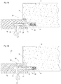
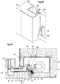
- Figs. 1A to 1D show a hinged door including a door panel 10, a frame element 12, and a latch arrangement 20 for fastening the panel 10 to the frame element 12.
- a latch arrangement 20 for fastening the panel 10 to the frame element 12.
- the door panel 10 is configured to abut, in the closed state thereof, against a shoulder portion 14 defined on an abutting portion 13 of the frame element 12.
- the abutting portion 13 is so disposed with respect to the door panel 10 such that it faces a frame facing portion 15 of the door panel 10, when the latter is in the closed state.
- the latch arrangement 20 includes a locking element, here illustrated as a retractable pin 22 slidably mounted inside a frame groove 24, which is defined on the abutting portion 13 of the frame element 12.
- the retractable pin 22 is configured such that a portion thereof slides in and out of the frame groove 24, between a locked position, as shown in Fig. 1A , and an unlocked positon, as shown in Fig. 1B and as explained hereinafter.
- the retractable pin 22 can include a sloped tip 23 which is configured to extend out of the frame groove 24 in the locked position.
- the retractable pin 22, can be biased by a spring 25 mounted inside the frame groove 24 such that the retractable pin 22 is normally urged to the locked position, i.e. at least a portion of the retractable pin 22 projects outwards from the frame groove 24.
- the door panel 10 includes a panel groove 18 defined on the frame facing portion 15 of the door panel 10.
- the panel 10 is configured such that when in the closed state thereof, the panel groove 18 is coaxially disposed with respect to the frame groove 24. This way, in the closed state of the door panel 10, the retractable pin 22 extends outwardly from the frame groove 24 and into the panel groove 18, locking thereby the panel 10 to the frame element 12, as shown in Fig. 1 A .
- the retractable pin 22 is thus displaceable between a locked position and an unlocked position.
- the retractable pin 22 In the locked position, the retractable pin 22 extends out of the frame groove 24 such that when the panel 10 is in the closed state thereof, at least a portion of the retractable pin 22, i.e., the sloped tip 23, is engaged with the panel groove 18 on the panel 10, locking thereby the panel to the frame element 12.
- the retractable pin 22 In the unlocked position, on the other hand, the retractable pin 22 is disengaged from the panel groove 18 unlocking thereby the panel 10 from the frame element 12, as shown in Fig. 1B .
- the retractable pin 22 In the unlocked position, the retractable pin 22 can be fully or partially disposed inside the frame groove 24, such that the panel 10 can be pivoted to the open state of the door or the window.
- retractable pin 22 is configured to engage in the locked position the panel groove 18, according to other examples the panel groove 18 can be replaced with a depression configured to allow firm engagement with the retractable pin 22.
- the latch arrangement 20 further includes an actuating mechanism, having an actuating member, here illustrated as an actuating pin 30 slidably disposed inside the panel groove 18.
- the actuating pin 30, according to an example, has a length slightly smaller than the length of the panel groove 18 such that actuating pin 30 can slide inside the panel groove 18 while the end of the panel groove 18 close to the frame facing portion 15 of the door panel 10 is unoccupied. This way, the actuating pin 30 can slide between a retracted position, as shown in Figs 1A and 1D , in which the actuating pin 30 is disposed on the inner end of the panel groove 18, and a forward position, as shown in Figs. 1B and 1C , in which actuating pin 30 is disposed on the outer end of the panel groove 18, such that the end of the actuating pin 30 is substantially flush with the frame facing portion 15 of the door panel 10.
- the actuating pin 30 can be slid to the retracted position, allowing the retractable pin 22 to engage the panel groove 18, and the sloped tip 23 to be inserted inside the unoccupied end of the panel groove 18, fastening thereby the door panel 10 to the frame element 12.
- the actuating pin 30 can however, be slid to the forwards position pushing thereby the retracted pin 22 out of the panel groove 18 to the unlocked position thereof, such that the sloped tip 23 is disengaged from the panel groove 18 and the door panel 10 is free to be displaced away from the frame element 12 and to the opened state of the door panel 10, as shown in Fig. 1B .
- a manually operable handle 35 is coupled to the actuating pin 30, and protrudes from the surface of the panel 10, allowing thereby a user to interact therewith.
- the handle 35 can extended through an opening 37 defined between the panel groove 18 and an outer surface of the panel 10.
- the opening 37 can be configured to allow sideward displacement of the handle 35.
- the opening 37 can be wider than the width of the handle 35 such that the latter is free to be displaced in an axis parallel to the axis of the panel groove 18. Accordingly, when the door panel 10 is in the closed state thereof the handle 35 can be moved towards the frame element 12, displacing thereby the actuating pin 30 inside the panel groove 18 to the forward position thereof.
- the frame facing portion 15 of the panel 10 can include a sloped portion 19 configured to interact with the sloped tip 23 of the retractable pin 22. That is to say, the sloping direction of the sloped portion 19 corresponds the sloping direction of the sloped tip 23, such that when the panel is pivoted from the opened state thereof to the closed states thereof the sloped portion 19 of the frame facing portion 15 engages the sloped tip 23.
- the sloped portion 19 engages the sloped tip 23 of the retractable pin 22 and gradually displaces the retractable pin 22 to the retracted position thereof, such that the frame facing portion 15 can abut the shoulder portion 14.
- retractable pin 22 can be replaced with ball bearing configured to selectively engage the panel groove 18.
- the ball bearing can be configured to be retracted when it is engaged by the frame facing portion 15, for example, when the panel 10 is displaced to the closed state thereof This way, the frame facing portion 15 can be formed without the sloped portion 19.
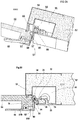
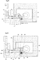
- Fig. 2A to 2E illustrates an example according to the invention of a door or a window having latch arrangement 51 configured for fastening a panel 50 to a frame element 52.
- the panel 50 is a panel of a hinged door and is configured to abut, in the closed state thereof, against a shoulder portion 54 defined on the frame element 52.
- the frame element 52 further defines a housing 55 for holding therein the latch arrangement 51, such that the frame facing portion 57 of the door panel 50 can be engaged by the latch arrangement 51, when the door is in the closed state thereof.
- the latch arrangement 51 includes a locking element 58 pivotally mounted on the frame element 52 and displaceable between a locked position, as shown in Figs. 2 B and 2 C , and an unlocked position shown in Figs. 2A , 2D and 2E .
- the locking element 58 can include a first end 64 configured to engage a depression 60 defined on the frame facing portion 57 of the door panel 50, and a second end 66 affixed to the frame element 52. In order to allow pivot of the locking element 58 about the second end 66, the latter has a rounded shape, and is mounted on a corresponding seat defined on the frame element 52. According to an example, as shown in Fig. 2B , in the locked position, the locking element 58 is pivoted towards the panel 50 and away from the housing 55 and is disposed at an oblique angle with respect to the panel 50.
- the depression 60 on the frame facing portion 57 is defined as a sloped cutaway which presents an angled surface with respect to the frame facing portion 57.
- the angle of the sloped cutaway depression 60 corresponds to the angle of the locking element 58 with respect to the panel 50, when the locking element 58 is in the locked position. This way, when the door panel 50 is in the closed state thereof and the locking element is pivoted to the locked position, the first end 64 of the locking element 58 is engaged with the cutaway depression 66, locking thereby the panel 50 to the frame element 52.
- cutaway is used herein as descriptive of the final form of depression 60, without in any way limiting the manufacturing technique used to produce the configuration, which does not necessarily include “cutting”.
- the locking element 58 can extend along the entire or the majority of the length of the frame element, such that in the locked position it is engaged with the cutaway depression 60 which can also be defined along the entire or the majority of the length of the frame facing portion 57.
- the latch arrangement 51 further includes a deadlock element, here illustrated as a stop latch 70 selectively deployable to secure the locking element 58 in the locked position.
- a deadlock element here illustrated as a stop latch 70 selectively deployable to secure the locking element 58 in the locked position.
- the stop latch 70 is pivotally mounted on the locking element 58 and is configured to secure the locking element 58 in the locked position.
- the stop latch 70 can include a tail portion 72 extending into the housing 55 and configured to selectively engage an abutment feature 74 defined on the frame element 52.
- the stop latch 70 further includes a head tip 78 defined on an end of the stop latch 70, opposing the tail portion 72 and extending towards the frame facing portion 57.
- the stop latch 70 is configured to pivot between a secured position, in which the locking element 58 is secured in the locked position thereof, and a released position in which the locking element 58 is free to pivot towards the housing 55 disengaging thereby the cutaway depression 60 of the panel 50.
- the tail portion 72 In the secured position, shown in Fig. 2B , the tail portion 72 is engaged with the abutment feature 74 such that pivoting of the locking element 58 towards the housing is precluded, and the latter is maintained in the locked position thereof.
- the stop latch 70 In the released position, on the other hand, the stop latch 70 is slightly pivoted such that the tail portion 72 is disengaged from the abutment feature 74 such that the displacement of the locking element 58 away from the depression 60 to the unlocked position is no longer precluded.
- the stop latch 70 is mounted in a channel 76 defined along the width of the locking element 58, such that the stop latch can extend between the abutment feature 74 inside the housing 55 and the frame facing portion 57.
- the width of the channel 76 is slightly larger than the width of the stop latch 70 in such a way that the latter can pivot inside the channel 76. It is appreciated that the maximum pivoting angle of the stop latch 70 can be thus determined by the width of the channel 76.
- pivoting of the stop latch 70 to the released position thereof can be carried out by sidewardly pushing the head tip 78, disengaging thereby the tail portion 72 from the abutment feature 74 inside the housing 55.
- the latch arrangement 51 further includes an actuating mechanism configured to displace the locking clement 58 to the unlocked position.
- the actuating mechanism is further configured to pivot the stop latch 70 to the released position thereof such that the locking element 58 is unsecured and can be pivoted to the unlocked position.
- the actuating mechanism includes an actuating member 82 slidably mounted on the panel, for example inside a groove 85 defined in close proximity to the frame facing portion 57 and extending transversely with respect to the panel 50.
- the actuating member 82 includes a first end 84a facing an outer surface of the panel 50 and a second end 84b facing the head tip 78.
- the actuating mechanism further includes a manually operable handle 88 pivotally mounted on the panel 50, such that when a first end thereof is pivoted away from the panel 50, a second end 90 thereof is pushed towards the panel, as shown in Fig. 2D , The second end 90 of the handle 88 is configured to engage the first end 84a of the actuating member 82.
- the channel 76 in which the stop latch 70 is mounted is so configured to allow a predetermined pivoting angle, such that when the stop latch 70 is pivoted to the maximum pivoting angle, the tail portion 72 of the stop latch 70 abuts the inner wall of the channel 76. Accordingly, further displacement of the actuating member 82 causes the second end 84b thereof to further push the head tip 78 of the stop latch 70 which can no longer pivot, thus causing displacement of the locking element 58 in which the stop latch 70 is mounted away from the depression 60.
- the handle 88 is so mounted on the panel 50, such that pivoting thereof towards an opening direction of the panel causes the actuating member 82 to displace the stop latch 70 to the released position thereof, and the locking element 58 to the unlocked position thereof. This way, when it is desired to unlock and open the door panel 50 a single motion in one direction is required.
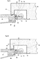
- Figs. 3A through 4B show a door or a window having latch arrangement 101 according to another example, configured for fastening a panel 100 to the frame element 102.
- the panel is a panel of a hinged door and is configured to abut, in the closed state thereof, against a shoulder portion 104 defined on the frame element 102, which includes a housing 105 for holding therein the latch arrangement 101.
- the panel includes a handle 132, pivotally mounted in close proximity to the end thereof, and is configured to allow opening of the panel 100 as explained hereinafter in detail.
- the latch arrangement 101 includes a locking element 108 pivotally mounted on the frame element 102 and is displaceable between a locked position, as shown in Fig. 3B , and an unlocked position shown in Figs. 3D, and 3E .
- the latch arrangement 101 includes a stop latch 120 selectively deployable to secure the locking element 108 in the locked position.
- actuating the locking element 108 and the stop latch 120 can be carried out either by a manual actuator 137 pivotally mounted on the door panel 100, or by a rotating actuator 117 mounted inside the housing 105.
- the stop latch 120 is configured to secure the locking element 108 by engaging a catch member on the manual actuator 137, which is mounted to the panel 100.
- the stop latch 70 is configured to secure the locking element 58 by engaging an abutment feature mounted on the frame element 12.
- rotating actuator 117 can be replaced with a linear actuator configured to pivot the stop latch 120 and the locking element 108.
- the locking element 108 includes a first end 114 configured to engage a depression 110 defined on the frame facing portion 107 of the door panel 100, and a second end 116 affixed to the frame element 102. As shown in Fig. 3B , in the locked position, the locking element 108 is pivoted towards the panel 100 and is disposed at an oblique angle with respect to the panel 100.
- the stop latch 120 is pivotally mounted on the locking element 108 and includes a tail portion 122 extending into the housing 105 and configured to engage the rotating actuator 117 mounted inside the housing 105.
- the locking element 108 includes a hook 128 defined on an end of the stop latch 120 opposing the tail portion 122 and extending towards the frame facing portion 107.
- the hook 128 is configured to engage a catch member 138 defined on the manual actuator 137 of the panel 1 00, such that the locking element 108 is secured in the locked position thereof.
- the stop latch 120 is configured to pivot between a secured position, in which the locking element 108 is secured in the locked position thereof by the engagement of the hook 128 with the catch member 138, and a released position in which the locking element 108 is free to pivot towards the housing 105 disengaging thereby the cutaway depression 110 of the panel 100.
- the latch arrangement 101 includes rotating actuator 117 mounted inside the housing 105.
- the rotating actuator 117 is configured to selectively rotate in a first and a second direction in a motion parallel to the pivoting motion of the stop latch 120, while engaging the tail portion 122 of the stop latch 120.
- the pivoting angle of the stop latch 120 can be limited by engagement with the locking element 108, such that further rotation of the rotating actuator 117 in the first direction urges the locking element 108 to pivot away from the depression 110 to the unlocked position thereof, as shown in Fig. 3D .
- the door panel 100 can be pulled by the handle 132 to the opened state thereof.
- the rotating actuator 117 can be rotated in a second direction, such that the tail portion 122 of the stop latch 120 can be pivoted back to the secured position and the locking element 108 is pivoted back to the locked positon. It is appreciated that the pivoting of the stop latch 120 and the locking element 108 back to the secured and locked position, respectively, can be carried out by a return mechanism, such as a spring (not shown), etc. Accordingly, the rotating actuator 117 is configured to oppose the force of such return mechanism when the rotating actuator 117 is rotated in the first direction. When the rotating actuator 117 is rotated in the first direction however, the stop latch 120 and the locking element 108 are urged back to the secured and locked position, respectively, by the forces of the return mechanism.
- actuating the locking element 108 and the stop latch 120 can be carried out by means of a manual actuator 137 pivotally mounted on the door panel 100.
- the manual actuator 137 can be integrally formed with a handle 132 including a grip 135 and the manual actuator 137.
- the handle 132 can be configured to pivot on the panel 100 about a pivoting point 134 defined between the grip 135 and a manual actuator 137.
- the manual actuator 137 is configured to engage a recess 112 defined on the locking element 108 in the locked position, as shown in Fig. 3B .
- the actuating mechanism for displacing the locking element between the locked and unlocked position includes a manual actuator 137 and a rotating actuator 117. It is appreciated that the manual actuator 137 and the rotating actuator 117 can operate independently from one another.
- Figs. 4A and 4B Attention is now directed to Figs. 4A and 4B , in which the operation of the manual actuator 137 is illustrated.
- the handle 132 can be pivoted towards an opening direction of the panel 100, causing thereby the manual actuator 137 to slide out of the recess 1 12 disengaging thereby the catch member 138 from the hook 128, such that the locking element 108 is no longer secured by the stop latch 120 and the catch member 138.
- Fig. 4B further pivoting of the handle 132 towards an opening direction of the panel 100, causes the manual actuator 137 to push the locking element 108 away from the depression 110 to the unlocked position.
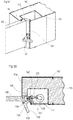
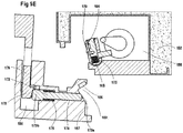
- a latch arrangement 151 can be implemented for fastening a panel 150 of a panic door to a frame element 152.
- the panel 150 is a panel of a hinged door and is configured to abut, in the closed state thereof, against a shoulder portion 154 defined on the frame element 152 which includes a housing 155 for holding therein the latch arrangement 151.
- the panel 150 includes a handle 162, pivotally mounted on the panel 150, and including a panic bar 164 horizontally extending along the panel 150.
- the panic door can be configured for an outdoor opening direction, such that pushing of the panic bar 164 in an opening direction of the door initiates the opening of the panel 150, as explained hereinafter.
- the latch arrangement 151 includes a locking element 158 pivotally mounted on the frame clement 152 and displaceable between a locked position, as shown in Fig. 5B , and an unlocked position shown in Figs. 5D , and 3E .
- the latch arrangement 151 includes a stop latch 160 selectively deployable to secure the locking element 158 in the locked position.
- the stop latch 160 is slidably mounted inside the locking element 158 and is configured to slide between a secured position in which at least one of the stop latch 160 is engaged with an abutment feature in a form of a recess 156, and a released position in which at least one portion of the stop latch 160 is retracted away from the recess 156.
- the abutment feature i.e. the recess 156 is defined on the panel 150, as explained hereinafter, this is as opposed to the example of Figs. 2A to 2E in which the abutment feature 74 is mounted on the frame element.
- the locking element 158 includes a first end 166 configured to engage a depression 159 defined on the frame facing portion 157 of the door panel 150, and a second end 168 affixed to the frame element 152. As shown in Fig. 5B , in the locked position, the locking element 158 is pivoted towards the panel 150 and is disposed at an oblique angle with respect to the panel 150.
- the stop latch 160 is slidably mounted inside the locking element 158 and is configured to selectively slide between a secured position in which at least an engaging portion 165 thereof protrudes from the first end 166 of the locking element 158, and a released position in which the stop latch 160 is retracted inside the locking element 158.
- the stop latch 160 can be spring biased by a spring member 175 mounted inside the locking element 158, and is configured to urge the stop latch 160 to the secured position, i.e. the engaging portion 165 protrudes from the first end 166.
- the recess 156 is configured as a recess formed inside the cutaway depression 159, and configured to engage with the engaging portion 165 of the stop latch 160.
- the locking element 158 can be pivoted to the locked position in which the first end 166 thereof is engaged with the cutaway depression 159 on the door panel 150.
- the stop latch 160 can be shifted to the secured position thereof, in which the engaging portion 165 protrudes from the first end 166, such that it engages the recess 156 formed inside the cutaway depression 159 precluding thereby the pivoting of the locking element 158 away from the depression 159 to the unlocked position.
- the locking element 158 further includes a pivot arm 1 70 pivotally mounted thereon and being coupled to the stop latch 160, such that when the pivot arm 170 is pivoted towards the locking element 158, the stop latch 160 is urged to slide towards the inside the locking element 158 to the released position, the purpose of the pivot arm 170 is explained herein below.
- the latch arrangement 151 further includes an actuating mechanism 180, having an actuating member, here illustrated as an actuating pin 172 slidably disposed inside a groove 174 defined the panel 150 and having a first end terminating at the frame facing portion 157 of the door panel 150, and a second end terminating at a hollow portion 184 defined inside the panel 150.
- the groove 174 according to the illustrated example is so defined such that, when the panel 150 is in the closed state thereof, the groove 174 coaxially disposed with the pivot arm 170 of locking element 158.
- the actuating pin 172 is thus configured to slide inside the groove 174 between the first and second ends of the groove 174, towards and away from the outer surface of the frame facing portion 157, such that the first end 173a thereof can selectively engage the pivot arm 170. As shown in Fig. 5B , the actuating pin 172 is disposed such that the second end 173b thereof is disposed inside the hollow portion 184, the purpose of which is explained hereinafter.
- the actuating pin 172 can be biased by a spring 175, such that is normally urged away from the outer surface of the frame facing portion 157. At this position, the pivot arm 170 is pivoted towards the first end of the groove 174.
- the actuating mechanism 180 can be manually operated by the handle 162 which, as noted above, includes a panic bar 164 pivotally mounted on the panel 150.
- the handle 162 can be displaceable between a first positon in which the locking element 158 is urged away from the depression 159 and a second position in which the locking element 158 is free to engage the depression 159.
- the handle 162 can include a pivoting mount 176, on which the panic bar 164 is mounted.
- the pivoting mount 176 is pivotally mounted on the door panel 150 and includes a sloped member 178 configured to pivot in and out of a hollow portion 184 formed inside the panel 150.
- the hollow portion 184 is defined such that the second end of the groove 174 is accessible through the hollow portion 184, and the second end 173b of the actuating pin 172 protrudes inside the hollow portion 184.
- the sloped member 178 of the pivoting mount 176 includes a portion having varying thickness so defined thereon such that when the sloped member 178 is pivoted inside the hollow portion 184 the sloped portion faces the second end of the groove 174 and engages the second end 173b of the actuating pin 172, which as indicated above is disposed in the hollow portion 184.
- the sloped member 178 selectively urges the actuating pin 172 to slide inside the groove 174 towards the frame facing portion 157 pushing thereby the pivot arm 170 to pivot and displace the stop latch 160 to the release position.
- Further pushing of the panic bar 164 causes the sloped member 178 to further pivot into the hollow portion 184 and the actuating pin 172 to further slide inside the groove 174.
- the further displacement of the pivot arm 170 in limited by the locking element 158 thus further displacement of the pivot arm 170 by the actuating pin 172 causes the locking clement 158 to pivot away from the cutaway depression 159.
- the spring 175 of the actuating pin 172 biases the actuating pin 172 such that it is retracted back toward the hollow portion 184, and the allowing the pivot arm 170 to pivot back and displace the stop latch 160 to the secured position in which the engaging portion 165 of the stop latch 160 engages the recess 156 formed inside the cutaway depression 159 precluding thereby the pivoting of the locking element 158 away from the depression 159 to the unlocked positon.
- Figs. 6A to 6E show a latch arrangement 201 configured for fastening a panel 200 of a sliding door to a frame element 202, this is as opposed to the previous example, in which the panel is a panel of a hinged door.
- the latch arrangement 201 includes a locking element 210 pivotally mounted on the frame element 202 and an actuating mechanism including a manually operable handle 212 mounted on the panel 200 and being configured to interact with the locking element 210 to lock the panel to the frame element 202.
- the frame element 202 includes a first side portion 204a coupled to a second side portion 204b and being spaced apart from the first side portion 204a defining thereby a housing 206 therebetween.
- the housing 206 is configured for receiving therein an end segment of the panel 200.
- the frame element 202 further includes an abutting portion 208 transversely extending inside the housing 206 from the first side portion 204a defining an opening 205 between an edge thereof and the second side portion 204b.
- the opening 205 is configured to allow sliding of the end segment of the panel 200 therethrough into the housing 206.
- the panel 200 can include a depression having shoulder portion 209 protruding from the surface of the panel 200 towards the first side portion 204a of the frame element 202.
- the locking element 210 include a first end 212a and a second end 212b, and is disposed in the housing 206 and displaceable between a locked position ( Figs. 6A and 6B ) and an unlocked positon ( Figs. 6D and 6E ).
- a locked position Figs. 6A and 6B
- an unlocked positon Figs. 6D and 6E
- the first end 212a of the locking element 210 is engaged with shoulder portion 209 of the panel 200
- the second end 212b is engaged with the abutting portion 208 of the frame element 202 precluding thereby the sliding of the panel 200 out of the housing 206.
- the locking element 210 In the unlocked position the locking element 210 is pivoted such that the first end 212a of the locking element 210 is disengaged from the shoulder portion 209 of the panel 200 such the panel 200 is free to be slid away from the frame element 202 to the open state thereof.
- the locking element 210 in the locked position is extended at an oblique angle with respect to the panel 200 such that the first end 212a is engaged with the shoulder portion 209 which can also be formed with a corresponding angle.
- the locking element 210 in the locked position of the locking element 210 the displacement of the panel 200 towards an opening direction of the panel is opposed by compressive forces exerted between the locking element 208 and the butting portion 208 of the frame element 202.
- the latch arrangement 201 can further include a positive lock member 215 pivotally mounted inside the housing 208 and having a first arm 216a and a second arm 216b.
- the first arm 216a is configured to engage an edge of the panel 200 when in the closed state
- the second arm 216b is configured to engage a surface of the locking element 210.
- the positive lock member 215 is configured such the when the panel 200 is slid into the housing 208 to the closed state thereof, the edge of the panel 200 engages the first arm 216a and pushes it in a direction parallel to the closing direction of the panel 200.
- the positive lock member 215 is pivoted and the second arm 216b urges the locking element 210 to the locked position, i.e. the first end 212a is engaged with the shoulder portion 209.
- the positive lock member 215 allows an autonomous displacement of the locking element 210 to the locked position thereof upon closing of the door panel 200.
- the positive lock member 215 is an optional element, and the latch arrangement 201 according to other examples include a return mechanism configured to urge the locking element 210 to the locked position thereof.
- the latch arrangement 201 further includes a stop latch 218 selectively deployable to secure the locking element 210 in the locked position.
- the stop latch 218 is slidably mounted inside the locking element 210 and include a hook portion 220a defined on one end thereof and an engaging portion 220b defined on an opposing end thereof.
- the stop latch 218 is configured to slide inside the locking element 210 while the hook portion 220a is disposed on one side of the locking element 210 while the engaging portion 220b is disposed on a second side of the locking element 210.
- the stop latch 218 is configured to slide between a secured position in which the hook portion 220a is engaged with an abutment feature in a form of a catch member 224 on the frame element 202, and a released position in which the hook portion 220a is disengaged from the catch member 224.
- the hook portion 220a of the stop latch 218 and the catch member 224 on the frame element 202 are configured to be engaged to one another when the locking element 210 is pivoted to the locked position thereof. That is to say, catch member 224 on the frame element 202 is disposed in parallel with the sliding axis of the stop latch 218, when the locking element 210 is in the locked position. This way, at this position, as shown in Figs.
- the stop latch 218 can be selectively slid between a secured position in which the hook portion 220a is engaged with the catch member 224 on the frame element 202, precluding thereby the pivoting of the locking element 210 to the unlocked position thereof, and a released position in which the hook portion 220a is disengaged from the catch member 224, and the locking element 210 is free to pivot to the unlocked position thereof.
- the catch member 224 is no longer parallel to the sliding axis of the stop latch 218 and the hook portion 220a can no longer be engaged with the catch member 224, as shown in Fig. 6D .
- the panel 200 can be slid out of the housing 206 as shown in Fig. 6F .
- the stop latch 218 can be biased by a spring member 222 mounted inside the locking element 210 urging the stop latch 218 to the secured position thereof.
- the latch arrangement 201 further includes an actuating mechanism including a manually operable handle 212 mounted on the panel 200 and being configured to interact with the locking element 210 to lock the panel to the frame element 202.
- the handle 212 is pivotally mounted on the panel 200 and includes a grip 230 and an actuating member 232.
- the actuating member 232 is disposed in close proximity with the surface of the panel 200, while the grip 230 protrudes away from the surface of the panel 200 such that it can be griped.
- the handle 212 is mounted such that when the edge of the panel 200 is inserted inside the housing 206, the actuating member 232 is inserted therewith and is configured to engage the engaging portion 220b of the stop latch 218.
- the handle 212 can be pivoted between a first position in which the actuating member 232 is pivoted towards the surface of the panel 200 and a second position in which the actuating member 232 is pivoted away the surface of the panel 200.
- a first position in which the actuating member 232 is pivoted towards the surface of the panel 200
- a second position in which the actuating member 232 is pivoted away the surface of the panel 200.
- pivoting the handle 212 to the second position causes the actuating member 232 to engage the engaging portion 220b of the stop latch 218, and to urge the stop latch 218 to slide to the released position thereof.
- the hook portion 220a is disengaged from the catch member 224, and the locking element 210 is free to pivot to the unlocked position thereof.
- the handle 212 is so mounted on the panel 200. such that pivoting of the grip 230 towards an opening direction of the panel 200 causes the actuating member 232 to displace the stop latch 218 to the released position thereof. and the locking element 210 to the unlocked position thereof. This way, when it is desired to unlock and open the door panel 200 a single motion of pulling the grip 230 in one direction is required.
Landscapes
- Engineering & Computer Science (AREA)
- Structural Engineering (AREA)
- Mechanical Engineering (AREA)
- Physics & Mathematics (AREA)
- Electromagnetism (AREA)
- Business, Economics & Management (AREA)
- Emergency Management (AREA)
- Lock And Its Accessories (AREA)
Applications Claiming Priority (2)
| Application Number | Priority Date | Filing Date | Title |
|---|---|---|---|
| US15/059,363 US9988830B2 (en) | 2016-03-03 | 2016-03-03 | Latch arrangement having a handle |
| PCT/IL2017/050267 WO2017149544A1 (en) | 2016-03-03 | 2017-03-02 | Latch arrangement having a handle |
Publications (3)
| Publication Number | Publication Date |
|---|---|
| EP3423652A1 EP3423652A1 (en) | 2019-01-09 |
| EP3423652A4 EP3423652A4 (en) | 2019-04-03 |
| EP3423652B1 true EP3423652B1 (en) | 2020-12-30 |
Family
ID=59722682
Family Applications (1)
| Application Number | Title | Priority Date | Filing Date |
|---|---|---|---|
| EP17759386.0A Active EP3423652B1 (en) | 2016-03-03 | 2017-03-02 | Latch arrangement having a handle |
Country Status (9)
| Country | Link |
|---|---|
| US (1) | US9988830B2 (ja) |
| EP (1) | EP3423652B1 (ja) |
| JP (1) | JP7046371B2 (ja) |
| CN (1) | CN108699864B (ja) |
| AU (1) | AU2017228059B2 (ja) |
| CA (1) | CA3012090A1 (ja) |
| DK (1) | DK3423652T3 (ja) |
| IL (1) | IL261088B (ja) |
| WO (1) | WO2017149544A1 (ja) |
Families Citing this family (11)
| Publication number | Priority date | Publication date | Assignee | Title |
|---|---|---|---|---|
| US10865588B2 (en) | 2015-08-24 | 2020-12-15 | Dan Raz Ltd. | Securing mechanism for a sliding panel |
| IL241392B (en) | 2015-09-09 | 2021-05-31 | Dan Raz Ltd | Door with additional integration on the side of the hinge |
| US9970214B2 (en) | 2015-11-29 | 2018-05-15 | Dan Raz Ltd | Door or other closable panel with lock-actuating linkage |
| US10487545B2 (en) | 2016-03-03 | 2019-11-26 | Dan Raz Ltd. | Latch arrangement having a stop latch |
| US10982477B2 (en) * | 2017-06-09 | 2021-04-20 | Endura Products, Llc | Sliding door unit and components for the same |
| US11598125B2 (en) | 2017-09-03 | 2023-03-07 | Dan Raz Ltd. | Latch arrangement |
| DE102018200559B4 (de) * | 2018-01-15 | 2019-10-31 | Gebr. Willach Gmbh | Schiebetürsystem |
| IL281744B2 (en) * | 2018-09-23 | 2024-04-01 | Dan Raz Ltd | panel lock assembly |
| CA3125953A1 (en) * | 2019-01-15 | 2020-07-23 | Dan Raz Ltd. | Panel closure apparatus |
| ES2782050B2 (es) | 2019-03-08 | 2021-11-11 | Tecnologia Y Multihusillos S L | Dispositivo de cierre automatico y de apertura para puertas |
| US12077938B2 (en) * | 2021-10-12 | 2024-09-03 | Caterpillar Inc. | Secondary control system and method for mounting with service orientation |
Family Cites Families (117)
| Publication number | Priority date | Publication date | Assignee | Title |
|---|---|---|---|---|
| US435658A (en) | 1890-09-02 | Weather-strip | ||
| US313742A (en) | 1885-03-10 | Threshold | ||
| US868036A (en) | 1906-08-13 | 1907-10-15 | Clyde Tong | Window-catch. |
| US1231069A (en) | 1915-06-26 | 1917-06-26 | Gen Fire Proofing Company | Door-joint construction. |
| US1609342A (en) * | 1925-01-19 | 1926-12-07 | Alexander F Winters | Latch |
| US1973461A (en) | 1933-09-07 | 1934-09-11 | Elmer D Barringer | Weather strip |
| US2108965A (en) * | 1934-02-19 | 1938-02-22 | Gen Motors Corp | Latch |
| DE929592C (de) | 1943-03-26 | 1955-06-30 | Gertrud Haack | Verschluss fuer Gasschutztueren |
| US2572717A (en) | 1948-07-24 | 1951-10-23 | Mortimer A Gersten | Cabinet door construction |
| US2572117A (en) | 1949-11-29 | 1951-10-23 | George E Dennis | Dental bite matrix |
| US2579875A (en) | 1950-05-20 | 1951-12-25 | Stanko Lloyd | Door threshold |
| US2834066A (en) | 1953-12-21 | 1958-05-13 | Nile R Lybarger | Adjustable door jambs |
| US2812204A (en) * | 1955-02-14 | 1957-11-05 | Midwest Mfg Corp | Door lock |
| US2978757A (en) * | 1957-05-17 | 1961-04-11 | Spickelmier Ind Inc | Lock |
| US3019493A (en) | 1960-02-23 | 1962-02-06 | Victor L Walenga | Weatherseal for doors |
| US3002592A (en) | 1960-05-06 | 1961-10-03 | Bert A Quinn | Hinge and metallic frame construction |
| US3159093A (en) | 1961-10-09 | 1964-12-01 | Morton M Rosenfeld | Door structure |
| US3172168A (en) | 1962-05-31 | 1965-03-09 | Stanley Works | Retractable door stop |
| US3222098A (en) * | 1963-09-24 | 1965-12-07 | Gerald E Hausfeld | Automatic window lock |
| US3634962A (en) | 1969-07-03 | 1972-01-18 | Martin E Peterson | Integral interlocking weather stripping for doors, doorjambs and thresholds |
| DE2121686A1 (de) | 1971-05-03 | 1972-11-16 | Martin Fiala Kg, 7015 Korntal | Container |
| US3877282A (en) | 1972-04-26 | 1975-04-15 | Texaco Inc | Swaging tool for joining two telescopic pipe ends |
| GB1399058A (en) * | 1973-04-07 | 1975-06-25 | Overton Ltd Wilfred | Latches |
| US3877262A (en) * | 1973-09-20 | 1975-04-15 | Emhart Corp | Emergency exit latch and actuator assembly |
| US3872696A (en) | 1973-10-15 | 1975-03-25 | Arthur V Geringer | Combination lock and fail-safe latch for exit doors |
| US4004629A (en) | 1974-10-09 | 1977-01-25 | Kelly Donald V | Frameless sliding window assembly |
| US3959927A (en) * | 1974-12-04 | 1976-06-01 | Zephyr Aluminum, Incorporated | Sealing assembly |
| US3973794A (en) * | 1975-04-30 | 1976-08-10 | Leonard Green | Interior door latch assembly |
| AT352976B (de) | 1975-06-26 | 1979-10-25 | Ginther Philipp | Fenster, tuere od.dgl. |
| US4045065A (en) | 1975-11-06 | 1977-08-30 | Lawrence Brothers, Inc. | Releasable door stop and strike plate assembly for a bidirectional swinging door |
| GB1538297A (en) * | 1975-11-21 | 1979-01-17 | Access Control Syst | Door lock apparatus |
| US4062576A (en) | 1976-05-10 | 1977-12-13 | Robert Newton Jennings | Sliding glass window and door lock |
| DE2639691C3 (de) | 1976-09-03 | 1981-01-08 | Bochumer Eisenhuette Heintzmann Gmbh & Co, 4630 Bochum | Schutztür |
| CA1029063A (en) | 1976-09-15 | 1978-04-04 | Labra-Door Limited | Latch for sliding sash window |
| US4106239A (en) | 1977-03-15 | 1978-08-15 | Croft Metals, Inc. | Lockable window construction |
| DE2719374C3 (de) | 1977-04-30 | 1980-12-04 | Tivadar 7130 Muehlacker Hoffmann | Zusatzfenster |
| US4203255A (en) | 1977-05-26 | 1980-05-20 | Cal-Wood Door | Fire-resistant composite wood structure particularly adapted for use in fire doors |
| US4133142A (en) | 1977-10-11 | 1979-01-09 | Dzus Fastener Co., Inc. | Latch |
| US4110867A (en) | 1977-11-14 | 1978-09-05 | Mckinney Manufacturing Company | Retractable door stop for bidirectional swinging door |
| US4180287A (en) | 1978-04-06 | 1979-12-25 | Southern Steel Company | Cell locking system |
| US4230351A (en) | 1978-05-15 | 1980-10-28 | Southco, Inc. | Link and lever operated toggle latch mechanism |
| US4216986A (en) | 1978-08-09 | 1980-08-12 | Lawrence Brothers, Inc. | Releasable door stop assembly |
| US4367610A (en) | 1979-04-10 | 1983-01-11 | John Mowlem & Company Limited | Door opening and closing mechanism |
| US4300795A (en) | 1979-09-10 | 1981-11-17 | Jennings Robert N | Sliding glass window and door lock apparatus including lock unit with dual spring biased eccentrics |
| US4441277A (en) | 1979-12-26 | 1984-04-10 | Naylor Donald B | Invertible prefabricated door |
| EP0067065B1 (en) | 1981-06-10 | 1987-01-28 | Hitachi, Ltd. | Electromagnetic-acoustic measuring apparatus |
| US4428153A (en) * | 1982-03-08 | 1984-01-31 | Atlanta Richfield Company | Recessed astragal for double door |
| US4534587A (en) * | 1983-01-28 | 1985-08-13 | W & F Manufacturing, Inc. | Latch assembly |
| GB2154639B (en) | 1984-02-11 | 1987-06-03 | Chubb Security Projects | Door |
| DE3447796A1 (de) | 1984-12-29 | 1986-07-10 | Oskar D. Biffar Gmbh + Co Kg, 6732 Edenkoben | Vorrichtung zum sicheren verschliessen von haustueren |
| GB2195958B (en) | 1986-09-27 | 1990-11-07 | Leith Cardle & Co Ltd | A door for bulkheads |
| EP0270437B1 (fr) * | 1986-11-18 | 1990-02-07 | Chateau, Michel Marie | Dispositif de condamnation de porte |
| US4765662A (en) | 1986-12-30 | 1988-08-23 | Suska Charles R | Coordinated door stop and latch |
| FR2631068B1 (fr) | 1988-05-03 | 1994-12-02 | Ferco Int Usine Ferrures | Ferrure de verrouillage, notamment, pour ouvrant coulissant |
| DE8900012U1 (de) | 1988-05-17 | 1989-03-02 | Ingenieur Klaus Blaurock Bau- und Raumtechnik, 8741 Salz | Schutzvorrichtung für die Drehbänder einer Sicherheitstür für Gebäude |
| US4831779A (en) | 1988-08-31 | 1989-05-23 | Schlegel Corporation | Self-draining panel threshold combination |
| GB2233701B (en) | 1989-06-29 | 1993-08-25 | Uniqey | A door locking arrangement |
| AU627346B2 (en) | 1989-08-18 | 1992-08-20 | Alchin & Long Group Pty Limited | Locking device for sliding sash |
| US5137327A (en) | 1990-09-27 | 1992-08-11 | Edmonds R Michael | Vehicle vent and escape hatch |
| AU641561B2 (en) | 1990-10-31 | 1993-09-23 | Alchin & Long Group Pty Limited | Locking mechanism for sliding sash windows |
| GB2250772A (en) | 1990-11-24 | 1992-06-17 | Group Sales Limited | Locking mechanisms |
| US5224297A (en) | 1991-06-10 | 1993-07-06 | Nelson A. Taylor Co., Inc. | Sliding door and latching/locking assembly |
| US5172520A (en) * | 1991-09-16 | 1992-12-22 | Vinyl Tech | Window assembly having a horizontally slidable window unit latchable in a closed position |
| US5403047A (en) * | 1993-01-11 | 1995-04-04 | Walls; Donald L. | Door lock apparatus |
| US5349782A (en) * | 1993-03-08 | 1994-09-27 | Yulkowski Leon B | Door construction having improved locking assembly |
| US5326141A (en) * | 1993-06-22 | 1994-07-05 | Milgard Manufacturing, Inc. | Retractable, self-locking window latch |
| US5409272A (en) | 1993-06-28 | 1995-04-25 | Southco, Inc. | Over-center latch assembly |
| US5465460A (en) | 1994-08-29 | 1995-11-14 | Cantone; Giovanni | Doorstop |
| GB9418787D0 (en) | 1994-09-17 | 1994-11-02 | Doors Limited | Improvements in and relating to security of buildings and other structures |
| US6497073B2 (en) | 1995-10-19 | 2002-12-24 | Stephen Robert Webb | Door safety device |
| DE29517077U1 (de) | 1995-10-28 | 1997-02-27 | Mundhenke, Erich, 31848 Bad Münder | Sicherheitstür mit beidseitiger auf der gesamten Türhöhe durchgehender Verriegelung |
| NZ299260A (en) * | 1996-08-29 | 1999-01-28 | Interlock Group Ltd Substitute | Window fastener includes a sash window which automatically locks when moved to closed position and has biased latching means coupled to a handle |
| JPH10196190A (ja) * | 1997-01-06 | 1998-07-28 | Miyuki Takasu | 家具の開閉部材の係止機構 |
| US5927773A (en) * | 1997-02-19 | 1999-07-27 | Tri/Mark Corporation | Latch assembly for movable closure |
| US5931415A (en) | 1997-05-09 | 1999-08-03 | The Boeing Company | Plug-type overwing emergency exit door assembly |
| US6185871B1 (en) | 1999-02-09 | 2001-02-13 | Hui-Tung Wang | Door structure |
| US6286274B1 (en) | 1999-04-13 | 2001-09-11 | Therma-Tru Virginia Company Incorporated Llc | Clip mounting system for door frame |
| US6409234B1 (en) * | 1999-11-12 | 2002-06-25 | Tri/Mark Corporation | Latch assembly for a movable closure |
| US6564428B2 (en) | 2000-01-14 | 2003-05-20 | Hoffman Enclosures, Inc. | Compound hinge |
| US20020095885A1 (en) | 2001-01-24 | 2002-07-25 | Sampson Kenneth E. | Force resistant door and window framing system |
| DE10117173B4 (de) | 2001-04-06 | 2007-10-04 | Biffar Gmbh | Tür |
| US7090263B2 (en) | 2001-05-04 | 2006-08-15 | Spx Corporation | Door latching device and method |
| DE20108954U1 (de) | 2001-05-29 | 2002-10-10 | Ramsauer, Dieter, 42555 Velbert | Stangenverschluß |
| JP3951172B2 (ja) * | 2002-06-14 | 2007-08-01 | 豊和工業株式会社 | 扉の閉鎖機構 |
| DE20210019U1 (de) | 2002-06-28 | 2002-10-24 | Ries, Ernst, 36154 Hosenfeld | Vorrichtung zum Sichern eines Verschlussteiles |
| EP1422368A1 (en) | 2002-11-19 | 2004-05-26 | Rosengrens Benelux B.V. | Lock |
| JP4161306B2 (ja) * | 2003-03-05 | 2008-10-08 | 豊和工業株式会社 | 扉の閉鎖装置 |
| EP1475494A3 (en) * | 2003-05-09 | 2009-12-16 | HONDA MOTOR CO., Ltd. | Door handle device for vehicles |
| DE10322798A1 (de) | 2003-05-19 | 2004-12-09 | W.A.S. Technologies Gmbh | Rohrverriegelung |
| DE20316663U1 (de) * | 2003-10-29 | 2004-01-08 | Böllhoff GmbH | Schloss mit lösbarer Verrastung |
| US7313937B2 (en) * | 2004-02-22 | 2008-01-01 | Southco, Inc. | Latch |
| JP4515118B2 (ja) | 2004-03-12 | 2010-07-28 | 日東電工株式会社 | 透明両面粘着テープ又はシート及びタッチパネル |
| US7000550B1 (en) | 2004-05-03 | 2006-02-21 | Mandall Michael C | Ablative blast resistant security door panel |
| US7269984B2 (en) | 2004-07-31 | 2007-09-18 | Southco, Inc. | Ratcheting pawl latch |
| AT501292B8 (de) | 2005-03-18 | 2007-02-15 | Dorma Gmbh & Co Kg | Rahmenlose glastüre |
| JP4651428B2 (ja) | 2005-03-28 | 2011-03-16 | ローム株式会社 | スイッチングレギュレータ及びこれを備えた電子機器 |
| FR2890644B1 (fr) | 2005-09-15 | 2007-11-02 | Aircelle Sa | Dispostif d'accrochage a autoverrouillage dynamique |
| FR2891295B1 (fr) | 2005-09-26 | 2009-02-06 | Stremler Soc Par Actions Simpl | Dispositif de verrouillage pour fenetre, porte ou porte-fenetre coulissante |
| US8627606B2 (en) | 2005-12-30 | 2014-01-14 | Tyto Life LLC | Combined sealing system for garage door |
| US8925249B2 (en) | 2006-06-20 | 2015-01-06 | Tyto Life LLC | Active sealing and securing systems for door/window |
| US8182001B2 (en) * | 2006-09-14 | 2012-05-22 | Milgard Manufacturing Incorporated | Direct action window lock |
| US8146393B2 (en) * | 2008-02-19 | 2012-04-03 | Kabushiki Kaisha Tokai Rika Denki Seisakusho | Vehicle door handle device |
| US20090289065A1 (en) | 2008-05-22 | 2009-11-26 | Sampson Kenneth E | Blast and explosion retaining system for doors |
| CN102034522B (zh) * | 2009-09-30 | 2012-09-19 | 鸿富锦精密工业(深圳)有限公司 | 卡锁结构 |
| US8707625B2 (en) | 2011-06-28 | 2014-04-29 | Dan Raz Ltd. | Arrangement for securing a panel closure |
| DE112012003202T5 (de) * | 2011-08-02 | 2014-04-17 | Piolax Inc. | Verriegelungsvorrichtung für Öffnungs-/Schließelement |
| JP2013104235A (ja) * | 2011-11-15 | 2013-05-30 | Miwa Lock Co Ltd | 内外気圧差解消装置 |
| JP5734219B2 (ja) * | 2012-02-09 | 2015-06-17 | 株式会社ホンダロック | 車両用ドアのラッチ解除装置 |
| US8813427B2 (en) | 2012-05-17 | 2014-08-26 | Quanex Corporation | Threshold assembly having a rail and a drainage element |
| JP6096008B2 (ja) * | 2013-03-12 | 2017-03-15 | 株式会社アルファ | 操作ケーブルの配索構造 |
| US9273486B2 (en) * | 2013-03-15 | 2016-03-01 | Milgard Manufacturing Incorporated | Continuous handle for window |
| JP6131103B2 (ja) * | 2013-05-24 | 2017-05-17 | 株式会社アルファ | 車両用ハンドル装置 |
| KR102084382B1 (ko) * | 2013-11-05 | 2020-03-04 | 현대모비스 주식회사 | 차량용 글로브 박스의 손잡이 구조 |
| GB201320870D0 (en) | 2013-11-26 | 2014-01-08 | Einstein Ip Ltd | A locking device |
| JP6399291B2 (ja) * | 2014-07-30 | 2018-10-03 | アイシン精機株式会社 | 車両用ドアハンドル装置 |
| US9970221B2 (en) * | 2014-09-12 | 2018-05-15 | Hyundai Motor Company | Door handle assembly for motor vehicle |
| US9605444B2 (en) * | 2014-09-23 | 2017-03-28 | Amesbury Group, Inc. | Entry door latch actuator system |
-
2016
- 2016-03-03 US US15/059,363 patent/US9988830B2/en active Active
-
2017
- 2017-03-02 JP JP2018536845A patent/JP7046371B2/ja active Active
- 2017-03-02 CA CA3012090A patent/CA3012090A1/en not_active Withdrawn
- 2017-03-02 CN CN201780011710.6A patent/CN108699864B/zh active Active
- 2017-03-02 WO PCT/IL2017/050267 patent/WO2017149544A1/en active Application Filing
- 2017-03-02 EP EP17759386.0A patent/EP3423652B1/en active Active
- 2017-03-02 DK DK17759386.0T patent/DK3423652T3/da active
- 2017-03-02 AU AU2017228059A patent/AU2017228059B2/en active Active
-
2018
- 2018-08-09 IL IL261088A patent/IL261088B/en unknown
Non-Patent Citations (1)
| Title |
|---|
| None * |
Also Published As
| Publication number | Publication date |
|---|---|
| JP7046371B2 (ja) | 2022-04-04 |
| AU2017228059B2 (en) | 2021-09-02 |
| US9988830B2 (en) | 2018-06-05 |
| EP3423652A1 (en) | 2019-01-09 |
| IL261088A (en) | 2018-10-31 |
| WO2017149544A1 (en) | 2017-09-08 |
| EP3423652A4 (en) | 2019-04-03 |
| IL261088B (en) | 2021-07-29 |
| AU2017228059A1 (en) | 2018-07-26 |
| CA3012090A1 (en) | 2017-09-08 |
| US20170254125A1 (en) | 2017-09-07 |
| DK3423652T3 (da) | 2021-03-29 |
| CN108699864B (zh) | 2021-03-30 |
| CN108699864A (zh) | 2018-10-23 |
| JP2019510897A (ja) | 2019-04-18 |
Similar Documents
| Publication | Publication Date | Title |
|---|---|---|
| EP3423652B1 (en) | Latch arrangement having a handle | |
| US11359412B2 (en) | Latch arrangement having a stop latch | |
| US8646815B2 (en) | Gate latch | |
| US11598125B2 (en) | Latch arrangement | |
| JP2019507256A5 (ja) | ||
| TWI666368B (zh) | 具有斜閉塞面之柱形閂鎖螺栓組裝件 | |
| US8146961B2 (en) | Exit device | |
| TWI666372B (zh) | 藉由繞第一軸線或第二軸線樞轉致動器的可操作鎖固式鎖具 | |
| NZ233276A (en) | Latching window stay | |
| CA2875425C (en) | Multi-point lock assembly | |
| TWM487341U (zh) | 汽車門鎖的解鎖機構 | |
| TWI512181B (zh) | 汽車門鎖的解鎖機構 | |
| EP3911821B1 (en) | Panel closure apparatus | |
| AU2004100601A4 (en) | Deadlock with privacy function | |
| AU2020204253A1 (en) | Double door lock assembly |
Legal Events
| Date | Code | Title | Description |
|---|---|---|---|
| STAA | Information on the status of an ep patent application or granted ep patent |
Free format text: STATUS: THE INTERNATIONAL PUBLICATION HAS BEEN MADE |
|
| PUAI | Public reference made under article 153(3) epc to a published international application that has entered the european phase |
Free format text: ORIGINAL CODE: 0009012 |
|
| STAA | Information on the status of an ep patent application or granted ep patent |
Free format text: STATUS: REQUEST FOR EXAMINATION WAS MADE |
|
| 17P | Request for examination filed |
Effective date: 20180828 |
|
| AK | Designated contracting states |
Kind code of ref document: A1 Designated state(s): AL AT BE BG CH CY CZ DE DK EE ES FI FR GB GR HR HU IE IS IT LI LT LU LV MC MK MT NL NO PL PT RO RS SE SI SK SM TR |
|
| AX | Request for extension of the european patent |
Extension state: BA ME |
|
| A4 | Supplementary search report drawn up and despatched |
Effective date: 20190228 |
|
| RIC1 | Information provided on ipc code assigned before grant |
Ipc: E05C 3/16 20060101ALI20190222BHEP Ipc: E05B 65/10 20060101ALN20190222BHEP Ipc: E05B 63/00 20060101AFI20190222BHEP Ipc: E05B 63/24 20060101ALI20190222BHEP Ipc: E05B 65/00 20060101ALN20190222BHEP Ipc: E05B 65/08 20060101ALI20190222BHEP Ipc: E05B 17/20 20060101ALI20190222BHEP Ipc: E05C 1/12 20060101ALI20190222BHEP Ipc: E05C 19/00 20060101ALN20190222BHEP |
|
| DAV | Request for validation of the european patent (deleted) | ||
| DAX | Request for extension of the european patent (deleted) | ||
| RIC1 | Information provided on ipc code assigned before grant |
Ipc: E05B 17/20 20060101ALI20191127BHEP Ipc: E05B 65/08 20060101ALI20191127BHEP Ipc: E05C 1/12 20060101ALI20191127BHEP Ipc: E05B 63/24 20060101ALI20191127BHEP Ipc: E05B 63/00 20060101AFI20191127BHEP Ipc: E05B 65/10 20060101ALN20191127BHEP Ipc: E05C 19/00 20060101ALN20191127BHEP Ipc: E05B 65/00 20060101ALN20191127BHEP Ipc: E05C 3/16 20060101ALI20191127BHEP |
|
| GRAP | Despatch of communication of intention to grant a patent |
Free format text: ORIGINAL CODE: EPIDOSNIGR1 |
|
| STAA | Information on the status of an ep patent application or granted ep patent |
Free format text: STATUS: GRANT OF PATENT IS INTENDED |
|
| RIC1 | Information provided on ipc code assigned before grant |
Ipc: E05C 19/00 20060101ALN20191206BHEP Ipc: E05B 65/00 20060101ALN20191206BHEP Ipc: E05B 17/20 20060101ALI20191206BHEP Ipc: E05C 3/16 20060101ALI20191206BHEP Ipc: E05C 1/12 20060101ALI20191206BHEP Ipc: E05B 65/10 20060101ALN20191206BHEP Ipc: E05B 63/24 20060101ALI20191206BHEP Ipc: E05B 65/08 20060101ALI20191206BHEP Ipc: E05B 63/00 20060101AFI20191206BHEP |
|
| INTG | Intention to grant announced |
Effective date: 20200114 |
|
| GRAJ | Information related to disapproval of communication of intention to grant by the applicant or resumption of examination proceedings by the epo deleted |
Free format text: ORIGINAL CODE: EPIDOSDIGR1 |
|
| STAA | Information on the status of an ep patent application or granted ep patent |
Free format text: STATUS: REQUEST FOR EXAMINATION WAS MADE |
|
| STAA | Information on the status of an ep patent application or granted ep patent |
Free format text: STATUS: EXAMINATION IS IN PROGRESS |
|
| INTC | Intention to grant announced (deleted) | ||
| 17Q | First examination report despatched |
Effective date: 20200319 |
|
| RIC1 | Information provided on ipc code assigned before grant |
Ipc: E05C 1/12 20060101ALI20200623BHEP Ipc: E05B 65/10 20060101ALN20200623BHEP Ipc: E05B 65/00 20060101ALN20200623BHEP Ipc: E05B 17/20 20060101ALI20200623BHEP Ipc: E05C 3/16 20060101ALI20200623BHEP Ipc: E05C 19/00 20060101ALN20200623BHEP Ipc: E05B 63/00 20060101AFI20200623BHEP Ipc: E05B 63/24 20060101ALI20200623BHEP Ipc: E05B 65/08 20060101ALI20200623BHEP |
|
| GRAP | Despatch of communication of intention to grant a patent |
Free format text: ORIGINAL CODE: EPIDOSNIGR1 |
|
| STAA | Information on the status of an ep patent application or granted ep patent |
Free format text: STATUS: GRANT OF PATENT IS INTENDED |
|
| RIC1 | Information provided on ipc code assigned before grant |
Ipc: E05B 65/08 20060101ALI20200721BHEP Ipc: E05B 63/24 20060101ALI20200721BHEP Ipc: E05B 65/10 20060101ALN20200721BHEP Ipc: E05B 65/00 20060101ALN20200721BHEP Ipc: E05C 19/00 20060101ALN20200721BHEP Ipc: E05C 3/16 20060101ALI20200721BHEP Ipc: E05C 1/12 20060101ALI20200721BHEP Ipc: E05B 63/00 20060101AFI20200721BHEP Ipc: E05B 17/20 20060101ALI20200721BHEP |
|
| INTG | Intention to grant announced |
Effective date: 20200803 |
|
| GRAS | Grant fee paid |
Free format text: ORIGINAL CODE: EPIDOSNIGR3 |
|
| GRAA | (expected) grant |
Free format text: ORIGINAL CODE: 0009210 |
|
| STAA | Information on the status of an ep patent application or granted ep patent |
Free format text: STATUS: THE PATENT HAS BEEN GRANTED |
|
| AK | Designated contracting states |
Kind code of ref document: B1 Designated state(s): AL AT BE BG CH CY CZ DE DK EE ES FI FR GB GR HR HU IE IS IT LI LT LU LV MC MK MT NL NO PL PT RO RS SE SI SK SM TR |
|
| REG | Reference to a national code |
Ref country code: GB Ref legal event code: FG4D |
|
| REG | Reference to a national code |
Ref country code: AT Ref legal event code: REF Ref document number: 1350068 Country of ref document: AT Kind code of ref document: T Effective date: 20210115 |
|
| REG | Reference to a national code |
Ref country code: DE Ref legal event code: R096 Ref document number: 602017030510 Country of ref document: DE |
|
| REG | Reference to a national code |
Ref country code: IE Ref legal event code: FG4D |
|
| REG | Reference to a national code |
Ref country code: DK Ref legal event code: T3 Effective date: 20210325 |
|
| REG | Reference to a national code |
Ref country code: CH Ref legal event code: NV Representative=s name: NOVAGRAAF INTERNATIONAL SA, CH |
|
| REG | Reference to a national code |
Ref country code: SE Ref legal event code: TRGR |
|
| REG | Reference to a national code |
Ref country code: NL Ref legal event code: FP |
|
| PG25 | Lapsed in a contracting state [announced via postgrant information from national office to epo] |
Ref country code: RS Free format text: LAPSE BECAUSE OF FAILURE TO SUBMIT A TRANSLATION OF THE DESCRIPTION OR TO PAY THE FEE WITHIN THE PRESCRIBED TIME-LIMIT Effective date: 20201230 Ref country code: NO Free format text: LAPSE BECAUSE OF FAILURE TO SUBMIT A TRANSLATION OF THE DESCRIPTION OR TO PAY THE FEE WITHIN THE PRESCRIBED TIME-LIMIT Effective date: 20210330 Ref country code: FI Free format text: LAPSE BECAUSE OF FAILURE TO SUBMIT A TRANSLATION OF THE DESCRIPTION OR TO PAY THE FEE WITHIN THE PRESCRIBED TIME-LIMIT Effective date: 20201230 Ref country code: GR Free format text: LAPSE BECAUSE OF FAILURE TO SUBMIT A TRANSLATION OF THE DESCRIPTION OR TO PAY THE FEE WITHIN THE PRESCRIBED TIME-LIMIT Effective date: 20210331 |
|
| REG | Reference to a national code |
Ref country code: AT Ref legal event code: MK05 Ref document number: 1350068 Country of ref document: AT Kind code of ref document: T Effective date: 20201230 |
|
| PG25 | Lapsed in a contracting state [announced via postgrant information from national office to epo] |
Ref country code: BG Free format text: LAPSE BECAUSE OF FAILURE TO SUBMIT A TRANSLATION OF THE DESCRIPTION OR TO PAY THE FEE WITHIN THE PRESCRIBED TIME-LIMIT Effective date: 20210330 Ref country code: LV Free format text: LAPSE BECAUSE OF FAILURE TO SUBMIT A TRANSLATION OF THE DESCRIPTION OR TO PAY THE FEE WITHIN THE PRESCRIBED TIME-LIMIT Effective date: 20201230 |
|
| PG25 | Lapsed in a contracting state [announced via postgrant information from national office to epo] |
Ref country code: HR Free format text: LAPSE BECAUSE OF FAILURE TO SUBMIT A TRANSLATION OF THE DESCRIPTION OR TO PAY THE FEE WITHIN THE PRESCRIBED TIME-LIMIT Effective date: 20201230 |
|
| REG | Reference to a national code |
Ref country code: LT Ref legal event code: MG9D |
|
| PG25 | Lapsed in a contracting state [announced via postgrant information from national office to epo] |
Ref country code: LT Free format text: LAPSE BECAUSE OF FAILURE TO SUBMIT A TRANSLATION OF THE DESCRIPTION OR TO PAY THE FEE WITHIN THE PRESCRIBED TIME-LIMIT Effective date: 20201230 Ref country code: CZ Free format text: LAPSE BECAUSE OF FAILURE TO SUBMIT A TRANSLATION OF THE DESCRIPTION OR TO PAY THE FEE WITHIN THE PRESCRIBED TIME-LIMIT Effective date: 20201230 Ref country code: EE Free format text: LAPSE BECAUSE OF FAILURE TO SUBMIT A TRANSLATION OF THE DESCRIPTION OR TO PAY THE FEE WITHIN THE PRESCRIBED TIME-LIMIT Effective date: 20201230 Ref country code: SK Free format text: LAPSE BECAUSE OF FAILURE TO SUBMIT A TRANSLATION OF THE DESCRIPTION OR TO PAY THE FEE WITHIN THE PRESCRIBED TIME-LIMIT Effective date: 20201230 Ref country code: PT Free format text: LAPSE BECAUSE OF FAILURE TO SUBMIT A TRANSLATION OF THE DESCRIPTION OR TO PAY THE FEE WITHIN THE PRESCRIBED TIME-LIMIT Effective date: 20210430 Ref country code: RO Free format text: LAPSE BECAUSE OF FAILURE TO SUBMIT A TRANSLATION OF THE DESCRIPTION OR TO PAY THE FEE WITHIN THE PRESCRIBED TIME-LIMIT Effective date: 20201230 |
|
| PG25 | Lapsed in a contracting state [announced via postgrant information from national office to epo] |
Ref country code: PL Free format text: LAPSE BECAUSE OF FAILURE TO SUBMIT A TRANSLATION OF THE DESCRIPTION OR TO PAY THE FEE WITHIN THE PRESCRIBED TIME-LIMIT Effective date: 20201230 Ref country code: AT Free format text: LAPSE BECAUSE OF FAILURE TO SUBMIT A TRANSLATION OF THE DESCRIPTION OR TO PAY THE FEE WITHIN THE PRESCRIBED TIME-LIMIT Effective date: 20201230 |
|
| PG25 | Lapsed in a contracting state [announced via postgrant information from national office to epo] |
Ref country code: IS Free format text: LAPSE BECAUSE OF FAILURE TO SUBMIT A TRANSLATION OF THE DESCRIPTION OR TO PAY THE FEE WITHIN THE PRESCRIBED TIME-LIMIT Effective date: 20210430 |
|
| REG | Reference to a national code |
Ref country code: DE Ref legal event code: R097 Ref document number: 602017030510 Country of ref document: DE |
|
| PG25 | Lapsed in a contracting state [announced via postgrant information from national office to epo] |
Ref country code: AL Free format text: LAPSE BECAUSE OF FAILURE TO SUBMIT A TRANSLATION OF THE DESCRIPTION OR TO PAY THE FEE WITHIN THE PRESCRIBED TIME-LIMIT Effective date: 20201230 Ref country code: MC Free format text: LAPSE BECAUSE OF FAILURE TO SUBMIT A TRANSLATION OF THE DESCRIPTION OR TO PAY THE FEE WITHIN THE PRESCRIBED TIME-LIMIT Effective date: 20201230 |
|
| PLBE | No opposition filed within time limit |
Free format text: ORIGINAL CODE: 0009261 |
|
| STAA | Information on the status of an ep patent application or granted ep patent |
Free format text: STATUS: NO OPPOSITION FILED WITHIN TIME LIMIT |
|
| 26N | No opposition filed |
Effective date: 20211001 |
|
| PG25 | Lapsed in a contracting state [announced via postgrant information from national office to epo] |
Ref country code: ES Free format text: LAPSE BECAUSE OF FAILURE TO SUBMIT A TRANSLATION OF THE DESCRIPTION OR TO PAY THE FEE WITHIN THE PRESCRIBED TIME-LIMIT Effective date: 20201230 Ref country code: LU Free format text: LAPSE BECAUSE OF NON-PAYMENT OF DUE FEES Effective date: 20210302 |
|
| PG25 | Lapsed in a contracting state [announced via postgrant information from national office to epo] |
Ref country code: SI Free format text: LAPSE BECAUSE OF FAILURE TO SUBMIT A TRANSLATION OF THE DESCRIPTION OR TO PAY THE FEE WITHIN THE PRESCRIBED TIME-LIMIT Effective date: 20201230 |
|
| PG25 | Lapsed in a contracting state [announced via postgrant information from national office to epo] |
Ref country code: IS Free format text: LAPSE BECAUSE OF FAILURE TO SUBMIT A TRANSLATION OF THE DESCRIPTION OR TO PAY THE FEE WITHIN THE PRESCRIBED TIME-LIMIT Effective date: 20210430 |
|
| PG25 | Lapsed in a contracting state [announced via postgrant information from national office to epo] |
Ref country code: CY Free format text: LAPSE BECAUSE OF FAILURE TO SUBMIT A TRANSLATION OF THE DESCRIPTION OR TO PAY THE FEE WITHIN THE PRESCRIBED TIME-LIMIT Effective date: 20201230 |
|
| PG25 | Lapsed in a contracting state [announced via postgrant information from national office to epo] |
Ref country code: SM Free format text: LAPSE BECAUSE OF FAILURE TO SUBMIT A TRANSLATION OF THE DESCRIPTION OR TO PAY THE FEE WITHIN THE PRESCRIBED TIME-LIMIT Effective date: 20201230 Ref country code: HU Free format text: LAPSE BECAUSE OF FAILURE TO SUBMIT A TRANSLATION OF THE DESCRIPTION OR TO PAY THE FEE WITHIN THE PRESCRIBED TIME-LIMIT; INVALID AB INITIO Effective date: 20170302 |
|
| PGFP | Annual fee paid to national office [announced via postgrant information from national office to epo] |
Ref country code: IE Payment date: 20240318 Year of fee payment: 8 Ref country code: NL Payment date: 20240318 Year of fee payment: 8 |
|
| PG25 | Lapsed in a contracting state [announced via postgrant information from national office to epo] |
Ref country code: MK Free format text: LAPSE BECAUSE OF FAILURE TO SUBMIT A TRANSLATION OF THE DESCRIPTION OR TO PAY THE FEE WITHIN THE PRESCRIBED TIME-LIMIT Effective date: 20201230 |
|
| PGFP | Annual fee paid to national office [announced via postgrant information from national office to epo] |
Ref country code: DE Payment date: 20240319 Year of fee payment: 8 Ref country code: GB Payment date: 20240318 Year of fee payment: 8 |
|
| PGFP | Annual fee paid to national office [announced via postgrant information from national office to epo] |
Ref country code: TR Payment date: 20240228 Year of fee payment: 8 Ref country code: IT Payment date: 20240321 Year of fee payment: 8 Ref country code: FR Payment date: 20240315 Year of fee payment: 8 Ref country code: DK Payment date: 20240320 Year of fee payment: 8 Ref country code: BE Payment date: 20240318 Year of fee payment: 8 Ref country code: SE Payment date: 20240319 Year of fee payment: 8 |
|
| PGFP | Annual fee paid to national office [announced via postgrant information from national office to epo] |
Ref country code: CH Payment date: 20240401 Year of fee payment: 8 |
|
| PG25 | Lapsed in a contracting state [announced via postgrant information from national office to epo] |
Ref country code: MT Free format text: LAPSE BECAUSE OF FAILURE TO SUBMIT A TRANSLATION OF THE DESCRIPTION OR TO PAY THE FEE WITHIN THE PRESCRIBED TIME-LIMIT Effective date: 20201230 |