EP3422016A1 - Einheit zum bestücken/lagern von probenbehältern - Google Patents
Einheit zum bestücken/lagern von probenbehältern Download PDFInfo
- Publication number
- EP3422016A1 EP3422016A1 EP17755998.6A EP17755998A EP3422016A1 EP 3422016 A1 EP3422016 A1 EP 3422016A1 EP 17755998 A EP17755998 A EP 17755998A EP 3422016 A1 EP3422016 A1 EP 3422016A1
- Authority
- EP
- European Patent Office
- Prior art keywords
- specimen
- tray
- container
- identification information
- storing unit
- Prior art date
- Legal status (The legal status is an assumption and is not a legal conclusion. Google has not performed a legal analysis and makes no representation as to the accuracy of the status listed.)
- Granted
Links
Images


Classifications
-
- G—PHYSICS
- G01—MEASURING; TESTING
- G01N—INVESTIGATING OR ANALYSING MATERIALS BY DETERMINING THEIR CHEMICAL OR PHYSICAL PROPERTIES
- G01N35/00—Automatic analysis not limited to methods or materials provided for in any single one of groups G01N1/00 - G01N33/00; Handling materials therefor
- G01N35/02—Automatic analysis not limited to methods or materials provided for in any single one of groups G01N1/00 - G01N33/00; Handling materials therefor using a plurality of sample containers moved by a conveyor system past one or more treatment or analysis stations
- G01N35/04—Details of the conveyor system
-
- G—PHYSICS
- G01—MEASURING; TESTING
- G01N—INVESTIGATING OR ANALYSING MATERIALS BY DETERMINING THEIR CHEMICAL OR PHYSICAL PROPERTIES
- G01N35/00—Automatic analysis not limited to methods or materials provided for in any single one of groups G01N1/00 - G01N33/00; Handling materials therefor
- G01N35/00584—Control arrangements for automatic analysers
- G01N35/00722—Communications; Identification
- G01N35/00732—Identification of carriers, materials or components in automatic analysers
-
- G—PHYSICS
- G01—MEASURING; TESTING
- G01N—INVESTIGATING OR ANALYSING MATERIALS BY DETERMINING THEIR CHEMICAL OR PHYSICAL PROPERTIES
- G01N35/00—Automatic analysis not limited to methods or materials provided for in any single one of groups G01N1/00 - G01N33/00; Handling materials therefor
- G01N35/02—Automatic analysis not limited to methods or materials provided for in any single one of groups G01N1/00 - G01N33/00; Handling materials therefor using a plurality of sample containers moved by a conveyor system past one or more treatment or analysis stations
- G01N35/026—Automatic analysis not limited to methods or materials provided for in any single one of groups G01N1/00 - G01N33/00; Handling materials therefor using a plurality of sample containers moved by a conveyor system past one or more treatment or analysis stations having blocks or racks of reaction cells or cuvettes
-
- G—PHYSICS
- G01—MEASURING; TESTING
- G01N—INVESTIGATING OR ANALYSING MATERIALS BY DETERMINING THEIR CHEMICAL OR PHYSICAL PROPERTIES
- G01N1/00—Sampling; Preparing specimens for investigation
-
- G—PHYSICS
- G01—MEASURING; TESTING
- G01N—INVESTIGATING OR ANALYSING MATERIALS BY DETERMINING THEIR CHEMICAL OR PHYSICAL PROPERTIES
- G01N35/00—Automatic analysis not limited to methods or materials provided for in any single one of groups G01N1/00 - G01N33/00; Handling materials therefor
- G01N2035/00346—Heating or cooling arrangements
-
- G—PHYSICS
- G01—MEASURING; TESTING
- G01N—INVESTIGATING OR ANALYSING MATERIALS BY DETERMINING THEIR CHEMICAL OR PHYSICAL PROPERTIES
- G01N35/00—Automatic analysis not limited to methods or materials provided for in any single one of groups G01N1/00 - G01N33/00; Handling materials therefor
- G01N35/00584—Control arrangements for automatic analysers
- G01N35/00722—Communications; Identification
- G01N35/00732—Identification of carriers, materials or components in automatic analysers
- G01N2035/00742—Type of codes
- G01N2035/00752—Type of codes bar codes
-
- G—PHYSICS
- G01—MEASURING; TESTING
- G01N—INVESTIGATING OR ANALYSING MATERIALS BY DETERMINING THEIR CHEMICAL OR PHYSICAL PROPERTIES
- G01N35/00—Automatic analysis not limited to methods or materials provided for in any single one of groups G01N1/00 - G01N33/00; Handling materials therefor
- G01N35/00584—Control arrangements for automatic analysers
- G01N35/00722—Communications; Identification
- G01N35/00732—Identification of carriers, materials or components in automatic analysers
- G01N2035/00792—Type of components bearing the codes, other than sample carriers
- G01N2035/00801—Holders for sample carriers, e.g. trays, caroussel, racks
-
- G—PHYSICS
- G01—MEASURING; TESTING
- G01N—INVESTIGATING OR ANALYSING MATERIALS BY DETERMINING THEIR CHEMICAL OR PHYSICAL PROPERTIES
- G01N35/00—Automatic analysis not limited to methods or materials provided for in any single one of groups G01N1/00 - G01N33/00; Handling materials therefor
- G01N35/02—Automatic analysis not limited to methods or materials provided for in any single one of groups G01N1/00 - G01N33/00; Handling materials therefor using a plurality of sample containers moved by a conveyor system past one or more treatment or analysis stations
- G01N35/04—Details of the conveyor system
- G01N2035/0401—Sample carriers, cuvettes or reaction vessels
- G01N2035/0406—Individual bottles or tubes
- G01N2035/041—Individual bottles or tubes lifting items out of a rack for access
-
- G—PHYSICS
- G01—MEASURING; TESTING
- G01N—INVESTIGATING OR ANALYSING MATERIALS BY DETERMINING THEIR CHEMICAL OR PHYSICAL PROPERTIES
- G01N35/00—Automatic analysis not limited to methods or materials provided for in any single one of groups G01N1/00 - G01N33/00; Handling materials therefor
- G01N35/02—Automatic analysis not limited to methods or materials provided for in any single one of groups G01N1/00 - G01N33/00; Handling materials therefor using a plurality of sample containers moved by a conveyor system past one or more treatment or analysis stations
- G01N35/04—Details of the conveyor system
- G01N2035/0401—Sample carriers, cuvettes or reaction vessels
- G01N2035/0418—Plate elements with several rows of samples
- G01N2035/0425—Stacks, magazines or elevators for plates
-
- G—PHYSICS
- G01—MEASURING; TESTING
- G01N—INVESTIGATING OR ANALYSING MATERIALS BY DETERMINING THEIR CHEMICAL OR PHYSICAL PROPERTIES
- G01N35/00—Automatic analysis not limited to methods or materials provided for in any single one of groups G01N1/00 - G01N33/00; Handling materials therefor
- G01N35/02—Automatic analysis not limited to methods or materials provided for in any single one of groups G01N1/00 - G01N33/00; Handling materials therefor using a plurality of sample containers moved by a conveyor system past one or more treatment or analysis stations
- G01N35/04—Details of the conveyor system
- G01N2035/046—General conveyor features
- G01N2035/0462—Buffers [FIFO] or stacks [LIFO] for holding carriers between operations
-
- G—PHYSICS
- G01—MEASURING; TESTING
- G01N—INVESTIGATING OR ANALYSING MATERIALS BY DETERMINING THEIR CHEMICAL OR PHYSICAL PROPERTIES
- G01N35/00—Automatic analysis not limited to methods or materials provided for in any single one of groups G01N1/00 - G01N33/00; Handling materials therefor
- G01N35/02—Automatic analysis not limited to methods or materials provided for in any single one of groups G01N1/00 - G01N33/00; Handling materials therefor using a plurality of sample containers moved by a conveyor system past one or more treatment or analysis stations
- G01N35/04—Details of the conveyor system
- G01N2035/046—General conveyor features
- G01N2035/0465—Loading or unloading the conveyor
-
- G—PHYSICS
- G01—MEASURING; TESTING
- G01N—INVESTIGATING OR ANALYSING MATERIALS BY DETERMINING THEIR CHEMICAL OR PHYSICAL PROPERTIES
- G01N35/00—Automatic analysis not limited to methods or materials provided for in any single one of groups G01N1/00 - G01N33/00; Handling materials therefor
- G01N35/02—Automatic analysis not limited to methods or materials provided for in any single one of groups G01N1/00 - G01N33/00; Handling materials therefor using a plurality of sample containers moved by a conveyor system past one or more treatment or analysis stations
- G01N35/04—Details of the conveyor system
- G01N2035/0496—Other details
- G01N2035/0498—Drawers used as storage or dispensing means for vessels or cuvettes
-
- G—PHYSICS
- G01—MEASURING; TESTING
- G01N—INVESTIGATING OR ANALYSING MATERIALS BY DETERMINING THEIR CHEMICAL OR PHYSICAL PROPERTIES
- G01N35/00—Automatic analysis not limited to methods or materials provided for in any single one of groups G01N1/00 - G01N33/00; Handling materials therefor
- G01N35/00584—Control arrangements for automatic analysers
- G01N35/00594—Quality control, including calibration or testing of components of the analyser
- G01N35/00603—Reinspection of samples
-
- G—PHYSICS
- G01—MEASURING; TESTING
- G01N—INVESTIGATING OR ANALYSING MATERIALS BY DETERMINING THEIR CHEMICAL OR PHYSICAL PROPERTIES
- G01N35/00—Automatic analysis not limited to methods or materials provided for in any single one of groups G01N1/00 - G01N33/00; Handling materials therefor
- G01N35/0099—Automatic analysis not limited to methods or materials provided for in any single one of groups G01N1/00 - G01N33/00; Handling materials therefor comprising robots or similar manipulators
-
- G—PHYSICS
- G01—MEASURING; TESTING
- G01N—INVESTIGATING OR ANALYSING MATERIALS BY DETERMINING THEIR CHEMICAL OR PHYSICAL PROPERTIES
- G01N35/00—Automatic analysis not limited to methods or materials provided for in any single one of groups G01N1/00 - G01N33/00; Handling materials therefor
- G01N35/02—Automatic analysis not limited to methods or materials provided for in any single one of groups G01N1/00 - G01N33/00; Handling materials therefor using a plurality of sample containers moved by a conveyor system past one or more treatment or analysis stations
- G01N35/028—Automatic analysis not limited to methods or materials provided for in any single one of groups G01N1/00 - G01N33/00; Handling materials therefor using a plurality of sample containers moved by a conveyor system past one or more treatment or analysis stations having reaction cells in the form of microtitration plates
-
- G—PHYSICS
- G06—COMPUTING OR CALCULATING; COUNTING
- G06K—GRAPHICAL DATA READING; PRESENTATION OF DATA; RECORD CARRIERS; HANDLING RECORD CARRIERS
- G06K7/00—Methods or arrangements for sensing record carriers, e.g. for reading patterns
- G06K7/10—Methods or arrangements for sensing record carriers, e.g. for reading patterns by electromagnetic radiation, e.g. optical sensing; by corpuscular radiation
Definitions
- the present invention relates to a specimen inspection automation system including a specimen storing unit or a specimen loading unit capable of installing plural specimen trays on which a specimen container is installed.
- a specimen inspection automation system is constituted by a pre-processing part in which a specimen such as blood, urine, and the like is loaded into a specimen container, and processing such as centrifugal separation, specimen dispensing for subdivision, and the like before the specimen is measured by an automatic analyzer, and a post-processing part for performing closing, storage, and the like of the specimen after the specimen is measured by the automatic analyzer.
- a device disclosed in PTL 1 is provided with a specimen loading unit in which a specimen container is loaded, and a specimen storing unit in which the specimen is stored, and the specimen loading unit and the specimen storing unit use a specimen tray for installing the specimen container.
- the specimen loading unit a specimen tray which is installed with the specimen container is installed, and the specimen container is pulled out of the specimen tray by using a robot arm, and the like, after which the pulled-out specimen container is automatically conveyed into a system.
- a specimen tray which is not installed with the specimen container is installed, and the specimen container is installed on the specimen tray by using the robot arm, and the like at the inside of the system.
- the specimen tray is provided with specific identification information, and an individual ID of the specimen tray, an ID of the installed specimen container, installation position information thereof, and the like are managed. Further, the specimen tray is prepared as a dedicated specimen tray corresponding to each system and is commonly used in loading and storing units.
- PTL 1 International Publication WO 2011/148897 ( U.S. Patent Publication No. 2013/0061693 )
- the specimen tray that is usable in a specimen loading unit and a specimen storing unit is limited to a dedicated specimen tray prepared in advance.
- the specimen storing unit when the number of the specimens to be handled is different depending on intended use and operation, the specimen storing unit can be virtually divided on the same tray. However, since the specimen tray itself is not divided, convenience is not sufficient enough when the specimen container is carried to the next processing.
- a type of a specimen tray installed in a specimen-container loading or storing unit is fixed to about one or two types in advance. Further, when the number of types of the specimen trays is modified, a modification of hardware is required, thereby having a difficulty in flexibly installing and using the specimen trays with a random combination. Accordingly, in consideration of handling quantities of the specimen containers which are different from each other depending on every request and every specimen type, an optimized specimen tray cannot be selected, resulting in a hindrance in an efficient operation of the specimen-container loading or storing unit.
- An object of the present invention is to provide a specimen inspection automation system in which a plurality of types of specimen trays are freely combined with each other to be used.
- the present invention is directed to a specimen-container loading or storing unit including: a specimen container transferring mechanism for transferring a specimen container to or from a conveyance line; a plurality of types of specimen trays having a different size of a specimen tray that is provided with a plurality of specimen container installation parts for holding the specimen container; and a specimen tray installation part capable of installing the plurality of types of specimen trays.
- a plurality of types of specimen trays are freely combined with each other to be used.
- a specimen represents a general term of an analysis object collected from a living body of a patient, and for example, blood or urine is the specimen. Further, the analysis object in which predetermined pre-processing is performed on the blood or the urine is also included as “the specimen”.
- an automatic analyzer in the specification includes, for example, a biochemical automatic analyzer, an immunological automatic analyzer, a mass spectrometer for clinical examination, a blood coagulation analyzer for measuring coagulation time of blood, and the like. Additionally, the automatic analyzer may include a combined system in which the above-mentioned various analyzers are combined with each other, or an automatic analysis system to which the above-mentioned various analyzers are applied.
- Fig. 1 is a diagram illustrating an overall configuration of a specimen inspection automation system.
- the specimen inspection automation system includes a pre-processing system 100, automatic analyzers 101 and 102, a conveyance line 103, specimen container transferring units 104 and 105, and a controller 106.
- the number of the automatic analyzers and the specimen container transferring units is not limited to two, but also can be formed by an arbitrary number.
- the pre-processing system 100 and the automatic analyzers 101 and 102 are connected to each other by the conveyance line 103.
- the pre-processing system 100 has a configuration in which plural units having various functions are connected to each other. Further, the pre-processing system 100 is a general term for a system in which various pre-processing is executed for a specimen loaded into the specimen inspection automation system, after which the loaded specimen is processed to be suitably analyzed by the automatic analyzer.
- the pre-processing system 100 is formed of a specimen loading unit 100d for loading a specimen container in which a specimen is stored; a centrifugal separation unit 100e for performing centrifugal separation processing on the specimen; an opening unit 100f for performing opening of a specimen container; an identification information attaching unit 100g for attaching pieces of identification information such as a bar code, and the like to a child-specimen container; a dispensing unit 100h for dispensing the specimen subdivided from the specimen container to the child-specimen container; a closing unit 100a for performing closing of the specimen container; a specimen storing unit 100b for storing the specimen container after processing is terminated; and a specimen holder storing unit 100c in which a specimen holder on which the specimen container is mounted is stored.
- the automatic analyzer 101 is arranged in the conveyance line 103 through the specimen container transferring units 104 and 105.
- the automatic analyzers 101 and 102 perform analysis processing on a specimen of the specimen container on which the pre-processing is executed.
- the automatic analyzers 101 and 102 are connected to various analyzers used for a clinical use such as a biochemical analyzer, an immunological analyzer, a blood coagulation analyzer, and the like, depending on the uses.
- the specimen container transferring units 104 and 105 are respectively provided between the conveyance line 103 and a plurality of the automatic analyzers 101 and 102.
- the specimen container transferring units 104 and 105 transfer the specimen container between a specimen container holder conveyed by the conveyance line 103 and a specimen container rack used for mounting and conveying the specimen container by using the respective automatic analyzers 101 and 102.
- the conveyance line 103 conveys the specimen container holder on which a specimen container 207 is mounted between the pre-processing system 100 and the automatic analyzers 101 and 102.
- the controller 106 controls overall operation of the specimen inspection automation system such as conveyance operation of the specimen existing in the specimen inspection automation system, operation of respective processing systems, and the like. Further, the controller 106 generally performs information management in the specimen inspection automation system.
- the controller 106 may be connected to a post-processing unit (not illustrated) not only capable of performing closing processing of the specimen container, the processing of which is completed in the automatic analyzer, but also capable of performing temporary storage, preservation, and the like for re-inspection.
- the specimen container is loaded from the specimen loading unit 100d and is transferred into the system. After that, a bar code stuck to the specimen container is read, and the controller 106 is inquired about following processing with respect to the specimen stored in the specimen container based upon the read information. The following processing is performed based upon instruction from the controller 106.
- the specimen storing unit 100b stores the specimen container processed in the system and is used for carrying the specimen container to the next processing depending on operation. Further, the specimen storing unit 100b is generally used for preservation, other automatic analyzers which are not connected to the specimen inspection automation system, outsourcing inspection, analysis by hand, and the like. Further, the specimen storing unit 100b may be used as a temporary storage place for the specimen container. When the automatic analyzers 101 and 102 connected to the system perform reexamination, the stored specimen container may be transferred to the system again according to the instruction of the controller 106 and may be transferred to the automatic analyzer 101 or 102 via the dispensing unit as necessary.
- a holder conveyance line for conveying a specimen container holder, in which the specimen container is installed in one unit, is provided in the above-mentioned units of the pre-processing system 100, and in the conveyance line 103 and the specimen container transferring units 104 and 105, such that the specimen container is conveyed into the system.
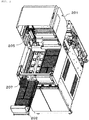
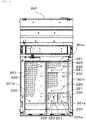
- Fig. 2 illustrates a perspective view of the specimen storing unit
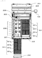
- Fig. 3 illustrates a top view of the specimen loading unit of Fig. 2 .
- the specimen storing unit since configurations of the specimen storing unit and the specimen loading unit are often similar to each other, the specimen storing unit will be described as an example of the embodiments. Meanwhile, the specimen loading unit can be also formed based upon the same configuration.
- a specimen storing unit 201 includes a specimen tray installation part 202 for installing a specimen tray 301 on which a plurality of specimen containers 207 can be installed, an identification information reader part 206 for reading identification information of the specimen tray 301, a specimen-conveying conveyor 203 for conveying the specimen container in the specimen inspection automation system, a bar-code reader 204 for reading the identification information stuck to the specimen container 207, and a specimen container transferring mechanism 205 for transferring the specimen container 207 between the specimen-conveying conveyor 203 and the specimen tray 301.
- the specimen tray installation part 202 is a drawer type, thereby considering usability when the specimen tray is installed.
- the specimen tray installation part 202 illustrates two examples.
- the specimen tray installation part 202 is not limited thereto and can be formed by an arbitrary number.
- the specimen tray installation part 202 is not required to be the drawer type.
- a plurality of the specimen trays can be installed in the specimen tray installation part 202. Additionally, the plurality of specimen trays may have a different size.
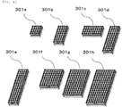
- a plurality of types of sizes are prepared for the specimen tray 303. That is, a specimen tray having a different number of the specimen container installation parts for holding the specimen container or having a different arrangement thereof is used as the specimen tray installed in the specimen tray installation part 202.
- the storage number of the tray in a lateral direction of the minimum storage number is referred to as m
- the storage number of the tray in a vertical direction thereof is referred to as n (m and n are respectively positive integer values).
- trays are formed as K ⁇ m rows and L ⁇ n columns (K and L are respectively positive integer values) .
- the specimen trays are illustrated as 8 types from 301a to 201h as one example.
- the number of rows and columns is an integer multiple of m and n, it is possible not only to increase the installation number of the specimen containers, but also to freely divide the type of the specimen trays.
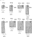
- An identification information tag 209 is attached to each specimen tray at a predetermined position.
- a size of the own specimen tray and a specific identification number of each specimen tray are registered in advance.
- the specific identification number of the specimen tray 301 may be further clearly described in a body of the specimen tray 301.
- the identification information tag 209 will be described later with reference to Figs. 5 and 6 .
- An operator handling the system registers use of the specimen tray 301 expected to be used in the specimen storing unit 201 and a specimen tray to be used for the above-mentioned use in the controller 106 in advance.
- the operator can select and register the specimen tray having a desirable size depending on the use of the specimen tray 301.
- a specimen tray to be used for preservation is registered as the specimen tray 301h for holding 200 specimen containers that is capable of installing 200 specimen containers.
- a tray for outsourcing inspection is registered as the specimen tray 301a for holding 25 specimen containers, and the like.
- the operator arranges the specimen tray 301 registered in the specimen tray installation part 202, which is drawn out, at a desired position.
- the identification information tag 209 of the specimen tray 301 is overlapped with the identification information reader part 206, such that the identification information tag 209 thereof can be read.
- a plurality of the identification information reader parts 206 are provided directly under the specimen tray installation part 202 (a position directly under the specimen tray installation part 202 when the drawer is closed).
- the identification information reader part 206 reads information for identifying a type of the specimen tray 301 from the identification information tag of the specimen tray 301 installed in the specimen tray installation part 202.
- the controller 106 recognizes an arrangement position of the specimen tray 301 and a size thereof based upon the information read by the identification information reader part 206, after which an arrangement state of the specimen tray arranged in the specimen storing unit 201 is stored in a storage part (not illustrated) connected to the controller 106.
- the storage part is a memory of a computer or a hard disk thereof.
- the information on the arrangement state of the specimen tray 301 is updated by opening and closing the drawer of the specimen tray installation part 202 and by exchanging the specimen tray 301. An update timing can be set by the controller 106.
- the specimen container loaded from the specimen loading unit is performed with various kinds of processing in the specimen inspection automation system and then arrives at a specimen transferring position 208 via the specimen-conveying conveyor 203 in the system.
- the identification information stuck to the specimen container is read by the bar-code reader 204.
- the controller 106 is inquired about the aforementioned information.
- the controller 106 discriminates the specimen tray corresponding to the processing corresponding to the specimen and instructs the specimen tray of a storage destination.
- the specimen container is transferred to the specimen tray instructed from the controller 106 by the specimen container transferring mechanism 205. For example, when there is an instruction for preservation, the tray is transferred to a position where the tray 301h for holding 200 specimen containers registered in advance is arranged.
- the controller 106 stores the specific number of the specimen tray by which the specimen container 207 is transferred and the position thereof, so that the specific number and the position can be searched by the controller 106. Therefore, when re-inspection is required to be performed in the automatic analyzer 101 or 102, the corresponding specimen container 207 can be fetched again in the specimen inspection automation system according to the instruction from the controller 106. In this case, first, the position of the specimen tray 301 in which the specimen container required to be re-inspected is installed is specified by the controller 106. The controller 106 instructs the specimen container transferring mechanism 205 to collect the specimen container from the corresponding position.
- the specimen container transferring mechanism 205 collects the specimen container according to the instruction and transfers the specimen container to the specimen transferring position 208 on the specimen-conveying conveyor 203.
- the bar-code reader 204 reads the identification information of the transferred specimen container.
- the controller 106 is inquired about the following processing with respect to the corresponding specimen based upon the information read by the bar-code reader 204, and the corresponding specimen is conveyed again into the system according to the instruction of the controller 106.
- Fig. 5 illustrates a top view of the specimen tray of Fig. 4 .
- the identification information tag 209 and a positioning part (recessed part) 210 are provided on bottom parts of the respective specimen trays.
- the identification information tag 209 and the positioning part (recessed part) 210 are provided at predetermined positions in the respective specimen trays. More specifically, for example, each specimen tray is provided at a position becoming a predetermined distance from an end surface of each specimen tray (for example, an upper surface and a right-side surface).
- the identification information tag 209 can read information in an RFID tag when entering in a predetermined distance range from the identification information reader part 206.
- the identification information tag 209 is the RFID tag
- the identification information reader part 206 is an RFID reader.
- a plurality of the identification information reader parts 206 for reading the identification information are regularly arranged at positions where the identification information tags 209 of the specimen trays 301a to 301h can be read in the specimen storing unit. More specifically, when the specimen tray installation part is the drawer type, the identification information reader is arranged in such a manner that the identification information tag of the specimen tray that is normally arranged is positioned within a predetermined distance range when the drawer is closed.
- sixteen identification information reader parts 206 are arranged and can be increased or decreased depending on a type of the usable specimen tray.
- a position where the specimen tray is arranged can be determined based upon a combination of successful or unsuccessful reading of the identification information in the respective plurality of identification information readers.
- the specimen trays can be arranged in a free combination even though the types of the specimen trays are increased by including a mechanical interface according to the combination of the RFID tag and the RFID reader.
- numbers are determined from No. 1 to identify the respective specimen container installation parts in the specimen container installation parts of the respective specimen trays, and numbers corresponding to the maximum installation number of the specimen containers are allocated thereto.
- the specimen tray 301f is used as an example.
- the specimen container installation part of the specimen tray is an integer multiple in vertical and horizontal directions of the trays having the minimum storage number
- the specimen container installation part can be freely formed as n rows ⁇ m columns.
- a distance (pitch) between the specimen container installation parts and a distance from an end surface of the specimen container are defined.
- the specimen container installation part is arranged to accomplish a relationship as described below. p 1 > d 1 + d 2 and p 2 > d 3 + d 4 here,
- the positioning part (the recessed part) 210 at a time of the installation is provided on a bottom surface of the specimen tray 301 and provided at a position which becomes a reference of the specimen tray 301.
- a positioning part (a projected part) 211 which is engaged with the positioning part (the recessed part) 210 is regularly arranged in the specimen tray installation part 202 of the specimen storing unit 201. Positioning with respect to a regular position can be performed in the fitting of the recessed part and the projected part.
- a position where the specimen tray 301 is installed can be limited to a position where the positioning part (the recessed part) 210 and the positioning part (the projected part) 211 are engaged with each other. Then, when the positioning part (the recessed part) 210 and the positioning part (the projected part) 211 are installed at a fitting position, the identification information reader part 206 is arranged in such a manner that the identification information tag 209 is arranged in a range where the identification information tag 209 is readable by the identification information reader part 206.
- the specimen tray 301 When the specimen tray 301 is installed at a wrong position, the above-mentioned two positioning parts cannot be fitted to each other, such that the specimen tray 301 floats up, and thus the drawer of the specimen tray installation part 202 becomes a structure in which the drawer thereof cannot be returned.
- the specimen tray may be provided with the projected part, and the specimen storing unit may be provided with the recessed part.
- the specimen storing unit 201 when installation failure of the specimen tray 301 or incorrect installation thereof (installation direction error) occurs, there exist a risk of specimen loss caused by installation failure of the specimen container 207 and a risk of mismatching of installation position information. Therefore, it is required to clearly install the specimen tray. According to the exemplary embodiment, since the specimen storing unit 201 cannot recognize the incorrectly installed specimen tray 301, the risk of the specimen loss caused by the installation failure of the specimen container 207, the risk of the mismatching of the installation position information, and the like can be prevented in advance.
- Fig. 8 illustrates an example of an actual arrangement of the specimen trays 301a to 301h combined with the specimen storing unit 201.
- Fig. 8 is a diagram illustrating a top surface of the specimen storing unit 201. Here, a part of the specimen tray is omitted in the diagram of the specimen container, and a state of a bottom surface of the specimen tray is illustrated.
- positioning of the positioning part (the recessed part) and the positioning part (the projected part) is clearly performed at a fitting position 220. Further, the identification information reader part and the identification information tag are overlapped with each other at a specified position 221, such that the identification information can be read.
- a specimen tray of the related art has adopted a specimen tray which is suitable for each specimen inspection automation system in consideration of a size of the specimen storing unit or a size of the specimen loading unit, a maximum installable number of the specimen containers as a unit, and the like.
- a type of the specimen tray which is usable in the specimen tray installation part is fixed.
- a plurality of types of the specimen trays can be flexibly used without remodeling hardware, thereby having an effect of selecting a tray in consideration of the use of a user.
- the specimen containers sorted according to a scale of a facility, specialty, a specimen type, and the like vary depending on operation.
- a choice option of the specimen tray is expanded depending on the operation, thereby improving convenience.
- the specimen tray of the exemplary embodiment When the specimen tray of the exemplary embodiment is used in the specimen storing unit, a specimen tray which can install a large quantity is desirably required for preservation, whereas a specimen tray having a small installable number is sufficient for analysis by hand in which the number of processes is small. Accordingly, since the specimen trays set in a plurality of storage destinations (sorting destinations) can be efficiently installed, the choice option of the specimen tray corresponding to the operation of the user is expanded, thereby improving the convenience.
- the present invention is not limited to the exemplary embodiments described above, but on the contrary, is intended to cover various modifications. While the exemplary embodiments are described in detail to describe the present invention in an easily understood manner, it is understood that the invention is not limited to the disclosed configurations. Further, a part of the configuration of one exemplary embodiment can be replaced with a configuration of another exemplary embodiment, and the configuration of another exemplary embodiment can be added to the configuration of one exemplary embodiment. Further, it is possible to add, delete, and replace another configuration with respect to a part of the configuration of each exemplary embodiment.
Landscapes
- Chemical & Material Sciences (AREA)
- Physics & Mathematics (AREA)
- Health & Medical Sciences (AREA)
- Life Sciences & Earth Sciences (AREA)
- Analytical Chemistry (AREA)
- Biochemistry (AREA)
- General Health & Medical Sciences (AREA)
- General Physics & Mathematics (AREA)
- Immunology (AREA)
- Pathology (AREA)
- Chemical Kinetics & Catalysis (AREA)
- Automatic Analysis And Handling Materials Therefor (AREA)
Applications Claiming Priority (2)
| Application Number | Priority Date | Filing Date | Title |
|---|---|---|---|
| JP2016035034 | 2016-02-26 | ||
| PCT/JP2017/000916 WO2017145556A1 (ja) | 2016-02-26 | 2017-01-13 | 検体容器投入または収納ユニット |
Publications (3)
| Publication Number | Publication Date |
|---|---|
| EP3422016A1 true EP3422016A1 (de) | 2019-01-02 |
| EP3422016A4 EP3422016A4 (de) | 2019-09-04 |
| EP3422016B1 EP3422016B1 (de) | 2021-10-27 |
Family
ID=59685183
Family Applications (1)
| Application Number | Title | Priority Date | Filing Date |
|---|---|---|---|
| EP17755998.6A Active EP3422016B1 (de) | 2016-02-26 | 2017-01-13 | Einheit zum bestücken/lagern von probenbehältern |
Country Status (5)
| Country | Link |
|---|---|
| US (1) | US20190041412A1 (de) |
| EP (1) | EP3422016B1 (de) |
| JP (1) | JPWO2017145556A1 (de) |
| CN (1) | CN108700605A (de) |
| WO (1) | WO2017145556A1 (de) |
Cited By (2)
| Publication number | Priority date | Publication date | Assignee | Title |
|---|---|---|---|---|
| WO2020239811A1 (en) * | 2019-05-28 | 2020-12-03 | Roche Diagnostics Gmbh | Automatic analyzer |
| US12313643B2 (en) | 2019-05-28 | 2025-05-27 | Roche Diagnostics Operations, Inc. | Reagent drawer and associated detector mounted to a slider capable of extending from an automatic analyzer housing |
Families Citing this family (8)
| Publication number | Priority date | Publication date | Assignee | Title |
|---|---|---|---|---|
| CN108732135A (zh) * | 2017-11-20 | 2018-11-02 | 重庆中元汇吉生物技术有限公司 | 一种血液细胞及蛋白分析装置 |
| JP7163963B2 (ja) * | 2018-08-30 | 2022-11-01 | 株式会社島津製作所 | 試料プレート供給制御装置、試料プレート供給制御システム、試料プレート供給制御方法および試料プレート供給制御プログラム |
| JP7274580B2 (ja) * | 2019-07-22 | 2023-05-16 | 株式会社日立ハイテク | 検体検査自動化システム、及び検体検査方法 |
| JP7431534B2 (ja) | 2019-08-23 | 2024-02-15 | シスメックス株式会社 | 試料処理装置、ホルダ、および試料測定システム |
| CN115088403B (zh) * | 2020-03-10 | 2023-08-01 | 株式会社富士 | 元件仓库 |
| CN111637675B (zh) * | 2020-06-01 | 2021-06-04 | 迪瑞医疗科技股份有限公司 | 一种样本低温自动储存设备及方法 |
| LU103025B1 (en) * | 2022-09-27 | 2024-03-28 | Stratec Se | Drawer for bulk liquid supply |
| CN116429530B (zh) * | 2023-03-28 | 2026-03-06 | 桂林优利特医疗电子有限公司 | 一种样本后处理系统及控制方法 |
Family Cites Families (14)
| Publication number | Priority date | Publication date | Assignee | Title |
|---|---|---|---|---|
| US6838051B2 (en) * | 1999-05-03 | 2005-01-04 | Ljl Biosystems, Inc. | Integrated sample-processing system |
| AU1103101A (en) * | 1999-10-26 | 2001-05-08 | Genometrix Genomics Incorporated | Method and apparatus for selectively retrieving biological samples for processing |
| US7352889B2 (en) * | 2000-10-30 | 2008-04-01 | Ganz Brian L | Automated storage and retrieval device and method |
| US20030069699A1 (en) * | 2001-05-16 | 2003-04-10 | Sean Ekins | Device for drug-drug interaction testing sample preparation |
| JP4130816B2 (ja) * | 2004-07-16 | 2008-08-06 | アロカ株式会社 | 認識装置および分注装置 |
| FR2888328B1 (fr) * | 2005-07-08 | 2013-09-20 | Horiba Abx Sas | Procede automatise de preparation d'analyse d'echantillons de sang total et dispositif automatise pour sa mise en oeuvre |
| JP2007304874A (ja) * | 2006-05-11 | 2007-11-22 | Aruze Corp | 無線icタグの位置特定システム、並びに位置特定装置 |
| JP5208868B2 (ja) * | 2008-10-31 | 2013-06-12 | シスメックス株式会社 | 検体処理装置 |
| US9753048B2 (en) * | 2010-05-24 | 2017-09-05 | Hitachi High-Technologies Corporation | Sample test automation system |
| JP5425728B2 (ja) * | 2010-07-15 | 2014-02-26 | 株式会社日立ハイテクノロジーズ | 検体処理システム |
| EP2455762A1 (de) * | 2010-11-17 | 2012-05-23 | M-u-t AG Messgeräte für Medizin- und Umwelttechnik | Laborautomatisierungssystem |
| US9857389B2 (en) * | 2012-09-12 | 2018-01-02 | Hitachi High-Technologies Corporation | Specimen storage apparatus, specimen processing system, and controlling method thereof |
| US9336422B2 (en) * | 2013-02-22 | 2016-05-10 | Beckman Coulter, Inc. | Rack orientation detection with multiple tags |
| JP6189697B2 (ja) * | 2013-09-30 | 2017-08-30 | シスメックス株式会社 | 検体移し替え装置及び検体処理システム |
-
2017
- 2017-01-13 WO PCT/JP2017/000916 patent/WO2017145556A1/ja not_active Ceased
- 2017-01-13 JP JP2018501034A patent/JPWO2017145556A1/ja active Pending
- 2017-01-13 EP EP17755998.6A patent/EP3422016B1/de active Active
- 2017-01-13 US US16/075,215 patent/US20190041412A1/en not_active Abandoned
- 2017-01-13 CN CN201780013146.1A patent/CN108700605A/zh active Pending
Cited By (4)
| Publication number | Priority date | Publication date | Assignee | Title |
|---|---|---|---|---|
| WO2020239811A1 (en) * | 2019-05-28 | 2020-12-03 | Roche Diagnostics Gmbh | Automatic analyzer |
| EP3977139A1 (de) * | 2019-05-28 | 2022-04-06 | Roche Diagnostics GmbH | Automatischer analysator |
| US12313643B2 (en) | 2019-05-28 | 2025-05-27 | Roche Diagnostics Operations, Inc. | Reagent drawer and associated detector mounted to a slider capable of extending from an automatic analyzer housing |
| EP3977139B1 (de) * | 2019-05-28 | 2025-07-16 | Roche Diagnostics GmbH | Automatischer analysator |
Also Published As
| Publication number | Publication date |
|---|---|
| JPWO2017145556A1 (ja) | 2018-12-13 |
| EP3422016A4 (de) | 2019-09-04 |
| EP3422016B1 (de) | 2021-10-27 |
| WO2017145556A1 (ja) | 2017-08-31 |
| US20190041412A1 (en) | 2019-02-07 |
| CN108700605A (zh) | 2018-10-23 |
Similar Documents
| Publication | Publication Date | Title |
|---|---|---|
| EP3422016B1 (de) | Einheit zum bestücken/lagern von probenbehältern | |
| JP6743204B2 (ja) | 容器ホルダの保管および供給 | |
| US10150620B2 (en) | Sample transfer device and sample processing system | |
| US9952239B2 (en) | Sample inspection automation system and sample transfer method | |
| US6588625B2 (en) | Sample handling system | |
| ES2333697T3 (es) | Metodo para la gestion de sistemas de celula de trabajo basado en un sistema de gestion de la automatizacion. | |
| JP6741562B2 (ja) | 実験室装置、実験室装置の操作方法、およびコンピュータプログラム製品 | |
| EP3626652B1 (de) | Verbrauchbares verwaltungssystem für laboratorien | |
| US9823261B2 (en) | Multi-well wedge-shaped reagent container with auto-open capability | |
| CN104024864A (zh) | 检体转运装置和系统 | |
| US8822224B2 (en) | Method for automatic testing of anatomical laboratory specimens | |
| WO2013170204A1 (en) | Augmented reality for workflow assistance | |
| EP3922996B1 (de) | Automatische analysevorrichtung | |
| US11467173B2 (en) | Sample container loading or storing unit and sample test automation system provided with same | |
| EP3872498A1 (de) | Automatische probenentnahmevorrichtung, automatisches analysegerät, probenentnahmeverfahren und automatisches inspektionsverfahren | |
| EP3872497A1 (de) | Automatische probenahmevorrichtung, automatisches analysegerät, probenahmeverfahren und automatisches inspektionsverfahren | |
| EP4644910A1 (de) | Vorrichtung zum sortieren von probenbehältern |
Legal Events
| Date | Code | Title | Description |
|---|---|---|---|
| STAA | Information on the status of an ep patent application or granted ep patent |
Free format text: STATUS: THE INTERNATIONAL PUBLICATION HAS BEEN MADE |
|
| PUAI | Public reference made under article 153(3) epc to a published international application that has entered the european phase |
Free format text: ORIGINAL CODE: 0009012 |
|
| STAA | Information on the status of an ep patent application or granted ep patent |
Free format text: STATUS: REQUEST FOR EXAMINATION WAS MADE |
|
| 17P | Request for examination filed |
Effective date: 20180821 |
|
| AK | Designated contracting states |
Kind code of ref document: A1 Designated state(s): AL AT BE BG CH CY CZ DE DK EE ES FI FR GB GR HR HU IE IS IT LI LT LU LV MC MK MT NL NO PL PT RO RS SE SI SK SM TR |
|
| AX | Request for extension of the european patent |
Extension state: BA ME |
|
| DAV | Request for validation of the european patent (deleted) | ||
| DAX | Request for extension of the european patent (deleted) | ||
| A4 | Supplementary search report drawn up and despatched |
Effective date: 20190802 |
|
| RIC1 | Information provided on ipc code assigned before grant |
Ipc: G01N 35/02 20060101ALI20190729BHEP Ipc: G01N 35/04 20060101AFI20190729BHEP |
|
| STAA | Information on the status of an ep patent application or granted ep patent |
Free format text: STATUS: EXAMINATION IS IN PROGRESS |
|
| 17Q | First examination report despatched |
Effective date: 20200519 |
|
| RAP1 | Party data changed (applicant data changed or rights of an application transferred) |
Owner name: HITACHI HIGH-TECH CORPORATION |
|
| REG | Reference to a national code |
Ref country code: DE Ref legal event code: R079 Ref document number: 602017048295 Country of ref document: DE Free format text: PREVIOUS MAIN CLASS: G01N0035040000 Ipc: G01N0035000000 |
|
| GRAP | Despatch of communication of intention to grant a patent |
Free format text: ORIGINAL CODE: EPIDOSNIGR1 |
|
| STAA | Information on the status of an ep patent application or granted ep patent |
Free format text: STATUS: GRANT OF PATENT IS INTENDED |
|
| RIC1 | Information provided on ipc code assigned before grant |
Ipc: G01N 35/02 20060101ALI20210624BHEP Ipc: G01N 35/04 20060101ALI20210624BHEP Ipc: G01N 35/00 20060101AFI20210624BHEP |
|
| INTG | Intention to grant announced |
Effective date: 20210713 |
|
| GRAS | Grant fee paid |
Free format text: ORIGINAL CODE: EPIDOSNIGR3 |
|
| GRAA | (expected) grant |
Free format text: ORIGINAL CODE: 0009210 |
|
| STAA | Information on the status of an ep patent application or granted ep patent |
Free format text: STATUS: THE PATENT HAS BEEN GRANTED |
|
| AK | Designated contracting states |
Kind code of ref document: B1 Designated state(s): AL AT BE BG CH CY CZ DE DK EE ES FI FR GB GR HR HU IE IS IT LI LT LU LV MC MK MT NL NO PL PT RO RS SE SI SK SM TR |
|
| REG | Reference to a national code |
Ref country code: GB Ref legal event code: FG4D |
|
| RIN1 | Information on inventor provided before grant (corrected) |
Inventor name: ENDO MASASHI Inventor name: TSUJIMURA NAOTO |
|
| REG | Reference to a national code |
Ref country code: CH Ref legal event code: EP |
|
| REG | Reference to a national code |
Ref country code: DE Ref legal event code: R096 Ref document number: 602017048295 Country of ref document: DE |
|
| REG | Reference to a national code |
Ref country code: AT Ref legal event code: REF Ref document number: 1442246 Country of ref document: AT Kind code of ref document: T Effective date: 20211115 |
|
| REG | Reference to a national code |
Ref country code: IE Ref legal event code: FG4D |
|
| REG | Reference to a national code |
Ref country code: LT Ref legal event code: MG9D |
|
| REG | Reference to a national code |
Ref country code: NL Ref legal event code: MP Effective date: 20211027 |
|
| REG | Reference to a national code |
Ref country code: AT Ref legal event code: MK05 Ref document number: 1442246 Country of ref document: AT Kind code of ref document: T Effective date: 20211027 |
|
| PG25 | Lapsed in a contracting state [announced via postgrant information from national office to epo] |
Ref country code: RS Free format text: LAPSE BECAUSE OF FAILURE TO SUBMIT A TRANSLATION OF THE DESCRIPTION OR TO PAY THE FEE WITHIN THE PRESCRIBED TIME-LIMIT Effective date: 20211027 Ref country code: LT Free format text: LAPSE BECAUSE OF FAILURE TO SUBMIT A TRANSLATION OF THE DESCRIPTION OR TO PAY THE FEE WITHIN THE PRESCRIBED TIME-LIMIT Effective date: 20211027 Ref country code: FI Free format text: LAPSE BECAUSE OF FAILURE TO SUBMIT A TRANSLATION OF THE DESCRIPTION OR TO PAY THE FEE WITHIN THE PRESCRIBED TIME-LIMIT Effective date: 20211027 Ref country code: BG Free format text: LAPSE BECAUSE OF FAILURE TO SUBMIT A TRANSLATION OF THE DESCRIPTION OR TO PAY THE FEE WITHIN THE PRESCRIBED TIME-LIMIT Effective date: 20220127 Ref country code: AT Free format text: LAPSE BECAUSE OF FAILURE TO SUBMIT A TRANSLATION OF THE DESCRIPTION OR TO PAY THE FEE WITHIN THE PRESCRIBED TIME-LIMIT Effective date: 20211027 |
|
| PG25 | Lapsed in a contracting state [announced via postgrant information from national office to epo] |
Ref country code: IS Free format text: LAPSE BECAUSE OF FAILURE TO SUBMIT A TRANSLATION OF THE DESCRIPTION OR TO PAY THE FEE WITHIN THE PRESCRIBED TIME-LIMIT Effective date: 20220227 Ref country code: SE Free format text: LAPSE BECAUSE OF FAILURE TO SUBMIT A TRANSLATION OF THE DESCRIPTION OR TO PAY THE FEE WITHIN THE PRESCRIBED TIME-LIMIT Effective date: 20211027 Ref country code: PT Free format text: LAPSE BECAUSE OF FAILURE TO SUBMIT A TRANSLATION OF THE DESCRIPTION OR TO PAY THE FEE WITHIN THE PRESCRIBED TIME-LIMIT Effective date: 20220228 Ref country code: PL Free format text: LAPSE BECAUSE OF FAILURE TO SUBMIT A TRANSLATION OF THE DESCRIPTION OR TO PAY THE FEE WITHIN THE PRESCRIBED TIME-LIMIT Effective date: 20211027 Ref country code: NO Free format text: LAPSE BECAUSE OF FAILURE TO SUBMIT A TRANSLATION OF THE DESCRIPTION OR TO PAY THE FEE WITHIN THE PRESCRIBED TIME-LIMIT Effective date: 20220127 Ref country code: NL Free format text: LAPSE BECAUSE OF FAILURE TO SUBMIT A TRANSLATION OF THE DESCRIPTION OR TO PAY THE FEE WITHIN THE PRESCRIBED TIME-LIMIT Effective date: 20211027 Ref country code: LV Free format text: LAPSE BECAUSE OF FAILURE TO SUBMIT A TRANSLATION OF THE DESCRIPTION OR TO PAY THE FEE WITHIN THE PRESCRIBED TIME-LIMIT Effective date: 20211027 Ref country code: HR Free format text: LAPSE BECAUSE OF FAILURE TO SUBMIT A TRANSLATION OF THE DESCRIPTION OR TO PAY THE FEE WITHIN THE PRESCRIBED TIME-LIMIT Effective date: 20211027 Ref country code: GR Free format text: LAPSE BECAUSE OF FAILURE TO SUBMIT A TRANSLATION OF THE DESCRIPTION OR TO PAY THE FEE WITHIN THE PRESCRIBED TIME-LIMIT Effective date: 20220128 Ref country code: ES Free format text: LAPSE BECAUSE OF FAILURE TO SUBMIT A TRANSLATION OF THE DESCRIPTION OR TO PAY THE FEE WITHIN THE PRESCRIBED TIME-LIMIT Effective date: 20211027 |
|
| REG | Reference to a national code |
Ref country code: DE Ref legal event code: R097 Ref document number: 602017048295 Country of ref document: DE |
|
| PG25 | Lapsed in a contracting state [announced via postgrant information from national office to epo] |
Ref country code: SM Free format text: LAPSE BECAUSE OF FAILURE TO SUBMIT A TRANSLATION OF THE DESCRIPTION OR TO PAY THE FEE WITHIN THE PRESCRIBED TIME-LIMIT Effective date: 20211027 Ref country code: SK Free format text: LAPSE BECAUSE OF FAILURE TO SUBMIT A TRANSLATION OF THE DESCRIPTION OR TO PAY THE FEE WITHIN THE PRESCRIBED TIME-LIMIT Effective date: 20211027 Ref country code: RO Free format text: LAPSE BECAUSE OF FAILURE TO SUBMIT A TRANSLATION OF THE DESCRIPTION OR TO PAY THE FEE WITHIN THE PRESCRIBED TIME-LIMIT Effective date: 20211027 Ref country code: EE Free format text: LAPSE BECAUSE OF FAILURE TO SUBMIT A TRANSLATION OF THE DESCRIPTION OR TO PAY THE FEE WITHIN THE PRESCRIBED TIME-LIMIT Effective date: 20211027 Ref country code: DK Free format text: LAPSE BECAUSE OF FAILURE TO SUBMIT A TRANSLATION OF THE DESCRIPTION OR TO PAY THE FEE WITHIN THE PRESCRIBED TIME-LIMIT Effective date: 20211027 Ref country code: CZ Free format text: LAPSE BECAUSE OF FAILURE TO SUBMIT A TRANSLATION OF THE DESCRIPTION OR TO PAY THE FEE WITHIN THE PRESCRIBED TIME-LIMIT Effective date: 20211027 |
|
| PG25 | Lapsed in a contracting state [announced via postgrant information from national office to epo] |
Ref country code: MC Free format text: LAPSE BECAUSE OF FAILURE TO SUBMIT A TRANSLATION OF THE DESCRIPTION OR TO PAY THE FEE WITHIN THE PRESCRIBED TIME-LIMIT Effective date: 20211027 |
|
| REG | Reference to a national code |
Ref country code: CH Ref legal event code: PL |
|
| PLBE | No opposition filed within time limit |
Free format text: ORIGINAL CODE: 0009261 |
|
| STAA | Information on the status of an ep patent application or granted ep patent |
Free format text: STATUS: NO OPPOSITION FILED WITHIN TIME LIMIT |
|
| GBPC | Gb: european patent ceased through non-payment of renewal fee |
Effective date: 20220127 |
|
| REG | Reference to a national code |
Ref country code: BE Ref legal event code: MM Effective date: 20220131 |
|
| 26N | No opposition filed |
Effective date: 20220728 |
|
| PG25 | Lapsed in a contracting state [announced via postgrant information from national office to epo] |
Ref country code: LU Free format text: LAPSE BECAUSE OF NON-PAYMENT OF DUE FEES Effective date: 20220113 Ref country code: GB Free format text: LAPSE BECAUSE OF NON-PAYMENT OF DUE FEES Effective date: 20220127 Ref country code: AL Free format text: LAPSE BECAUSE OF FAILURE TO SUBMIT A TRANSLATION OF THE DESCRIPTION OR TO PAY THE FEE WITHIN THE PRESCRIBED TIME-LIMIT Effective date: 20211027 |
|
| PG25 | Lapsed in a contracting state [announced via postgrant information from national office to epo] |
Ref country code: SI Free format text: LAPSE BECAUSE OF FAILURE TO SUBMIT A TRANSLATION OF THE DESCRIPTION OR TO PAY THE FEE WITHIN THE PRESCRIBED TIME-LIMIT Effective date: 20211027 Ref country code: BE Free format text: LAPSE BECAUSE OF NON-PAYMENT OF DUE FEES Effective date: 20220131 |
|
| PG25 | Lapsed in a contracting state [announced via postgrant information from national office to epo] |
Ref country code: LI Free format text: LAPSE BECAUSE OF NON-PAYMENT OF DUE FEES Effective date: 20220131 Ref country code: CH Free format text: LAPSE BECAUSE OF NON-PAYMENT OF DUE FEES Effective date: 20220131 |
|
| PG25 | Lapsed in a contracting state [announced via postgrant information from national office to epo] |
Ref country code: IE Free format text: LAPSE BECAUSE OF NON-PAYMENT OF DUE FEES Effective date: 20220113 |
|
| PG25 | Lapsed in a contracting state [announced via postgrant information from national office to epo] |
Ref country code: IT Free format text: LAPSE BECAUSE OF FAILURE TO SUBMIT A TRANSLATION OF THE DESCRIPTION OR TO PAY THE FEE WITHIN THE PRESCRIBED TIME-LIMIT Effective date: 20211027 |
|
| PG25 | Lapsed in a contracting state [announced via postgrant information from national office to epo] |
Ref country code: HU Free format text: LAPSE BECAUSE OF FAILURE TO SUBMIT A TRANSLATION OF THE DESCRIPTION OR TO PAY THE FEE WITHIN THE PRESCRIBED TIME-LIMIT; INVALID AB INITIO Effective date: 20170113 |
|
| PG25 | Lapsed in a contracting state [announced via postgrant information from national office to epo] |
Ref country code: MK Free format text: LAPSE BECAUSE OF FAILURE TO SUBMIT A TRANSLATION OF THE DESCRIPTION OR TO PAY THE FEE WITHIN THE PRESCRIBED TIME-LIMIT Effective date: 20211027 Ref country code: CY Free format text: LAPSE BECAUSE OF FAILURE TO SUBMIT A TRANSLATION OF THE DESCRIPTION OR TO PAY THE FEE WITHIN THE PRESCRIBED TIME-LIMIT Effective date: 20211027 |
|
| PG25 | Lapsed in a contracting state [announced via postgrant information from national office to epo] |
Ref country code: TR Free format text: LAPSE BECAUSE OF FAILURE TO SUBMIT A TRANSLATION OF THE DESCRIPTION OR TO PAY THE FEE WITHIN THE PRESCRIBED TIME-LIMIT Effective date: 20211027 |
|
| PG25 | Lapsed in a contracting state [announced via postgrant information from national office to epo] |
Ref country code: MT Free format text: LAPSE BECAUSE OF FAILURE TO SUBMIT A TRANSLATION OF THE DESCRIPTION OR TO PAY THE FEE WITHIN THE PRESCRIBED TIME-LIMIT Effective date: 20211027 |
|
| PGFP | Annual fee paid to national office [announced via postgrant information from national office to epo] |
Ref country code: FR Payment date: 20251217 Year of fee payment: 10 |
|
| PGFP | Annual fee paid to national office [announced via postgrant information from national office to epo] |
Ref country code: DE Payment date: 20251217 Year of fee payment: 10 |