EP3420907A2 - Imagerie à distance variable - Google Patents
Imagerie à distance variable Download PDFInfo
- Publication number
- EP3420907A2 EP3420907A2 EP18179522.0A EP18179522A EP3420907A2 EP 3420907 A2 EP3420907 A2 EP 3420907A2 EP 18179522 A EP18179522 A EP 18179522A EP 3420907 A2 EP3420907 A2 EP 3420907A2
- Authority
- EP
- European Patent Office
- Prior art keywords
- imaging
- detector
- source
- ray
- patient
- Prior art date
- Legal status (The legal status is an assumption and is not a legal conclusion. Google has not performed a legal analysis and makes no representation as to the accuracy of the status listed.)
- Withdrawn
Links
- 238000003384 imaging method Methods 0.000 title claims abstract description 166
- 238000000034 method Methods 0.000 claims abstract description 73
- 230000005855 radiation Effects 0.000 claims abstract description 18
- 230000002238 attenuated effect Effects 0.000 claims abstract description 7
- 238000000326 densiometry Methods 0.000 claims description 16
- 238000002059 diagnostic imaging Methods 0.000 claims description 8
- 238000009547 dual-energy X-ray absorptiometry Methods 0.000 claims description 7
- 230000004907 flux Effects 0.000 claims description 6
- 238000010521 absorption reaction Methods 0.000 claims description 5
- 230000009467 reduction Effects 0.000 claims description 5
- 210000000988 bone and bone Anatomy 0.000 description 19
- 238000010586 diagram Methods 0.000 description 8
- 210000001519 tissue Anatomy 0.000 description 6
- 230000009977 dual effect Effects 0.000 description 5
- MARUHZGHZWCEQU-UHFFFAOYSA-N 5-phenyl-2h-tetrazole Chemical compound C1=CC=CC=C1C1=NNN=N1 MARUHZGHZWCEQU-UHFFFAOYSA-N 0.000 description 4
- 238000007408 cone-beam computed tomography Methods 0.000 description 4
- 238000005259 measurement Methods 0.000 description 4
- 239000004065 semiconductor Substances 0.000 description 4
- 210000003484 anatomy Anatomy 0.000 description 3
- 230000037182 bone density Effects 0.000 description 3
- 230000008859 change Effects 0.000 description 3
- 238000012937 correction Methods 0.000 description 3
- 229910052500 inorganic mineral Inorganic materials 0.000 description 3
- 239000000463 material Substances 0.000 description 3
- 239000011707 mineral Substances 0.000 description 3
- 238000012545 processing Methods 0.000 description 3
- 238000002601 radiography Methods 0.000 description 3
- 210000004872 soft tissue Anatomy 0.000 description 3
- 208000001132 Osteoporosis Diseases 0.000 description 2
- 230000008901 benefit Effects 0.000 description 2
- 230000001419 dependent effect Effects 0.000 description 2
- 238000003745 diagnosis Methods 0.000 description 2
- 238000011156 evaluation Methods 0.000 description 2
- 230000008569 process Effects 0.000 description 2
- 208000020084 Bone disease Diseases 0.000 description 1
- 238000002583 angiography Methods 0.000 description 1
- 238000013459 approach Methods 0.000 description 1
- 210000000481 breast Anatomy 0.000 description 1
- 239000003795 chemical substances by application Substances 0.000 description 1
- 238000013170 computed tomography imaging Methods 0.000 description 1
- 230000003247 decreasing effect Effects 0.000 description 1
- 230000007850 degeneration Effects 0.000 description 1
- 230000000694 effects Effects 0.000 description 1
- 230000006870 function Effects 0.000 description 1
- 238000010191 image analysis Methods 0.000 description 1
- 238000001727 in vivo Methods 0.000 description 1
- 238000011835 investigation Methods 0.000 description 1
- 210000004185 liver Anatomy 0.000 description 1
- 238000009607 mammography Methods 0.000 description 1
- 238000012986 modification Methods 0.000 description 1
- 230000004048 modification Effects 0.000 description 1
- 210000000056 organ Anatomy 0.000 description 1
- 210000004789 organ system Anatomy 0.000 description 1
- 238000000053 physical method Methods 0.000 description 1
- 238000007781 pre-processing Methods 0.000 description 1
- 230000000750 progressive effect Effects 0.000 description 1
- 230000002035 prolonged effect Effects 0.000 description 1
- 238000002603 single-photon emission computed tomography Methods 0.000 description 1
- 239000000126 substance Substances 0.000 description 1
- 238000013519 translation Methods 0.000 description 1
- 238000002604 ultrasonography Methods 0.000 description 1
Images


Classifications
-
- A—HUMAN NECESSITIES
- A61—MEDICAL OR VETERINARY SCIENCE; HYGIENE
- A61B—DIAGNOSIS; SURGERY; IDENTIFICATION
- A61B6/00—Apparatus or devices for radiation diagnosis; Apparatus or devices for radiation diagnosis combined with radiation therapy equipment
- A61B6/40—Arrangements for generating radiation specially adapted for radiation diagnosis
- A61B6/4021—Arrangements for generating radiation specially adapted for radiation diagnosis involving movement of the focal spot
-
- A—HUMAN NECESSITIES
- A61—MEDICAL OR VETERINARY SCIENCE; HYGIENE
- A61B—DIAGNOSIS; SURGERY; IDENTIFICATION
- A61B6/00—Apparatus or devices for radiation diagnosis; Apparatus or devices for radiation diagnosis combined with radiation therapy equipment
- A61B6/44—Constructional features of apparatus for radiation diagnosis
- A61B6/4429—Constructional features of apparatus for radiation diagnosis related to the mounting of source units and detector units
- A61B6/4435—Constructional features of apparatus for radiation diagnosis related to the mounting of source units and detector units the source unit and the detector unit being coupled by a rigid structure
-
- A—HUMAN NECESSITIES
- A61—MEDICAL OR VETERINARY SCIENCE; HYGIENE
- A61B—DIAGNOSIS; SURGERY; IDENTIFICATION
- A61B6/00—Apparatus or devices for radiation diagnosis; Apparatus or devices for radiation diagnosis combined with radiation therapy equipment
- A61B6/44—Constructional features of apparatus for radiation diagnosis
- A61B6/4429—Constructional features of apparatus for radiation diagnosis related to the mounting of source units and detector units
-
- A—HUMAN NECESSITIES
- A61—MEDICAL OR VETERINARY SCIENCE; HYGIENE
- A61B—DIAGNOSIS; SURGERY; IDENTIFICATION
- A61B6/00—Apparatus or devices for radiation diagnosis; Apparatus or devices for radiation diagnosis combined with radiation therapy equipment
- A61B6/04—Positioning of patients; Tiltable beds or the like
-
- A—HUMAN NECESSITIES
- A61—MEDICAL OR VETERINARY SCIENCE; HYGIENE
- A61B—DIAGNOSIS; SURGERY; IDENTIFICATION
- A61B6/00—Apparatus or devices for radiation diagnosis; Apparatus or devices for radiation diagnosis combined with radiation therapy equipment
- A61B6/42—Arrangements for detecting radiation specially adapted for radiation diagnosis
- A61B6/4275—Arrangements for detecting radiation specially adapted for radiation diagnosis using a detector unit almost surrounding the patient, e.g. more than 180°
-
- A—HUMAN NECESSITIES
- A61—MEDICAL OR VETERINARY SCIENCE; HYGIENE
- A61B—DIAGNOSIS; SURGERY; IDENTIFICATION
- A61B6/00—Apparatus or devices for radiation diagnosis; Apparatus or devices for radiation diagnosis combined with radiation therapy equipment
- A61B6/44—Constructional features of apparatus for radiation diagnosis
- A61B6/4411—Constructional features of apparatus for radiation diagnosis the apparatus being modular
-
- A—HUMAN NECESSITIES
- A61—MEDICAL OR VETERINARY SCIENCE; HYGIENE
- A61B—DIAGNOSIS; SURGERY; IDENTIFICATION
- A61B6/00—Apparatus or devices for radiation diagnosis; Apparatus or devices for radiation diagnosis combined with radiation therapy equipment
- A61B6/44—Constructional features of apparatus for radiation diagnosis
- A61B6/4429—Constructional features of apparatus for radiation diagnosis related to the mounting of source units and detector units
- A61B6/4435—Constructional features of apparatus for radiation diagnosis related to the mounting of source units and detector units the source unit and the detector unit being coupled by a rigid structure
- A61B6/4441—Constructional features of apparatus for radiation diagnosis related to the mounting of source units and detector units the source unit and the detector unit being coupled by a rigid structure the rigid structure being a C-arm or U-arm
-
- A—HUMAN NECESSITIES
- A61—MEDICAL OR VETERINARY SCIENCE; HYGIENE
- A61B—DIAGNOSIS; SURGERY; IDENTIFICATION
- A61B6/00—Apparatus or devices for radiation diagnosis; Apparatus or devices for radiation diagnosis combined with radiation therapy equipment
- A61B6/44—Constructional features of apparatus for radiation diagnosis
- A61B6/4429—Constructional features of apparatus for radiation diagnosis related to the mounting of source units and detector units
- A61B6/4452—Constructional features of apparatus for radiation diagnosis related to the mounting of source units and detector units the source unit and the detector unit being able to move relative to each other
-
- A—HUMAN NECESSITIES
- A61—MEDICAL OR VETERINARY SCIENCE; HYGIENE
- A61B—DIAGNOSIS; SURGERY; IDENTIFICATION
- A61B6/00—Apparatus or devices for radiation diagnosis; Apparatus or devices for radiation diagnosis combined with radiation therapy equipment
- A61B6/46—Arrangements for interfacing with the operator or the patient
- A61B6/461—Displaying means of special interest
- A61B6/463—Displaying means of special interest characterised by displaying multiple images or images and diagnostic data on one display
-
- A—HUMAN NECESSITIES
- A61—MEDICAL OR VETERINARY SCIENCE; HYGIENE
- A61B—DIAGNOSIS; SURGERY; IDENTIFICATION
- A61B6/00—Apparatus or devices for radiation diagnosis; Apparatus or devices for radiation diagnosis combined with radiation therapy equipment
- A61B6/48—Diagnostic techniques
- A61B6/482—Diagnostic techniques involving multiple energy imaging
-
- A—HUMAN NECESSITIES
- A61—MEDICAL OR VETERINARY SCIENCE; HYGIENE
- A61B—DIAGNOSIS; SURGERY; IDENTIFICATION
- A61B6/00—Apparatus or devices for radiation diagnosis; Apparatus or devices for radiation diagnosis combined with radiation therapy equipment
- A61B6/50—Apparatus or devices for radiation diagnosis; Apparatus or devices for radiation diagnosis combined with radiation therapy equipment specially adapted for specific body parts; specially adapted for specific clinical applications
- A61B6/505—Apparatus or devices for radiation diagnosis; Apparatus or devices for radiation diagnosis combined with radiation therapy equipment specially adapted for specific body parts; specially adapted for specific clinical applications for diagnosis of bone
-
- A—HUMAN NECESSITIES
- A61—MEDICAL OR VETERINARY SCIENCE; HYGIENE
- A61B—DIAGNOSIS; SURGERY; IDENTIFICATION
- A61B6/00—Apparatus or devices for radiation diagnosis; Apparatus or devices for radiation diagnosis combined with radiation therapy equipment
- A61B6/54—Control of apparatus or devices for radiation diagnosis
- A61B6/547—Control of apparatus or devices for radiation diagnosis involving tracking of position of the device or parts of the device
-
- A—HUMAN NECESSITIES
- A61—MEDICAL OR VETERINARY SCIENCE; HYGIENE
- A61B—DIAGNOSIS; SURGERY; IDENTIFICATION
- A61B6/00—Apparatus or devices for radiation diagnosis; Apparatus or devices for radiation diagnosis combined with radiation therapy equipment
- A61B6/58—Testing, adjusting or calibrating thereof
- A61B6/588—Setting distance between source unit and detector unit
Definitions
- the present disclosure is related generally to the field of medical diagnostic imaging. More specifically the present disclosure is directed to systems and methods of medical imaging particularly related to bone densitometry.
- an x-ray source and an x-ray detector are generally mounted on opposing ends of a substantially C-shaped gantry.
- a scanning radiographic technique such as typically employed with densitometry, uses a narrowly collimated beam of radiation formed into, for example a fan beam.
- the emitted fan beam of radiation typically x-rays, are incident on and detectable by the x-ray detector, although other configurations of x-ray imaging systems are known. This typically uses a smaller array for the x-ray detector, and the x-ray source and the x-ray detector are moved relative to the patient.
- this enables scanning or collection of data from a broad area of the patient, including the entire patient, as compared to other conventional radiography techniques.
- the source and the detector are positioned such that when an object (e.g., part of a human body) is interposed there between and is irradiated with x-rays, the detector produces data representative of characteristics of the interposed object.
- At least some known dual-energy imaging systems include detector elements that are fabricated using a Cadmium Telluride (CdTe) semiconductor having Schottky anode and cathode contacts. Under the influence of an applied biasing voltage, the semiconductor generates a current proportional to the energy of each x-ray absorbed by the semiconductor. The slight increases in the semiconductor current due to the x-rays are translated in to digital signals that are used to generate an image.
- CdTe Cadmium Telluride
- An exemplary embodiment of an imaging system includes a movable table configured to support a patient to be imaged.
- a gantry is movable about the movable table.
- the gantry includes at least one adjustable joint.
- a source is configured to emit radiation during an imaging procedure.
- a detector is configured to receive attenuated radiation from the source during the imaging procedure. At least one of the source and the detector are movable relative to the other by the at least one adjustable joint of the gantry.
- An imaging controller is operably connected to at least the movable table, the gantry, and to the at least one adjustable joint. The imaging controller operates at least one of the movable table, the gantry, and the at least one adjustable joint to change relative positions between the source, the detector, and the table.
- the imaging controller further receives imaging procedure information and imaging system geometry information.
- the imaging controller determines an imaging geometry and operates the gantry and the at least one adjustable joint to vary a source to image-receptor distance (SID) according to the imaging geometry.
- SID source to image-receptor distance
- an adjustable collimator is associated with the source. The adjustable collimator is operable by the imaging controller to shape a beam of radiation emitted from the source based upon the SID of the imaging geometry.
- the source is an x-ray emitter and the detector is an x-ray detector.
- the imaging controller acquires medical images in the form of x-ray images during an imaging procedure.
- An emitter joint movably connects the x-ray emitter to the gantry and a detector joint movably connects the x-ray detector to the gantry.
- the imaging controller operates the emitter joint and the detector joint in coordination to adjust at least one of the SID, a source to object distance (SOD), and an object to image-receptor distance (OID).
- the imaging controller receives imaging procedure information and imaging system geometry information.
- the imaging controller determines an imaging geometry that includes a source trajectory and a detector trajectory.
- the imaging controller operates the gantry during the imaging procedure according to the source trajectory and the detector trajectory.
- the imaging controller operates at least one of the emitter joint and the detector joint during the imaging procedure to provide a source trajectory and a detector trajectory that results in a varying SID during the imaging procedure.
- SXA single energy x-ray absorptiometry
- DXA dual-energy x-ray absorptiometry
- SXA single energy x-ray absorptiometry
- DXA dual-energy x-ray absorptiometry
- densitometry are used herein although it will be recognized that in other embodiments, other modalities of radiography and/or medical imaging may be employed. For example, these may include, but are not limited to: tomosynthesis, MRI, PET, SPECT, C-arm angiography, mammography, ultrasound, and so forth.
- the present discussion of densitometry is provided as an example of one suitable application.
- the densitometry system 10 maybe configured to include a substantially C shaped or semi-circular gantry, or C-arm 12.
- the C-arm 12 movably supports a source 14 and a detector 18 mounted opposite to each other on opposed ends.
- the patient is disposed between the source 14 and the detector 18.
- one of the source or detector may remain in a fixed position while the other of the source or detector is movable with respect to the patient.
- the table which is configured to support the patient, is further movable to achieve a desired image acquisition.
- the C-arm 12 is movable to change a position and/or orientation of the source 14 and/or detector 18 relative to the patient.
- the C-arm 12 may move the source 14 and the detector 18 in a transverse scanning path, a progressive overlapping scanning path, or a zig-zag (e.g. raster) scanning path.
- other forms of image data acquisition may utilize other forms of scanning paths, which may include, but are not limited to rotation or tilt of the C-arm 12.
- an exemplary embodiment of the system 10 is constructed to measure at least an area of a bone, a length of bone, a bone mineral content (BMC), a bone mineral density (BMD), or a tissue thickness or density.
- the BMD is calculated by dividing the BMC by the area of a bone.
- an x-ray beam with broadband energy levels is utilized to scan an object, for example, to scan a human patient to image the bones of the patient.
- the acquired images of the bones are used to diagnose a medical condition, for example osteoporosis.
- the images may be generated in part from determined bone density information acquired during a dual-energy x-ray scan.
- the positions of the source 14, detector 18, and/or table can be adjusted to achieve further desired imaging purposes, including but not limited to magnification, increasing image resolution, or spatial resolution.
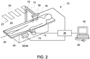
- the imaging system 10 is shown as including a gantry 12.
- the imaging system 10 may be described as a dual-energy x-ray absorptiometry (DXA) system, although it will be recognized that a variety of other systems may also be implemented in a similar manner.
- Gantry 12 includes an x-ray source 14 that projects a beam of x-rays 16 toward detector array 18.
- the gantry 12 exemplarily includes a lower end 13 that is positioned below a subject 22, such as a patient, and an upper end 15 that is positioned above the subject 22.
- the x-rays pass through the subject 22 to generate attenuated x-rays. As depicted in Fig.
- the x-ray source 14 may be secured to the upper end 15 and the x-ray detector 18 secured to the lower end 13.
- the detector 18 maybe secured to the upper end 15 and the x-ray source 14 maybe secured to the lower end 13.
- Each detector element 20 is exemplarily, but not limited to a cadmium telluride (CdTe) detector element, which produces an electrical signal that represents an intensity of the attenuated x-rays.
- CdTe cadmium telluride
- gantry 12 and/or components mounted on gantry 12 are exemplarily movable relative to the subject 22 and/or a table 46.
- Imaging controller 26 includes an x-ray controller 28 that provides power and timing signals to x-ray source 14.
- the x-ray controller 28 may further provide operational and/or control signals to the adjustable collimator 25 to shape the beam of x-rays from the source 14 in accordance with the imaging procedure to be performed.
- the x-ray beam may be shaped (collimated) as a fan beam.
- the fan beam 16 may be a narrow fan beam such as to limit the divergence between x-rays in the beam, which has been shown to improve parallax and image overlap blurring.
- the imaging controller 26 further includes a gantry motor controller 30 that controls a motion, speed, and position of gantry 12.
- gantry motor controller 30 may control a tilt angle of gantry 12.
- the gantry motor controller 30 may further operate to control a movable joint 50 between the detector 18 and the gantry 12.
- the gantry motor controller 30 may further operate to control a movable joint 54 exemplarily between the source 14 and the gantry 12.
- the table motor controller 44 is operably connected to the table 46 through a table motor 70.
- the table motor 70 is operable, under control signals from the table motor controller 44, to translate, rotate, and/or tilt the table 46 in a plurality of degrees of freedom of movement.
- the table motor 70 is operable to move the table 46 in three degrees of freedom, (e.g. horizontal, vertical, and depth translation) while in another embodiment, rotational degrees of freedom of movement (e.g. pitch, yaw, and roll) may be available. It will be recognized that the table motor 70 may include one or more mechanical or electromechanical systems to carry out these movements of the table 46, including but not limited to tack and opinion, screw, or chain driven actuators.
- the x-ray source 14 and the x-ray detector 18 may be moved in a raster pattern 24 so as to trace a series of transverse scans 27 of the subject 22 during which dual energy x-ray data is collected by the x-ray detector 18.
- the transverse scanning procedure generates either a single image or quantitative data set, form a plurality of scan images acquired across a patient, wherein the x-ray source 22 and the detector 26 are either longitudinally aligned with the superior-inferior axis of the patient or transversely from the patient's left to right. Scanning a patient using a transverse motion facilitates minimizing the time between acquisitions of adjacent scan images because the transverse direction across the patient is shorter than the longitudinal direction across the patient. Thus transverse scanning can reduce the severity of patient motion artifacts between scan images allowing the images to be more accurately merged.
- the transverse scanning motion is produced by coordination between the motion control of the gantry 12, x-ray source 14, and the x-ray detector 18 by the gantry motor controller 30 as well as control of the table 46 by the table motor controller 44 which operates the table 46 through the table motor 70.
- the x-ray source 14 produces a fan beam 16 having a plane that is exemplarily parallel to the longitudinal axis 48.
- the fan beam 16 may have a plane that is perpendicular to the longitudinal axis 48.
- the raster pattern 24 is adjusted such that there is some overlap (e.g., an overlap of 10%) between successive scan lines of the fan beam 16.
- a data acquisition system (DAS) 32 exemplarily in the imaging controller 26, samples and digitizes the data from detector elements 20 and converts the data to sampled and digitized data for subsequent processing.
- DAS 32 may be positioned adjacent to detector array 18 on gantry 12.
- Pre-processor 33 receives the sampled and digitized data from DAS 32 to pre-process the sampled and digitized data.
- pre-processing includes, but is not limited to, an offset correction, a primary speed correction, a reference channel correction, an air-calibration, and/or applying a negative logarithmic operation.
- processor is not limited to just those integrated circuits referred to in the art as a processor, but broadly refers to a controller, a microcontroller, a microcomputer, a programmable logic controller, an application specific integrated circuit, and any other programmable circuit, and these terms are used interchangeably herein.
- Pre-processor 33 pre-processes the sampled and digitized data to generate pre-processed data.
- An image processor 34 receives the pre-processed data from pre-processor 33 and performs image analysis, including that of densitometry and/or absorptiometry through one or more image processing operations.
- the acquired bone and tissue information for example, image and density information may be processed and displayed in real time though operations to the image processor 34 and/or the computer 36.
- the computer 36 exemplarily operates to store the reconstructed image in a mass storage device 38, where the mass storage device 38 may include, as non-limiting examples, a hard disk drive, a floppy disk drive, a compact disk-read/write (CD-R/W) drive, a Digital Versatile Disc (DVD) drive, a flash drive, and/or a solid-state storage device.
- the term computer is not limited to just those integrated circuits referred to in the art as a computer, but broadly refers to a processor, a microcontroller, a microcomputer, a programmable logic controller, an application specific integrated circuit, and any other programmable circuit, and these terms are used interchangeably herein. It will be recognized that any one or more of the processors and/or controllers as described herein may be performed by, or in conjunction with the computer 36, for example through the execution of computer readable code stored upon a computer readable medium accessible and executable by the computer 36.
- Computer 36 also receives commands and scanning parameters from a user, such as an operator, via a console 40 that includes a user interface device, such as a keyboard, mouse, voice-activated controller, touchscreen or any other suitable input apparatus.
- a user interface device such as a keyboard, mouse, voice-activated controller, touchscreen or any other suitable input apparatus.
- An associated display 42 allows a user, such as an operator, to observe the image and densitometry data from computer 36.
- the commands and scanning parameters are used by computer 36 to provide control signals and information the imaging controller 26, including the DAS 32, x-ray controller 28, and gantry motor controller 30.
- computer 36 may operate a table motor controller 44 exemplarily of the imaging controller 26 which controls a movable subject support, which is exemplarily a motorized table 46, to position subject 22 within gantry 12. Particularly, table motor controller 44 adjusts table 46 to move portions of subject 22.
- the system 10 is configured to operate in either a dual energy x-ray mode or a single energy x-ray mode.
- the x-ray source 14 In the single energy mode, the x-ray source 14emits x-rays at a narrow band of energies of a few keV and in the diagnostic imaging range of approximately 20-150 keV.
- the x-ray source 14 In the dual-energy mode, the x-ray source 14 emits radiation at two or more bands of energy emitted simultaneously or in rapid succession.
- the x-ray source 14 may also be configured to emit a single broadband energy of more than a few keV over the diagnostic imaging range.
- the system 10 may be switched between the dual energy mode and the single energy mode by increasing or decreasing the x-ray source 14 voltage and/or current.
- the system 10 may also be switched between the dual energy mode and the single energy mode by removing or adding a Kedge filter. It should be noted that the x-ray source 14 may emit x-rays at different energies
- the x-ray source 14 may be configured to output a fan beam 16 of x-rays.
- the x-ray source 14 may also be configured to output a pencil beam of x-rays (not shown), a cone beam of x-rays, or other configurations.
- the computer 36 controls the system 10 to operate in the single energy mode or dual-energy mode to determine the bone or tissue information of at least some of the scanned body.
- the single energy mode generally enables higher resolution images to be generated.
- the acquired images may then be used to measure, for example, bone density or other bone and tissue characteristics or content.
- the dual-energy x-ray scan may be a rectilinear scan of the entire patient body, which may be performed in a transverse-type scanning sequence as described above.
- an image of the entire body of the patient may be acquired, which includes image information relating to the bones and tissue in the body.
- the full body or total body scan of the entire body may be performed as a single scanning operation, which may be a low dose mode scan.
- individual rectangular regions of the body may be performed, which may be single sweep scans.
- the gantry motor controller 30 may further operate to control a movable joint 50 between the detector 18 and gantry 12.
- the movable joint 50 is operated by the gantry motor controller 30 to move the position of the detector exemplarily towards and away from a center point of the gantry 12 along line 52.
- the gantry motor controller 30 may operate a movable joint 54 between the source 14 and the gantry 12.
- the movable joint 52 is operated by the gantry motor controller 30 to move the position of the source 14 exemplarily towards and away from a center point of the gantry 12 along line 56.
- the movable joints 50, 54 may be any of a variety of mechanical movable joints, including, but not limited to rack-and-pinion, screw, or chain driven actuators. Operation of the movable joints 50, 54 control the SID, SOD, and OID and described in further detail herein.
- the gantry motor controller 30 is further operatively connected to a motorized gantry joint 68.
- the motorized gantry joint 68 is exemplarily operable to move the gantry C-arm 12 in coordinate space.
- the motorized gantry joint 8 maybe operable to move the C-arm 12 in between one and three dimensions.
- the motorized gantry joint 68 is operable to move the C-arm in a horizontal and a depth dimension as well.
- the motorized gantry joint 68 is operable, under the control of the gantry motor controller 30, to rotate the C-arm 12 about an axis.
- the motorized gantry joint 68 is operable, under the control of the gantry motor controller 30, to rotate the C-arm about at least two axes.
- adjustable SID, SOD, and OID may exemplarily be provided by independently driving the source and the detector, for example, in a system without a C-arm physically connecting the source and the detector.
- the at least one moveable joint may be provided on the gantry 12, e.g. c-arm, such movable joint being operable to adjust the relative position between the source 14 and the detector 18.
- a field of view (FOV) of an imaging procedure is exemplarily dependent upon the relationship between the source, the detector, and the patient.
- the FOV and image quality may exemplarily be dependent, at least in part upon the relative positions of components within the imaging system. As exemplarily depicted in Figure 3 , these include a distance between the source and the detector (SID), the distance between the source and the object as represented by the center of the ROI (SOD) and the distance between the detector and the center of the ROI (OID).
- SID source and the detector
- SOD center of the ROI
- OID the distance between the detector and the center of the ROI
- the patient's body, or other object supporting the patient, the imaging system itself, and/or the arrangement of the imaging room may create further constraints on the positions of the source and detector.
- improved imaging can be obtained by varying the positions of one or more of the source, the detector, and the table before and/or during an imaging procedure.
- the positions of the source, the detector, and the table can be varied in consideration of the ROI, the geometry of the imaging system, the size of the patient. These variations may be made inter-procedure or these variations may be made intra-procedure.
- the performance and robustness of a DEXA imaging system can be improved with refined control of the relative locations of the x-ray source 14, the x-ray detector 18, and the subject 22 (via manipulation of the table 46).
- Subjects vary greatly in size and shape.
- the source 14 is typically located at a fixed relationship below the table 46.
- the detector 18, however, can be moved towards or away from the subject 22 to accommodate the size of the subject, particularly the subject's girth. In embodiments, where the subject is thinner, the detector 18 may exemplarily be moved closer to the subject 22.
- the C-arm can be operated to increase the OID such that a larger patient may be accommodated between the detector 18 and the table 46.
- the table 46 may be moved lower; however, without a corresponding shift in the position of the x-ray source as described herein, the SOD will be reduced, resulting in a reduced FOV.
- a reduced FOV may increase imaging time, expose the subject to greater x-radiation, or be counter to imaging procedure goals.
- the SOD is reduced and while this reduces the FOV of the imaging procedure, the resolution of that imaging procedure is improved as the cells of the detector are spread across a smaller area of the patient being imaged.
- This may be particularly useful in embodiments wherein greater magnification of a smaller ROI of the patient is desired. In one example, this may be used to image particular joints for evaluation of bone degeneration.
- the imaging controller exemplarily operates to determine a scanning pattern 24, which as described above, may be a raster pattern.
- the gantry 12, table 46, the x-ray source 14 and the x-ray detector 18 are exemplarily moved to follow the determined scanning pattern 24.
- the scanning pattern 24 may include a plurality of transverse scans 27, which may exemplarily depend upon a width of a fan beam projected by the x-ray source 14 and collimator 25.
- the scanning pattern 24 may further include one or more of the adjustments to the SID, SOD, or OID as described above, for example based upon inputs from the user to control the imaging geometry or the objectives of the procedure, for example to scan a particular anatomical portion of the patient.
- a contour of the patient may be followed, for example as the transverse scans 27 of the raster pattern 24 are performed, the position of the x-ray source 14 and/or the x-ray detector 18 may be moved relative to an envelope or a contour of the subject 22 on the table 46.
- each of the transverse scans may have an SID, SOD, an OID as determined relative to the dimensions of the patient cross section at that transverse section and/or the particular investigation of the imaging.
- the imaging pattern 24 may include one or more adjustments to at least one of SID, SOD, or OID for one or more of the transverse scans 27 included therein.
- patient contour information either acquired by one or more scout images, stored patient size and/or shape data, patient height, weight, BMI, or other physical measurements can be used to determined adjustments of the source position, table position, detector position and/or position of the gantry 12.
- a digital patient model may be created and/or already stored in the patient's EMR.
- the system 10 may include an imaging device, for example, but not limited to a digital camera that acquires one or more images of the patient, the images may be acquired from one or more positions and patient size/length/volume measurements obtained from these images.
- an initial, low dose, or scout scan of the patient may be acquired from which patient measurements may be made.
- the patient contour may exemplarily be an envelope bounded by the surface of the table on one side and a depth/height (D in Fig. 3 ) above the table representing the patient.
- the contour may exemplarily be a predetermined distance or clearance height (C) above the highest portion of the patient. If more detailed models or measurements of the patient are available, the patient contour may similarly be adjusted to more accurately reflect anatomical portions of the patient relative to the table.
- the computer 36 may additionally comprise or operate all or part of the imaging controller 26, including, but not limited to the x-ray controller 28, gantry motor controller 30, DAS 32, pre-processor 33, image processor 34, and table motor controller 44. It will be recognized that these components may be implemented in one or more processors or controllers and perform the functions as described herein in coordination among such controllers or as modules or programs operating on a single computer or controller.
- a high frequency electromagnetic energy projection source configured to project high frequency electromagnetic energy toward subject 22 may be used instead of x-ray source 14.
- a detector array disposed within a gantry and configured to detect the high frequency electromagnetic energy may also be used instead of detector array 18.
- the image processor 34 stores the reconstructed images in the mass storage device 38.
- the image processor 34 transmits the image data to the computer 36 for generating useful patient information for diagnosis and evaluation.
- the computer 36 transmits the image data and/or the patient information to a display 42 communicatively coupled to the computer 36 and/or the image processor 34.
- patient information may be collected from an external source, possibly electronically, for example, as stored in an Electronic Medical Record (EMR) 43 and may also be entered by the operator of the machine.
- EMR Electronic Medical Record
- the display 42 allows the operator to evaluate the imaged anatomy.
- the display 42 may also allow the operator to select an ROI and/or request patient information, for example, via graphical user interface (GUI) for a subsequent scan or processing.
- GUI graphical user interface
- Figure 4 diagrammatically depicts an exemplary imaging geometry between a source trajectory 60 and a detector trajectory 62 with respect to a subject 22 as may be used in an embodiment as disclosed herein in the application of a CT imaging system.
- Figure 4 exemplarily represents the patient 22 positioned on the movable table 46.
- the x-ray source 14 is movable along a source trajectory 60 and a detector 18 is movable along a detector trajectory 62.
- the patient 22 is exemplarily located centrally to the source trajectory 60 and to the detector trajectory 62.
- the source trajectory 60 and the detector trajectory are exemplarily achieved by maintaining the positions of the source 14, the detector 18, and the table 46 while simultaneously rotating the source 14 and the detector 18, for example with the gantry (not depicted).
- an exemplary CT system as depicted in Fig. 4 is presented with the detector trajectory 62' modified, exemplarily to follow a contour of the moveable table 46 and the patient 22.
- the detector trajectory 62' may be achieved by changing the position of the detector 18 towards or away from an isocenter 64 of the subject 22, exemplarily about which the rotation axis of the gantry supporting the source 14 and the detector 18 is positioned. Movement of the position of the detector 18 toward and away from the isocenter 64 and/or gantry axis of rotation varies the SID and OID while providing a fixed SOD.
- the C-arm gantry defines an axis of rotation about which the source and detector are rotatable. By positioning this axis of rotation at or near an object, and by rotating the source and detector about the object, or rotating the object about the source and detector, images of the object taken at a plurality of different orientations can be obtained. These images can be combined to generate a comprehensive three-dimensional image of the object, for example using methods of image reconstruction. Such acquisitions are usually called cone-beam computed tomography (CBCT) acquisitions.
- CBCT cone-beam computed tomography
- CBCT capable systems typically provide a small field of view and thus can only 3D image a small portion of an object (e.g. patient) during a single scan.
- an object e.g. patient
- the table upon which the patient rests during the scan is typically positioned such that the anatomy of interest coincides with the 3D field of view.
- the detector and/or the source may collide with the patient because the patient is now positioned closer to the trajectories of the detector and/or the source. Moving the detector away from the center of the rotation reduces collision risk, but further reduces the diameter of any reconstructed three-dimensional image of the object.
- imaging system operators use a trial-and-error approach wherein the patient is repositioned so that no such collisions occur.
- repositioning the patient may lead to the anatomy of interest lying outside of the imaging field of view. Reduced field of view or improper patient positioning can potentially lead to additional acquisition, resulting in increased x-ray dose, prolonged medical procedure and/or additional use of chemical injectable agent.
- a subject to be imaged such as a patient
- CBCT cone beam CT
- FOV field of view
- ROI region of interest
- an adjustable collimator 25 is positioned in association with the x-ray source 14. The adjustable collimator 25 operates to shape the beam of x-rays 16 emitted from the x-ray source 14 in connection with an imaging procedure.
- the trajectory of one or both of the x-ray source 14 and the detector 18 can be controlled to accommodate the size of the patient, while reducing or preventing any collision risk between either of the source and detector with the table and/or patient.
- varying of the SID, SOD, and OID, along with achieving a change to the imaging isocenter may further be produced by adjusting the position of the table 46, either prior to an imaging procedure, or during an imaging procedure.
- Figure 5 exemplarily depicts two orientations of the source 14 and detector 18. It will be recognized that in an exemplary embodiment, the gantry C-arm which physically connects and simultaneously moves the source 14 and detector 18 are not depicted.
- the source 14 and detector 18 are exemplarily shown at two positions along the respective source trajectory 60 and detector trajectory 62'.
- x-rays are emitted in the direction between the source 14' and the detector 18' across an SID comprised of an SOD and an OID.
- the SID has been reduced due to the varying of the relative detected position along the detector trajectory 62' which moves the detector closer to the isocenter 64 of the patient (object).
- the SOD remains the same but the reduction in the OID results in an overall reduced SID at this point in the imaging procedure.
- the adjustable nature of the imaging system as disclosed herein exemplarily provides an imaging system with robust imaging capabilities which are adaptable to various imaging procedures as well as patient sizes.
- a gantry that can achieve variable SID, SOD, and OID on an interprocedure basis as well as an intraprocedure basis
- embodiments of the system as disclosed herein can be effectively used to provide imaging procedures on both infants or children as well as bariatric adults.
- interprocedure or intraprocedure adjustments to accommodate patient size were limited or not available. In exemplary embodiments this may position the source and detector close to the patient to achieve the goals of the imaging procedure while avoiding risk of collision with any of the components of the imaging system with the patient and/or table.
- the system disclosed herein may be used to perform a high resolution imaging mode, for example for joint imaging.
- the system is operated to reduce the SOD, for example by operating the movable joint 54 to position the source 14 closer to the center of the rotation axis of the gantry 12.
- the table motor 70 may be operated to position the table, and the patient support by the table, closer to the source 14. In either event, with a reduced SOD, the object is magnified, providing the ability to capture increased resolution image.
- the SID may be reduced, for example, in the case of pediatric imaging wherein the patient is smaller enabling a smaller SID.
- flux is increased at the detector elements level and special resolution can be maintained with a higher resolution detector e.g. a detector including four rows instead of a detector using two rows of detector elements.
- the adjustable collimator 25 may be operated in connection with changes in the SID, such that the beam of x-ray 16 is shaped to conform to the two dimension field of view (FOV) as is exemplarily constrained by the SID and the size of the detector array 18.
- FOV field of view
- the adjustable collimator associated with the source 14 may be used to provide other beam shapes, including, but not limited to, cone-beams, rectilinear beams, narrow fan-beams, or wide fan-beams, although a person of ordinary skill in the art will recognize other beam shapes as may exemplarily also be provided in other embodiments while remixing within the scope of the present disclosure.
Landscapes
- Health & Medical Sciences (AREA)
- Life Sciences & Earth Sciences (AREA)
- Engineering & Computer Science (AREA)
- Medical Informatics (AREA)
- Heart & Thoracic Surgery (AREA)
- Molecular Biology (AREA)
- Biophysics (AREA)
- Nuclear Medicine, Radiotherapy & Molecular Imaging (AREA)
- Optics & Photonics (AREA)
- Pathology (AREA)
- Radiology & Medical Imaging (AREA)
- Biomedical Technology (AREA)
- Physics & Mathematics (AREA)
- High Energy & Nuclear Physics (AREA)
- Surgery (AREA)
- Animal Behavior & Ethology (AREA)
- General Health & Medical Sciences (AREA)
- Public Health (AREA)
- Veterinary Medicine (AREA)
- Orthopedic Medicine & Surgery (AREA)
- Dentistry (AREA)
- Oral & Maxillofacial Surgery (AREA)
- Human Computer Interaction (AREA)
- Apparatus For Radiation Diagnosis (AREA)
Applications Claiming Priority (1)
| Application Number | Priority Date | Filing Date | Title |
|---|---|---|---|
| US15/638,499 US20190000407A1 (en) | 2017-06-30 | 2017-06-30 | Variable distance imaging |
Publications (2)
| Publication Number | Publication Date |
|---|---|
| EP3420907A2 true EP3420907A2 (fr) | 2019-01-02 |
| EP3420907A3 EP3420907A3 (fr) | 2019-05-08 |
Family
ID=62778767
Family Applications (1)
| Application Number | Title | Priority Date | Filing Date |
|---|---|---|---|
| EP18179522.0A Withdrawn EP3420907A3 (fr) | 2017-06-30 | 2018-06-25 | Imagerie à distance variable |
Country Status (5)
| Country | Link |
|---|---|
| US (1) | US20190000407A1 (fr) |
| EP (1) | EP3420907A3 (fr) |
| JP (1) | JP2019030637A (fr) |
| KR (1) | KR20190003388A (fr) |
| CN (1) | CN109223008A (fr) |
Cited By (2)
| Publication number | Priority date | Publication date | Assignee | Title |
|---|---|---|---|---|
| EP3366218B1 (fr) * | 2017-02-22 | 2021-03-31 | General Electric Company | Imagerie sid variable |
| IT202200019752A1 (it) * | 2022-09-26 | 2024-03-26 | Enrico Grendene | Metodo e apparato per aumentare la risoluzione spaziale medinate zoom meccanico / ottico in una acquisizione tomografica computerizzata con tecnica cone-beam |
Families Citing this family (21)
| Publication number | Priority date | Publication date | Assignee | Title |
|---|---|---|---|---|
| US10702235B2 (en) | 2017-06-08 | 2020-07-07 | Shanghai United Imaging Healthcare Co., Ltd. | Systems and methods for medical imaging |
| CN107049346B (zh) * | 2017-06-08 | 2021-06-15 | 上海联影医疗科技股份有限公司 | 医疗摄影控制方法、医疗摄影控制装置和医疗摄影设备 |
| DE102017223440A1 (de) | 2017-12-20 | 2019-06-27 | Siemens Healthcare Gmbh | Verfahren und Vorrichtung zur Sicherstellung einer korrekten Positionierung für eine Radiographieaufnahme |
| EP3501400B1 (fr) * | 2017-12-20 | 2022-06-08 | Siemens Healthcare GmbH | Procédé et dispositif permettant d'assurer un positionnement correct pour une image radiographique |
| IT201800007817A1 (it) * | 2018-08-03 | 2020-02-03 | De Gotzen Srl | Apparato per l’imaging digitale di una regione della testa del paziente |
| US12020822B2 (en) * | 2018-08-26 | 2024-06-25 | Siemens Healthineers International Ag | Imaging waypoints for radiation treatment |
| KR102405847B1 (ko) | 2019-01-10 | 2022-06-03 | 주식회사 엘지에너지솔루션 | 배터리 관리 장치 및 이를 포함하는 배터리 팩 |
| CN112834972A (zh) * | 2019-11-25 | 2021-05-25 | 通用电气精准医疗有限责任公司 | 用于磁共振成像系统的预扫描控制系统及方法 |
| US11172907B2 (en) | 2020-02-24 | 2021-11-16 | GE Precision Healthcare LLC | Systems and methods for cross calibration in dual energy x-ray absorptiometry |
| CN111437522B (zh) * | 2020-04-24 | 2023-11-21 | 上海联影医疗科技股份有限公司 | 一种防碰撞方法、装置、设备及存储介质 |
| US11619597B2 (en) * | 2020-05-27 | 2023-04-04 | Illinois Tool Works Inc. | Dual robot control systems for non-destructive evaluation |
| CN111991014B (zh) * | 2020-08-11 | 2024-08-02 | 上海联影医疗科技股份有限公司 | 一种c型臂及x射线机 |
| EP4275073A1 (fr) * | 2021-01-11 | 2023-11-15 | Shenzhen Xpectvision Technology Co., Ltd. | Procédés d'imagerie utilisant de multiples faisceaux de rayonnement |
| JP7468373B2 (ja) | 2021-01-19 | 2024-04-16 | 株式会社島津製作所 | X線撮影装置 |
| US20220280125A1 (en) * | 2021-03-02 | 2022-09-08 | Carestream Health, Inc. | X-ray bed |
| US11826188B2 (en) * | 2021-10-28 | 2023-11-28 | GE Precision Healthcare LLC | System and method for imaging a subject |
| WO2023093038A1 (fr) * | 2021-11-26 | 2023-06-01 | 武汉联影生命科学仪器有限公司 | Procédé d'identification de cabine de balayage, cabine de balayage, et système d'imagerie à balayage |
| CN114224371A (zh) * | 2021-12-31 | 2022-03-25 | 深圳市深图医学影像设备有限公司 | 变sid可移动式cbct |
| US11937970B2 (en) * | 2022-05-05 | 2024-03-26 | GE Precision Healthcare LLC | System and method for calibrating a camera feature detection system of an x-ray system |
| KR102502082B1 (ko) * | 2022-06-22 | 2023-02-20 | 이자성 | 동물진단용 엑스레이 촬영장치 및 그 제어방법 |
| CN115599026B (zh) * | 2022-12-14 | 2023-03-31 | 苏州阿普奇物联网科技有限公司 | 一种乳腺癌体外医疗检测系统 |
Family Cites Families (19)
| Publication number | Priority date | Publication date | Assignee | Title |
|---|---|---|---|---|
| US5305368A (en) * | 1992-09-14 | 1994-04-19 | Lunar Corporation | Method and apparatus for piece-wise radiographic scanning |
| US7016457B1 (en) * | 1998-12-31 | 2006-03-21 | General Electric Company | Multimode imaging system for generating high quality images |
| JP2001204718A (ja) * | 2000-01-25 | 2001-07-31 | Hitachi Medical Corp | 放射線撮影装置 |
| EP1379172A2 (fr) * | 2000-10-24 | 2004-01-14 | The Johns Hopkins University | Procede et appareil de balayage a absorptiometrie a rayons x en double energie, a projection multiple |
| US6666579B2 (en) * | 2000-12-28 | 2003-12-23 | Ge Medical Systems Global Technology Company, Llc | Method and apparatus for obtaining and displaying computed tomography images using a fluoroscopy imaging system |
| US6814489B2 (en) * | 2001-11-23 | 2004-11-09 | Ge Medical Systems Global Technology Company, Llc | 3D reconstruction system and method utilizing a variable X-ray source to image distance |
| JP4157455B2 (ja) * | 2003-10-08 | 2008-10-01 | 株式会社東芝 | X線診断装置及び撮像系移動制御方法 |
| US20050084147A1 (en) * | 2003-10-20 | 2005-04-21 | Groszmann Daniel E. | Method and apparatus for image reconstruction with projection images acquired in a non-circular arc |
| US7403591B2 (en) * | 2004-08-13 | 2008-07-22 | Koninklijke Philips Electronics N.V. | Alternative acquisition scheme for coronary angiography |
| US7539284B2 (en) * | 2005-02-11 | 2009-05-26 | Besson Guy M | Method and system for dynamic low dose X-ray imaging |
| CN2796650Y (zh) * | 2005-03-31 | 2006-07-19 | 西门子(中国)有限公司 | 焦点至探测器距离可调的计算机断层摄影系统 |
| JP5455446B2 (ja) * | 2009-06-02 | 2014-03-26 | キヤノン株式会社 | 放射線撮影装置、放射線撮影装置の制御方法及びプログラム |
| JP2010279532A (ja) * | 2009-06-04 | 2010-12-16 | Toshiba Corp | X線ct装置およびその制御プログラム |
| US8165266B2 (en) * | 2009-09-10 | 2012-04-24 | General Electric Company | Transverse scanning bone densitometer and detector used in same |
| JP5528956B2 (ja) * | 2010-09-08 | 2014-06-25 | 日立アロカメディカル株式会社 | 骨塩量測定装置 |
| EP2526868A1 (fr) * | 2011-05-26 | 2012-11-28 | General Electric Company | Appareil d'imagerie par rayons X doté d'une distance variable entre une source de rayons X et un objet à imager |
| JP6204584B2 (ja) * | 2013-10-07 | 2017-09-27 | メンティス インコーポレイティド | 医療処置シミュレーションに基づく放射線推定及び防護 |
| US10016171B2 (en) * | 2014-11-12 | 2018-07-10 | Epica International, Inc. | Radiological imaging device with improved functionality |
| WO2016160714A1 (fr) * | 2015-03-27 | 2016-10-06 | George Papaioannou | Système d'imagerie robotique multimodal évolutif |
-
2017
- 2017-06-30 US US15/638,499 patent/US20190000407A1/en not_active Abandoned
-
2018
- 2018-06-25 EP EP18179522.0A patent/EP3420907A3/fr not_active Withdrawn
- 2018-06-26 JP JP2018120347A patent/JP2019030637A/ja active Pending
- 2018-06-28 KR KR1020180074854A patent/KR20190003388A/ko active Search and Examination
- 2018-06-29 CN CN201810722251.9A patent/CN109223008A/zh not_active Withdrawn
Non-Patent Citations (1)
| Title |
|---|
| None |
Cited By (2)
| Publication number | Priority date | Publication date | Assignee | Title |
|---|---|---|---|---|
| EP3366218B1 (fr) * | 2017-02-22 | 2021-03-31 | General Electric Company | Imagerie sid variable |
| IT202200019752A1 (it) * | 2022-09-26 | 2024-03-26 | Enrico Grendene | Metodo e apparato per aumentare la risoluzione spaziale medinate zoom meccanico / ottico in una acquisizione tomografica computerizzata con tecnica cone-beam |
Also Published As
| Publication number | Publication date |
|---|---|
| KR20190003388A (ko) | 2019-01-09 |
| US20190000407A1 (en) | 2019-01-03 |
| EP3420907A3 (fr) | 2019-05-08 |
| JP2019030637A (ja) | 2019-02-28 |
| CN109223008A (zh) | 2019-01-18 |
Similar Documents
| Publication | Publication Date | Title |
|---|---|---|
| EP3420907A2 (fr) | Imagerie à distance variable | |
| US8649479B2 (en) | System and method for breast imaging using X-ray computed tomography | |
| US10602998B2 (en) | Methods and systems for dynamically modifying acquisition parameter during image acquisition | |
| JP5226523B2 (ja) | X線撮像に関する方法および装置 | |
| US8553837B2 (en) | Method and tomosynthesis apparatus to show a predetermined volume segment of an examination subject | |
| JP4537129B2 (ja) | トモシンセシス用途における対象物を走査するためのシステム | |
| WO2007074772A1 (fr) | Dispositif ct à rayons x | |
| JP2007144172A (ja) | モーション・アーティファクト補正と共にct画像再構成を実行する方法及びシステム | |
| EP3366218B1 (fr) | Imagerie sid variable | |
| JP2008528985A (ja) | 可変の結像ジオメトリーを有する断層撮影機 | |
| CN108601571B (zh) | Ct成像系统和用于ct成像系统的方法 | |
| US20050084147A1 (en) | Method and apparatus for image reconstruction with projection images acquired in a non-circular arc | |
| JP5196782B2 (ja) | X線ct装置およびその制御方法 | |
| US11596374B2 (en) | X-ray diagnostic apparatus and medical-information processing apparatus | |
| JP2008017964A (ja) | X線ct装置 | |
| EP4272649A1 (fr) | Système et procédé d'étalonnage d'un système de détection de caractéristiques de caméra d'un système à rayons x | |
| CN113271861B (zh) | 自适应螺旋计算机断层摄影 | |
| JP5384293B2 (ja) | X線ct装置 | |
| JP2024048198A (ja) | X線ct装置及び方法 |
Legal Events
| Date | Code | Title | Description |
|---|---|---|---|
| PUAI | Public reference made under article 153(3) epc to a published international application that has entered the european phase |
Free format text: ORIGINAL CODE: 0009012 |
|
| STAA | Information on the status of an ep patent application or granted ep patent |
Free format text: STATUS: THE APPLICATION HAS BEEN PUBLISHED |
|
| AK | Designated contracting states |
Kind code of ref document: A2 Designated state(s): AL AT BE BG CH CY CZ DE DK EE ES FI FR GB GR HR HU IE IS IT LI LT LU LV MC MK MT NL NO PL PT RO RS SE SI SK SM TR |
|
| AX | Request for extension of the european patent |
Extension state: BA ME |
|
| PUAL | Search report despatched |
Free format text: ORIGINAL CODE: 0009013 |
|
| AK | Designated contracting states |
Kind code of ref document: A3 Designated state(s): AL AT BE BG CH CY CZ DE DK EE ES FI FR GB GR HR HU IE IS IT LI LT LU LV MC MK MT NL NO PL PT RO RS SE SI SK SM TR |
|
| AX | Request for extension of the european patent |
Extension state: BA ME |
|
| RIC1 | Information provided on ipc code assigned before grant |
Ipc: A61B 6/00 20060101AFI20190329BHEP |
|
| STAA | Information on the status of an ep patent application or granted ep patent |
Free format text: STATUS: REQUEST FOR EXAMINATION WAS MADE |
|
| 17P | Request for examination filed |
Effective date: 20191108 |
|
| RBV | Designated contracting states (corrected) |
Designated state(s): AL AT BE BG CH CY CZ DE DK EE ES FI FR GB GR HR HU IE IS IT LI LT LU LV MC MK MT NL NO PL PT RO RS SE SI SK SM TR |
|
| STAA | Information on the status of an ep patent application or granted ep patent |
Free format text: STATUS: EXAMINATION IS IN PROGRESS |
|
| 17Q | First examination report despatched |
Effective date: 20200717 |
|
| STAA | Information on the status of an ep patent application or granted ep patent |
Free format text: STATUS: EXAMINATION IS IN PROGRESS |
|
| STAA | Information on the status of an ep patent application or granted ep patent |
Free format text: STATUS: THE APPLICATION IS DEEMED TO BE WITHDRAWN |
|
| 18D | Application deemed to be withdrawn |
Effective date: 20220104 |