EP3418462B1 - Stellwandvorrichtung zum mobilen einsatz und verfahren zum aufstellen einer stellwandvorrichtung - Google Patents
Stellwandvorrichtung zum mobilen einsatz und verfahren zum aufstellen einer stellwandvorrichtung Download PDFInfo
- Publication number
- EP3418462B1 EP3418462B1 EP18000542.3A EP18000542A EP3418462B1 EP 3418462 B1 EP3418462 B1 EP 3418462B1 EP 18000542 A EP18000542 A EP 18000542A EP 3418462 B1 EP3418462 B1 EP 3418462B1
- Authority
- EP
- European Patent Office
- Prior art keywords
- longitudinal side
- wall module
- wall
- centering
- module
- Prior art date
- Legal status (The legal status is an assumption and is not a legal conclusion. Google has not performed a legal analysis and makes no representation as to the accuracy of the status listed.)
- Active
Links
Images



Classifications
-
- E—FIXED CONSTRUCTIONS
- E04—BUILDING
- E04B—GENERAL BUILDING CONSTRUCTIONS; WALLS, e.g. PARTITIONS; ROOFS; FLOORS; CEILINGS; INSULATION OR OTHER PROTECTION OF BUILDINGS
- E04B2/00—Walls, e.g. partitions, for buildings; Wall construction with regard to insulation; Connections specially adapted to walls
- E04B2/74—Removable non-load-bearing partitions; Partitions with a free upper edge
- E04B2/7407—Removable non-load-bearing partitions; Partitions with a free upper edge assembled using frames with infill panels or coverings only; made-up of panels and a support structure incorporating posts
- E04B2/7416—Removable non-load-bearing partitions; Partitions with a free upper edge assembled using frames with infill panels or coverings only; made-up of panels and a support structure incorporating posts with free upper edge, e.g. for use as office space dividers
- E04B2/7422—Removable non-load-bearing partitions; Partitions with a free upper edge assembled using frames with infill panels or coverings only; made-up of panels and a support structure incorporating posts with free upper edge, e.g. for use as office space dividers with separate framed panels without intermediary support posts
- E04B2/7425—Details of connection of panels
-
- E—FIXED CONSTRUCTIONS
- E04—BUILDING
- E04B—GENERAL BUILDING CONSTRUCTIONS; WALLS, e.g. PARTITIONS; ROOFS; FLOORS; CEILINGS; INSULATION OR OTHER PROTECTION OF BUILDINGS
- E04B2/00—Walls, e.g. partitions, for buildings; Wall construction with regard to insulation; Connections specially adapted to walls
- E04B2/74—Removable non-load-bearing partitions; Partitions with a free upper edge
- E04B2/7407—Removable non-load-bearing partitions; Partitions with a free upper edge assembled using frames with infill panels or coverings only; made-up of panels and a support structure incorporating posts
- E04B2/7416—Removable non-load-bearing partitions; Partitions with a free upper edge assembled using frames with infill panels or coverings only; made-up of panels and a support structure incorporating posts with free upper edge, e.g. for use as office space dividers
- E04B2/7422—Removable non-load-bearing partitions; Partitions with a free upper edge assembled using frames with infill panels or coverings only; made-up of panels and a support structure incorporating posts with free upper edge, e.g. for use as office space dividers with separate framed panels without intermediary support posts
-
- E—FIXED CONSTRUCTIONS
- E04—BUILDING
- E04B—GENERAL BUILDING CONSTRUCTIONS; WALLS, e.g. PARTITIONS; ROOFS; FLOORS; CEILINGS; INSULATION OR OTHER PROTECTION OF BUILDINGS
- E04B2/00—Walls, e.g. partitions, for buildings; Wall construction with regard to insulation; Connections specially adapted to walls
- E04B2/74—Removable non-load-bearing partitions; Partitions with a free upper edge
- E04B2002/749—Partitions with screw-type jacks
Definitions
- the invention relates to a partition wall device for mobile use comprising a plurality of wall modules which are to be detachably connected to one another according to the preamble of claim 1 and to a method for setting up a partition wall device comprising a plurality of wall modules which are to be connected to one another, whereby a partition wall is to be formed.
- Partition wall devices are known, for example, for trade fair structures that have complex connection systems.
- DE 202 10 524 shows a partition wall with magnetic coupling.
- the main disadvantage is that several people with different tools have to be involved in assembly and dismantling.
- the object of the present invention is to provide a safe and easy-to-assemble partition wall device.
- a partition wall device for mobile use comprising a plurality of wall modules which can be detachably connected to one another, whereby a partition wall is to be formed, wherein the wall modules in particular have an aluminum hollow frame with a front plate in particular comprising plastic and/or aluminum/plastic composite material, a first connecting element on a first longitudinal side of a first wall module comprising at least one magnetic connecting means, arranged in particular in a central region of the first longitudinal side, at least one corresponding connecting element on a corresponding longitudinal side of a corresponding wall module, with a magnetizable contact means, so that a resilient connection can be established between the long sides of the wall modules, wherein a first centering means is provided on a first end region of the first long side of a first wall module, comprising a conical elevation, and a corresponding centering means is provided on a corresponding end region of a corresponding long side of a corresponding wall module, comprising a corresponding recess, in particular conical and/or rectangular, where
- the invention provides a mobile wall system that can be easily and quickly assembled by one person without assistance.
- the wall elements are connected by means of magnetic means, in particular additional security by the locking means.
- the magnetic means enables the wall element to be released without the locking means necessarily having to be activated, whereby the wall modules are essentially kept at the same height. This means that assembly by one person is safely possible.
- the first centering device is added for placing the wall module and easy tilting, whereby this can advantageously be at least partially married to a height-adjustable foot.
- the panels of the wall modules can also comprise an aluminium/plastic composite material, with a plastic core in the middle covered with an aluminium layer on both sides.
- An adjustment aid for the person building is provided by the centering device through the support surfaces and the conical design in order to position the next wall element in three spatial directions (x, y, z)
- a method for setting up a partition wall device comprising a plurality of wall modules which are to be connected to one another, whereby a partition wall is to be formed, wherein after setting up a first wall module, a corresponding wall module is to be inserted into a centering means on a first end region of the first longitudinal side of a first wall module, comprising a conical elevation, wherein the corresponding wall module has a corresponding centering means on a corresponding end region of a corresponding longitudinal side, comprising a corresponding depression, in particular conical and/or rectangular, then the corresponding wall module is tilted up at the centering means as a tilting point so far that the first longitudinal side and the corresponding longitudinal side are connected by means of a first connecting element on the first longitudinal side of the first wall module comprising at least one magnetic connecting means or a corresponding connecting element, arranged in a central region of the first longitudinal side, and at least one magnetic element or a corresponding connecting element on a corresponding longitudinal side of a
- a further securing is carried out by a locking means at a second end region of the first longitudinal side of the first wall module, and a corresponding locking means at a corresponding second end region of a corresponding longitudinal side of a corresponding wall module, in particular by a snap function and/or by a subsequent turning of a locking means.
- Fig.1 shows an exemplary partition wall device 1 according to the invention for mobile use comprising a plurality of wall modules 2 which can be detachably connected to one another, whereby a partition wall is to be formed, wherein the wall modules 2 in particular comprise an aluminum hollow frame 3 with a plastic plate 4 placed in front, a first connecting element 5 on a first longitudinal side 6 of a first wall module 7 comprising at least one magnetic connecting means 8, arranged in particular in a central region 9 of the first longitudinal side 6, at least one corresponding connecting element 10 on a corresponding longitudinal side 11 of a corresponding wall module 12, with a magnetizable contact means 13, so that a resilient connection can be established between the longitudinal sides 6, 11 of the wall modules 2
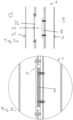
- Fig. 2a shows a section of a device 1 according to the invention with an exemplary magnetic connection means 8, wherein the magnetic connection means 8 is attached to the first longitudinal side 6, and/or a corresponding connection element 10 is designed as a recess 26 set back into which the magnetic connection means 8 can be inserted.
- Fig. 2b shows a section of a device 1 according to the invention with an exemplary magnetic connecting means 8 in the assembled state.
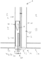
- Fig. 3a shows a section of a device 1 according to the invention with a centering means 14, which is arranged on an extended support element 21, in particular a support plate 22, which is arranged in particular on a transverse side 23 of the first wall module 7 adjacent to the long side 6, and/or a corresponding centering means of a corresponding wall module 12, in an adjacent transverse side 24, in particular as a hollow bore 25, which is to be placed on the first centering means 14, in particular the conical elevation 16.
- a centering means 14 which is arranged on an extended support element 21, in particular a support plate 22, which is arranged in particular on a transverse side 23 of the first wall module 7 adjacent to the long side 6, and/or a corresponding centering means of a corresponding wall module 12, in an adjacent transverse side 24, in particular as a hollow bore 25, which is to be placed on the first centering means 14, in particular the conical elevation 16.
- a height adjustment means 27 is arranged on a lower end region 20 of a long side 6 of a first wall module 7, in particular a threaded adjusting foot means, in particular held in an inner bore parallel to the long side, in particular by means of a tripod spring 29, which can be releasably latched into a bore 30 in the inner bore.
- Fig. 3b shows a section of a device 1 according to the invention, wherein a centering means is inserted into a device 1 in a hollow profile, wherein the tripod spring 29 is releasably engaged in a bore 30 and can be released, for example, by counter-pressing on the back of a wall module 2. It shows an exemplary combination of centering means, height-adjustable foot and locking element for insertion into an adapted end region of a long side.
- Fig. 4a shows a section of a device 1 according to the invention
- a locking means 31 is arranged on a second end region 32 of a first longitudinal side of a first wall module
- a corresponding locking means 33 is arranged on a corresponding second end region 34 of a corresponding longitudinal side of a corresponding wall module.
- Fig. 4b shows a section of a device 1 according to the invention with engaged locking means 31, 33.
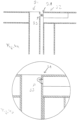
- Fig.5 shows an overview of a device 1 according to the invention, with magnetic means 8, locking means 31, centering means 14.
Landscapes
- Engineering & Computer Science (AREA)
- Architecture (AREA)
- Physics & Mathematics (AREA)
- Electromagnetism (AREA)
- Civil Engineering (AREA)
- Structural Engineering (AREA)
- Telephone Set Structure (AREA)
- Purses, Travelling Bags, Baskets, Or Suitcases (AREA)
- Casings For Electric Apparatus (AREA)
Description
- Die Erfindung betrifft eine Stellwandvorrichtung zum mobilen Einsatz umfassend mehrere Wandmodule, die lösbar miteinander zu verbinden sind nach dem Oberbegriff von Anspruch 1 und ein Verfahren zum Aufstellen einer Stellwandvorrichtung, umfassend mehrere Wandmodule, die miteinander zu verbinden sind, wodurch eine Stellwand zu bilden ist.
- Bekannt sind Stellwandvorrichtungen beispielsweise für Messeaufbauten, die komplexe Verbindungssysteme aufweisen.
DE 202 10 524 zeigt eine Stellwand mit Magnetkupplung. - Nachteilig ist es dabei insbesondere, dass mehrere Personen mit verschiedenen Werkzeugen für den Aufbau und Abbau tätig sein müssen.
- Aufgabe der vorliegenden Erfindung ist es, eine sichere und einfach aufzubauende Stellwandvorrichtung zu liefern.
- Die Aufgabe wird gelöst durch eine Stellwandvorrichtung zum mobilen Einsatz umfassend mehrere Wandmodule, die lösbar miteinander zu verbinden sind, wodurch eine Stellwand zu bilden ist, wobei die Wandmodule insbesondere einen Aluminiumhohlrahmen mit einer vorgesetzten Platte insbesondere umfassend Kunststoff und/oder Aluminium/Kunststoff-Verbundwerkstoff aufweisen, ein erstes Verbindungselement an einer ersten Längsseite eines ersten Wandmoduls umfassend zumindest ein Magnetverbindungsmittel, angeordnet insbesondere in einem Mittenbereich der ersten Längsseite, zumindest ein korrespondierendes Verbindungselement an einer korrespondierenden Längsseite eines korrespondierenden Wandmoduls, mit einem magnetisierbaren Kontaktmittel, so dass eine belastbare Verbindung zwischen den Längsseiten der Wandmodule herstellbar ist, wobei ein erstes Zentriermittel an einem ersten Endbereich der ersten Längsseite eines ersten Wandmoduls, umfassend eine konische Erhebung, und ein korrespondierendes Zentriermittel an einem korrespondierenden Endbereich einer korrespondierenden Längsseite eines korrespondierenden Wandmoduls, umfassend eine korrespondierende Eintiefung, insbesondere konisch und/oder rechteckig, vorgesehen sind, wobei die Zentriermittel an unteren Endbereichen einer Längsseite eines Wandmoduls angeordnet sind, wobei das erste Zentriermittel an einem verlängerten Unterstützungselement angeordnet ist, nämlich eine Unterstützungsplatte, dass an eine an die Längsseite angrenzenden Querseite des ersten Wandmoduls angeordnet ist, und das korrespondierendes Zentriermittel des korrespondierenden Wandmoduls, in einer angrenzenden Querseite, insbesondere als Hohlbohrung, die auf das erste Zentriermittel, nämlich die konische Erhebung aufzusetzen ist.
- Die Erfindung liefert ein mobiles Wandsystem, leicht und schnell von einer Person ohne Hilfe aufzubauen. Die Verbindung der Wandelemente erfolgt mittels Magnetmittel, insbesondere zusätzliche Sicherung durch das Schlossmittel. Das Magnetmittel ermöglicht das Loslassen des Wandelements ohne dass das Schlossmittel notwendigerweise aktiviert sein muss, wodurch die Wandmodule im Wesentlichen auf einer Höhe zu halten sind. Somit ist die Montage durch eine Person sicher möglich.
- Das erste Zentriermittel ist zum Aufsetzen des Wandmoduls und einfachem Kippen hinzugefügt, wobei dieses vorteilhaft mit einem höhenverstellbaren Fuß zumindest teilweise verheiratet sein kann.
- Die Platten der Wandmodule können auch einen Aluminium/Kunststoff-Verbundwerkstoff umfassen, wobei in der Mitte ein Kunststoffkern angeordnet ist, der auf beiden Seiten mit einer Aluminiumschicht überzogen ist.
- Eine Einstellhilfe für die aufbauende Person wird durch das Zentriermittel durch die Auflageflächen und die konische Ausführung geliefert um das nächste Wandelement in drei Raumrichtungen (x, y, z) zu positionieren
- Die Aufgabe wird ebenfalls gelöst durch ein Verfahren zum Aufstellen einer Stellwandvorrichtung, umfassend mehrere Wandmodule, die miteinander zu verbinden sind, wodurch eine Stellwand zu bilden ist, wobei nach dem Aufstellen eines ersten Wandmoduls ein korrespondierendes Wandmodul in ein Zentriermittel an einem ersten Endbereich der ersten Längsseite eines ersten Wandmoduls einzusetzen ist, umfassend eine konische Erhebung, wobei das korrespondierende Wandmodul ein korrespondierendes Zentriermittel an einem korrespondierenden Endbereich einer korrespondierenden Längsseite aufweist, umfassend eine korrespondierende Eintiefung, insbesondere konisch und/oder rechteckig, anschließend wird das korrespondierende Wandmodul an dem Zentriermittel als Kipppunkt so weit hochgekippt, dass die erste Längsseite und die korrespondierende Längsseite mittels eines ersten Verbindungselements an der ersten Längsseite des ersten Wandmoduls umfassend zumindest ein Magnetverbindungsmittel oder ein korrespondierenden Verbindungselement, angeordnet in einem Mittenbereich der ersten Längsseite, und zumindest ein Magnetelement oder ein korrespondierenden Verbindungselement an einer korrespondierenden Längsseite eines korrespondierenden Wandmoduls, mit einem magnetisierbaren Kontaktmittel, gehalten wird, so dass eine belastbare Verbindung zwischen den Längsseiten der Wandmodule herstellbar ist.
- Vorteilhaft ist es, wenn eine weitere Sicherung durch ein Schlossmittel an einem zweiten Endbereich der ersten Längsseite des ersten Wandmoduls, und ein korrespondierendes Schlossmittel an einem korrespondierenden zweiten Endbereich einer korrespondierenden Längsseite eines korrespondierenden Wandmoduls erfolgt, insbesondere durch eine Schnappfunktion und/oder durch ein anschließendes Umlegen eines Schlossmittels.
- Weitere Merkmale und Vorteile der Erfindung ergeben sich aus den Ansprüchen und der nachstehenden Beschreibung, in der Ausführungsbeispiele des Gegenstands der Erfindung in Verbindung mit den Zeichnungen näher erläutert sind.
- Es zeigen:
- Fig. 1
- eine erfindungsgemäße Vorrichtung,
- Fig. 2a
- einen Ausschnitt einer erfindungsgemäßen Vorrichtung,
- Fig. 2b
- einen Ausschnitt einer erfindungsgemäßen Vorrichtung,
- Fig. 3a
- einen Ausschnitt einer erfindungsgemäßen Vorrichtung,
- Fig. 3b
- einen Ausschnitt einer erfindungsgemäßen Vorrichtung,
- Fig. 4a
- einen Ausschnitt einer erfindungsgemäßen Vorrichtung,
- Fig. 4b
- einen Ausschnitt einer erfindungsgemäßen Vorrichtung und
- Fig. 5
- eine erfindungsgemäße Vorrichtung.
-
Fig. 1 zeigt eine beispielhafte erfindungsgemäße Stellwandvorrichtung 1 zum mobilen Einsatz umfassend mehrere Wandmodule 2, die lösbar miteinander zu verbinden sind, wodurch eine Stellwand zu bilden ist, wobei die Wandmodule 2 insbesondere einen Aluminiumhohlrahmen 3 mit einer vorgesetzten Kunststoffplatte 4 umfassen, ein erstes Verbindungselement 5 an einer ersten Längsseite 6 eines ersten Wandmoduls 7 umfassend zumindest ein Magnetverbindungsmittel 8, angeordnet insbesondere in einem Mittenbereich 9 der ersten Längsseite 6, zumindest ein korrespondierendes Verbindungselement 10 an einer korrespondierenden Längsseite 11 eines korrespondierenden Wandmoduls 12, mit einem magnetisierbaren Kontaktmittel 13, so dass eine belastbare Verbindung zwischen den Längsseiten 6, 11 der Wandmodule 2 herstellbar ist -
Fig. 2a zeigt einen Ausschnitt einer erfindungsgemäßen Vorrichtung 1 mit einem beispielhaften Magnetverbindungsmittel 8, wobei das Magnetverbindungsmittel 8 an die erste Längsseite 6 aufgelegt befestigt ist, und/oder ein korrespondierendes Verbindungselement 10 als rückversetzte Aussparung 26 ausgebildet ist, in die das Magnetverbindungsmittel 8 einführbar ist. -
Fig. 2b zeigt einen Ausschnitt einer erfindungsgemäßen Vorrichtung 1 mit einem beispielhaften Magnetverbindungsmittel 8 in zusammengefügtem Zustand. -
Fig. 3a zeigt einen Ausschnitt einer erfindungsgemäßen Vorrichtung 1 mit einem Zentriermittel 14, das an einem verlängerten Unterstützungselement 21 angeordnet ist, insbesondere eine Unterstützungsplatte 22, dass insbesondere an eine an die Längsseite 6 angrenzenden Querseite 23 des ersten Wandmoduls 7 angeordnet ist, und/oder ein korrespondierendes Zentriermittel eines korrespondierenden Wandmoduls 12, in einer angrenzenden Querseite 24, insbesondere als Hohlbohrung 25, die auf das erste Zentriermittel 14, insbesondere die konische Erhebung 16 aufzusetzen ist. Ein Höhenverstellmittel 27 ist an einem unteren Endbereich 20 einer Längsseite 6 eines ersten Wandmoduls 7 angeordnet, insbesondere ein Gewindestellfussmittel, insbesondere gehalten in einer Innenbohrung parallel zur Längsseite, insbesondere mittels einer Stativfeder 29, die in eine Bohrung 30 in der Innenbohrung lösbar einrastbar ist. -
Fig. 3b zeigt einen Ausschnitt einer erfindungsgemäßen Vorrichtung 1, wobei ein Zentriermittel in eine Vorrichtung 1 in einem Hohlprofil eingesetzt ist, wobei die Stativfeder 29 in eine Bohrung 30 lösbar eingerastet ist und beispielhaft durch ein gegendrücken auf der Rückseite eines Wandmoduls 2 auslösbar ist. Es zeigt eine beispielhafte Kombination aus Zentriermittel, höhenverstellbarem Fuß und Verrastelement zum Einstecken in einen angepasst ausgebildeten Endbereich einer Längsseite. -
Fig. 4a zeigt einen Ausschnitt einer erfindungsgemäßen Vorrichtung 1 ein Schlossmittel 31 an einem zweiten Endbereich 32 einer ersten Längsseite eines ersten Wandmoduls, und/oder ein korrespondierendes Schlossmittel 33 an einem korrespondierenden zweiten Endbereich 34 einer korrespondierenden Längsseite eines korrespondierenden Wandmoduls angeordnet ist. -
Fig. 4b zeigt einen Ausschnitt einer erfindungsgemäßen Vorrichtung 1 mit eingerastetem Schlossmittel 31, 33. -
Fig. 5 zeigt einen Überblick über eine erfindungsgemäße Vorrichtung 1, mit Magnetmittel 8, Schlossmittel 31, Zentriermittel 14. -
- 1
- Stellwandvorrichtung
- 2
- Wandmodul
- 3
- Aluminiumhohlrahmen
- 4
- Platte
- 5
- erstes Verbindungselement
- 6
- erste Längsseite
- 7
- erstes Wandmodul
- 8
- Magnetverbindungsmittel
- 9
- Mittenbereich
- 10
- korrespondierendes Verbindungselement
- 11
- korrespondierende Längsseite
- 12
- Wandmodul
- 13
- magnetisierbaren Kontaktmittel
- 14
- erstes Zentriermittel
- 15
- erster Endbereich
- 16
- konische Erhebung
- 20
- unterer Endbereich
- 21
- Unterstützungselement
- 22
- Unterstützungsplatte
- 23
- angrenzenden Querseite
- 24
- Querseite
- 26
- Aussparung
- 27
- Höhenverstellmittel
- 29
- Stativfeder
- 30
- Bohrung
- 31
- Schlossmittel
- 32
- Endbereich
- 33
- Schlossmittel
- 34
- Endbereich
Claims (8)
- Stellwandvorrichtung (1) zum mobilen Einsatz umfassend mehrere Wandmodule (2), die lösbar miteinander zu verbinden sind, wodurch eine Stellwand zu bilden ist, wobei die Wandmodule (2) insbesondere einen Aluminiumhohlrahmen (3) mit einer vorgesetzten Platte (4) insbesondere umfassend Kunststoff und/oder Aluminium/Kunststoff-Verbundwerkstoff aufweisen, ein erstes Verbindungselement (5) an einer ersten Längsseite (6) eines ersten Wandmoduls (7) umfassend zumindest ein Magnetverbindungsmittel (8), angeordnet insbesondere in einem Mittenbereich (9) der ersten Längsseite (6), zumindest ein korrespondierendes Verbindungselement (10) an einer korrespondierenden Längsseite (11) eines korrespondierenden Wandmoduls (12), mit einem magnetisierbaren Kontaktmittel (13), so dass eine belastbare Verbindung zwischen den Längsseiten (6, 11) der Wandmodule (2) herstellbar ist, dadurch gekennzeichnet, dass ein erstes Zentriermittel (14) an einem ersten Endbereich (15) der ersten Längsseite (6) eines ersten Wandmoduls (7), umfassend eine konische Erhebung (16), und ein korrespondierendes Zentriermittel an einem korrespondierenden Endbereich einer korrespondierenden Längsseite (11) eines korrespondierenden Wandmoduls (12), umfassend eine korrespondierende Eintiefung, insbesondere konisch und/oder rechteckig, vorgesehen sind, wobei die Zentriermittel (14) an unteren Endbereichen (20) einer Längsseite eines Wandmoduls (2) angeordnet sind, wobei das erste Zentriermittel (14) an einem verlängerten Unterstützungselement (21) angeordnet ist, nämlich eine Unterstützungsplatte (22), das an eine an die Längsseite (6) angrenzenden Querseite (23) des ersten Wandmoduls (7) angeordnet ist, und das korrespondierendes Zentriermittel des korrespondierenden Wandmoduls (12), in einer angrenzenden Querseite (24), insbesondere als Hohlbohrung, die auf das erste Zentriermittel (14), nämlich die konische Erhebung (16) aufzusetzen ist.
- Vorrichtung nach Anspruch 1, dadurch gekennzeichnet, dass das Magnetverbindungsmittel (8) an die erste Längsseite (6) aufgelegt befestigt ist, und/oder ein korrespondierendes Verbindungselement (10) als rückversetzte Aussparung (26) ausgebildet ist, in die das Magnetverbindungsmittel (8) einführbar ist.
- Vorrichtung nach einem der Ansprüche 1 bis 2, dadurch gekennzeichnet, dass ein Höhenverstellmittel (27) an einem unteren Endbereich (20) einer Längsseite (6) eines ersten Wandmoduls (7) angeordnet ist, insbesondere ein Gewindestellfussmittel, insbesondere gehalten in einer Innenbohrung parallel zur Längsseite, insbesondere mittels einer Stativfeder (29), die in eine Bohrung (30) in der Innenbohrung lösbar einrastbar ist.
- Vorrichtung nach einem der Ansprüche 1 bis 3, dadurch gekennzeichnet, dass das Zentriermittel (14) mittels des Höhenverstellmittels (27) an einem ersten Endbereich (20) einer Längsseite eines ersten Wandmoduls höhenverstellbar anpassbar, wobei das Zentriermittel insbesondere an einer Unterseite des Höhenverstellmittels, insbesondere einer verlängernden Unterstützungsplatte, angeordnet ist.
- Vorrichtung nach einem der Ansprüche 1 bis 4, dadurch gekennzeichnet, dass ein Schlossmittel (31) an einem zweiten Endbereich (32) einer ersten Längsseite eines ersten Wandmoduls, und/oder
ein korrespondierendes Schlossmittel (33) an einem korrespondierenden zweiten Endbereich (34) einer korrespondierenden Längsseite eines korrespondierenden Wandmoduls angeordnet ist. - Vorrichtung nach einem der Ansprüche 1 bis 5, dadurch gekennzeichnet, dass das Schlossmittel an einem gegenüberliegenden Endbereich, an dem ein Zentriermittel angeordnet ist an einem oberen Endbereich eines ersten Wandmoduls angeordnet ist.
- Verfahren zum Aufstellen einer Stellwandvorrichtung (1) nach einem der Ansprüche 1 bis 6 , umfassend mehrere Wandmodule (2), die miteinander zu verbinden sind, wodurch eine Stellwand zu bilden ist, wobei nach dem Aufstellen eines ersten Wandmoduls ein korrespondierendes Wandmodul in ein Zentriermittel an einem ersten Endbereich der ersten Längsseite eines ersten Wandmoduls einzusetzen ist, umfassend eine konische Erhebung wobei das korrespondierende Wandmodul ein korrespondierendes Zentriermittel an einem korrespondierenden Endbereich einer korrespondierenden Längsseite aufweist, umfassend eine korrespondierende Eintiefung, insbesondere konisch und/oder rechteckig, anschließend wird das korrespondierende Wandmodul an dem Zentriermittel als Kipppunkt soweit hochgekippt, dass die erste Längsseite und die korrespondierende Längsseite mittels eines ersten Verbindungselements an der ersten Längsseite (7) des ersten Wandmoduls (6) umfassend zumindest ein Magnetverbindungsmittel oder ein korrespondierenden Verbindungselement, angeordnet in einem Mittenbereich der ersten Längsseite, und zumindest ein Magnetelement oder ein korrespondierenden Verbindungselement an einer korrespondierenden Längsseite eines korrespondierenden Wandmoduls, mit einem magnetisierbaren Kontaktmittel, gehalten wird, so dass eine belastbare Verbindung zwischen den Längsseiten der Wandmodule herstellbar ist.
- Verfahren nach Anspruch 7, wobei eine weitere Sicherung durch ein Schlossmittel an einem zweiten Endbereich der ersten Längsseite des ersten Wandmoduls,
und ein korrespondierendes Schlossmittel an einem korrespondierenden zweiten Endbereich einer korrespondierenden Längsseite eines korrespondierenden Wandmoduls erfolgt, insbesondere durch eine Schnappfunktion und/oder durch ein anschließendes Umlegen eines Schlossmittels.
Applications Claiming Priority (1)
| Application Number | Priority Date | Filing Date | Title |
|---|---|---|---|
| DE102017005749.4A DE102017005749A1 (de) | 2017-06-20 | 2017-06-20 | Stellwandvorrichtung zum mobilen Einsatz und Verfahren zum Aufstellen einer Stellwandvorrichtung |
Publications (2)
| Publication Number | Publication Date |
|---|---|
| EP3418462A1 EP3418462A1 (de) | 2018-12-26 |
| EP3418462B1 true EP3418462B1 (de) | 2024-05-08 |
Family
ID=62748672
Family Applications (1)
| Application Number | Title | Priority Date | Filing Date |
|---|---|---|---|
| EP18000542.3A Active EP3418462B1 (de) | 2017-06-20 | 2018-06-20 | Stellwandvorrichtung zum mobilen einsatz und verfahren zum aufstellen einer stellwandvorrichtung |
Country Status (2)
| Country | Link |
|---|---|
| EP (1) | EP3418462B1 (de) |
| DE (1) | DE102017005749A1 (de) |
Families Citing this family (2)
| Publication number | Priority date | Publication date | Assignee | Title |
|---|---|---|---|---|
| CN110565843A (zh) * | 2019-09-10 | 2019-12-13 | 广东绿屋建筑科技工程有限公司 | 一种安装方便的装配式隔墙系统 |
| IT202100018776A1 (it) * | 2021-07-15 | 2023-01-15 | Max Services S R L | Sistema di connessione per pannelli modulari e pannello che lo incorpora |
Family Cites Families (4)
| Publication number | Priority date | Publication date | Assignee | Title |
|---|---|---|---|---|
| DE19811776A1 (de) * | 1998-03-18 | 1999-10-07 | Intersystems Werbebau Gmbh | Kupplungseinrichtung zum Verbinden von zwei Plattenelementen |
| DE20210524U1 (de) * | 2002-07-03 | 2002-10-24 | Reier, Uwe, 02991 Lauta | Stellwand mit Magnetkupplung |
| US20060107606A1 (en) * | 2004-11-22 | 2006-05-25 | Remelts Matthew D | Partition system |
| SE540168C2 (en) * | 2014-01-22 | 2018-04-17 | Ab Edsbyverken | A partition screen, a partition screen system and a method of making the partition screen |
-
2017
- 2017-06-20 DE DE102017005749.4A patent/DE102017005749A1/de not_active Withdrawn
-
2018
- 2018-06-20 EP EP18000542.3A patent/EP3418462B1/de active Active
Also Published As
| Publication number | Publication date |
|---|---|
| DE102017005749A1 (de) | 2018-12-20 |
| EP3418462A1 (de) | 2018-12-26 |
Similar Documents
| Publication | Publication Date | Title |
|---|---|---|
| CH714733A9 (de) | Fassadensystem. | |
| EP3548412B1 (de) | Verbindungseinrichtung und verfahren zum verbinden eines wandelements in einer aufzugskabine | |
| EP3365510B1 (de) | Anordnung zur wand-, decken- oder dachbekleidung eines baukörpers | |
| EP3418462A1 (de) | Stellwandvorrichtung zum mobilen einsatz und verfahren zum aufstellen einer stellwandvorrichtung | |
| EP2496777B1 (de) | Anordnung zur positionierung von abgehängten profilen im trockenbau | |
| AT522794B1 (de) | Adapter zur Halterung von Fassadenelementen | |
| DE102016111983B4 (de) | Modulares Schienensystem | |
| EP2687651A2 (de) | Verfahren zum Verstellen und/oder Befestigen von Bauteilen, ein Verbindungselement zur Ausführung des Verfahrens, ein Bausatz für das Verfahren und eine über dieses Verfahren ausgeführte Struktur | |
| DE9409626U1 (de) | Balkonkonstruktion | |
| DE202014000971U1 (de) | Profilsystem für Verglasungen | |
| DE19705252C1 (de) | Haltevorrichtung für abgehängte Bauteile | |
| EP2594718B1 (de) | Vorrichtung zum Fixieren eines Baukörpers in einer Gebäudeöffnung | |
| AT525957B1 (de) | Montageanordnung | |
| EP4108849B1 (de) | Profilsystem zur bildung einer terrassenbodenunterkonstruktion | |
| EP3865654B1 (de) | Anordnung zum abstützen von fenster- oder türelementen und verfahren zur mpntage einer solcher anordnung | |
| EP3327215B1 (de) | Pfosten-riegel-fassade | |
| DE102008039871B4 (de) | Füllelemente für Traggerüste aus Rohrelementen von Möbelbausystemen | |
| EP0813270B1 (de) | System aus Tragschienen | |
| DE102022206213A1 (de) | System und Verfahren zur beabstandeten Befestigung von Fassadenplatten | |
| EP2916093B1 (de) | Verfahren zur Befestigung eines mit Seitenblechen versehenen Wärmetauschers | |
| DE102024135047A1 (de) | Vorrichtung zur thermischen Trennung einer Fassadenhalterung | |
| DE202022103708U1 (de) | Einhängeelement für Ankerplatte eines Seitenunfallschutzes, Ankerplatte für Seitenunfallschutz sowie System aus Ankerplatte und Einhängeelement | |
| DE102016109081A1 (de) | Ankervorrichtung zur Befestigung eines Plattenelements, Plattenanordnung zur Bekleidung von Wänden mit der Ankervorrichtung sowie ein Verfahren zum Austausch des Plattenelements der Plattenanordnung | |
| DE102005024828A1 (de) | Befestigungsvorrichtung | |
| EP2537993A2 (de) | Profilsystem für eine Trennwand und Trennwand |
Legal Events
| Date | Code | Title | Description |
|---|---|---|---|
| PUAI | Public reference made under article 153(3) epc to a published international application that has entered the european phase |
Free format text: ORIGINAL CODE: 0009012 |
|
| STAA | Information on the status of an ep patent application or granted ep patent |
Free format text: STATUS: THE APPLICATION HAS BEEN PUBLISHED |
|
| AK | Designated contracting states |
Kind code of ref document: A1 Designated state(s): AL AT BE BG CH CY CZ DE DK EE ES FI FR GB GR HR HU IE IS IT LI LT LU LV MC MK MT NL NO PL PT RO RS SE SI SK SM TR |
|
| AX | Request for extension of the european patent |
Extension state: BA ME |
|
| STAA | Information on the status of an ep patent application or granted ep patent |
Free format text: STATUS: REQUEST FOR EXAMINATION WAS MADE |
|
| 17P | Request for examination filed |
Effective date: 20190626 |
|
| RBV | Designated contracting states (corrected) |
Designated state(s): AL AT BE BG CH CY CZ DE DK EE ES FI FR GB GR HR HU IE IS IT LI LT LU LV MC MK MT NL NO PL PT RO RS SE SI SK SM TR |
|
| STAA | Information on the status of an ep patent application or granted ep patent |
Free format text: STATUS: EXAMINATION IS IN PROGRESS |
|
| 17Q | First examination report despatched |
Effective date: 20210325 |
|
| RIN1 | Information on inventor provided before grant (corrected) |
Inventor name: URBAN, HEIKO |
|
| P01 | Opt-out of the competence of the unified patent court (upc) registered |
Effective date: 20230524 |
|
| GRAP | Despatch of communication of intention to grant a patent |
Free format text: ORIGINAL CODE: EPIDOSNIGR1 |
|
| STAA | Information on the status of an ep patent application or granted ep patent |
Free format text: STATUS: GRANT OF PATENT IS INTENDED |
|
| INTG | Intention to grant announced |
Effective date: 20231215 |
|
| GRAS | Grant fee paid |
Free format text: ORIGINAL CODE: EPIDOSNIGR3 |
|
| GRAA | (expected) grant |
Free format text: ORIGINAL CODE: 0009210 |
|
| STAA | Information on the status of an ep patent application or granted ep patent |
Free format text: STATUS: THE PATENT HAS BEEN GRANTED |
|
| AK | Designated contracting states |
Kind code of ref document: B1 Designated state(s): AL AT BE BG CH CY CZ DE DK EE ES FI FR GB GR HR HU IE IS IT LI LT LU LV MC MK MT NL NO PL PT RO RS SE SI SK SM TR |
|
| REG | Reference to a national code |
Ref country code: GB Ref legal event code: FG4D Free format text: NOT ENGLISH |
|
| REG | Reference to a national code |
Ref country code: CH Ref legal event code: EP |
|
| REG | Reference to a national code |
Ref country code: DE Ref legal event code: R096 Ref document number: 502018014580 Country of ref document: DE |
|
| REG | Reference to a national code |
Ref country code: IE Ref legal event code: FG4D Free format text: LANGUAGE OF EP DOCUMENT: GERMAN |
|
| REG | Reference to a national code |
Ref country code: LT Ref legal event code: MG9D |
|
| REG | Reference to a national code |
Ref country code: NL Ref legal event code: MP Effective date: 20240508 |
|
| PG25 | Lapsed in a contracting state [announced via postgrant information from national office to epo] |
Ref country code: IS Free format text: LAPSE BECAUSE OF FAILURE TO SUBMIT A TRANSLATION OF THE DESCRIPTION OR TO PAY THE FEE WITHIN THE PRESCRIBED TIME-LIMIT Effective date: 20240908 |
|
| PG25 | Lapsed in a contracting state [announced via postgrant information from national office to epo] |
Ref country code: BG Free format text: LAPSE BECAUSE OF FAILURE TO SUBMIT A TRANSLATION OF THE DESCRIPTION OR TO PAY THE FEE WITHIN THE PRESCRIBED TIME-LIMIT Effective date: 20240508 |
|
| PG25 | Lapsed in a contracting state [announced via postgrant information from national office to epo] |
Ref country code: HR Free format text: LAPSE BECAUSE OF FAILURE TO SUBMIT A TRANSLATION OF THE DESCRIPTION OR TO PAY THE FEE WITHIN THE PRESCRIBED TIME-LIMIT Effective date: 20240508 Ref country code: FI Free format text: LAPSE BECAUSE OF FAILURE TO SUBMIT A TRANSLATION OF THE DESCRIPTION OR TO PAY THE FEE WITHIN THE PRESCRIBED TIME-LIMIT Effective date: 20240508 |
|
| PG25 | Lapsed in a contracting state [announced via postgrant information from national office to epo] |
Ref country code: GR Free format text: LAPSE BECAUSE OF FAILURE TO SUBMIT A TRANSLATION OF THE DESCRIPTION OR TO PAY THE FEE WITHIN THE PRESCRIBED TIME-LIMIT Effective date: 20240809 |
|
| PG25 | Lapsed in a contracting state [announced via postgrant information from national office to epo] |
Ref country code: PT Free format text: LAPSE BECAUSE OF FAILURE TO SUBMIT A TRANSLATION OF THE DESCRIPTION OR TO PAY THE FEE WITHIN THE PRESCRIBED TIME-LIMIT Effective date: 20240909 |
|
| PG25 | Lapsed in a contracting state [announced via postgrant information from national office to epo] |
Ref country code: NL Free format text: LAPSE BECAUSE OF FAILURE TO SUBMIT A TRANSLATION OF THE DESCRIPTION OR TO PAY THE FEE WITHIN THE PRESCRIBED TIME-LIMIT Effective date: 20240508 |
|
| PG25 | Lapsed in a contracting state [announced via postgrant information from national office to epo] |
Ref country code: ES Free format text: LAPSE BECAUSE OF FAILURE TO SUBMIT A TRANSLATION OF THE DESCRIPTION OR TO PAY THE FEE WITHIN THE PRESCRIBED TIME-LIMIT Effective date: 20240508 |
|
| PG25 | Lapsed in a contracting state [announced via postgrant information from national office to epo] |
Ref country code: PL Free format text: LAPSE BECAUSE OF FAILURE TO SUBMIT A TRANSLATION OF THE DESCRIPTION OR TO PAY THE FEE WITHIN THE PRESCRIBED TIME-LIMIT Effective date: 20240508 |
|
| PG25 | Lapsed in a contracting state [announced via postgrant information from national office to epo] |
Ref country code: LV Free format text: LAPSE BECAUSE OF FAILURE TO SUBMIT A TRANSLATION OF THE DESCRIPTION OR TO PAY THE FEE WITHIN THE PRESCRIBED TIME-LIMIT Effective date: 20240508 |
|
| PG25 | Lapsed in a contracting state [announced via postgrant information from national office to epo] |
Ref country code: PT Free format text: LAPSE BECAUSE OF FAILURE TO SUBMIT A TRANSLATION OF THE DESCRIPTION OR TO PAY THE FEE WITHIN THE PRESCRIBED TIME-LIMIT Effective date: 20240909 Ref country code: PL Free format text: LAPSE BECAUSE OF FAILURE TO SUBMIT A TRANSLATION OF THE DESCRIPTION OR TO PAY THE FEE WITHIN THE PRESCRIBED TIME-LIMIT Effective date: 20240508 Ref country code: NO Free format text: LAPSE BECAUSE OF FAILURE TO SUBMIT A TRANSLATION OF THE DESCRIPTION OR TO PAY THE FEE WITHIN THE PRESCRIBED TIME-LIMIT Effective date: 20240808 Ref country code: NL Free format text: LAPSE BECAUSE OF FAILURE TO SUBMIT A TRANSLATION OF THE DESCRIPTION OR TO PAY THE FEE WITHIN THE PRESCRIBED TIME-LIMIT Effective date: 20240508 Ref country code: LV Free format text: LAPSE BECAUSE OF FAILURE TO SUBMIT A TRANSLATION OF THE DESCRIPTION OR TO PAY THE FEE WITHIN THE PRESCRIBED TIME-LIMIT Effective date: 20240508 Ref country code: IS Free format text: LAPSE BECAUSE OF FAILURE TO SUBMIT A TRANSLATION OF THE DESCRIPTION OR TO PAY THE FEE WITHIN THE PRESCRIBED TIME-LIMIT Effective date: 20240908 Ref country code: HR Free format text: LAPSE BECAUSE OF FAILURE TO SUBMIT A TRANSLATION OF THE DESCRIPTION OR TO PAY THE FEE WITHIN THE PRESCRIBED TIME-LIMIT Effective date: 20240508 Ref country code: GR Free format text: LAPSE BECAUSE OF FAILURE TO SUBMIT A TRANSLATION OF THE DESCRIPTION OR TO PAY THE FEE WITHIN THE PRESCRIBED TIME-LIMIT Effective date: 20240809 Ref country code: FI Free format text: LAPSE BECAUSE OF FAILURE TO SUBMIT A TRANSLATION OF THE DESCRIPTION OR TO PAY THE FEE WITHIN THE PRESCRIBED TIME-LIMIT Effective date: 20240508 Ref country code: ES Free format text: LAPSE BECAUSE OF FAILURE TO SUBMIT A TRANSLATION OF THE DESCRIPTION OR TO PAY THE FEE WITHIN THE PRESCRIBED TIME-LIMIT Effective date: 20240508 Ref country code: BG Free format text: LAPSE BECAUSE OF FAILURE TO SUBMIT A TRANSLATION OF THE DESCRIPTION OR TO PAY THE FEE WITHIN THE PRESCRIBED TIME-LIMIT Effective date: 20240508 Ref country code: RS Free format text: LAPSE BECAUSE OF FAILURE TO SUBMIT A TRANSLATION OF THE DESCRIPTION OR TO PAY THE FEE WITHIN THE PRESCRIBED TIME-LIMIT Effective date: 20240808 |
|
| PG25 | Lapsed in a contracting state [announced via postgrant information from national office to epo] |
Ref country code: DK Free format text: LAPSE BECAUSE OF FAILURE TO SUBMIT A TRANSLATION OF THE DESCRIPTION OR TO PAY THE FEE WITHIN THE PRESCRIBED TIME-LIMIT Effective date: 20240508 |
|
| PG25 | Lapsed in a contracting state [announced via postgrant information from national office to epo] |
Ref country code: EE Free format text: LAPSE BECAUSE OF FAILURE TO SUBMIT A TRANSLATION OF THE DESCRIPTION OR TO PAY THE FEE WITHIN THE PRESCRIBED TIME-LIMIT Effective date: 20240508 |
|
| PG25 | Lapsed in a contracting state [announced via postgrant information from national office to epo] |
Ref country code: CZ Free format text: LAPSE BECAUSE OF FAILURE TO SUBMIT A TRANSLATION OF THE DESCRIPTION OR TO PAY THE FEE WITHIN THE PRESCRIBED TIME-LIMIT Effective date: 20240508 |
|
| PG25 | Lapsed in a contracting state [announced via postgrant information from national office to epo] |
Ref country code: RO Free format text: LAPSE BECAUSE OF FAILURE TO SUBMIT A TRANSLATION OF THE DESCRIPTION OR TO PAY THE FEE WITHIN THE PRESCRIBED TIME-LIMIT Effective date: 20240508 Ref country code: SK Free format text: LAPSE BECAUSE OF FAILURE TO SUBMIT A TRANSLATION OF THE DESCRIPTION OR TO PAY THE FEE WITHIN THE PRESCRIBED TIME-LIMIT Effective date: 20240508 |
|
| PG25 | Lapsed in a contracting state [announced via postgrant information from national office to epo] |
Ref country code: SM Free format text: LAPSE BECAUSE OF FAILURE TO SUBMIT A TRANSLATION OF THE DESCRIPTION OR TO PAY THE FEE WITHIN THE PRESCRIBED TIME-LIMIT Effective date: 20240508 |
|
| PG25 | Lapsed in a contracting state [announced via postgrant information from national office to epo] |
Ref country code: SM Free format text: LAPSE BECAUSE OF FAILURE TO SUBMIT A TRANSLATION OF THE DESCRIPTION OR TO PAY THE FEE WITHIN THE PRESCRIBED TIME-LIMIT Effective date: 20240508 Ref country code: SK Free format text: LAPSE BECAUSE OF FAILURE TO SUBMIT A TRANSLATION OF THE DESCRIPTION OR TO PAY THE FEE WITHIN THE PRESCRIBED TIME-LIMIT Effective date: 20240508 Ref country code: RO Free format text: LAPSE BECAUSE OF FAILURE TO SUBMIT A TRANSLATION OF THE DESCRIPTION OR TO PAY THE FEE WITHIN THE PRESCRIBED TIME-LIMIT Effective date: 20240508 Ref country code: EE Free format text: LAPSE BECAUSE OF FAILURE TO SUBMIT A TRANSLATION OF THE DESCRIPTION OR TO PAY THE FEE WITHIN THE PRESCRIBED TIME-LIMIT Effective date: 20240508 Ref country code: DK Free format text: LAPSE BECAUSE OF FAILURE TO SUBMIT A TRANSLATION OF THE DESCRIPTION OR TO PAY THE FEE WITHIN THE PRESCRIBED TIME-LIMIT Effective date: 20240508 Ref country code: CZ Free format text: LAPSE BECAUSE OF FAILURE TO SUBMIT A TRANSLATION OF THE DESCRIPTION OR TO PAY THE FEE WITHIN THE PRESCRIBED TIME-LIMIT Effective date: 20240508 |
|
| REG | Reference to a national code |
Ref country code: CH Ref legal event code: PL |
|
| PG25 | Lapsed in a contracting state [announced via postgrant information from national office to epo] |
Ref country code: MC Free format text: LAPSE BECAUSE OF FAILURE TO SUBMIT A TRANSLATION OF THE DESCRIPTION OR TO PAY THE FEE WITHIN THE PRESCRIBED TIME-LIMIT Effective date: 20240508 Ref country code: IT Free format text: LAPSE BECAUSE OF FAILURE TO SUBMIT A TRANSLATION OF THE DESCRIPTION OR TO PAY THE FEE WITHIN THE PRESCRIBED TIME-LIMIT Effective date: 20240508 |
|
| REG | Reference to a national code |
Ref country code: DE Ref legal event code: R097 Ref document number: 502018014580 Country of ref document: DE |
|
| PG25 | Lapsed in a contracting state [announced via postgrant information from national office to epo] |
Ref country code: LU Free format text: LAPSE BECAUSE OF NON-PAYMENT OF DUE FEES Effective date: 20240620 |
|
| PLBE | No opposition filed within time limit |
Free format text: ORIGINAL CODE: 0009261 |
|
| STAA | Information on the status of an ep patent application or granted ep patent |
Free format text: STATUS: NO OPPOSITION FILED WITHIN TIME LIMIT |
|
| 26N | No opposition filed |
Effective date: 20250211 |
|
| PG25 | Lapsed in a contracting state [announced via postgrant information from national office to epo] |
Ref country code: IE Free format text: LAPSE BECAUSE OF NON-PAYMENT OF DUE FEES Effective date: 20240620 |
|
| PG25 | Lapsed in a contracting state [announced via postgrant information from national office to epo] |
Ref country code: SI Free format text: LAPSE BECAUSE OF FAILURE TO SUBMIT A TRANSLATION OF THE DESCRIPTION OR TO PAY THE FEE WITHIN THE PRESCRIBED TIME-LIMIT Effective date: 20240508 Ref country code: CH Free format text: LAPSE BECAUSE OF NON-PAYMENT OF DUE FEES Effective date: 20240630 |
|
| PGFP | Annual fee paid to national office [announced via postgrant information from national office to epo] |
Ref country code: GB Payment date: 20250627 Year of fee payment: 8 |
|
| PGFP | Annual fee paid to national office [announced via postgrant information from national office to epo] |
Ref country code: BE Payment date: 20250627 Year of fee payment: 8 |
|
| PGFP | Annual fee paid to national office [announced via postgrant information from national office to epo] |
Ref country code: FR Payment date: 20250627 Year of fee payment: 8 |
|
| PGFP | Annual fee paid to national office [announced via postgrant information from national office to epo] |
Ref country code: AT Payment date: 20250630 Year of fee payment: 8 |
|
| PG25 | Lapsed in a contracting state [announced via postgrant information from national office to epo] |
Ref country code: SE Free format text: LAPSE BECAUSE OF FAILURE TO SUBMIT A TRANSLATION OF THE DESCRIPTION OR TO PAY THE FEE WITHIN THE PRESCRIBED TIME-LIMIT Effective date: 20240508 |
|
| PGFP | Annual fee paid to national office [announced via postgrant information from national office to epo] |
Ref country code: DE Payment date: 20250813 Year of fee payment: 8 |
|
| PG25 | Lapsed in a contracting state [announced via postgrant information from national office to epo] |
Ref country code: CY Free format text: LAPSE BECAUSE OF FAILURE TO SUBMIT A TRANSLATION OF THE DESCRIPTION OR TO PAY THE FEE WITHIN THE PRESCRIBED TIME-LIMIT; INVALID AB INITIO Effective date: 20180620 |
|
| PG25 | Lapsed in a contracting state [announced via postgrant information from national office to epo] |
Ref country code: HU Free format text: LAPSE BECAUSE OF FAILURE TO SUBMIT A TRANSLATION OF THE DESCRIPTION OR TO PAY THE FEE WITHIN THE PRESCRIBED TIME-LIMIT; INVALID AB INITIO Effective date: 20180620 |