EP3418014A1 - Herstellungsverfahren eines fasermaterials, das mit thermoplastischem polymer imprägniert ist - Google Patents
Herstellungsverfahren eines fasermaterials, das mit thermoplastischem polymer imprägniert ist Download PDFInfo
- Publication number
- EP3418014A1 EP3418014A1 EP18178988.4A EP18178988A EP3418014A1 EP 3418014 A1 EP3418014 A1 EP 3418014A1 EP 18178988 A EP18178988 A EP 18178988A EP 3418014 A1 EP3418014 A1 EP 3418014A1
- Authority
- EP
- European Patent Office
- Prior art keywords
- wick
- impregnation
- polymer
- heating
- carbon
- Prior art date
- Legal status (The legal status is an assumption and is not a legal conclusion. Google has not performed a legal analysis and makes no representation as to the accuracy of the status listed.)
- Granted
Links
Images








Classifications
-
- B—PERFORMING OPERATIONS; TRANSPORTING
- B29—WORKING OF PLASTICS; WORKING OF SUBSTANCES IN A PLASTIC STATE IN GENERAL
- B29B—PREPARATION OR PRETREATMENT OF THE MATERIAL TO BE SHAPED; MAKING GRANULES OR PREFORMS; RECOVERY OF PLASTICS OR OTHER CONSTITUENTS OF WASTE MATERIAL CONTAINING PLASTICS
- B29B15/00—Pretreatment of the material to be shaped, not covered by groups B29B7/00 - B29B13/00
- B29B15/08—Pretreatment of the material to be shaped, not covered by groups B29B7/00 - B29B13/00 of reinforcements or fillers
- B29B15/10—Coating or impregnating independently of the moulding or shaping step
- B29B15/12—Coating or impregnating independently of the moulding or shaping step of reinforcements of indefinite length
- B29B15/122—Coating or impregnating independently of the moulding or shaping step of reinforcements of indefinite length with a matrix in liquid form, e.g. as melt, solution or latex
- B29B15/125—Coating or impregnating independently of the moulding or shaping step of reinforcements of indefinite length with a matrix in liquid form, e.g. as melt, solution or latex by dipping
-
- B—PERFORMING OPERATIONS; TRANSPORTING
- B29—WORKING OF PLASTICS; WORKING OF SUBSTANCES IN A PLASTIC STATE IN GENERAL
- B29B—PREPARATION OR PRETREATMENT OF THE MATERIAL TO BE SHAPED; MAKING GRANULES OR PREFORMS; RECOVERY OF PLASTICS OR OTHER CONSTITUENTS OF WASTE MATERIAL CONTAINING PLASTICS
- B29B15/00—Pretreatment of the material to be shaped, not covered by groups B29B7/00 - B29B13/00
- B29B15/08—Pretreatment of the material to be shaped, not covered by groups B29B7/00 - B29B13/00 of reinforcements or fillers
- B29B15/10—Coating or impregnating independently of the moulding or shaping step
- B29B15/12—Coating or impregnating independently of the moulding or shaping step of reinforcements of indefinite length
-
- B—PERFORMING OPERATIONS; TRANSPORTING
- B29—WORKING OF PLASTICS; WORKING OF SUBSTANCES IN A PLASTIC STATE IN GENERAL
- B29B—PREPARATION OR PRETREATMENT OF THE MATERIAL TO BE SHAPED; MAKING GRANULES OR PREFORMS; RECOVERY OF PLASTICS OR OTHER CONSTITUENTS OF WASTE MATERIAL CONTAINING PLASTICS
- B29B15/00—Pretreatment of the material to be shaped, not covered by groups B29B7/00 - B29B13/00
- B29B15/08—Pretreatment of the material to be shaped, not covered by groups B29B7/00 - B29B13/00 of reinforcements or fillers
- B29B15/10—Coating or impregnating independently of the moulding or shaping step
- B29B15/12—Coating or impregnating independently of the moulding or shaping step of reinforcements of indefinite length
- B29B15/122—Coating or impregnating independently of the moulding or shaping step of reinforcements of indefinite length with a matrix in liquid form, e.g. as melt, solution or latex
-
- B—PERFORMING OPERATIONS; TRANSPORTING
- B29—WORKING OF PLASTICS; WORKING OF SUBSTANCES IN A PLASTIC STATE IN GENERAL
- B29C—SHAPING OR JOINING OF PLASTICS; SHAPING OF MATERIAL IN A PLASTIC STATE, NOT OTHERWISE PROVIDED FOR; AFTER-TREATMENT OF THE SHAPED PRODUCTS, e.g. REPAIRING
- B29C43/00—Compression moulding, i.e. applying external pressure to flow the moulding material; Apparatus therefor
- B29C43/22—Compression moulding, i.e. applying external pressure to flow the moulding material; Apparatus therefor of articles of indefinite length
- B29C43/24—Calendering
-
- B—PERFORMING OPERATIONS; TRANSPORTING
- B29—WORKING OF PLASTICS; WORKING OF SUBSTANCES IN A PLASTIC STATE IN GENERAL
- B29C—SHAPING OR JOINING OF PLASTICS; SHAPING OF MATERIAL IN A PLASTIC STATE, NOT OTHERWISE PROVIDED FOR; AFTER-TREATMENT OF THE SHAPED PRODUCTS, e.g. REPAIRING
- B29C43/00—Compression moulding, i.e. applying external pressure to flow the moulding material; Apparatus therefor
- B29C43/32—Component parts, details or accessories; Auxiliary operations
- B29C43/44—Compression means for making articles of indefinite length
- B29C43/46—Rollers
-
- B—PERFORMING OPERATIONS; TRANSPORTING
- B29—WORKING OF PLASTICS; WORKING OF SUBSTANCES IN A PLASTIC STATE IN GENERAL
- B29C—SHAPING OR JOINING OF PLASTICS; SHAPING OF MATERIAL IN A PLASTIC STATE, NOT OTHERWISE PROVIDED FOR; AFTER-TREATMENT OF THE SHAPED PRODUCTS, e.g. REPAIRING
- B29C43/00—Compression moulding, i.e. applying external pressure to flow the moulding material; Apparatus therefor
- B29C43/32—Component parts, details or accessories; Auxiliary operations
- B29C43/52—Heating or cooling
-
- B—PERFORMING OPERATIONS; TRANSPORTING
- B29—WORKING OF PLASTICS; WORKING OF SUBSTANCES IN A PLASTIC STATE IN GENERAL
- B29C—SHAPING OR JOINING OF PLASTICS; SHAPING OF MATERIAL IN A PLASTIC STATE, NOT OTHERWISE PROVIDED FOR; AFTER-TREATMENT OF THE SHAPED PRODUCTS, e.g. REPAIRING
- B29C51/00—Shaping by thermoforming, i.e. shaping sheets or sheet like preforms after heating, e.g. shaping sheets in matched moulds or by deep-drawing; Apparatus therefor
- B29C51/12—Shaping by thermoforming, i.e. shaping sheets or sheet like preforms after heating, e.g. shaping sheets in matched moulds or by deep-drawing; Apparatus therefor of articles having inserts or reinforcements
-
- B—PERFORMING OPERATIONS; TRANSPORTING
- B29—WORKING OF PLASTICS; WORKING OF SUBSTANCES IN A PLASTIC STATE IN GENERAL
- B29C—SHAPING OR JOINING OF PLASTICS; SHAPING OF MATERIAL IN A PLASTIC STATE, NOT OTHERWISE PROVIDED FOR; AFTER-TREATMENT OF THE SHAPED PRODUCTS, e.g. REPAIRING
- B29C70/00—Shaping composites, i.e. plastics material comprising reinforcements, fillers or preformed parts, e.g. inserts
- B29C70/04—Shaping composites, i.e. plastics material comprising reinforcements, fillers or preformed parts, e.g. inserts comprising reinforcements only, e.g. self-reinforcing plastics
- B29C70/28—Shaping operations therefor
- B29C70/40—Shaping or impregnating by compression not applied
-
- B—PERFORMING OPERATIONS; TRANSPORTING
- B29—WORKING OF PLASTICS; WORKING OF SUBSTANCES IN A PLASTIC STATE IN GENERAL
- B29K—INDEXING SCHEME ASSOCIATED WITH SUBCLASSES B29B, B29C OR B29D, RELATING TO MOULDING MATERIALS OR TO MATERIALS FOR MOULDS, REINFORCEMENTS, FILLERS OR PREFORMED PARTS, e.g. INSERTS
- B29K2027/00—Use of polyvinylhalogenides or derivatives thereof as moulding material
- B29K2027/12—Use of polyvinylhalogenides or derivatives thereof as moulding material containing fluorine
- B29K2027/16—PVDF, i.e. polyvinylidene fluoride
-
- B—PERFORMING OPERATIONS; TRANSPORTING
- B29—WORKING OF PLASTICS; WORKING OF SUBSTANCES IN A PLASTIC STATE IN GENERAL
- B29K—INDEXING SCHEME ASSOCIATED WITH SUBCLASSES B29B, B29C OR B29D, RELATING TO MOULDING MATERIALS OR TO MATERIALS FOR MOULDS, REINFORCEMENTS, FILLERS OR PREFORMED PARTS, e.g. INSERTS
- B29K2027/00—Use of polyvinylhalogenides or derivatives thereof as moulding material
- B29K2027/12—Use of polyvinylhalogenides or derivatives thereof as moulding material containing fluorine
- B29K2027/18—PTFE, i.e. polytetrafluoroethylene, e.g. ePTFE, i.e. expanded polytetrafluoroethylene
-
- B—PERFORMING OPERATIONS; TRANSPORTING
- B29—WORKING OF PLASTICS; WORKING OF SUBSTANCES IN A PLASTIC STATE IN GENERAL
- B29K—INDEXING SCHEME ASSOCIATED WITH SUBCLASSES B29B, B29C OR B29D, RELATING TO MOULDING MATERIALS OR TO MATERIALS FOR MOULDS, REINFORCEMENTS, FILLERS OR PREFORMED PARTS, e.g. INSERTS
- B29K2031/00—Use of polyvinylesters or derivatives thereof as moulding material
- B29K2031/04—Polymers of vinyl acetate, e.g. PVAc, i.e. polyvinyl acetate
-
- B—PERFORMING OPERATIONS; TRANSPORTING
- B29—WORKING OF PLASTICS; WORKING OF SUBSTANCES IN A PLASTIC STATE IN GENERAL
- B29K—INDEXING SCHEME ASSOCIATED WITH SUBCLASSES B29B, B29C OR B29D, RELATING TO MOULDING MATERIALS OR TO MATERIALS FOR MOULDS, REINFORCEMENTS, FILLERS OR PREFORMED PARTS, e.g. INSERTS
- B29K2033/00—Use of polymers of unsaturated acids or derivatives thereof as moulding material
- B29K2033/04—Polymers of esters
- B29K2033/12—Polymers of methacrylic acid esters, e.g. PMMA, i.e. polymethylmethacrylate
-
- B—PERFORMING OPERATIONS; TRANSPORTING
- B29—WORKING OF PLASTICS; WORKING OF SUBSTANCES IN A PLASTIC STATE IN GENERAL
- B29K—INDEXING SCHEME ASSOCIATED WITH SUBCLASSES B29B, B29C OR B29D, RELATING TO MOULDING MATERIALS OR TO MATERIALS FOR MOULDS, REINFORCEMENTS, FILLERS OR PREFORMED PARTS, e.g. INSERTS
- B29K2067/00—Use of polyesters or derivatives thereof, as moulding material
- B29K2067/04—Polyesters derived from hydroxycarboxylic acids
- B29K2067/046—PLA, i.e. polylactic acid or polylactide
-
- B—PERFORMING OPERATIONS; TRANSPORTING
- B29—WORKING OF PLASTICS; WORKING OF SUBSTANCES IN A PLASTIC STATE IN GENERAL
- B29K—INDEXING SCHEME ASSOCIATED WITH SUBCLASSES B29B, B29C OR B29D, RELATING TO MOULDING MATERIALS OR TO MATERIALS FOR MOULDS, REINFORCEMENTS, FILLERS OR PREFORMED PARTS, e.g. INSERTS
- B29K2071/00—Use of polyethers, e.g. PEEK, i.e. polyether-etherketone or PEK, i.e. polyetherketone or derivatives thereof, as moulding material
-
- B—PERFORMING OPERATIONS; TRANSPORTING
- B29—WORKING OF PLASTICS; WORKING OF SUBSTANCES IN A PLASTIC STATE IN GENERAL
- B29K—INDEXING SCHEME ASSOCIATED WITH SUBCLASSES B29B, B29C OR B29D, RELATING TO MOULDING MATERIALS OR TO MATERIALS FOR MOULDS, REINFORCEMENTS, FILLERS OR PREFORMED PARTS, e.g. INSERTS
- B29K2077/00—Use of PA, i.e. polyamides, e.g. polyesteramides or derivatives thereof, as moulding material
-
- B—PERFORMING OPERATIONS; TRANSPORTING
- B29—WORKING OF PLASTICS; WORKING OF SUBSTANCES IN A PLASTIC STATE IN GENERAL
- B29K—INDEXING SCHEME ASSOCIATED WITH SUBCLASSES B29B, B29C OR B29D, RELATING TO MOULDING MATERIALS OR TO MATERIALS FOR MOULDS, REINFORCEMENTS, FILLERS OR PREFORMED PARTS, e.g. INSERTS
- B29K2079/00—Use of polymers having nitrogen, with or without oxygen or carbon only, in the main chain, not provided for in groups B29K2061/00 - B29K2077/00, as moulding material
- B29K2079/08—PI, i.e. polyimides or derivatives thereof
- B29K2079/085—Thermoplastic polyimides, e.g. polyesterimides, PEI, i.e. polyetherimides, or polyamideimides; Derivatives thereof
-
- B—PERFORMING OPERATIONS; TRANSPORTING
- B29—WORKING OF PLASTICS; WORKING OF SUBSTANCES IN A PLASTIC STATE IN GENERAL
- B29K—INDEXING SCHEME ASSOCIATED WITH SUBCLASSES B29B, B29C OR B29D, RELATING TO MOULDING MATERIALS OR TO MATERIALS FOR MOULDS, REINFORCEMENTS, FILLERS OR PREFORMED PARTS, e.g. INSERTS
- B29K2081/00—Use of polymers having sulfur, with or without nitrogen, oxygen or carbon only, in the main chain, as moulding material
- B29K2081/04—Polysulfides, e.g. PPS, i.e. polyphenylene sulfide or derivatives thereof
-
- B—PERFORMING OPERATIONS; TRANSPORTING
- B29—WORKING OF PLASTICS; WORKING OF SUBSTANCES IN A PLASTIC STATE IN GENERAL
- B29K—INDEXING SCHEME ASSOCIATED WITH SUBCLASSES B29B, B29C OR B29D, RELATING TO MOULDING MATERIALS OR TO MATERIALS FOR MOULDS, REINFORCEMENTS, FILLERS OR PREFORMED PARTS, e.g. INSERTS
- B29K2101/00—Use of unspecified macromolecular compounds as moulding material
- B29K2101/12—Thermoplastic materials
Definitions
- the present invention relates to a method of manufacturing a fibrous material impregnated with thermoplastic polymer.
- the invention relates to a process for manufacturing an impregnated fibrous material comprising a step of pre-impregnating a fibrous material with a thermoplastic polymer for the preparation of an impregnated fibrous material, and a heating step of the thermoplastic matrix in order to obtain strips of fibrous material impregnated homogeneously, in particular at the core, of reduced and controlled porosity, of calibrated dimensions, directly usable for the manufacture of three-dimensional composite parts.
- fibrous material means an assembly of reinforcing fibers. Before it is shaped, it is in the form of wicks. After shaping, it comes in the form of strips (or tape), or tablecloths. When the reinforcing fibers are continuous, their assembly constitutes a unidirectional reinforcement or a fabric or a nonwoven (NCF). When the fibers are short, their assembly constitutes a felt or a mat of fibers.
- Such impregnated fibrous materials are particularly intended for the production of lightweight composite materials for the manufacture of mechanical parts having a three-dimensional structure and having good mechanical and thermal properties.
- these fibrous materials are able to evacuate electrostatic charges.
- the use of flame retardant resins or flame retardant additives in non-flame resins allows impregnated fibrous materials to be fire resistant. They therefore have properties compatible with the manufacture of parts in particular in the fields of mechanics, aeronautics, nautical, automotive, oil and gas, particularly offshore, gas storage, energy, health and medical, sports and recreation, and electronics.
- Such impregnated fiber materials are also referred to as composite materials. They comprise the fibrous material, constituted by the reinforcing fibers, and a matrix constituted by the polymer impregnating the fibers.
- the primary role of this matrix is to maintain the reinforcing fibers in a compact form and to give the desired shape to the final product. This matrix also ensures the charge transfer between the fibers and therefore conditions the mechanical strength of the composite.
- Such a matrix is also used to protect the reinforcing fibers against abrasion and an aggressive environment, to control the surface appearance and to disperse any fillers between the fibers. The role of this matrix is important for the long-term behavior of the composite material, especially with regard to fatigue and creep.
- thermoplastic polymer A good quality of the three-dimensional composite parts manufactured from impregnated fibrous materials passes in particular through a control of the impregnating process of the reinforcing fibers by the thermoplastic polymer.
- band is used to designate strips of fibrous material whose width is greater than or equal to 400 mm.
- ribbon is used to designate ribbons of calibrated width and less than or equal to 400 mm.
- wick is also used to refer to the fibrous material.
- thermoplastic polymer or thermosetting polymer was carried out according to several processes which depend in particular on the nature of the polymer, the type of final desired composite material and its field of application. applications, some of these processes consisting of an impregnation step followed by a heat calendering step of the impregnated fibrous material or a drying step optionally followed by a step of melting the thermoplastic polymer.
- thermosetting polymers such as epoxy resins for example, such as described in the patent WO2012 / 066241A2 .
- thermoplastic polymers such as epoxy resins for example, such as described in the patent WO2012 / 066241A2 .
- These technologies are generally not applicable directly to the impregnation by thermoplastic polymers, because they rarely have liquid precursors.
- Steep extrusion impregnation processes of a molten polymer are suitable for the use of thermoplastic polymers of low viscosity only.
- Thermoplastic polymers in particular those with a high glass transition temperature, have a melt viscosity that is too high to allow satisfactory impregnation of fibers and semi-finished or finished products of good quality.
- Requirement US 2014 / 0005331A1 describes a process for preparing fibers impregnated with a polymer resin, the resulting strip being asymmetrical, that is to say that it has a rich polymer face and an opposite fiber-rich face.
- the process is carried out by melting with a device that allows the majority of impregnation on one of the faces.
- Another known method of pre-impregnation is the continuous passage of the fibers in an aqueous dispersion of polymer powder or aqueous dispersion of polymer particles or emulsion or aqueous polymer suspension.
- a dispersion of powders of micrometric size approximately 20 ⁇ m
- the fibers are impregnated with the polymer powder.
- the process then involves a drying step of passing the impregnated fibers through a first furnace to evaporate the water absorbed during soaking.
- a heat treatment step of passing the impregnated and dried fibers into a second heating zone at high temperature is then required to melt the polymer to adhere, disperse and coat the fibers.
- the main disadvantage of this method is the homogeneity of the deposit which is sometimes imperfect, a coating carried out only on the surface.
- the particle size of the powders usually used is fine (typically 20 ⁇ m D50 by volume) and this also increases the final cost of the impregnated ribbon or web.
- the drying step of this method induces porosity in the fibers impregnated by evaporation of the water.
- the impregnated fibrous material then needs to be shaped in the form of ribbons for example.
- the melting temperature of the polymers depends in particular on their chemical nature. It can be relatively high for polymers of polyamide 6 type, or even very high for poly (phenylene sulphide) (PPS), polyamide HT, poly (ether ether ketone) (PEEK) or poly (ether ketone ketone) polymers. (PEKK) for example.
- the heating temperature can therefore rise to temperatures higher than 250 ° C., and even higher than 350 ° C., temperatures which are much higher than the boiling point and the flash point of the solvent, which are respectively 305 ° C. and 150 ° C for benzophenone.
- the document EP 0 406 067 deposited with the joint names of Atochem and the French State, as well as the document EP 0 201 367 describe a fluidized bed impregnation technique of polymer powder.
- the fibers enter a closed fluidization vessel where, as far as EP 0 406 067 they are optionally separated from each other by means of rollers or corrugated rolls, the fibers being electrostatically charged by friction in contact with these rollers or rolls. This electrostatic charge allows the polymer powder to stick to the surface of the fibers and thus to impregnate them.
- the document WO2008 / 135663 describes, in a third variant, the production of an impregnated fiber ribbon.
- the fiber ribbon is already preformed prior to the impregnation step, in the form of a ribbon formed of fibers held together by means of contention.
- the ribbon thus preformed is previously charged with static electricity and immersed in an enclosure containing a fluidized bed of fine polymer particles suspended in the compressed air, so as to coat the ribbon with a layer of polymer coating.
- Such a document does not allow impregnation of one or more fiber strands simultaneously and continuous shaping of impregnated strands in the form of ribbons.
- EP2586585 also describes the principle of impregnating fibers by passing them into a fluidized bed of polymer particles. On the other hand, it does not describe a continuous shaping of one or more wicks thus impregnated, in the form of one or more unidirectional parallel ribbons.
- the hot calendering is carried out downstream of the impregnating device and makes it possible to homogenize the distribution of the polymer and the impregnation of the fibers but does not make it possible to obtain a homogeneously impregnated tape.
- the porosity obtained is unquantified.
- the document EP0335186 discloses the possibility of using a calender or press to compact a composite comprising impregnated metal fibers, used for manufacturing molded bodies for shielding against electromagnetic radiation. It does not disclose impregnating one or more fiber strands and continuously shaping them into one or more unidirectional parallel strips by heating after impregnation with a conductive heat and at least one heating system.
- EP 0 287 427 discloses a method of impregnation by melt with a development of the locks with restraints.
- a first area of development with embellishments allows the fibers to bloom before impregnating them by molten route and then a second heated zone of embarrassment is present.
- the document JP 2013 132890 discloses a method for producing fiber-reinforced plastic steps characterized in that the fibers pass through a thermoplastic resin cover machine, in particular a crosshead extruder and then pass the impregnated fibers into a guide comprising an upper part and a lower portion, the lower portion may include rollers and the guide being heatable.
- the fibers are introduced into a powder coating chamber in which the electrostatically charged powder particles are deposited on the fibers and then the locks are introduced into an oven in which the particles are partially melted on the fibers and the impregnated fibers are then passed around. a cooling roll.
- the document WO92 / 20521 describes the possibility of impregnating a fiber lock by passing it in a fluidized bed of thermoplastic powder particles.
- the fibers thus coated with polymer particles are heated in an oven, or a heating device, so that the polymer penetrates well and covers the fibers.
- a post-treatment of the impregnated fibrous reinforcement obtained may consist in passing it through a set of calendering rollers to improve the impregnation with the still-liquid matrix.
- Such a document does not make it possible to impregnate one or more strands of fibers and shaping, continuously, the impregnated locks in the form of one or more unidirectional parallel strips.
- the quality of the ribbons of impregnated fibrous material depends not only on the homogeneity of the impregnation of the fibers and therefore on the control and reproducibility of the porosity of the impregnated fibrous material, but also on the size and more particularly the width and thickness of the final ribbons. Regularity and control of these two dimensional parameters make it possible to improve the mechanical strength of the composite materials obtained (from the ribbons).
- the manufacture of ribbons of small width that is to say of width less than 400 mm, generally requires a slitting (that is to say a cutting) of widths greater than 400 mm, also called tablecloths.
- the ribbons thus dimensioned are then taken back to be deposited by a robot using a head.
- organic solvents usually involves the appearance of defects in the material as well as environmental, health and safety risks in general.
- the shaping by high-temperature post-treatment of the fibrous material impregnated in the form of strips, remains difficult because it does not always allow a homogeneous distribution of the polymer within the fibers, which leads to obtaining a material of lesser quality, with poorly controlled porosity.
- the slitting of plies for obtaining calibrated ribbons and the splicing of these ribbons induces an additional cost of manufacture.
- the slitting also generates significant dust problems which pollute the ribbons of impregnated fibrous materials used for robot removal and can cause malfunctions of the robots and / or imperfections on the composites. This potentially leads to robot repair costs, a shutdown of production and the scrapping of non-compliant products.
- a significant amount of fibers is deteriorated, inducing a loss of properties, and in particular a reduction in mechanical strength and conductivity, ribbons of impregnated fibrous material.
- the impregnation does not always take place at heart and if said documents cited above indicate an impregnation heart, it turns out that the porosity obtained is too important, especially for the applications listed above.
- the invention therefore aims to remedy at least one of the disadvantages of the prior art.
- the invention aims in particular to provide a method of manufacturing an impregnated fibrous material, by a high-speed pre-impregnation technique, followed by at least one step of heating the thermoplastic matrix, allowing the fusion or the maintenance in melting said thermoplastic polymer after pre-impregnation, by means of at least one heat-conducting bead member (E) and at least one heating system, excluding a heating calender, and obtaining an impregnated fibrous material having a homogeneous impregnation of the fibers, especially at the core, and controlled dimensions, with a reduced, controlled and reproducible porosity on which the performance of the final composite part depends.
- the subject of the invention is a process for manufacturing an impregnated fibrous material comprising a fibrous material made of continuous fibers and at least one thermoplastic polymer matrix, characterized in that said impregnated fibrous material is made of a single unidirectional ribbon or in a plurality of unidirectional parallel ribbons and characterized in that said method comprises, a step of pre-impregnating said fibrous material in the form of a wick or several parallel locks by said thermoplastic material and at least one heating step of the thermoplastic matrix for melting or maintaining said thermoplastic polymer in melt after pre-impregnation, said at least one heating step being carried out by means of at least one non-heating, non-heat-conducting, and at least one heating element (E), with the exception of a heating grille , said wick or said wicks being in contact with a part or the totality of the surface of said at least one piece of jig (E) and running partially or totally on the surface of said at least one piece of jig
- said method is to the exclusion of any electrostatic process in voluntary charge.
- said impregnated fibrous material is non-flexible.
- said tape is impregnated with a high level of fibers by volume, ranging from 45 to 65% by volume, preferably from 50 to 60% by volume, especially from 54 to 60%.
- the volume ratio of the fibers is constant in at least 70% of the volume of the band or ribbon, especially in at least 80% of the volume of the band or ribbon, in particular in at least 90% of the volume of the band or ribbon, more particularly in at least 95% of the volume of the tape or ribbon.
- the distribution of the fibers is homogeneous in at least 95% of the volume of the band or ribbon.
- homogeneous means that the impregnation is uniform and that there is no dry fiber, i.e., not impregnated, in at least 95% of the volume of the strip or ribbon of material fibrous impregnated.
- the measurement of the volume ratio of fibers is carried out locally on a representative elementary volume (VER).
- VER representative elementary volume
- constant means that the volume fiber ratio is constant at the nearest measurement uncertainty of plus or minus 1%.
- the pre-impregnation stage of the process of the invention may be carried out according to the techniques well known to those skilled in the art and in particular chosen from those described above if the technology does not present any problems related to the use of organic solvents or for environmental and health and safety reasons.
- the term "docking piece (E)" means any system on which the wick has the ability to scroll.
- the docking piece (E) can have any shape from the moment the wick can scroll on. It can be fixed or rotating.
- the heating system is any system that emits heat or emits radiation that can heat the wick without heating the docking piece (E).
- the mating piece (E) is therefore non-heat-conducting or does not absorb radiation emitted by heat.
- non-heat-conductive (E) -center means that the bartack (E) is made of a material incapable of absorbing and conducting heat.
- Said at least one docking piece (E) is located or included in the environment of the heating system, that is to say, it is not outside the heating system.
- Said at least one docking piece (E) is therefore in its entirety inside the heating system.
- said heating system overcomes said at least one mating piece (E).
- the heating system is at a height sufficient for the polymer present on the wick to melt or its fusion is maintained, depending on the technology used for the pre-impregnation, but without degrading said polymer.
- said heating system comprises either only said at least one mating piece (E) but may also comprise a portion of the wick, outside said mooring system (E), said wick portion being located before and / or after said docking system (E).
- the height between the heating system and the interferences is from 1 to 100 cm, preferably from 2 to 30 cm, in particular from 2 to 10 cm.
- FIG. 1 A representation of a heating system and three accomodations (E), corresponding to R ' 1 , R' 2 and R ' 3 , is presented figure 1 , without being limited in anything to this one.
- the heating system shown figure 1 is a horizontal system. However, the heating system (s) can be arranged vertically with also vertical scrolling of the wick through the jams.
- the inventors have therefore unexpectedly found that the heating step as described above carried out after the pre-impregnation stage allowed, due to the partial or total scrolling of said wick on said part (s) of (E), to obtain a surface of contact with said wick much greater than a calender and thus to exert a pressure on said wick for a longer time than with a calender, which has the effect of causing a blooming of said wick at the roller or rollers.
- the heating system only allows the pre-impregnated wick to be heated by the thermoplastic material without heating the mooring part (E), which can cause the thermoplastic polymer to melt on said wick even before its bloom and when the wick comes into contact with the first engagement (E or R ' 1 on the figure 1 ), its expansion then allows homogenous impregnation and core thereof by the molten thermoplastic polymer with a very low porosity rate thus leading to a high level of fibers in volume, especially constant in at least 70% of the volume of the band or ribbon, in particular in at least 80% of the volume of the band or ribbon, in particular in at least 90% of the volume of the band or ribbon, more particularly in at least 95% of the volume of the band or ribbon.
- homogeneous means that the impregnation is uniform and that there is no significant variation in the width of the ribbons or dry fibers in the impregnated fibrous material.
- dry fiber is meant a fiber free of polymer or not completely surrounded by polymer.
- this heating step makes it possible to perfect the impregnation of the wick carried out beforehand during the pre-impregnation stage and in particular to obtain a homogeneous and core impregnation.
- a heating calender is excluded from the scope of the invention relating to said heating system.
- Heating shell means a system of smooth cylinders or notched superposed between which the wick could circulate, said cylinders exerting pressure on said wick to smooth it and perform its shaping.
- in voluntary charge means that a potential difference is applied between the fibrous material and the powder.
- the charge is notably controlled and amplified.
- the powder grains then impregnate the fibrous material by attracting the charged powder opposite the fiber.
- the powder can be electrically charged, negatively or positively, by different means (potential difference between two metal electrodes, mechanical friction on metal parts, etc.) and charge the fiber inversely (positively or negatively).
- the method of the invention does not exclude the presence of electrostatic charges which may appear by friction of the fibrous material on the elements of the processing unit before or at the level of the tank but which are in any case involuntary loads.
- Thermoplastic, or thermoplastic polymer is understood to mean a material that is generally solid at ambient temperature, that can be semi-crystalline or amorphous, and that softens during an increase in temperature, in particular after passing its glass transition temperature (Tg). and flows at a higher temperature when it is amorphous, or can present a blunt fusion at the passage of its so-called melting temperature (Tf) when it is semi-crystalline, and which becomes solid again during a decrease in temperature below its crystallization temperature (for a semi-crystalline) and below its glass transition temperature (for an amorphous).
- Tg glass transition temperature
- Tf melting temperature
- Tg and Tf are determined by differential scanning calorimetry (DSC) according to standard 11357-2: 2013 and 11357-3: 2013 respectively.
- thermoplastic polymer As regards the polymer constituting the pre-impregnation matrix of the fibrous material, it is advantageously a thermoplastic polymer or a mixture of thermoplastic polymers.
- This polymer or mixture of thermoplastic polymers can be ground in powder form so that it can be used in a device such as a tank, in particular in a fluidized bed or in an aqueous dispersion.
- the device in the form of a tank, in particular in a fluidized bed, can be open or closed.
- thermoplastic polymer or thermoplastic polymer blend further comprises carbonaceous fillers, in particular carbon black or carbon nanofillers, preferably chosen from carbon nanofillers, in particular graphenes and / or carbon nanotubes, and or carbon nanofibrils or mixtures thereof.
- carbonaceous fillers in particular carbon black or carbon nanofillers, preferably chosen from carbon nanofillers, in particular graphenes and / or carbon nanotubes, and or carbon nanofibrils or mixtures thereof.
- said thermoplastic polymer comprises at least one additive, especially chosen from a catalyst, an antioxidant, a thermal stabilizer, a UV stabilizer, a light stabilizer, a lubricant, a filler, a plasticizer, a flame retardant, a nucleating agent , a chain extender and a dye, an electrical conductive agent, a thermal conductive agent or a mixture thereof.
- a catalyst an antioxidant, a thermal stabilizer, a UV stabilizer, a light stabilizer, a lubricant, a filler, a plasticizer, a flame retardant, a nucleating agent , a chain extender and a dye, an electrical conductive agent, a thermal conductive agent or a mixture thereof.
- said additive is chosen from a flame retardant agent, an electrical conductive agent and a thermal conductive agent.
- thermoplastic polymer or thermoplastic polymer blend may further comprise liquid crystal polymers or cyclized poly (butylene terephthalate), or mixtures containing them, such as the CBT100 resin marketed by CYCLICS CORPORATION.
- liquid crystal polymers or cyclized poly (butylene terephthalate), or mixtures containing them such as the CBT100 resin marketed by CYCLICS CORPORATION.
- the proportion by weight of polymer P1 and P2 is from 1-99% to 99-1%.
- thermoplastic polymer is a mixture
- prepreg process uses a dry powder
- this mixture is in the form of a powder obtained either by "dry blend” before introduction into the pre-impregnation vessel or by " dry blend "made directly in the tank or by grinding a compound previously made extruder.
- this mixture is composed of a powder obtained by "dry blend", before introduction into the tank or directly into the tank, and this mixture of two polymers P1 and P2 is a mixture of PEKK and PEI.
- the PEKK / PEI mixture is from 90-10% to 60-40% by weight, in particular from 90-10% to 70-30% by weight.
- the thermoplastic polymer may be the non-reactive final polymer that will impregnate the fibrous material or a reactive prepolymer, which will also impregnate the fibrous material, but is capable of reacting on itself or with another prepolymer, depending on the chain ends being carried. by said prepolymer, after pre-impregnation, or with a chain extender and in particular during heating at a heating calender.
- non-reactive polymer means that the molecular weight is no longer likely to change significantly, that is to say that its number-average molecular weight (Mn) changes by less than 50% when it is put into operation. and therefore corresponds to the final polyamide polymer of the thermoplastic matrix.
- reactive polymer means that the molecular weight of said reactive polymer will change during the implementation by reaction of prepolymers reactive with each other by condensation, substitution or with a chain extender by polyaddition and without elimination of volatile by-products to lead to the final polyamide polymer (non-reactive) of the thermoplastic matrix.
- said prepolymer may comprise or consist of at least one reactive (polyamide) prepolymer carrying on the same chain (ie on the same prepolymer), two terminal functions X 'and Y' functions respectively coreactive with each other by condensation, more particularly with X 'and Y' being amine and carboxy or carboxy and amine respectively.
- said prepolymer may comprise or consist of at least two polyamide prepolymers which are reactive with one another and each carrying two identical terminal functions X 'or Y' (identical for the same prepolymer and different between the two prepolymers), said function X 'of a prepolymer that can react only with said function Y' of the other prepolymer, in particular by condensation, more particularly with X 'and Y' being amine and carboxy or carboxy and amine respectively.
- said prepolymer may comprise or be composed of at least one prepolymer of said thermoplastic polyamide polymer carrying n terminal reactive functions X, chosen from: -NH2, -CO2H and -OH, preferably NH2 and -CO2H with wherein n is 1 to 3, preferably 1 to 2, more preferably 1 or 2, more particularly 2 and at least one Y-A'-Y chain extender, with A 'being a hydrocarbon biradical carrying 2 terminal reactive functions.
- the number-average molecular weight Mn of said final polymer of the thermoplastic matrix is preferably in a range from 10,000 to 40,000, preferably from 12,000 to 30,000. These Mn values may correspond to inherent viscosities greater than or equal to 0.8 such as determined in m-cresol according to ISO 307: 2007 but changing the solvent (use of m-cresol in place of sulfuric acid and the temperature being 20 ° C).
- Said reactive prepolymers according to the two options mentioned above have a number-average molecular weight Mn ranging from 500 to 10,000, preferably from 1,000 to 6,000, in particular from 2,500 to 6,000.
- Mn are determined in particular by the calculation from the rate of terminal functions determined by potentiometric titration in solution and the functionality of said prepolymers.
- Mn masses can also be determined by size exclusion chromatography or by NMR.
- the polyamide may be a homopolyamide or a copolyamide or a mixture thereof.
- the prepolymers constituting the matrix are chosen from polyamides (PA), in particular chosen from aliphatic polyamides, cycloaliphatic polyamides, and semi-aromatic polyamides (polyphthalamides) optionally modified with urea units, and their copolymers, polymethyl methacrylate (PPMA) and its copolymers, polyetherimides (PEI), polyphenylene sulphide (PPS), polyphenylene sulphone (PPSU), polyetherketoneketone (PEKK), Poly (ether ether ketone) (PEEK), fluorinated polymers such as polyvinylidene fluoride (PVDF).
- PA polyamides
- PPMA polymethyl methacrylate
- PEI polyetherimides
- PPS polyphenylene sulphide
- PPSU polyphenylene sulphone
- PEKK polyetherketoneketone
- PEEK Poly (ether ether ketone)
- fluorinated polymers such as polyviny
- VDF vinylidene fluoride
- CF 2 CF 2
- the VDF content must be greater than 80% by weight, or even better 90% by weight, to ensure good mechanical and chemical resistance to the structural part, especially when subjected to thermal and chemical stresses.
- the comonomer may be a fluorinated monomer such as, for example, vinyl fluoride.
- PAEKs PolyArylEtherKetone
- PEK polyether ketones PEEK poly (etheretherketone)
- PEKK poly etherketoneketone
- Tg glass transition temperature
- said thermoplastic polymer is a polymer whose glass transition temperature is such that Tg ⁇ 80 ° C, especially ⁇ 100 ° C, in particular ⁇ 120 ° C, in particular ⁇ 140 ° C, or a semi-crystalline polymer whose melting temperature Tf ⁇ 150 ° C.
- said at least one thermoplastic prepolymer is selected from polyamides, PEKK, PEI and a mixture of PEKK and PEI.
- the fibers of constitution of said fibrous material they are in particular fibers of mineral, organic or vegetable origin.
- the fibers of mineral origin mention may be made of carbon fibers, glass fibers, basalt fibers, silica fibers, or silicon carbide fibers, for example.
- the fibers of organic origin mention may be made of thermoplastic or thermosetting polymer-based fibers, such as semi-aromatic polyamide fibers, aramid fibers or polyolefin fibers, for example.
- they are based on amorphous thermoplastic polymer and have a glass transition temperature Tg greater than the Tg of the polymer or thermoplastic polymer mixture of constitution of the pre-impregnation matrix when the latter is amorphous, or greater than the Tf of the polymer or thermoplastic polymer mixture of constitution of the pre-impregnation matrix when the latter is semicrystalline.
- they are based on semi-crystalline thermoplastic polymer and have a melting temperature Tf greater than the Tg of the polymer or thermoplastic polymer mixture of constitution of the pre-impregnation matrix when the latter is amorphous, or greater than the Tf of the polymer or thermoplastic polymer mixture of constitution of the pre-impregnation matrix when the latter is semi-crystalline.
- the organic fibers constituting the fibrous material during impregnation with the thermoplastic matrix of the final composite.
- the fibers of vegetable origin mention may be made of natural fibers based on flax, hemp, lignin, bamboo, silk, especially spider, sisal, and other cellulosic fibers, in particular viscose fibers.
- These plant-based fibers can be used pure, treated or coated with a coating layer, in order to facilitate the adhesion and impregnation of the thermoplastic polymer matrix.
- the fibrous material may also be a fabric, braided or woven with fibers.
- constituent fibers can be used alone or in mixtures.
- organic fibers can be mixed with the mineral fibers to be pre-impregnated with thermoplastic polymer and form the preimpregnated fibrous material.
- the locks of organic fibers may have several grammages. They can also have several geometries.
- the fibers may be in the form of staple fibers, which then compose the felts or mats which may be in the form of strips, sheets, or pieces, or in the form of continuous fibers, which make up the 2D fabrics, the nonwovens (NCF), unidirectional (UD) or non-woven fibers or tows.
- the fibers constituting the fibrous material may also be in the form of a mixture of these reinforcing fibers of different geometries.
- the fibers are continuous.
- the fibrous material is constituted by continuous fibers of carbon, glass or silicon carbide or their mixture, in particular carbon fibers. It is used in the form of a lock or several locks.
- the polymer or mixture of thermoplastic impregnating polymers is distributed uniformly and homogeneously around the fibers.
- the thermoplastic impregnating polymer must be distributed as homogeneously as possible within the fibers in order to obtain a minimum of porosities, ie a minimum of voids between the fibers.
- porosities in this type of material can act as points of concentration of stress, when placed under tensile stress, for example, and which then form fracture initiation points of the impregnated fibrous material. and mechanically weaken it.
- a homogeneous distribution of the polymer or mixture of Polymers thus improves the mechanical strength and homogeneity of the composite material formed from these impregnated fibrous materials.
- the level of fibers in said preimpregnated fibrous material is 45 to 65% by volume, preferably 50 to 60% by volume, especially 54 to 60% by volume.
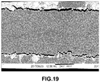
- the measurement of the impregnation rate can be carried out by image analysis (use of microscope or camera or digital camera, in particular), a cross section of the ribbon, by dividing the surface of the tape impregnated with the polymer. by the total surface of the product (surface impregnated plus surface of the porosities).
- image analysis use of microscope or camera or digital camera, in particular
- a cross section of the ribbon by dividing the surface of the tape impregnated with the polymer. by the total surface of the product (surface impregnated plus surface of the porosities).
- the porosity of said impregnated fibrous material is less than 10%, especially less than 5%, in particular less than 2%.
- the porosity rate is greater than 0% but lower than the rates mentioned above.
- the porosity rate corresponds to the closed porosity rate and can be determined either by electron microscopy or as being the relative difference between the theoretical density and the experimental density of said impregnated fibrous material as described in the examples of the present invention.
- the pre-impregnation step as already indicated above can be carried out according to the techniques well known to those skilled in the art and in particular chosen from those described above.
- the pre-impregnation stage is carried out with a system selected from a fluidized bed, a spray gun and the molten stream, especially at high speed, in particular the impregnation is carried out in a fluidized bed.
- the pre-impregnation is carried out with a system chosen from a fluidized bed, a spray gun and the molten stream, in particular at high speed, in particular the impregnation is carried out in a fluidized bed and one or more loading (s) ( E ") is (are) present upstream of said system.
- parts (E) and (E ) can be identical or different in terms of material or shape and its characteristics (diameter, length, width, height ... depending on the form).
- the pre-impregnation stage is carried out by melting, in particular by pultrusion.
- melt pre-impregnation techniques are well known to those skilled in the art and are described in the references above.
- the pre-impregnation stage is carried out in particular by extrusion at the angle head of the polymer matrix and passage of said wick or said wicks in this square head then passage in a heated die, the crosshead being optionally provided with fixed or rotary jams on which the wick scrolls thus causing a development of said wick permitting pre-impregnation of said wick.
- the pre-impregnation may in particular be carried out as described in US 2014 / 0005331A1 with the difference that the supply of resin is carried out on both sides of said wick and that there is no contact surface removing a portion of the resin on one of the two surfaces.
- the pre-impregnation step is carried out by a high speed melt, that is to say with a running speed of said wick or said wicks greater than or equal to 5 m / min, in particular greater than 9 m. / min.
- One of the other advantages of the invention to combine a pre-impregnation step and a heating step in the context of a melt pre-impregnation is that the fiber content impregnated after the heating step is included from 45% to 64% by volume, preferably from 50% to 60% by volume, in particular from 54% to 60% by volume, said level of fiber not being attained by conventional melt techniques. This also makes it possible to work with high speeds of scrolling and thus reduce production costs.
- the pre-impregnation stage is carried out in a fluidized bed.
- This system describes the use of a vessel comprising a fluidized bed to perform the pre-impregnation step and can be used in the context of the invention.
- the vessel comprising the fluidized bed is provided with at least one docking piece (E ') ( figure 2 ) which can be a compression roll ( figure 3 )).
- parts (E) and (E ') can be identical or different in terms of material or shape and its characteristics (diameter, length, width, height ... depending on the form).
- the pre-impregnation step of the fibrous material is carried out by passing one or more wicks in a continuous pre-impregnation device, comprising a tank (10) provided with at least one docking piece (E '). and comprising a fluidized bed (12) of powder of said polymer matrix.
- the powder of said polymer or polymer matrix is suspended in a gas G (air for example) introduced into the tank and circulating in the tank (10) through a hopper (11).
- the wick (s) are circulated in this fluidized bed (12).
- the tank may have any shape, in particular cylindrical or parallelepipedal, in particular a rectangular parallelepiped or a cube, advantageously a rectangular parallelepiped.
- the tank (10) can be an open or closed tank. Advantageously, it is open. In the case where the tank is closed, it is then equipped with a sealing system so that the powder of said polymer matrix can not leave said tank.
- This pre-impregnation step is therefore carried out dry, that is to say that the thermoplastic polymer matrix is in powder form, in particular in suspension in a gas, in particular air, but can not be in dispersion in a solvent or in water.
- Each wick prepreg is unwound from a reel device under the traction generated by cylinders (not shown).
- the reel device comprises a plurality of reels, each reel for unwinding a wick prepreg.
- a brake not shown
- an alignment module allows to arrange the fiber locks parallel to each other. In this way the fiber locks can not be in contact with each other, which makes it possible to avoid mechanical degradation of the fibers by friction between them.
- the fiber wick or the parallel fiber locks then pass into a tank (10), in particular comprising a fluidized bed (12), provided with a loading piece (E ') which is a compression roll (24). in the case of figure 3 .
- the fiber wick or the parallel fiber locks then spring out of the tank after pre-impregnation after any control of the residence time in the powder.
- the term "residence time in the powder” means the time during which the wick is in contact with said powder in the fluidized bed.
- the method according to the invention therefore comprises a first blooming during the pre-impregnation stage.
- piece of docking (E '), it is meant any system on which the wick has the opportunity to scroll in the tank.
- the docking piece (E ') can have any shape from the moment the wick can scroll on it.
- This pre-impregnation is performed to allow the powder of said polymer matrix to penetrate the fiber wick and adhere to the fibers sufficiently to withstand the transport of the powdered wick from the vat.
- an optional de-sizing step can be performed before the fibrous material passes into the vessel.
- sizing refers to the surface treatments applied to the reinforcing fibers at the end of the die (textile sizing) and on the fabrics (plastic sizing).
- the "textile" size applied to the fibers at the outlet of the die consists of depositing a bonding agent ensuring the cohesion of the fibers between them, reducing abrasion and facilitating subsequent handling (weaving, draping, knitting) and avoiding formation electrostatic charges.
- the "plastic" or “finish” size applied to the fabrics consists in depositing a bridging agent whose roles are to ensure a physico-chemical bond between the fibers and the resin and to protect the fiber from its environment.
- the pre-impregnation stage is carried out in a fluidized bed with control of the residence time in the powder is comprised from 0.01s to 10s, preferably from 0.1s to 5s, and in particular from 0.1s to 3s.
- the residence time of the fibrous material in the powder is essential for the pre-impregnation of said fibrous material.
- the vessel used in the process of the invention comprises a fluidized bed and said pre-impregnation stage is carried out with simultaneous expansion of said wick or said wicks between the inlet and the outlet of the vessel comprising said fluidized bed.
- inlet of the tank of said fluidized bed corresponds to the vertical tangent of the edge of the vessel which comprises the fluidized bed.
- outlet of the tank of said fluidized bed corresponds to the vertical tangent of the other edge of the vessel which comprises the fluidized bed.
- the distance between the inlet and the outlet thereof is therefore the diameter in the case of a cylindrical tank, the side in the case of a cubic tank or at the width or length in the case of a rectangular parallelepipedic tank.
- the development consists in singling out as much as possible each fiber constituting said wick of the other fibers which surround it in its nearest space. It corresponds to the transverse spreading of the wick.
- the transverse spreading or the width of the wick increases between the inlet of the fluidized bed (or of the vessel comprising the fluidized bed) and the outlet of the fluidized bed (or of the vessel comprising the fluidized bed) and thus allows improved pre-impregnation of the fibrous material.
- the fluidized bed can be open or closed, in particular it is open.
- the fluidized bed comprises at least one mating piece (E '), said bit or said bits being in contact with a part or the whole of the surface of said at least one mating piece (E').
- the figure 2 details a tank (10) comprising a fluidized bed (12) with a height-adjustable (22), height-adjustable bead piece (E ').
- the wick (21a) corresponds to the wick before pre-impregnation which is in contact with a part or the totality of the surface of said at least one piece of docking (E ') and thus scrolls partially or totally on the surface of the ejection piece (E ') (22), said system (22) being immersed in the fluidized bed where the pre-impregnation takes place. Said lock then leaves the tank (21b) after checking the residence time in the powder.
- Said bit (21a) may or may not be in contact with the inlet edge of the bowl (23a) which may be a rotating or fixed roller or a parallelepipedal edge.
- said wick (21a) is in contact or not with the edge of the tank (23a).
- the outlet edge of the vessel (23b) is a roller, in particular cylindrical and rotary.
- Said bit (21b) may or may not be in contact with the outlet edge of the bowl (23b) which may be a roller, in particular a cylindrical and rotary or fixed roll, or a parallelepipedal edge.
- said wick (21b) is in contact with the outlet edge of the vessel (23b).
- the outlet edge of the vessel (23b) is a roller, in particular cylindrical and rotary.
- said wick (21a) is in contact with the inlet edge of the tank (23a) and the outlet edge of the tank (23b) is a roller, in particular cylindrical and rotating and said wick (21b) is in contact with the outlet edge of the tank (23b), and the outlet edge of the tank (23b) is a roller, in particular cylindrical and rotating.
- said piece of docking (E ') is perpendicular to the direction of said wick or said wicks.
- Said loading part (E ') can be fixed or in rotation.
- said expansion of said wick or said wicks is performed at least at said at least one mating piece (E ').
- the blooming of the wick is thus mainly carried out at the level of the baiting piece (E ') but can also be effected at the level or edges of the bowl if there is contact between the wick and said rim. .
- said at least one mating piece (E ') is a convex, concave or cylindrical, preferably cylindrical, compression roll.
- the convex form is favorable to the development whereas the concave form is unfavorable to the blooming although it is nevertheless carried out.
- compression roll means that the wicking bit rests partially or completely on the surface of said compression roller, which induces the development of said wick.
- said at least one compression roller is of cylindrical shape and the percentage of development of said wick or said wicks between the inlet and the outlet of the tank of said fluidized bed is from 1% to 1000%, preferably 100%. % to 800% preferably 200% to 800%, preferably 400% to 800%.
- the percentage of bloom is equal to the ratio of the final width of the lock to the initial width of the lock multiplied by 100.
- the development is a function of the fibrous material used. For example, the blooming of a carbon fiber material is much greater than that of a flax fiber.
- the development is also a function of the number of fibers in the wick, their average diameter and their cohesion by the size.
- the diameter of said at least one compression roller is from 3 mm to 500 mm, preferably from 10 mm to 100 mm, in particular from 20 mm to 60 mm.
- the compression roller is cylindrical and not grooved and in particular is metallic.
- the starting piece (E ') is at least one compression roll
- a single compression roll is present in the fluidized bed and said pre-impregnation is performed at the angle ⁇ 1 formed by said wick or said wicks between the inlet of said compression roller and the vertical tangent to said compression roller.
- the angle ⁇ 1 formed by said wick or said wicks between the inlet of said compression roller and the vertical tangent to said compression roller allows the formation of an area in which the powder will concentrate thus leading to a "wedge effect" Which with the simultaneous development of the wick by said compression roller allows a pre-impregnation over a larger width of wick and thus improved pre-impregnation compared to the techniques of the improved prior art.
- the angle ⁇ 1 is from 0 to 89 °, preferably 5 ° to 85 °, preferably from 5 ° to 45 °, preferably from 5 ° to 30 °.
- an angle ⁇ 1 of 0 to 5 ° is likely to generate risks of mechanical stress, which will lead to breakage of fibers and an angle ⁇ 1 of 85 ° to 89 ° does not create enough effort mechanical to create the "corner effect".
- a value of the angle ⁇ 1 equal to 0 ° therefore corresponds to a vertical fiber. It is obvious that the height of the cylindrical compression roller is adjustable thus allowing to position the fiber vertically.
- the inlet edge of the tank (23a) is equipped with a roller, in particular a cylindrical and rotary roller, on which said wick or said wicks runs, thus leading to a development prior to the pre-impregnation.
- the blooming is initiated at the inlet edge of the tank (23a) and continues at the said one or more of the aforementioned (E ') restrictions.
- one or more restraints (E ") are present upstream of the vessel comprising the fluidized bed at which the blooming is initiated.
- the interferences (E") are as defined for (E) ').
- the blooming is initiated at the level of said one or more of the above-mentioned restraints (E ") and possibly continues at the level of the inlet edge of the tank of the tank and then at the level of the one or more said obstructions (E ') ci above defined.
- the percentage of development of said wick or said wicks between the entry of the jams (E ") and the outlet of the tank of said fluidized bed is comprised from 1% to 1000%, preferably from 100% to 800%, preferably from 200% to 800%, preferably 400% to 800%.
- the figure 3 discloses an embodiment, but not limited thereto, to a single compression roll (24) or (R 1 ), with a vessel (10) comprising a fluidized bed (12) in which a single cylindrical compression roll is present and showing the angle ⁇ 1 .
- the arrows at the fiber indicate the direction of travel of the fiber.
- the level of said powder in said fluidized bed is at least at the mid-height of said compression roller.
- said pre-impregnation is favored on one face of said wick or said wicks at the angle ⁇ 1 formed by said wick or said wicks between the inlet of said at least one compression roller R 1 and the vertical tangent with the compression roller R 1 but the expansion also allows to pre-impregnate the other face.
- the angle ⁇ 1 is as defined above.
- the mating part (E ') is at least one compression roller
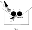
- two compression rollers R 1 and R 2 are in said fluidized bed and said pre-impregnation is carried out at the level of the angle ⁇ 1 formed by said wick or said wicks between the inlet of said compression roller R 1 and the vertical tangent to said compression roller R 1 and / or at the angle ⁇ 2 formed by said wick or said wicks between the inlet of said compression roller R 2 and the vertical tangent to said compression roller R 2 , said compression roller R 1 preceding said compression roller R 2 and said wick or said wick being able to pass above ( figure 4 and 5 ) or below ( figure 6 and 7 ) of the compression roller R 2 .
- the two compression rollers are of identical or different shape and chosen from a convex, concave or cylindrical shape.
- the two compression rollers are identical and cylindrical non-corrugated and in particular metal.
- the diameter of the two compression rollers may also be the same or different and is as defined above.
- the diameter of the two compression rollers is identical.
- the two compression rollers R 1 and R 2 can be at the same level with respect to each other and with respect to the bottom of the tank ( figures 5 and 6 ) or offset with respect to each other and with respect to the bottom of the tank, the height of the compression roller R 1 being greater or smaller than that of the compression roller R 2 with respect to the bottom of the tank ( figures 4 and 7 ).
- ⁇ 2 is from 0 to 90 °.
- said pre-impregnation is therefore performed at the angle ⁇ 1 formed by said wick or said wicks between the inlet of said compression roller R 1 and the vertical tangent to said compression roller on one face of said wick and at the angle ⁇ 2 formed by said wick or said wicks between the inlet of said compression roller R 2 and the vertical tangent to said compression roller R 2 on the opposite face of said wick which is obtained by passing above the roll R 2 .
- said bit in this embodiment is subject to expansion at each angle ⁇ 1 and ⁇ 2 .
- the figure 5 discloses an embodiment, without being limited thereto, to two compression rollers R 1 and R 2 , R 1 preceding R 2 , with a vessel (10) comprising a fluidized bed (12) in which the two rolls of cylindrical compression, at the same level and side by side, are present and showing the case where said one or more wicks emerge between said compression rollers R 1 and R 2 .
- the angle ⁇ 2 is equal to 0 and said one or more bits pass over the roll R 2 .
- the arrows at the fiber indicate the direction of travel of the fiber.
- said wick or said strands scroll (nt) between said said compression rollers R 1 and R 2 and spring (ent) after having been in contact with a part or the totality of the surface of said compression roller R 2 .
- Said pre-impregnation is therefore performed at the angle ⁇ 1 formed by said wick or said wicks between the inlet of said compression roller R 1 and the vertical tangent to said compression roller on one side of said wick and at the angle ⁇ 2 formed by said wick or said wicks between the inlet of said compression roller R 2 and the vertical tangent to said compression roller R 2 on the same face of said wick, but the expansion also makes it possible to impregnate the other side.
- said bit in this embodiment is subject to expansion at each angle ⁇ 1 and ⁇ 2 .
- the figure 6 shows an exemplary embodiment with two compression rollers R 1 and R 2 at the same level with respect to each other.
- the distance between the two compression rollers R 1 and R 2 is 0.15 mm to the length equivalent to the maximum dimension of the tank preferably between 10 mm and 50 mm and the difference in height between the two compression rollers R 1 and R 2 is from 0 to the height corresponding to the maximum height of the vessel subtracted from the diameters of the two compression rollers, preferably from 0.15mm at the height corresponding to the maximum height of the vessel subtracted from the diameters of the two compression rollers, plus preferably at a difference in height of between 10 mm and 300 mm, R 2 being the upper compression roll.
- the difference in height between two rollers is determined relative to the center of each roll.
- the level of said powder in said fluidized bed is at least located at the mid-height of said two compression rollers.
- the figure 7 discloses an embodiment, without being limited thereto, to two compression rollers R 1 and R 2 , R 1 preceding R 2 , with a vessel (10) comprising a fluidized bed (12) in which two compression rollers cylindrical at different levels are present and showing the angle ⁇ 1 and ⁇ 2 .
- the diameter of the compression rollers R 1 and R 2 is presented as identical on the figures 4 , 5 , 6 and 7 but the diameter of each cylindrical compression roller may be different, the diameter of the compression roller R 1 may be greater or smaller than that of the compression roller R 2 in the range as defined above.
- the diameter of the two compression rollers is identical.
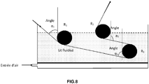
- a third compression roller R 3 is present and located between the compression rollers R 1 and R 2 in the height direction. ( figure 8 ).
- said wick or said wicks is (are) in contact with some or all of the surface of said compression roller R 1 and then with part or all of the surface of said compression roller R 3 and spring (ent) after being in contact with part or all of the surface of said compression roller R 2 .
- said pre-impregnation is performed on one face of said wick or said wicks at the angle ⁇ 1 formed by said wick or said wicks between the inlet of said at least one compression roller R 1 and the vertical tangent to compression roller R 1 and at the angle ⁇ 3 formed by said wick or said wicks and the vertical tangent to the compression roller R 3 and on the other side at the angle ⁇ 2 formed by said wick or said wicks and the vertical tangent to the compression roller R 2 .
- the angle ⁇ 2 formed by said wick or said wicks between the input of said at least a roll the compression R 2 and the vertical tangent to said compression roller R 2 is between 180 ° to 45 °, in particular 120 ° to 60 °.
- the angle ⁇ 3 is from 0 ° to 180 °, advantageously from 45 ° to 135 °.
- the figure 8 discloses an embodiment, without being limited thereto, with a vessel (10) comprising a fluidized bed (12) with two compression rollers R 1 and R 2 , R 1 preceding R 2 , and a third compression roll R 3 and showing the angles ⁇ 1 , ⁇ 2 and ⁇ 3 .
- the diameter of the compression rollers R 1 , R 2 and R 3 is presented as identical on the figure 8 but the diameter of each cylindrical compression roll may be different, or two compression rolls may have the same diameter and the third a different diameter greater or less, in the range as defined above.
- the diameter of the three compression rollers is identical.
- a second control of the development of said wick or said wicks is performed at the compression roller R 3 and a third control of the development is performed at the compression roller R 3 .
- the residence time in this third variant is as defined above.
- the level of said powder in said fluidized bed is at least located at the mid-height of said compression roller R 2 .
- said wick or said wicks is (are) in contact with some or all of the surface of said compression roll R 1 and then with a part or the entire surface of said compression roller R 2 and spring (ent) after being in contact with a part or the whole of the surface of said compression roller R 3 .
- the present invention relates to a method as defined above characterized in that a single thermoplastic polymer matrix is used and the thermoplastic polymer powder is fluidizable.
- fluidizable means that the air flow rate applied to the fluidized bed is between the minimum fluidization flow rate (Umf) and the minimum bubbling flow rate (Umf) as represented figure 10 .
- the volume diameter D90 of the thermoplastic polymer powder particles is 30 to 500 ⁇ m, advantageously 80 to 300 ⁇ m.
- the volume diameter D10 of the thermoplastic polymer powder particles is from 5 to 200 ⁇ m, advantageously from 15 to 100 ⁇ m.
- the volume diameter of the thermoplastic polymer powder particles is included in the D90 / D10 ratio, ranging from 1.5 to 50, advantageously from 2 to 10.
- the average diameter D50 by volume of the thermoplastic polymer powder particles is between 10 and 300 ⁇ m, in particular from 30 to 200 ⁇ m, more particularly from 45 to 200 ⁇ m.
- thermoplastic polymer powder particles D10, D50 and D90.
- the "D50” corresponds to the average diameter by volume, ie the value of the particle size which divides the particle population examined in exactly two parts.
- the "D90” corresponds to the value at 90% of the cumulative curve of the particle size distribution in volume.
- the "D10" corresponds to the corresponds to the size of 10% of the particle volume.
- a creel is present before the vessel comprising a fluidized bed for controlling the tension of said wick or said wicks at the inlet of the vessel comprising a fluidized bed.
- one or more difficulties are present after the tank comprising the fluidized bed.
- the step of pre-impregnating the fibrous material is carried out by passing one or more wicks in a continuous projection pre-impregnation device, comprising a tank (30), comprising one or more nozzles (s) or one or gun (s) projecting the polymer powder onto the fibrous material at the roll inlet.
- a continuous projection pre-impregnation device comprising a tank (30), comprising one or more nozzles (s) or one or gun (s) projecting the polymer powder onto the fibrous material at the roll inlet.
- the polymer (s) or polymer powder is sprayed into the tank by means of nozzle (s) or gun (s) at the part (E ') including the compression roller (input) on said fibrous material.
- the wick or wicks are circulated in this tank.
- the tank may have any shape, in particular cylindrical or parallelepipedal, in particular a rectangular parallelepiped or a cube, advantageously a rectangular parallelepiped.
- the tank may be an open or closed tank. Advantageously, it is open.
- the tank is closed, it is then equipped with a sealing system so that the polymer powder can not leave said tank.
- thermoplastic polymer matrix is in the form of powder, and projected into the air, but can not be dispersed in a solvent or in the solvent. water.
- Each wick prepreg is unwound from a reel device under the traction generated by cylinders (not shown).
- the device comprises a plurality of reels, each reel for unwinding a wick to pre-impregnate.
- each reel is provided with a brake (not shown) so as to apply tension to each fiber strand.
- an alignment module allows to arrange the fiber locks parallel to each other. In this way the fiber locks can not be in contact with each other, which makes it possible to avoid mechanical degradation of the fibers by friction between them.
- the fiber wick or the parallel fiber locks then pass into a tank (30), provided with a loading part which is a compression roll (33) in the case of the figure 12 .
- the fiber wick or the parallel fiber wicks then spring out of the tank after pre-impregnation after controlling the flow rate of said powder by said nozzle (or said nozzles) or said gun (or said ones) on said material. fibrous.
- docking part any system on which the wick has the ability to scroll in the tank.
- the docking piece can have any shape from the moment the wick can scroll on.
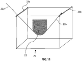
- FIG. 11 An example of a docking piece, without restricting the invention to it, is detailed in the figure 11 .
- This pre-impregnation is performed to allow the polymer powder to penetrate the fiber wick and adhere to the fibers sufficiently to withstand the transport of the powdered wick from the vat.
- the bath is provided with fixed or rotary knots on which the wick scrolls thus causing a development of said wick permitting pre-impregnation of said wick.
- the method of the invention does not exclude the presence of electrostatic charges which may appear by friction of the fibrous material on the elements of the processing unit before or at the level of the tank but which are in any case involuntary loads.
- the tank comprises at least one docking piece, said wick or said wicks being in contact with a part or the whole of the surface of said at least one piece of docking.
- an optional de-sizing step can be performed before the fibrous material passes into the tank.
- the "sizing” term refers to the surface treatments applied to the reinforcing fibers at the end of the die (textile sizing) and on the fabrics (plastic sizing).
- the "textile" size applied to the fibers at the outlet of the die consists of depositing a bonding agent ensuring the cohesion of the fibers between them, reducing abrasion and facilitating subsequent handling (weaving, draping, knitting) and avoiding formation electrostatic charges.
- the "plastic" or “finish” size applied to the fabrics consists in depositing a bridging agent whose roles are to ensure a physico-chemical bond between the fibers and the resin and to protect the fiber from its environment.
- the projection rate of the powder by the (or) nozzle (s) or the (or) gun (s) is from 10g / min to 400g / min, in particular from 20 to 150 g / min.
- This flow rate is for each gun or nozzle and may be the same or different for each gun or nozzle.
- the projection rate of the powder on fibrous material is essential for the pre-impregnation of said fibrous material.
- the diet is turbulent.
- said pre-impregnation step is performed with simultaneous expansion of said wick or said wicks between the inlet and the outlet of said vessel.
- outlet of said tank corresponds to the vertical tangent of the edge of the tank which comprises the roller or rollers with nozzle (s) or gun (s).
- outlet of said tank corresponds to the vertical tangent of the other edge of the tank which comprises the roller or rollers with nozzle (s) or gun (s).
- the distance between the inlet and the outlet of the tank corresponds to the diameter in the case of the cylinder, to the side in the case of a cube or to the width or length in the case of a rectangular parallelepiped.
- the development consists in singling out as much as possible each constituent fiber of said wick of the other fibers which surround it in its nearest space. It corresponds to the transverse spreading of the wick.
- the transverse spreading or the width of the wick increases between the inlet of the tank and the outlet of the tank and thus allows improved pre-impregnation of the fibrous material.
- the tank can be open or closed, in particular it is open.
- the tank comprises at least one docking piece, said wick or said wicks being in contact with a part or the whole of the surface of said at least one piece of docking.
- the figure 11 details a tank (20) comprising a height-adjustable bartacking piece (22).
- the wick (21a) corresponds to the wick before pre-impregnation which is in contact with a part or the totality of the surface of said at least one piece of jigging and thus scrolls partially or totally on the surface of the part of docking (22), said system (22) being immersed in the tank where the pre-impregnation takes place. Said wick then leaves the tank (21b) after controlling the projection rate of the powder at the roll inlet.
- Said bit (21a) may or may not be in contact with the edge of the bowl (23a) which may be a rotating or fixed roll or a parallelepipedal edge.
- said wick (21a) is in contact with the inlet edge of the tank (23a).
- the outlet edge of the tank (23b) is a roller, in particular cylindrical and rotating.
- Said bit (21b) may or may not be in contact with the outlet edge of the bowl (23b) which may be a roller, in particular a cylindrical and rotary or fixed roll, or a parallelepipedal edge.
- said wick (21b) is in contact with the outlet edge of the vessel (23b).
- the outlet edge of the vessel (23b) is a roller, in particular cylindrical and rotary.
- said wick (21a) is in contact with the inlet edge of the vessel (23a) and the outlet edge of the vessel (23b) is a roller, in particular cylindrical and rotary
- said wick (21b) is in contact with the inlet edge of the tank (23b), and the outlet edge of the tank (23b) is a roller, in particular cylindrical and rotating.
- said wick (21a) is in contact with the inlet edge of the vessel (23a) and a roller, in particular cylindrical and rotary, and said wick (21b) does not touch the outlet edge of the vessel ( 23b).
- said mating piece is perpendicular to the direction of said wick or said locks.
- said development of said wick or said wicks is performed at least at said at least one part of the baiting.
- the blooming of the wick is therefore mainly at the level of the mating part but can also be performed at the edge or edges of the tank if there is contact between the wick and said edge.
- said at least one mating piece is a convex, concave or cylindrical compression roll.
- the convex form is favorable to the development whereas the concave form is unfavorable to the blooming although it is nevertheless carried out.
- compression roll means that the wicking bit rests partially or completely on the surface of said compression roller, which induces the development of said wick.
- said at least one compression roller is of cylindrical shape and the percentage of development of said wick or said wicks between the inlet and the outlet of said vessel is from 1% to 1000%, preferably from 100% to 800%. preferably from 200% to 800%, preferably from 400% to 800%.
- the development is a function of the fibrous material used. For example, the blooming of a carbon fiber material is much greater than that of a flax fiber.
- the development is also a function of the number of fibers in the wick, their average diameter and their cohesion by the size.
- the diameter of said at least one compression roller is from 3 mm to 500 mm, preferably from 10 mm to 100 mm, in particular from 20 mm to 60 mm.
- the compression roller is cylindrical and not grooved and in particular is metallic.
- a single compression roller is present in the vessel and said pre-impregnation is performed at the angle ⁇ " 1 formed by said wick or said wicks between the inlet of said compression roller and the vertical tangent to said compression roller.
- the angle ⁇ " 1 formed by said wick or said wicks between the inlet of said compression roller and the vertical tangent to said compression roller allows the formation of a zone in which the powder will concentrate, thus leading to a" cooling effect ". corner "which with the simultaneous development of the wick by said compression roller allows a pre-impregnation over a larger width of the wick and therefore an improved pre-impregnation compared to the techniques of the improved prior art.
- the angle ⁇ " 1 is from 0 to 89 °, preferably 5 ° to 85 °, preferably from 5 ° to 45 °, preferably from 5 ° to 30 °.
- an angle ⁇ " 1 of between 0 and 5 ° is likely to generate risks of mechanical stress, which will lead to breakage of the fibers and an angle ⁇ " 1 of between 85 ° and 89 ° does not create enough 'mechanical effort to create' corner effect '.
- a value of the angle ⁇ " 1 equal to 0 ° therefore corresponds to a vertical fiber.It is obvious that the height of the cylindrical compression roller is adjustable thus allowing to position the fiber vertically.
- the inlet edge of the tank (23a) is equipped with a roller, in particular a cylindrical and rotary roller, on which said wick or said wicks runs, thus leading to a development prior to the pre-impregnation.
- the blooming is initiated at the inlet edge of the tank (23a) and continues at the said one or more of the aforementioned (E ') restrictions.
- one or more restraints (E ") are present upstream of the vessel comprising the fluidized bed at which the blooming is initiated.
- the interferences (E") are as defined for (E) ').
- the blooming is initiated at the level of said one or more aforementioned jams (E ") and possibly continues at the level of the inlet edge of the tank and then at the level of said one or more of the aforementioned obstacles (E ') .
- the percentage of development of said wick or said wicks between the entry of the jams (E ") and the outlet of the vat is between 1% and 1000%, preferably from 100% to 800%, preferably from 200% to 800%, preferably 400% to 800%.
- the figure 12 discloses an embodiment, but not limited thereto, to a single compression roll, with a vessel (30) including a powder spray gun (31) and in which a single cylindrical compression roll ( 33) is present and showing the angle ⁇ " 1 .
- the arrows at the fiber indicate the direction of travel of the fiber.
- the level of said powder in said tank is at least located at the mid-height of said compression roller.
- said pre-impregnation is favored on one side of said wick or said wicks at the angle ⁇ " 1 formed by said wick or said wicks between the inlet of said at least one compression roller R" 1 (33 ) and the vertical tangent to the compression roller R " 1 but the expansion also allows to pre-impregnate the other side.
- the angle ⁇ " 1 is as defined above.
- the two compression rollers are of identical or different shape and chosen from a convex, concave or cylindrical shape.
- the two compression rollers are identical and cylindrical non-corrugated and in particular metal.
- the diameter of the two compression rollers may also be the same or different and is as defined above.
- the diameter of the two compression rollers is identical.
- the two compression rollers R “ 1 and R” 2 can be at the same level with respect to each other and with respect to the bottom of the vessel ( figures 14 and 15 ) or offset relative to each other and relative to the bottom of the tank, the height of the compression roller R " 1 being greater or smaller than that of the compression roller R" 2 relative to the bottom of the tank ( figures 13 and 16 ).
- ⁇ " 2 is from 0 to 90 °.
- said pre-impregnation is therefore performed at the angle ⁇ 1 formed by said wick or said wicks between the inlet of said compression roller R “ 1 and the vertical tangent to said compression roller on one side of said wick. and at the angle ⁇ " 2 formed by said wick or said wicks between the inlet of said compression roller R" 2 and the vertical tangent to said compression roller R “ 2 on the opposite face of said wick which gets over the roll R " 2 .
- said lock in this embodiment is subject to expansion at each angle ⁇ " 1 and ⁇ " 2 .
- the figure 14 discloses an embodiment, without being limited thereto, to two compression rollers R “ 1 and R” 2 , R “ 1 preceding R” 2 , with a vessel (30) comprising a spray gun (31) of powder (32) in which the two cylindrical compression rollers, at the same level and side by side, are present and showing the case where said one or more wicks emerge between said compression rollers R “ 1 and R" 2 .
- the angle ⁇ " 2 is equal to 0 and said one or more bits pass over the roll R" 2 .
- the arrows at the fiber indicate the direction of travel of the fiber.
- said wick or said bits pass (nt) between said compression rollers R “ 1 and R" 2 and spring (ent) after having been in contact with a part or the totality of the surface of said compression roller R " 2 .
- said wick or said wicks is (are) in contact with some or all of the surface of said compression roller R “ 1 and spring (ent) outside of the compression roller R “ 2 after being in contact with a part or the whole of the surface of said compression roller R” 2 , under the roller R “ 2 , the angle ⁇ " 2 being formed by said wick or said wicks between the inlet of said compression roller R “ 2 and the vertical tangent to said compression roller R" 2 .
- the angle ⁇ " 2 90 °.
- Said pre-impregnation is therefore performed at the angle ⁇ 1 formed by said wick or said wicks between the inlet of said compression roller R “ 1 and the vertical tangent to said compression roller on a face of said wick and at the level of the angle ⁇ " 2 formed by said wick or said wicks between the inlet of said compression roller R" 2 and the vertical tangent to said compression roller R “ 2 on the same face of said wick but the blooming allows also to pre-impregnate the other side.
- said lock in this embodiment is subject to expansion at each angle ⁇ " 1 and ⁇ " 2 .
- the figure 15 presents an exemplary embodiment with two compression rollers R “ 1 and R" 2 at the same level with respect to each other.
- the distance between the two compression rollers R “ 1 and R” 2 is 0.15 mm to the length equivalent to the maximum dimension of the tank, preferably between 10mm and 50mm and the difference in height between the two compression rollers R “ 1 and R” 2 is from 0 to the height corresponding to the maximum height of the vessel subtracted diameters of the two compression rollers preferably of 0.15 mm at the height corresponding to the maximum height of the vessel subtracted from the diameters of the two compression rollers, more preferably to a difference in height of between 10 mm and 300 mm, R " 2 being the upper compression roll.
- the figure 16 discloses an embodiment, without being limited to it, with two compression rollers R “ 1 and R” 2 , R “ 1 preceding R” 2 , with a tank (30) each comprising a spray gun (31) of powder (32) and in which two cylindrical compression rollers at different levels are present and showing the angle ⁇ " 1 and ⁇ " 2 .
- the projection rate of said powder by each gun on said fibrous material is identical or different, in particular the same.
- the diameter of the compression rollers R “ 1 and R" 2 is presented as identical on the figures 13 , 14 , 15 and 16 but the diameter of each cylindrical compression roller may be different, the diameter of the compression roller R “ 1 may be greater or smaller than that of the compression roller R" 2 in the range as defined above.
- the diameter of the two compression rollers is identical.
- each compression roll comprises a powder spray gun (31) and the rate of projection of said powder by each gun onto said fibrous material at the roll inlet is the same or different, especially the same.
- said wick or said wicks is (are) in contact with some or all of the surface of said compression roller R “ 1 and then with part or all of the surface of said compression roller R" 3 and spring ( ent) after being in contact with part or all of the surface of said compression roller R " 2 .
- said pre-impregnation is performed on one face of said wick or said wicks at the angle ⁇ 1 formed by said wick or said wicks between the inlet of said at least one compression roller R “ 1 and the vertical tangent with the compression roller R “ 1 as well as at the angle ⁇ " 3 formed by said wick or said wicks and the vertical tangent to the compression roller R “ 3 and on the other side as at the level of the ⁇ 2 angle formed by said wick or said wicks and the vertical tangent to the compression roller R " 2 .
- the angle ⁇ " 2 formed by said wick or said wicks between the inlet of said at least one compression roller R “ 2 and the vertical tangent to said compression roller R" 2 is between 180 ° and 45 °, in particular between 120 ° and 60 °.
- the angle ⁇ " 3 is from 0 ° to 180 °, advantageously from 45 ° to 135 °.
- the figure 17 discloses an embodiment, without being limited to it, with a tank (30) comprising two compression rollers R “ 1 and R” 2 , R “ 1 preceding R” 2 , and a third compression roll R “ 3 and showing the angles ⁇ " 1 , ⁇ " 2 and ⁇ " 3 .
- the diameter of the compression rollers R “ 1 , R" 2 and R “ 3 is presented as identical on the figure 17 but the diameter of each cylindrical compression roll may be different, or two compression rolls may have the same diameter and the third a different diameter greater or less, in the range as defined above.
- the diameter of the three compression rollers is identical.
- a second control of the development of said wick or said wicks is performed at the compression roller R " 3 and a third control of the development is performed at the compression roller R" 3 .
- the projection rate in this third variant is as defined above.
- said wick or said wicks is (are) in contact with some or all of the surface of said compression roller R " 1 and then with a part or the entire surface of said compression roller R " 2 and spring (ent) after being in contact with a part or the whole of the surface of said compression roller R" 3 .
- the spraying rate in the tank is from 10 g / min to 400 g / min, in particular from 20 to 150 g / min.
- the volume diameter D90 of the thermoplastic polymer powder particles is 30 to 500 ⁇ m, advantageously 80 to 300 ⁇ m.
- the volume diameter D10 of the thermoplastic polymer powder particles is from 5 to 200 ⁇ m, advantageously from 15 to 100 ⁇ m.
- the volume diameter of the thermoplastic polymer powder particles is included in the D90 / D10 ratio, ranging from 1.5 to 50, advantageously from 2 to 10.
- the average diameter D50 by volume of the thermoplastic polymer powder particles is between 10 and 300 ⁇ m, in particular from 30 to 200 ⁇ m, more particularly from 45 to 200 ⁇ m.
- the volume diameters of the particles are defined according to ISO 9276: 2014.
- the "D50” corresponds to the average diameter by volume, ie the value of the particle size which divides the particle population examined in exactly two parts.
- the "D90” corresponds to the value at 90% of the cumulative curve of the particle size distribution in volume.
- the "D10" corresponds to the corresponds to the size of 10% of the particle volume.
- a creel is present before the tank for controlling the tension of said wick or said locks at the inlet of the tank.
- one or more difficulties are present after the tank.
- a first heating step may be immediately subsequent to the pre-impregnation step or else other steps may take place between the pre-impregnation step and the heating step and this whatever the system chosen to perform.
- step impregnation and in particular with a system chosen from a fluidized bed, a spray gun and the molten stream, especially at high speed, in particular a fluidized bed.
- the first heating step carried out by a heating system provided with at least one part (E) does not correspond to a heating shell, and at least one heating system is always carried out before calendering stage which is necessary to smooth and shape the ribbon.
- said first heating step is immediately subsequent to the pre-impregnation step.
- immediately following means that there is no intermediate step between the pre-impregnation step and said heating step.
- a single heating step is performed immediately following the pre-impregnation step.
- said at least one heating system is selected from a microwave heating laser heating, and a high frequency heating (HF).
- the non-heating and non-heat-conducting bumper (E) does not absorb at the wavelength of the microwave, laser or HF heating system.
- said at least one heating system is selected from a microwave heating.
- said at least one mating piece (E) is a convex, concave or cylindrical compression roll.
- compression rollers corresponding to the mating parts (E) and (E ') may be identical or different in terms of the material or the shape and its characteristics (diameter, length, width, height. .. depending on the form).
- the convex form is favorable to the development whereas the concave form is unfavorable to the blooming although it is nevertheless carried out.
- the at least one mating piece (E) can also be an alternation of convex and concave shape.
- the movement of the wick on a convex-shaped compression roller causes the development of said wick and then the movement of the wick on a concave-shaped compression roller causes the retraction of the wick and so on allowing if need to improve the homogeneity of the impregnation, especially at heart.
- compression roll means that the wicking bit rests partially or completely on the surface of said compression roller, which induces the development of said wick.
- the rollers can be free (in rotation) or fixed.
- the rollers are cylindrical and striated.
- two striations may be present in opposite directions from the center said roller thus allowing the strands to move towards the outside of the roller or in opposite directions from each other starting from the outside of said roller thus making it possible to return the strands towards the center of the roll.
- a first blooming occurs during this step, in particular if the pre-impregnation step is carried out using the use of the spooling pieces (E '), such that in a fluidized bed with at least one docking as described above.
- a first development of the wick occurs at the level of said compression rollers corresponding to the wedge pieces (E ') with "wedge effect" due to the partial or total movement of said wick on said piece (s) of (E ') and a second expansion occurs during the heating step, at the level of said compression rollers corresponding to the parts (E) because of partial or total scrolling of said wick on said part ( s) (E).
- This second expansion is preceded during the passage of the wick in the heating system, before its partial or total scrolling on the said room (s) of docking (E), a retraction of the wick due to the merger polymer on said wick.
- This second expansion combined with the melting of said polymer matrix by the heating system and the retraction of the wick make it possible to homogenise the pre-impregnation and thus finalize the impregnation and thus to have a thorough impregnation and to have a high level of fibers by volume, especially constant in at least 70% of the volume of the band or ribbon, in particular in at least 80% of the volume of the band or ribbon, in particular in at least 90% of the volume of the band or ribbon, more particularly in at least 95% of the volume of the tape or ribbon, as well as to decrease the porosity.
- the development is a function of the fibrous material used. For example, the blooming of a carbon fiber material is much greater than that of a flax fiber.
- the development is also a function of the number of fibers in the wick, their average diameter and their cohesion by the size.
- the diameter of said at least one compression roller is from 3 mm to 100 mm, preferably from 3 mm to 20 mm, in particular from 5 mm to 10 mm.
- the compression roller is cylindrical and not grooved and in particular is metallic.
- said at least one pressing piece (E) consists of 1 to 15 compression rollers (R ' 1 to R' 15 ) of cylindrical shape, preferably from 3 to 15 compression rollers (R ' 3 to R' 15 ), in particular from 6 to 10 compression rollers (R ' 6 to R' 10 ).
- said at least one mating piece (E) consists of a single compression roll, in particular of cylindrical shape.
- said wick or said wicks form (s) an angle ⁇ ' 1 from 0.1 to 89 °, in particular from 5 to 75 °, in particular from 10 to 45 ° with a first compression roll R' 1 and the tangent horizontal to said compression roller R ' 1 , said wick or said wick blooming in contact with said compression roller R' 1 .
- the wick formed an angle with said horizontal tangent to said compression roll R ' 1 ranging from more than 89 ° to 360 ° (modulo 360 °).
- the wick forms an angle of at least 360 ° with said horizontal tangent to said compression roller R ' 1 , it means that the wick has performed at least one complete revolution of said roller.
- said at least one mating piece (E) consists of two compression rollers, in particular of cylindrical shape.
- said wick or said wicks form (s) an angle ⁇ ' 1 from 0 to 180 °, in particular from 5 to 75 °, in particular from 10 to 45 ° with a first compression roll R' 1 and the horizontal tangent to said compression roller R ' 1 , said wick or said wick blooming in contact with said compression roller R' 1 .
- the wick formed an angle with said horizontal tangent to said compression roll R ' 1 of more than 180 ° to 360 ° (modulo 360 °).
- the wick forms an angle of at least 360 ° with said horizontal tangent to said compression roller R ' 1 , it means that the wick has performed at least one complete revolution of said roller.
- a second compression roll R ' 2 is present after said first compression roll R' 1 , said wick or said wicks forming an angle ⁇ ' 2 from 0 to 180 °, in particular from 5 to 75 °, especially from 10 to at 45 ° with said second compression roller R ' 2 and the horizontal tangent to said compression roller R' 2 , said wick or said wick blooming in contact with said second compression roller.
- the wick formed an angle with said horizontal tangent to said compression roller R ' 2 ranging from more than 180 ° to 360 ° (modulo 360 °).
- the wick forms an angle of at least 360 ° with said horizontal tangent to said compression roller R ' 2 , it means that the wick has performed at least one complete revolution of said roller.
- the wick scrolls under the roll R ' 1 and then above the roll R' 2 . It is obvious that the movement of the wick over the roll R ' 1 and then below the roll R' 2 is also an embodiment of the invention.
- the roll R ' 2 may be located above the roll R' 1 , said roll R ' 1 preceding said roll R' 2 .
- the roll R ' 2 may be below the roll R' 1 .
- the difference in height between the roll R ' 1 and the roll R' 2 is greater than or equal to 0.
- the difference in height between the roll R ' 1 and the roll R' 2 is from 1 to 20 cm, preferably from 2 to 15 cm, in particular from 3 to 10 cm.
- the distance between the two rollers is from 1 to 20 cm, preferably from 2 to 15 cm, in particular from 3 to 10 cm.
- the two rollers are at the same level and of the same diameter and the difference in height is then zero.
- said at least one mating piece (E) consists of 3 compression rollers, in particular of cylindrical shape.
- said wick or said wicks form (s) an angle ⁇ ' 1 from 0.1 to 89 °, in particular from 5 to 75 °, in particular from 10 to 45 ° with a first compression roll R' 1 and the tangent horizontally to said compression roller R ' 1 , said wick or said wick blooming in contact with said first compression roller.
- the wick formed an angle with said horizontal tangent to said compression roll R ' 1 ranging from more than 89 ° to 360 ° (modulo 360 °).
- the wick forms an angle of at least 360 ° with said horizontal tangent to said compression roller R ' 1 , it means that the wick has performed at least one complete revolution of said roller.
- the second roll is present after said first roll, said wick or said wicks forming an angle ⁇ ' 2 from 0 to 180 °, in particular from 5 to 75 °, in particular from 10 to 45 ° with the second compression roll R 2 and the horizontal tangent to said compression roller R ' 2 , said wick or said wick blooming in contact with said second compression roller.
- the wick formed an angle with said horizontal tangent to said compression roller R ' 2 ranging from more than 180 ° to 360 ° (modulo 360 °).
- the wick forms an angle of at least 360 ° with said horizontal tangent to said compression roller R ' 2 , it means that the wick has performed at least one complete revolution of said roller.
- the third compression roller R ' 3 is present after said second compression roller R' 2 , said wick or said wicks forming an angle ⁇ ' 3 of 0 to 180 °, in particular from 5 to 75 °, in particular from 10 to 45 ° with said third compression roller R ' 3 and the horizontal tangent to said compression roller R' 3 , said wick or said wicks blooming in contact with said third compression roll R ' 3 .
- the wick rolls under the roll R ' 1 and then above the roll R' 2 and then below the roll R ' 3 .
- the wick formed an angle with said horizontal tangent to said compression roll R ' 3 of more than 180 ° to 360 ° (modulo 360 °).
- the wick forms an angle of at least 360 ° with said horizontal tangent to said compression roller R ' 3 , it means that the wick has performed at least one complete revolution of said roller.
- the three rollers may be at the same level, but advantageously, the roll R ' 2 is located above the roll R' 1 , and the roll R ' 3 is located below the roll R' 2 , said roll R ' 1 preceding said roll R ' 2 which itself precedes R' 3 .
- the difference in height between the lowest roll and the highest roll is greater than or equal to 0.
- the difference in height between each of the three rolls is from 1 to 20 cm, preferably from 2 to 15 cm, in particular from 3 to 10 cm.
- the distance between each of the three rolls is from 1 to 20 cm, preferably from 2 to 15 cm, in particular from 3 to 10 cm.
- the roll R ' 1 precedes the roll R' 3 and are at the same level and the roll R ' 2 is between the roll R' 1 and the roll R ' 3 and is located above the other two rollers.
- the figure 1 shows an example of a heating system with three compression rollers.
- the length l between the inlet of the heating system and the first roll R ' 1 is variable depending on the polymer used and the running speed of the strip.
- l represents the length sufficient for the polymer to be at least partial, particularly total, at the inlet of the first roll.
- the difference in height between each roll R ' i and between the lowest roll and the highest roll is greater than or equal to 0.
- the difference in height between each of the rollers R ' i is from 1 to 20 cm, preferably from 2 to 15 cm, in particular from 3 to 10 cm.
- each of rollers R ' i is from 1 to 20 cm, preferably from 2 to 15 cm, in particular from 3 to 10 cm.
- the percentage of expansion during the heating step between the inlet of the first compression roll R ' 1 and the outlet of the last compression roll R' i is approximately 0 to 300%, in particular 0 at 50%.
- the percentage of expansion during the heating step between the inlet of the first compression roller R ' 1 and the outlet of the last compression roller R' i is about 1 to 50%.
- thermoplastic polymer is a non-reactive thermoplastic polymer.
- the heating system therefore allows the melting of said thermoplastic polymer after pre-impregnation as described above.
- thermoplastic polymer is a reactive prepolymer capable of reacting on itself or with another prepolymer, depending on the chain ends carried by said prepolymer, or with a chain extender, said reactive polymer being optionally polymerized during the treatment. heating step.
- the heating system allows the fusion of said thermoplastic prepolymer after pre-impregnation as described above without polymerization of said prepolymer with itself or with a chain extender or said prepolymers therebetween.
- the level of fibers in the impregnated fibrous material is set during the heating step and advantageously is 45 to 65% by volume, preferably 50 to 60% by volume, especially 54 to 60%.
- the porosity rate in said impregnated fibrous material is less than 10%, especially less than 5%, in particular less than 2%.
- a second heating step can be performed after the calendering step below.
- This second heating step makes it possible to correct any defects, in particular of homogeneity, which could remain after the first heating step.
- the heating system of this second step consists of two rollers.
- said pre-impregnation and impregnation steps are completed by a conformation step in a temperature regulated die. constant, said shaping step being performed before said calendering step.
- this die is an extrusion die at the angle head and allows the recovery of said single wick or said plurality of parallel locks after impregnation with the powder, said covering step being performed before said calendering step, by a molten thermoplastic polymer, which may be identical or different from said pre-impregnation polymer, said molten polymer preferably being of the same nature as said pre-impregnation polymer.
- a covering device which can comprise a cover angle head, as is also described in the patent EP0406067 .
- the overlay polymer may be the same or different from the in-tank polymer powder. Preferably, it is of the same nature.
- Such a covering not only makes it possible to complete the impregnation stage of the fibers to obtain a final polymer volume content in the desired range and to avoid the presence on the surface of the impregnated wick, of a locally too high level of fiber, which would interfere with the welding of the steps during the manufacture of the composite part, in particular for obtaining fibrous materials said to be "ready for use" of good quality, but also to improve the performance of the composite material obtained.
- a step of shaping the wick or said parallel locks of said impregnated fibrous material is performed.
- a calendering system as described in WO 2015/121583 can be used.
- calendering by means of at least one heating radiator in the form of a single unidirectional ribbon or a plurality of unidirectional parallel ribbons with, in the latter case, said heating calender comprising a plurality of calendering grooves, preferably up to 200 calendering grooves, in accordance with the number of said ribbons and with a pressure and / or spacing between the rolls of said calender controlled by a slave system.
- This step is always performed after the heating step if there is only one or between the first heating step and the second heating step when both coexist.
- the calendering step is performed by means of a plurality of heating calenders, mounted in parallel and / or in series with respect to the direction of travel of the fiber locks.
- said heating shell (s) comprises (include) a heating system integrated by induction, by high frequency heating or by microwaves, preferably microwaves, coupled to the presence of carbonaceous fillers in said thermoplastic polymer or thermoplastic polymer blend.
- a belt press is present between the heating system and the calender.
- a heating die is present between the heating system and the calender.
- a belt press is present between the heating system and the calender and a heating die is present between the belt press and the calender.
- the present invention relates to a unidirectional tape impregnated fibrous material, in particular ribbon wound on a reel, characterized in that it is obtained by a method as defined above.
- said ribbon has a width (l) and a thickness (ep) adapted for robot removal in the manufacture of parts in three dimensions, without the need for slitting, and preferably has a width (l) of at least 5 mm. and up to 400mm, preferably between 5 and 50mm and even more preferably between 5 and 15mm.
- thermoplastic polymer of said tape is a polyamide as defined above.
- an aliphatic polyamide such as PA 6, PA 11, PA 12, PA 66, PA 46, PA 610, PA 612, PA 1010, PA 1012, PA 11/1010 or PA 12/1010 or a semi-aromatic polyamide such as PA MXD6 and PA MXD10 or selected from PA 6 / 6T, PA 6I / 6T, PA 66 / 6T, PA 11 / 10T, PA 11 / 6T / 10T, PA MXDT / 10T, PA MPMDT / 10T, PA BACT / 6T, PA BACT / 10T and PA BACT / 10T / 6T, PVDF, PEEK, PEKK and PEI or a mixture thereof.
- an aliphatic polyamide such as PA 6, PA 11, PA 12, PA 66, PA 46, PA 610, PA 612, PA 1010, PA 1012, PA 11/1010 or PA 12/1010 or a semi-aromatic polyamide such as PA MXD6 and PA MXD10 or selected from PA
- the present invention relates to the use of the method as defined above, for the manufacture of calibrated ribbons adapted to the manufacture of composite parts in three dimensions, by automatic removal of said ribbons by means of a robot.
- the present invention relates to the use of a ribbon of impregnated fibrous material, as defined above, in the manufacture of three-dimensional composite parts.
- said manufacture of said composite parts relates to the fields of transport, in particular automobile, oil and gas, in particular offshore, gas storage, aeronautical, nautical, railway; renewable energy, in particular wind turbine, tidal turbine, energy storage devices, solar panels; thermal protection panels; sports and recreation, health and medical and electronics.
- the present invention relates to a three-dimensional composite part, characterized in that it results from the use of at least one unidirectional tape of preimpregnated fibrous material as defined above.
- the fibrous material is chosen from carbon fiber and fiberglass.
- the thermoplastic prepolymer used for impregnating the carbon fiber is chosen from a polyamide, in particular an aliphatic polyamide such as PA 11, PA 12, PA 11/1010 and PA 12/1010, a semi-aromatic polyamide, in particular a PA 11 / 10T, a PA 11 / 6T / 10T, a PA MXDT / 10T, a PA MPMDT / 10T, a PA BACT / 10T, a PA BACT / 6T, a PA BACT / 10T / 6T, a PA MXD6 and an MXD10 PA, PEEK, PEKK and PEI or a mixture thereof.
- the thermoplastic prepolymer used for impregnating the glass fiber is chosen from a polyamide, in particular an aliphatic polyamide such as PA 11, PA 12, PA 11/1010 and PA 12/1010, a semi-aromatic polyamide, in particular a PA 11 / 10T, a PA 11 / 6T / 10T, a PA MXDT / 10T, a PA MPMDT / 10T, a PA BACT / 10T, a PA BACT / 6T, a PA BACT / 10T / 6T, a PA MXD6 and an MXD10 PA, PEEK, PEKK and PEI or a mixture thereof.
- a polyamide in particular an aliphatic polyamide such as PA 11, PA 12, PA 11/1010 and PA 12/1010
- a semi-aromatic polyamide in particular a PA 11 / 10T, a PA 11 / 6T / 10T, a PA MXDT / 10T, a PA MPMDT / 10
- Fibrous material fiber of ..
- Polymer Number of compression rollers Residence time (s) Angle ⁇ 1 (°) 1 Carbon Polyamide 1 0.1 to 5 5 to 85 2 Carbon Polyamide 1 0.1 to 5 5 to 45 3 Carbon Polyamide 1 0.1 to 5 5 to 30 4 Carbon Polyamide 1 0.1 to 3 5 to 85 5 Carbon Polyamide 1 0.1 to 3 5 to 45 6 Carbon Polyamide 1 0.1 to 3 5 to 30 7 Carbon Polyamide 2 0.1 to 5 5 to 85 8 Carbon Polyamide 2 0.1 to 5 5 to 45 9 Carbon Polyamide 2 0.1 to 5 5 to 30 10 Carbon Polyamide 2 0.1 to 3 5 to 85 11 Carbon Polyamide 2 0.1 to 3 5 to 45 12 Carbon Polyamide 2 0.1 to 3 5 to 30 13 Carbon Polyamide 3 0.1 to 5 5 to 85 14 Carbon Polyamide 3 0.1 to 5 5 to 45 15 Carbon Polyamide 3 0.1 to 5 to 30 16 Carbon Polyamide 3 0.1 to 3 5 to 85 17 Carbon Polyamide 3 0.1 to 3 5 to 45 18 Carbon Polyamide 3 0.1 to 3 5 to 30 19 Carbon PEKK 1 0.1 to 5
- the PEKK may be in admixture with PEI and the PEI may be in admixture with PEKK in the proportions defined above.
- the roll R 2 is above the roll R 1 relative to the bottom of the tank, in particular H 2 - H 1 is from 1cm to 30cm, preferably from 1 to 10 cm, in particular from 1 cm to 3 cm, in particular approximately 2 cm and the angle ⁇ 2 is from 0 to 90 °, in particular from 25 to 45 ° C., in particular from 25 to 35 °, and the lock passes above R 2 .
- the roll R 2 is above the roll R 1 relative to the bottom of the tank, in particular H 2 - H 1 is comprised from 1 cm to 30 cm, in particular about 2 cm and the angle ⁇ 2 is from 90 to 180 ° C., in particular from 115 to 135 °, in particular from 115 to 125 °, and the lock passes below R. 2 .
- the different fibrous materials obtained with the embodiments by fluidized bed pre-impregnation of Table I are then subjected to a heating step directly after the pre-impregnation step with a microwave heating system. or laser with one, two or three rolls as described in Table II. TABLE II Embodiment No.
- Embodiment fluidized bed Number of compression rollers Angle ⁇ ' 1 (°) Angle ⁇ ' 2 (°) Angle ⁇ ' 3 (°) 145 1 to 144 1 0.1 to 89 - - 146 1 to 144 1 5-75 - - 147 1 to 144 1 10-45 - - 148 1 to 144 2 0.1 to 89 0-180 - 149 1 to 144 2 0.1 to 89 5-75 - 150 1 to 144 2 0.1 to 89 10-45 - 151 1 to 144 2 5-75 0-180 - 152 1 to 144 2 5-75 5-75 - 153 1 to 144 2 5-75 10-45 - 154 1 to 144 2 10-45 0-180 - 155 1 to 144 2 10-45 5-75 - 156 1 to 144 2 10-45 10-45 - 157 1 to 144 3 0.1 to 89 0-180 0-180 158 1 to 144 3 0.1 to 89 0-180 5-75 159 1 to 144 3 0.1 to
- a second heating step with a microwave or laser heating system with one or two rollers is performed according to Table III TABLE III Embodiment No. Fluidised bed embodiment followed directly by the heating step Number of compression rollers Angle ⁇ ' 1 (°) Angle ⁇ ' 2 (°) 184 145 to 183 1 0.1 to 89 - 185 145 to 183 1 5-75 - 186 145 to 183 1 10-45 - 187 145 to 183 2 0.1 to 89 0-180 188 145 to 183 2 0.1 to 89 5-75 189 145 to 183 2 0.1 to 89 10-45 190 145 to 183 2 5-75 0-180 191 145 to 183 2 5-75 5-75 192 145 to 183 2 5-75 10-45 193 145 to 183 2 10-45 0-180 194 145 to 183 2 10-45 5-75 195 145 to 183 2 10-45 10-45
- the fibrous material is chosen from carbon fiber and fiberglass.
- the thermoplastic polymer used for pre-impregnating the carbon fiber is chosen from a polyamide, in particular an aliphatic polyamide such as PA 11, PA 12, PA 11/1010 or PA 12/1010, or a semi-aromatic polyamide, in particular especially a PA MXD6 and a PA MXD10, a PA 11 / 10T, a PA 11 / 6T / 10T, a PA MXDT / 10T or a PA MPMDT / 10T, or PA BACT / 10T, a PA BACT / 6T, a PA BACT / 10T / 6T, PEEK, PEKK and PEI or a mixture thereof.
- the thermoplastic polymer used for pre-impregnating the glass fiber is chosen from a polyamide, in particular an aliphatic polyamide such as PA 11, PA 12, PA 11/1010 or PA 12/1010, or a semi-aromatic polyamide, in particular especially a PA MXD6 and a PA MXD10, a PA 11 / 10T, a PA 11 / 6T / 10T, a PA MXDT / 10T, a PA MPMDT / 10T, or PA BACT / 10T, a PA BACT / 6T, a PA BACT / 10T / 6T, PEEK, PEKK and PEI or a mixture thereof.
- a polyamide in particular an aliphatic polyamide such as PA 11, PA 12, PA 11/1010 or PA 12/1010
- a semi-aromatic polyamide in particular especially a PA MXD6 and a PA MXD10, a PA 11 / 10T, a PA 11 / 6T / 10T,
- Table IV groups advantageous embodiments according to the method of the invention wherein the pre-impregnation step is carried out by spraying said powder with a nozzle (or nozzles) or a gun (or nozzles). (s) dry in a tank for a carbon fiber or fiberglass mesh with one or more non-corrugated cylindrical compression rolls (s): TABLE IV Embodiment No.
- Fibrous material fiber of ..
- Polymer Number of compression rollers Projection rate (g / min) Angle ⁇ " 1 (°)
- Carbon Polyamide 1 10 to 400 5 to 85 197
- Carbon Polyamide 1 10 to 400 5 to 45 198
- Carbon Polyamide 1 10 to 400 5 to 30 199
- Carbon Polyamide 1 25 to 150 5 to 85 200
- Carbon Polyamide 1 25 to 150 5 to 45 201
- Carbon Polyamide 1 25 to 150 5 to 30 202
- Carbon Polyamide 2 10 to 400 5 to 85 203
- Carbon Polyamide 2 10 to 400 5 to 45 Carbon Polyamide 2 10 to 400 5 to 30
- Carbon Polyamide 2 25 to 150 5 to 85 206
- Carbon Polyamide 2 25 to 150 5 to 45 207
- Carbon Polyamide 2 25 to 150 5 to 30 208
- Carbon Polyamide 3 10 to 400 5 to 30 211 Carbon Polyamide 3 25 to 150 5 to 85 212
- the PEKK may be in admixture with PEI and the PEI may be in admixture with PEKK in the proportions defined above.
- the roller R “ 2 is above the roller R" 1 relative to the bottom of the tank, in particular H 2 -H 1 is from 1 cm to 30 cm, preferably from 1 to 10 cm, in particular from 1 cm to 3 cm, in particular about 2 cm and the angle ⁇ " 2 is from 0 to 90 °, in particular from 25 to 45 ° C, especially 25 to 35 ° and the wick goes above R " 2 .
- the roller R “ 2 is above the roller R" 1 relative to the bottom of the tank, in particular H 2 -H 1 is comprised from 1cm to 30cm, in particular about 2cm and the angle ⁇ " 2 is from 90 to 180 ° C, in particular from 115 to 135 °, especially from 115 to 125 °, and the wick goes below of R " 2 .
- the different fibrous materials obtained with the embodiments by pre-impregnation by projection of said powder by one (or) nozzle (s) or (or) gun (s) dry in a tank of Table IV are then subjected to a heating step directly after the impregnation step with a microwave heating system or laser with one, two or three rolls as described in Table V. TABLE V Embodiment No.
- a second heating step with a microwave or laser heating system with one or two rolls is performed according to Table VI TABLE VI Embodiment No. Projection embodiment followed directly by the heating step Number of compression rollers Angle ⁇ ' 1 (°) Angle ⁇ ' 2 (°) 379 340 to 378 1 0.1 to 89 - 380 340 to 378 1 5-75 - 381 340 to 378 1 10-45 - 382 340 to 378 2 0.1 to 89 0-180 383 340 to 378 2 0.1 to 89 5-75 384 340 to 378 2 0.1 to 89 10-45 385 340 to 378 2 5-75 0-180 386 340 to 378 2 5-75 5-75 387 340 to 378 2 5-75 10-45 388 340 to 378 2 10-45 0-180 389 340 to 378 2 10-45 5-75 390 340 to 378 2 10-45 10-45 10-45 10-45 10-45 10-45
- the diameter of a fiber is 7 ⁇ m.
- a wick of 12K carbon fiber was impregnated with a polyamide (PA 11 / 6T / 10T) as described in WO 2015/121583 .
- D50 100 .mu.m.
- Example 2 general procedure comprising a step of pre-impregnating a fibrous material (carbon fiber) with a PEKK powder in a tank comprising a fluidized bed equipped with a single roll and a step of heating by microwave
- the fibrous material (1 ⁇ 4 "carbon fiber wick) was pre-impregnated with a polymer (PEKK of defined grain size) according to this procedure.
- the heating system used is the one described in the figure 1 but with eight cylindrical rollers R ' 1 to R' 8 fixed with a diameter of 8 mm.
- the speed of advancement of the wick is 10 m / min
- the microwave used is as described in WO 87/00387 .
- the height between the microwave and the upper roll is 4 cm and the height between the microwave and the lower rollers is 9 cm.
- angles ⁇ ' 1 to ⁇ ' 8 are identical and 25 °.
- the height h is 20 mm
- the length l is 1000 mm
- the eight rolls are each 43mm apart.
- the figure 18 presents the impregnated fibrous material obtained (PEKK).
- Example 3 general procedure comprising a step of pre-impregnating a fibrous material (carbon fiber) with a polyamide powder (MPMDT / 10T) in a tank comprising a fluidized bed and provided with a single roll and a step Microwave heating, four rolls preceding the tank (upstream jams). The four rolls preceding the tank are cylindrical and fixed with a diameter of 8 cm
- the rolls are 54 cm apart (distance between the first and the last roll)
- the porosity was determined by image analysis on a 1/4 "carbon fiber wick impregnated with MPMDT / 10T in an upstreamly constrained fluidized bed followed by a microwave heating step as defined above. above.
- Example 5 Determination of the porosity ratio the relative difference between theoretical density and experimental density (general method)
- the number of samples must be at least 30 for the result to be representative of the studied material.
- the measurement of the carbon fiber content can be determined according to ISO 14127: 2008.
- the variation of the mass ratio of fibers is supposed to be directly related to a variation of the matrix level without taking into account the variation of the quantity of the fibers in the reinforcement.
- d th 1 1 - % Mf th d m + % Mf th d f
- the theoretical density thus calculated is the accessible density if there is no porosity in the samples.
- the porosity is then the relative difference between theoretical density and experimental density.
Landscapes
- Engineering & Computer Science (AREA)
- Mechanical Engineering (AREA)
- Chemical & Material Sciences (AREA)
- Composite Materials (AREA)
- Reinforced Plastic Materials (AREA)
- Moulding By Coating Moulds (AREA)
Applications Claiming Priority (1)
| Application Number | Priority Date | Filing Date | Title |
|---|---|---|---|
| FR1755706A FR3067962B1 (fr) | 2017-06-22 | 2017-06-22 | Procede de fabrication d'un materiau fibreux impregne de polymere thermoplastique |
Publications (2)
| Publication Number | Publication Date |
|---|---|
| EP3418014A1 true EP3418014A1 (de) | 2018-12-26 |
| EP3418014B1 EP3418014B1 (de) | 2020-07-01 |
Family
ID=60020008
Family Applications (3)
| Application Number | Title | Priority Date | Filing Date |
|---|---|---|---|
| EP18178990.0A Active EP3418016B1 (de) | 2017-06-22 | 2018-06-21 | Herstellungsverfahren eines fasermaterials, das mit thermoplastischem polymer imprägniert ist |
| EP18178988.4A Active EP3418014B1 (de) | 2017-06-22 | 2018-06-21 | Herstellungsverfahren eines fasermaterials, das mit thermoplastischem polymer imprägniert ist |
| EP18178989.2A Active EP3418015B1 (de) | 2017-06-22 | 2018-06-21 | Herstellungsverfahren eines fasermaterials, das mit thermoplastischem polymer imprägniert ist |
Family Applications Before (1)
| Application Number | Title | Priority Date | Filing Date |
|---|---|---|---|
| EP18178990.0A Active EP3418016B1 (de) | 2017-06-22 | 2018-06-21 | Herstellungsverfahren eines fasermaterials, das mit thermoplastischem polymer imprägniert ist |
Family Applications After (1)
| Application Number | Title | Priority Date | Filing Date |
|---|---|---|---|
| EP18178989.2A Active EP3418015B1 (de) | 2017-06-22 | 2018-06-21 | Herstellungsverfahren eines fasermaterials, das mit thermoplastischem polymer imprägniert ist |
Country Status (8)
| Country | Link |
|---|---|
| US (1) | US20200130234A1 (de) |
| EP (3) | EP3418016B1 (de) |
| JP (1) | JP2020524730A (de) |
| KR (1) | KR20200021523A (de) |
| CN (1) | CN111032302B (de) |
| ES (3) | ES2809228T3 (de) |
| FR (1) | FR3067962B1 (de) |
| WO (1) | WO2018234434A1 (de) |
Cited By (1)
| Publication number | Priority date | Publication date | Assignee | Title |
|---|---|---|---|---|
| WO2019243747A1 (fr) * | 2018-06-22 | 2019-12-26 | Arkema France | Procede de fabrication d'un materiau fibreux pre-impregne de polymere thermoplastique en lit fluidise |
Families Citing this family (13)
| Publication number | Priority date | Publication date | Assignee | Title |
|---|---|---|---|---|
| FR3067961B1 (fr) | 2017-06-22 | 2020-11-06 | Arkema France | Procede de fabrication d'un materiau fibreux impregne de polymere thermoplastique |
| FR3067969B1 (fr) | 2017-06-22 | 2022-08-12 | Arkema France | Materiau fibreux impregne de prepolymere thermoplastique reactif |
| FR3107466B1 (fr) | 2020-02-24 | 2022-12-30 | Arkema France | Melange de polymere thermoplastique non reactif et de polymere thermoplastique reactif et son utilisation pour la preparation de composites |
| SE545277C2 (en) * | 2020-07-03 | 2023-06-13 | Stora Enso Oyj | A method for producing a carbon-silicon composite material powder, a carbon-silicon composite material powder, and a negative electrode for a non-aqueous battery |
| JP7076656B1 (ja) * | 2020-09-17 | 2022-05-27 | 三井化学株式会社 | 成形体およびその製造方法 |
| FR3116821B1 (fr) * | 2020-12-02 | 2023-12-01 | Airbus Defence & Space Sas | Film polymère composite et son utilisation dans un véhicule spatial |
| FR3119561A1 (fr) | 2021-02-05 | 2022-08-12 | Arkema France | Procede de preparation de pieces composites a fort degre de consolidation |
| FR3121680B1 (fr) | 2021-04-08 | 2024-04-12 | Arkema France | Compositions de polyamide ignifuges, leurs utilisations et leurs procedes de preparation |
| FR3121681B1 (fr) | 2021-04-08 | 2024-05-03 | Arkema France | Compositions de polyamide ignifuges, leurs utilisations et leurs procedes de preparation |
| WO2023235071A2 (en) * | 2022-05-27 | 2023-12-07 | University Of Maine System Board Of Trustees | Methods and systems of continuous forming |
| EP4547907A1 (de) * | 2022-07-01 | 2025-05-07 | Albany International Corp. | Extrudiertes verstärktes industrieband |
| CN117429086A (zh) * | 2023-12-18 | 2024-01-23 | 石狮佳南热熔胶有限公司 | Tpu薄膜贴合布加工工艺 |
| CN121268302B (zh) * | 2025-12-08 | 2026-03-10 | 西安爱邦电磁技术有限责任公司 | 具备静电放电功能的复合材料旋翼、制备方法及放电方法 |
Citations (9)
| Publication number | Priority date | Publication date | Assignee | Title |
|---|---|---|---|---|
| EP0287427A1 (de) * | 1987-04-09 | 1988-10-19 | Elf Atochem S.A. | Verfahren zur Herstellung von Profilen aus thermoplastischem Kunststoff, verstärkt mit endlosen Fasern und Vorrichtung für deren Herstellung |
| WO1992020521A1 (en) * | 1991-05-15 | 1992-11-26 | Georgia Tech Research Corporation | Flexible multiply towpreg, products therefrom and method of production therefor |
| JP2013132890A (ja) * | 2011-12-27 | 2013-07-08 | Fukuvi Chemical Industry Co Ltd | 繊維強化プラスチック製テープの製造方法およびそれに用いる製造装置 |
| EP2725055A1 (de) * | 2011-06-24 | 2014-04-30 | Toray Industries, Inc. | Formmasse, formverfahren damit, verfahren zur herstellung der formmasse und verfahren zur herstellung einer faserverstärkten verbundmasse |
| FR3017329A1 (fr) * | 2014-02-13 | 2015-08-14 | Arkema France | Procede de fabrication d'un materiau fibreux pre-impregne de polymere thermoplastique en lit fluidise |
| WO2018115736A1 (fr) * | 2016-12-22 | 2018-06-28 | Arkema France | Procédé de fabrication d'un matériau fibreux pré-imprégné de polymère thermoplastique en lit fluidise |
| WO2018115737A1 (fr) * | 2016-12-22 | 2018-06-28 | Arkema France | Procede de fabrication d'un materiau fibreux pre-impregne de polymere thermoplastique sous forme de poudre |
| WO2018115739A1 (fr) * | 2016-12-22 | 2018-06-28 | Arkema France | Procede de fabrication d'un materiau fibreux pre-impregne de polymere thermoplastique par projection |
| WO2018115738A1 (fr) * | 2016-12-22 | 2018-06-28 | Arkema France | Procédé de fabrication d'un matériau fibreux pré-imprégné de polymère thermoplastique sous forme de poudre sèche |
Family Cites Families (17)
| Publication number | Priority date | Publication date | Assignee | Title |
|---|---|---|---|---|
| ATE32227T1 (de) | 1982-07-28 | 1988-02-15 | Ici Plc | Verfahren zur herstellung von mit faeden verstaerkten zusammensetzungen. |
| FR2579133B1 (fr) | 1985-03-25 | 1987-09-25 | Atochem | Materiau composite polymere thermoplastique renforce de fibres, son procede de fabrication |
| FR2584258B1 (fr) | 1985-06-28 | 1995-04-14 | Elf Aquitaine | Procede et dispositif pour le traitement thermique d'un element conducteur au moins partiellement constitue d'un materiau conducteur |
| FR2625705B1 (fr) | 1988-01-11 | 1990-04-27 | Arjomari Prioux | Feuille de materiau thermoplastique renforce et son procede de preparation |
| DE3810598A1 (de) | 1988-03-29 | 1989-10-12 | Bayer Ag | Metallfasern enthaltende verbundstoffe sowie deren verwendung zur herstellung von formteilen zur abschirmung von elektromagnetischer strahlung |
| FR2648957B1 (fr) | 1989-06-22 | 1991-11-15 | France Etat Armement | Materiau composite a caracteristiques modulables par preimpregnation d'une fibre continue |
| JPH05162130A (ja) * | 1991-12-16 | 1993-06-29 | Sekisui Chem Co Ltd | 繊維複合シートの製造方法 |
| US5756206A (en) * | 1995-03-15 | 1998-05-26 | Custom Composite Materials, Inc. | Flexible low bulk pre-impregnated tow |
| EP1045749B1 (de) | 1998-01-16 | 2003-04-16 | Neopreg AG | Verfahren zum beschichten von fasern |
| FR2858626B1 (fr) | 2003-08-05 | 2005-10-07 | Atofina | Polyamides semi aromatiques souple a faible reprise en humidite |
| MX2009009837A (es) | 2007-03-21 | 2009-09-24 | Technip France | Tubo flexible para transportar hidrocarburos el cual tiene capa de retencion reforzada. |
| FR2967371B1 (fr) * | 2010-11-17 | 2014-04-25 | Arkema France | Procede de fabrication de materiau fibreux pre-impregne de polymere thermodurcissable |
| FR2981653B1 (fr) | 2011-10-25 | 2014-08-22 | Arkema France | Materiau composite thermoplastique renforce de fibres synthetiques et procede de fabrication |
| US9624350B2 (en) | 2011-12-09 | 2017-04-18 | Ticona Llc | Asymmetric fiber reinforced polymer tape |
| US9486940B2 (en) * | 2012-12-18 | 2016-11-08 | Autoliv Asp, Inc. | Radiation curable resin systems for composite materials and methods for use thereof |
| FR3027546B1 (fr) | 2014-10-24 | 2017-07-21 | Porcher Ind | Meches poudrees par procede electrostatique |
| CN104441323B (zh) * | 2014-12-23 | 2017-05-10 | 谭洪生 | 熔体供料装置、连续纤维增强热塑性浸渍带成型装置及方法 |
-
2017
- 2017-06-22 FR FR1755706A patent/FR3067962B1/fr active Active
-
2018
- 2018-06-21 US US16/624,234 patent/US20200130234A1/en not_active Abandoned
- 2018-06-21 CN CN201880051090.3A patent/CN111032302B/zh not_active Expired - Fee Related
- 2018-06-21 WO PCT/EP2018/066555 patent/WO2018234434A1/fr not_active Ceased
- 2018-06-21 ES ES18178988T patent/ES2809228T3/es active Active
- 2018-06-21 EP EP18178990.0A patent/EP3418016B1/de active Active
- 2018-06-21 ES ES18178990T patent/ES2805955T3/es active Active
- 2018-06-21 EP EP18178988.4A patent/EP3418014B1/de active Active
- 2018-06-21 KR KR1020207002368A patent/KR20200021523A/ko not_active Withdrawn
- 2018-06-21 EP EP18178989.2A patent/EP3418015B1/de active Active
- 2018-06-21 JP JP2019570413A patent/JP2020524730A/ja active Pending
- 2018-06-21 ES ES18178989T patent/ES2808135T3/es active Active
Patent Citations (9)
| Publication number | Priority date | Publication date | Assignee | Title |
|---|---|---|---|---|
| EP0287427A1 (de) * | 1987-04-09 | 1988-10-19 | Elf Atochem S.A. | Verfahren zur Herstellung von Profilen aus thermoplastischem Kunststoff, verstärkt mit endlosen Fasern und Vorrichtung für deren Herstellung |
| WO1992020521A1 (en) * | 1991-05-15 | 1992-11-26 | Georgia Tech Research Corporation | Flexible multiply towpreg, products therefrom and method of production therefor |
| EP2725055A1 (de) * | 2011-06-24 | 2014-04-30 | Toray Industries, Inc. | Formmasse, formverfahren damit, verfahren zur herstellung der formmasse und verfahren zur herstellung einer faserverstärkten verbundmasse |
| JP2013132890A (ja) * | 2011-12-27 | 2013-07-08 | Fukuvi Chemical Industry Co Ltd | 繊維強化プラスチック製テープの製造方法およびそれに用いる製造装置 |
| FR3017329A1 (fr) * | 2014-02-13 | 2015-08-14 | Arkema France | Procede de fabrication d'un materiau fibreux pre-impregne de polymere thermoplastique en lit fluidise |
| WO2018115736A1 (fr) * | 2016-12-22 | 2018-06-28 | Arkema France | Procédé de fabrication d'un matériau fibreux pré-imprégné de polymère thermoplastique en lit fluidise |
| WO2018115737A1 (fr) * | 2016-12-22 | 2018-06-28 | Arkema France | Procede de fabrication d'un materiau fibreux pre-impregne de polymere thermoplastique sous forme de poudre |
| WO2018115739A1 (fr) * | 2016-12-22 | 2018-06-28 | Arkema France | Procede de fabrication d'un materiau fibreux pre-impregne de polymere thermoplastique par projection |
| WO2018115738A1 (fr) * | 2016-12-22 | 2018-06-28 | Arkema France | Procédé de fabrication d'un matériau fibreux pré-imprégné de polymère thermoplastique sous forme de poudre sèche |
Cited By (2)
| Publication number | Priority date | Publication date | Assignee | Title |
|---|---|---|---|---|
| WO2019243747A1 (fr) * | 2018-06-22 | 2019-12-26 | Arkema France | Procede de fabrication d'un materiau fibreux pre-impregne de polymere thermoplastique en lit fluidise |
| FR3082771A1 (fr) * | 2018-06-22 | 2019-12-27 | Arkema France | Procede de fabrication d'un materiau fibreux pre-impregne de polymere thermoplastique en lit fluidise |
Also Published As
| Publication number | Publication date |
|---|---|
| EP3418015A1 (de) | 2018-12-26 |
| ES2808135T3 (es) | 2021-02-25 |
| US20200130234A1 (en) | 2020-04-30 |
| JP2020524730A (ja) | 2020-08-20 |
| KR20200021523A (ko) | 2020-02-28 |
| ES2809228T3 (es) | 2021-03-03 |
| EP3418016B1 (de) | 2020-05-13 |
| CN111032302B (zh) | 2022-04-19 |
| EP3418014B1 (de) | 2020-07-01 |
| FR3067962A1 (fr) | 2018-12-28 |
| ES2805955T3 (es) | 2021-02-16 |
| EP3418015B1 (de) | 2020-06-24 |
| WO2018234434A1 (fr) | 2018-12-27 |
| CN111032302A (zh) | 2020-04-17 |
| FR3067962B1 (fr) | 2020-11-06 |
| EP3418016A1 (de) | 2018-12-26 |
Similar Documents
| Publication | Publication Date | Title |
|---|---|---|
| EP3418019B1 (de) | Herstellungsverfahren eines fasermaterials, das mit thermoplastischem polymer imprägniert ist | |
| EP3418016B1 (de) | Herstellungsverfahren eines fasermaterials, das mit thermoplastischem polymer imprägniert ist | |
| EP3393738B1 (de) | Verfahren zur herstellung eines mit thermoplastischem polymer in einem fliessbett vorimprägnierten fasermaterials | |
| EP3617254B1 (de) | Fasermaterial, das mit thermoplastischem polymer imprägniert ist | |
| EP3558612B1 (de) | Verfahren zur herstellung eines fasrigen, mit thermoplastischem polymer in pulverform imprägnierten materials | |
| WO2018115738A1 (fr) | Procédé de fabrication d'un matériau fibreux pré-imprégné de polymère thermoplastique sous forme de poudre sèche | |
| EP3105025B1 (de) | Verfahren zur herstellung eines fasermaterials, das mit einem thermoplastischen polymer in einem fliessbett vorimprägniert ist | |
| EP3558614A1 (de) | Verfahren zur herstellung eines mit thermoplastischen polymer durch sprühen vorimprägnierten fasermaterials | |
| EP3768768B1 (de) | Fasermaterial impregniert mit thermoplastischem polymer und mit einer dicke von weniger als oder gleich 100 mikrometer, und sein herstellungsverfahren | |
| EP4054817B1 (de) | Verfahren zum imprägnieren eines fasermaterials mit einem optimierten system zur nachfüllung und reinigung feiner partikel | |
| EP3887115B1 (de) | Verfahren zum imprägnieren eines fasermaterials in einem durchdrungenen fliessbett | |
| EP3670130B1 (de) | Herstellungsverfahren eines fasermaterials, das mit thermoplastischem polymer imprägniert ist | |
| WO2019180371A2 (fr) | Nappe de materiau fibreux impregne, son procede de fabrication et son utilisation pour la fabrication de pieces composites en trois dimensions |
Legal Events
| Date | Code | Title | Description |
|---|---|---|---|
| PUAI | Public reference made under article 153(3) epc to a published international application that has entered the european phase |
Free format text: ORIGINAL CODE: 0009012 |
|
| STAA | Information on the status of an ep patent application or granted ep patent |
Free format text: STATUS: THE APPLICATION HAS BEEN PUBLISHED |
|
| AK | Designated contracting states |
Kind code of ref document: A1 Designated state(s): AL AT BE BG CH CY CZ DE DK EE ES FI FR GB GR HR HU IE IS IT LI LT LU LV MC MK MT NL NO PL PT RO RS SE SI SK SM TR |
|
| AX | Request for extension of the european patent |
Extension state: BA ME |
|
| STAA | Information on the status of an ep patent application or granted ep patent |
Free format text: STATUS: REQUEST FOR EXAMINATION WAS MADE |
|
| 17P | Request for examination filed |
Effective date: 20190129 |
|
| RBV | Designated contracting states (corrected) |
Designated state(s): AL AT BE BG CH CY CZ DE DK EE ES FI FR GB GR HR HU IE IS IT LI LT LU LV MC MK MT NL NO PL PT RO RS SE SI SK SM TR |
|
| GRAP | Despatch of communication of intention to grant a patent |
Free format text: ORIGINAL CODE: EPIDOSNIGR1 |
|
| STAA | Information on the status of an ep patent application or granted ep patent |
Free format text: STATUS: GRANT OF PATENT IS INTENDED |
|
| RIC1 | Information provided on ipc code assigned before grant |
Ipc: B29K 33/00 20060101ALN20200323BHEP Ipc: B29K 101/12 20060101ALN20200323BHEP Ipc: B29K 81/00 20060101ALN20200323BHEP Ipc: B29K 67/00 20060101ALN20200323BHEP Ipc: B29K 77/00 20060101ALN20200323BHEP Ipc: B29K 27/18 20060101ALN20200323BHEP Ipc: B29K 31/00 20060101ALN20200323BHEP Ipc: B29K 27/00 20060101ALN20200323BHEP Ipc: B29K 79/00 20060101ALN20200323BHEP Ipc: B29B 15/12 20060101AFI20200323BHEP Ipc: B29K 71/00 20060101ALN20200323BHEP |
|
| INTG | Intention to grant announced |
Effective date: 20200407 |
|
| GRAS | Grant fee paid |
Free format text: ORIGINAL CODE: EPIDOSNIGR3 |
|
| GRAA | (expected) grant |
Free format text: ORIGINAL CODE: 0009210 |
|
| STAA | Information on the status of an ep patent application or granted ep patent |
Free format text: STATUS: THE PATENT HAS BEEN GRANTED |
|
| AK | Designated contracting states |
Kind code of ref document: B1 Designated state(s): AL AT BE BG CH CY CZ DE DK EE ES FI FR GB GR HR HU IE IS IT LI LT LU LV MC MK MT NL NO PL PT RO RS SE SI SK SM TR |
|
| REG | Reference to a national code |
Ref country code: CH Ref legal event code: EP Ref country code: CH Ref legal event code: NV Representative=s name: VALIPAT S.A. C/O BOVARD SA NEUCHATEL, CH Ref country code: AT Ref legal event code: REF Ref document number: 1285746 Country of ref document: AT Kind code of ref document: T Effective date: 20200715 |
|
| REG | Reference to a national code |
Ref country code: IE Ref legal event code: FG4D Free format text: LANGUAGE OF EP DOCUMENT: FRENCH |
|
| REG | Reference to a national code |
Ref country code: DE Ref legal event code: R096 Ref document number: 602018005659 Country of ref document: DE |
|
| REG | Reference to a national code |
Ref country code: NL Ref legal event code: FP |
|
| REG | Reference to a national code |
Ref country code: LT Ref legal event code: MG4D |
|
| PG25 | Lapsed in a contracting state [announced via postgrant information from national office to epo] |
Ref country code: BG Free format text: LAPSE BECAUSE OF FAILURE TO SUBMIT A TRANSLATION OF THE DESCRIPTION OR TO PAY THE FEE WITHIN THE PRESCRIBED TIME-LIMIT Effective date: 20201001 |
|
| REG | Reference to a national code |
Ref country code: AT Ref legal event code: MK05 Ref document number: 1285746 Country of ref document: AT Kind code of ref document: T Effective date: 20200701 |
|
| PG25 | Lapsed in a contracting state [announced via postgrant information from national office to epo] |
Ref country code: GR Free format text: LAPSE BECAUSE OF FAILURE TO SUBMIT A TRANSLATION OF THE DESCRIPTION OR TO PAY THE FEE WITHIN THE PRESCRIBED TIME-LIMIT Effective date: 20201002 Ref country code: NO Free format text: LAPSE BECAUSE OF FAILURE TO SUBMIT A TRANSLATION OF THE DESCRIPTION OR TO PAY THE FEE WITHIN THE PRESCRIBED TIME-LIMIT Effective date: 20201001 Ref country code: SE Free format text: LAPSE BECAUSE OF FAILURE TO SUBMIT A TRANSLATION OF THE DESCRIPTION OR TO PAY THE FEE WITHIN THE PRESCRIBED TIME-LIMIT Effective date: 20200701 Ref country code: HR Free format text: LAPSE BECAUSE OF FAILURE TO SUBMIT A TRANSLATION OF THE DESCRIPTION OR TO PAY THE FEE WITHIN THE PRESCRIBED TIME-LIMIT Effective date: 20200701 Ref country code: LT Free format text: LAPSE BECAUSE OF FAILURE TO SUBMIT A TRANSLATION OF THE DESCRIPTION OR TO PAY THE FEE WITHIN THE PRESCRIBED TIME-LIMIT Effective date: 20200701 Ref country code: FI Free format text: LAPSE BECAUSE OF FAILURE TO SUBMIT A TRANSLATION OF THE DESCRIPTION OR TO PAY THE FEE WITHIN THE PRESCRIBED TIME-LIMIT Effective date: 20200701 Ref country code: CZ Free format text: LAPSE BECAUSE OF FAILURE TO SUBMIT A TRANSLATION OF THE DESCRIPTION OR TO PAY THE FEE WITHIN THE PRESCRIBED TIME-LIMIT Effective date: 20200701 Ref country code: PT Free format text: LAPSE BECAUSE OF FAILURE TO SUBMIT A TRANSLATION OF THE DESCRIPTION OR TO PAY THE FEE WITHIN THE PRESCRIBED TIME-LIMIT Effective date: 20201102 Ref country code: AT Free format text: LAPSE BECAUSE OF FAILURE TO SUBMIT A TRANSLATION OF THE DESCRIPTION OR TO PAY THE FEE WITHIN THE PRESCRIBED TIME-LIMIT Effective date: 20200701 |
|
| PG25 | Lapsed in a contracting state [announced via postgrant information from national office to epo] |
Ref country code: RS Free format text: LAPSE BECAUSE OF FAILURE TO SUBMIT A TRANSLATION OF THE DESCRIPTION OR TO PAY THE FEE WITHIN THE PRESCRIBED TIME-LIMIT Effective date: 20200701 Ref country code: PL Free format text: LAPSE BECAUSE OF FAILURE TO SUBMIT A TRANSLATION OF THE DESCRIPTION OR TO PAY THE FEE WITHIN THE PRESCRIBED TIME-LIMIT Effective date: 20200701 Ref country code: LV Free format text: LAPSE BECAUSE OF FAILURE TO SUBMIT A TRANSLATION OF THE DESCRIPTION OR TO PAY THE FEE WITHIN THE PRESCRIBED TIME-LIMIT Effective date: 20200701 Ref country code: IS Free format text: LAPSE BECAUSE OF FAILURE TO SUBMIT A TRANSLATION OF THE DESCRIPTION OR TO PAY THE FEE WITHIN THE PRESCRIBED TIME-LIMIT Effective date: 20201101 |
|
| REG | Reference to a national code |
Ref country code: ES Ref legal event code: FG2A Ref document number: 2809228 Country of ref document: ES Kind code of ref document: T3 Effective date: 20210303 |
|
| REG | Reference to a national code |
Ref country code: DE Ref legal event code: R097 Ref document number: 602018005659 Country of ref document: DE |
|
| PG25 | Lapsed in a contracting state [announced via postgrant information from national office to epo] |
Ref country code: SM Free format text: LAPSE BECAUSE OF FAILURE TO SUBMIT A TRANSLATION OF THE DESCRIPTION OR TO PAY THE FEE WITHIN THE PRESCRIBED TIME-LIMIT Effective date: 20200701 Ref country code: RO Free format text: LAPSE BECAUSE OF FAILURE TO SUBMIT A TRANSLATION OF THE DESCRIPTION OR TO PAY THE FEE WITHIN THE PRESCRIBED TIME-LIMIT Effective date: 20200701 Ref country code: DK Free format text: LAPSE BECAUSE OF FAILURE TO SUBMIT A TRANSLATION OF THE DESCRIPTION OR TO PAY THE FEE WITHIN THE PRESCRIBED TIME-LIMIT Effective date: 20200701 Ref country code: EE Free format text: LAPSE BECAUSE OF FAILURE TO SUBMIT A TRANSLATION OF THE DESCRIPTION OR TO PAY THE FEE WITHIN THE PRESCRIBED TIME-LIMIT Effective date: 20200701 |
|
| PLBE | No opposition filed within time limit |
Free format text: ORIGINAL CODE: 0009261 |
|
| STAA | Information on the status of an ep patent application or granted ep patent |
Free format text: STATUS: NO OPPOSITION FILED WITHIN TIME LIMIT |
|
| PG25 | Lapsed in a contracting state [announced via postgrant information from national office to epo] |
Ref country code: AL Free format text: LAPSE BECAUSE OF FAILURE TO SUBMIT A TRANSLATION OF THE DESCRIPTION OR TO PAY THE FEE WITHIN THE PRESCRIBED TIME-LIMIT Effective date: 20200701 |
|
| 26N | No opposition filed |
Effective date: 20210406 |
|
| PG25 | Lapsed in a contracting state [announced via postgrant information from national office to epo] |
Ref country code: SK Free format text: LAPSE BECAUSE OF FAILURE TO SUBMIT A TRANSLATION OF THE DESCRIPTION OR TO PAY THE FEE WITHIN THE PRESCRIBED TIME-LIMIT Effective date: 20200701 |
|
| PG25 | Lapsed in a contracting state [announced via postgrant information from national office to epo] |
Ref country code: SI Free format text: LAPSE BECAUSE OF FAILURE TO SUBMIT A TRANSLATION OF THE DESCRIPTION OR TO PAY THE FEE WITHIN THE PRESCRIBED TIME-LIMIT Effective date: 20200701 |
|
| PG25 | Lapsed in a contracting state [announced via postgrant information from national office to epo] |
Ref country code: MC Free format text: LAPSE BECAUSE OF FAILURE TO SUBMIT A TRANSLATION OF THE DESCRIPTION OR TO PAY THE FEE WITHIN THE PRESCRIBED TIME-LIMIT Effective date: 20200701 |
|
| PG25 | Lapsed in a contracting state [announced via postgrant information from national office to epo] |
Ref country code: LU Free format text: LAPSE BECAUSE OF NON-PAYMENT OF DUE FEES Effective date: 20210621 |
|
| PG25 | Lapsed in a contracting state [announced via postgrant information from national office to epo] |
Ref country code: IE Free format text: LAPSE BECAUSE OF NON-PAYMENT OF DUE FEES Effective date: 20210621 |
|
| PGFP | Annual fee paid to national office [announced via postgrant information from national office to epo] |
Ref country code: NL Payment date: 20220513 Year of fee payment: 5 |
|
| PGFP | Annual fee paid to national office [announced via postgrant information from national office to epo] |
Ref country code: IT Payment date: 20220510 Year of fee payment: 5 Ref country code: GB Payment date: 20220428 Year of fee payment: 5 Ref country code: FR Payment date: 20220510 Year of fee payment: 5 Ref country code: DE Payment date: 20220505 Year of fee payment: 5 |
|
| PGFP | Annual fee paid to national office [announced via postgrant information from national office to epo] |
Ref country code: BE Payment date: 20220526 Year of fee payment: 5 |
|
| PGFP | Annual fee paid to national office [announced via postgrant information from national office to epo] |
Ref country code: ES Payment date: 20220704 Year of fee payment: 5 |
|
| PGFP | Annual fee paid to national office [announced via postgrant information from national office to epo] |
Ref country code: CH Payment date: 20220702 Year of fee payment: 5 |
|
| PG25 | Lapsed in a contracting state [announced via postgrant information from national office to epo] |
Ref country code: CY Free format text: LAPSE BECAUSE OF FAILURE TO SUBMIT A TRANSLATION OF THE DESCRIPTION OR TO PAY THE FEE WITHIN THE PRESCRIBED TIME-LIMIT Effective date: 20200701 |
|
| PG25 | Lapsed in a contracting state [announced via postgrant information from national office to epo] |
Ref country code: HU Free format text: LAPSE BECAUSE OF FAILURE TO SUBMIT A TRANSLATION OF THE DESCRIPTION OR TO PAY THE FEE WITHIN THE PRESCRIBED TIME-LIMIT; INVALID AB INITIO Effective date: 20180621 |
|
| REG | Reference to a national code |
Ref country code: DE Ref legal event code: R119 Ref document number: 602018005659 Country of ref document: DE |
|
| REG | Reference to a national code |
Ref country code: CH Ref legal event code: PL |
|
| REG | Reference to a national code |
Ref country code: NL Ref legal event code: MM Effective date: 20230701 |
|
| REG | Reference to a national code |
Ref country code: BE Ref legal event code: MM Effective date: 20230630 |
|
| GBPC | Gb: european patent ceased through non-payment of renewal fee |
Effective date: 20230621 |
|
| PG25 | Lapsed in a contracting state [announced via postgrant information from national office to epo] |
Ref country code: NL Free format text: LAPSE BECAUSE OF NON-PAYMENT OF DUE FEES Effective date: 20230701 |
|
| PG25 | Lapsed in a contracting state [announced via postgrant information from national office to epo] |
Ref country code: MK Free format text: LAPSE BECAUSE OF FAILURE TO SUBMIT A TRANSLATION OF THE DESCRIPTION OR TO PAY THE FEE WITHIN THE PRESCRIBED TIME-LIMIT Effective date: 20200701 Ref country code: DE Free format text: LAPSE BECAUSE OF NON-PAYMENT OF DUE FEES Effective date: 20240103 Ref country code: GB Free format text: LAPSE BECAUSE OF NON-PAYMENT OF DUE FEES Effective date: 20230621 Ref country code: CH Free format text: LAPSE BECAUSE OF NON-PAYMENT OF DUE FEES Effective date: 20230630 |
|
| PG25 | Lapsed in a contracting state [announced via postgrant information from national office to epo] |
Ref country code: FR Free format text: LAPSE BECAUSE OF NON-PAYMENT OF DUE FEES Effective date: 20230630 Ref country code: BE Free format text: LAPSE BECAUSE OF NON-PAYMENT OF DUE FEES Effective date: 20230630 |
|
| REG | Reference to a national code |
Ref country code: ES Ref legal event code: FD2A Effective date: 20240729 |
|
| PG25 | Lapsed in a contracting state [announced via postgrant information from national office to epo] |
Ref country code: IT Free format text: LAPSE BECAUSE OF NON-PAYMENT OF DUE FEES Effective date: 20230621 |
|
| PG25 | Lapsed in a contracting state [announced via postgrant information from national office to epo] |
Ref country code: MT Free format text: LAPSE BECAUSE OF FAILURE TO SUBMIT A TRANSLATION OF THE DESCRIPTION OR TO PAY THE FEE WITHIN THE PRESCRIBED TIME-LIMIT Effective date: 20200701 |
|
| PG25 | Lapsed in a contracting state [announced via postgrant information from national office to epo] |
Ref country code: ES Free format text: LAPSE BECAUSE OF NON-PAYMENT OF DUE FEES Effective date: 20230622 |
|
| PG25 | Lapsed in a contracting state [announced via postgrant information from national office to epo] |
Ref country code: ES Free format text: LAPSE BECAUSE OF NON-PAYMENT OF DUE FEES Effective date: 20230622 |
|
| PG25 | Lapsed in a contracting state [announced via postgrant information from national office to epo] |
Ref country code: TR Free format text: LAPSE BECAUSE OF FAILURE TO SUBMIT A TRANSLATION OF THE DESCRIPTION OR TO PAY THE FEE WITHIN THE PRESCRIBED TIME-LIMIT Effective date: 20200701 |