EP3417953B1 - Nutplate preparation laser system - Google Patents
Nutplate preparation laser system Download PDFInfo
- Publication number
- EP3417953B1 EP3417953B1 EP18171999.8A EP18171999A EP3417953B1 EP 3417953 B1 EP3417953 B1 EP 3417953B1 EP 18171999 A EP18171999 A EP 18171999A EP 3417953 B1 EP3417953 B1 EP 3417953B1
- Authority
- EP
- European Patent Office
- Prior art keywords
- laser
- nutplate
- nutplates
- faying
- tray
- Prior art date
- Legal status (The legal status is an assumption and is not a legal conclusion. Google has not performed a legal analysis and makes no representation as to the accuracy of the status listed.)
- Active
Links
Images


Classifications
-
- B—PERFORMING OPERATIONS; TRANSPORTING
- B08—CLEANING
- B08B—CLEANING IN GENERAL; PREVENTION OF FOULING IN GENERAL
- B08B7/00—Cleaning by methods not provided for in a single other subclass or a single group in this subclass
- B08B7/0035—Cleaning by methods not provided for in a single other subclass or a single group in this subclass by radiant energy, e.g. UV, laser, light beam or the like
- B08B7/0042—Cleaning by methods not provided for in a single other subclass or a single group in this subclass by radiant energy, e.g. UV, laser, light beam or the like by laser
-
- B—PERFORMING OPERATIONS; TRANSPORTING
- B23—MACHINE TOOLS; METAL-WORKING NOT OTHERWISE PROVIDED FOR
- B23K—SOLDERING OR UNSOLDERING; WELDING; CLADDING OR PLATING BY SOLDERING OR WELDING; CUTTING BY APPLYING HEAT LOCALLY, e.g. FLAME CUTTING; WORKING BY LASER BEAM
- B23K26/00—Working by laser beam, e.g. welding, cutting or boring
- B23K26/02—Positioning or observing the workpiece, e.g. with respect to the point of impact; Aligning, aiming or focusing the laser beam
- B23K26/06—Shaping the laser beam, e.g. by masks or multi-focusing
- B23K26/064—Shaping the laser beam, e.g. by masks or multi-focusing by means of optical elements, e.g. lenses, mirrors or prisms
- B23K26/0648—Shaping the laser beam, e.g. by masks or multi-focusing by means of optical elements, e.g. lenses, mirrors or prisms comprising lenses
-
- B—PERFORMING OPERATIONS; TRANSPORTING
- B23—MACHINE TOOLS; METAL-WORKING NOT OTHERWISE PROVIDED FOR
- B23K—SOLDERING OR UNSOLDERING; WELDING; CLADDING OR PLATING BY SOLDERING OR WELDING; CUTTING BY APPLYING HEAT LOCALLY, e.g. FLAME CUTTING; WORKING BY LASER BEAM
- B23K26/00—Working by laser beam, e.g. welding, cutting or boring
- B23K26/08—Devices involving relative movement between laser beam and workpiece
- B23K26/083—Devices involving movement of the workpiece in at least one axial direction
- B23K26/0838—Devices involving movement of the workpiece in at least one axial direction by using an endless conveyor belt
-
- B—PERFORMING OPERATIONS; TRANSPORTING
- B23—MACHINE TOOLS; METAL-WORKING NOT OTHERWISE PROVIDED FOR
- B23K—SOLDERING OR UNSOLDERING; WELDING; CLADDING OR PLATING BY SOLDERING OR WELDING; CUTTING BY APPLYING HEAT LOCALLY, e.g. FLAME CUTTING; WORKING BY LASER BEAM
- B23K26/00—Working by laser beam, e.g. welding, cutting or boring
- B23K26/36—Removing material
-
- B—PERFORMING OPERATIONS; TRANSPORTING
- B29—WORKING OF PLASTICS; WORKING OF SUBSTANCES IN A PLASTIC STATE IN GENERAL
- B29C—SHAPING OR JOINING OF PLASTICS; SHAPING OF MATERIAL IN A PLASTIC STATE, NOT OTHERWISE PROVIDED FOR; AFTER-TREATMENT OF THE SHAPED PRODUCTS, e.g. REPAIRING
- B29C70/00—Shaping composites, i.e. plastics material comprising reinforcements, fillers or preformed parts, e.g. inserts
- B29C70/68—Shaping composites, i.e. plastics material comprising reinforcements, fillers or preformed parts, e.g. inserts by incorporating or moulding on preformed parts, e.g. inserts or layers, e.g. foam blocks
- B29C70/681—Component parts, details or accessories; Auxiliary operations
- B29C70/683—Pretreatment of the preformed part, e.g. insert
-
- F—MECHANICAL ENGINEERING; LIGHTING; HEATING; WEAPONS; BLASTING
- F16—ENGINEERING ELEMENTS AND UNITS; GENERAL MEASURES FOR PRODUCING AND MAINTAINING EFFECTIVE FUNCTIONING OF MACHINES OR INSTALLATIONS; THERMAL INSULATION IN GENERAL
- F16B—DEVICES FOR FASTENING OR SECURING CONSTRUCTIONAL ELEMENTS OR MACHINE PARTS TOGETHER, e.g. NAILS, BOLTS, CIRCLIPS, CLAMPS, CLIPS OR WEDGES; JOINTS OR JOINTING
- F16B37/00—Nuts or like thread-engaging members
- F16B37/04—Devices for fastening nuts to surfaces, e.g. sheets, plates
- F16B37/044—Nut cages
Definitions
- This disclosure relates in general to nutplate preparation, and more specifically to laser systems for nutplate preparation.
- Nutplates are often used to create a binding location on a surface, such as on aircraft, boats, etc.
- An example nutplate contains a nut connected to a plate, where the plate attaches to a surface and the nut provides a location to accept a bolt passing through the surface (a binding location).
- Nutplates can sometimes be found on the inside of surfaces, such as on the inside surface of an aircraft body or boat hull, where it is difficult or impossible to place a nut after the surface is assembled or placed on the body or hull without causing damage.
- the plate of the nutplate is often attached to the surface, sometimes with an adhesive, and thus, the cleaner the plate of the nutplate, the more reliable or strong the bond between the plate and the surface in some instances.
- FR 2 727 780 A1 provides an apparatus for surface treating a plastic strip by continuously removes a surface film of the plastic using a laser beam;
- US 2015/189891 A1 provides a laser arrangement for cleaning one or more surfaces of a baking machine and
- EP 1 297 906 A1 provides a cleaning procedure for a fixing surface of a metal insert by scanning the surface with a pulsed laser beam.
- a system includes a laser configured to conduct a cleaning cycle that includes producing a laser beam capable of cleaning a faying surface of each of a plurality of nutplates, and conducting a first pass to clean each of the faying surfaces, wherein the laser is at a first position having a first angle relative to an axis orthogonal to the faying surfaces during the first pass.
- the system also includes a nutplate tray configured to hold the plurality of nutplates such that each faying surface is oriented such that the laser beam is capable of contacting each faying surface at least once during the cleaning cycle.
- the invention is a method in accordance with claim 1.
- Technical advantages of certain embodiments may include systems and methods for obtaining cleaner nutplates and other parts, and in particular cleaner faying surfaces on nutplates and other parts.
- parts such as nutplates can be more securely attached to surfaces, especially when adhesives are applied to the faying surfaces.
- systems and methods of this disclosure may more efficiently and/or quickly clean multiple parts such as nutplates at the same time compared to other systems and methods.
- parts such as nutplates are often sent to manufactures in special expensive packaging, such as vacuum sealed aluminum pouches to avoid contamination. By using certain embodiments of this disclosure, the need to use expensive special packaging may be reduced, thus reducing the cost of nutplates.
- nutplates are often used to create a binding location on a surface, such as on aircraft, boats, etc.
- An example nutplate contains a nut connected to a plate, where the plate attaches to a surface and the nut provides a location to accept a bolt passing through the surface (a binding location).
- Nutplates can sometimes be found on the inside of surfaces, such as on the inside surface of an aircraft body or boat hull, where it is difficult or impossible to place a nut after the surface is assembled or placed on the body or hull.
- the plate of the nutplate is often attached to the surface, sometimes with an adhesive, and thus, the cleaner the plate of the nutplate, the more reliable or strong the bond between the plate and the surface in some instances.
- a faying surface on a nutplate is generally a surface that forms part of a joint or attachment to another surface.
- adhesives are sometimes placed on a faying surface of a nutplate, and then the faying surface is pressed against a surface to which the nutplate will be bound.
- Laser cleaning which may be partially or fully automated according to certain embodiments of this disclosure, may help clean faying surfaces more thoroughly than other techniques, such as types of grit blasting or sanding.
- nutplates may be placed in a nutplate tray such that the faying surfaces of the nutplates are oriented towards a laser.
- the laser may then shoot a laser beam at the array of nutplates in the tray while moving relative to the nutplate tray in a pattern during one or more passes.
- the laser contacts the faying surfaces of the nutplates, it cleans (e.g., removes contaminants from) the faying surfaces.
- Technical advantages of certain embodiments may include systems and methods for obtaining cleaner nutplates, and in particular cleaner faying surfaces on nutplates. By obtaining cleaner faying surfaces, nutplates can be more securely attached to surfaces, especially when adhesives are applied to the faying surfaces. In addition, systems and methods of this disclosure may more efficiently and/or quickly clean multiple nutplates at the same time compared to other systems and methods. Furthermore, certain embodiments of this disclosure may reduce the need to use expensive special packaging for nutplates, thus reducing the cost of nutplates. Other technical advantages will be readily apparent to one skilled in the art from the following figures, descriptions, and claims. Moreover, while specific advantages have been enumerated above, various embodiments may include all, some, or none of the enumerated advantages.
- FIGURES 1A and 1B illustrate an example nutplate 102 and surface 112, according to a particular embodiment.
- nutplate 102 is joined to surface 112 such that one or more bolts, screws, rivets, or other fasteners can pass through both surface 112 and nutplate 102, attach to nut 104 of nutplate 102, and thus attach, secure, or otherwise affix surface 112 in place or to another surface or component.
- nutplate 102 contains nut 104 and plate 106, where plate 106 has a faying surface 108.
- nutplate 102 has a worm 110 passing through nut 104 and plate 106.
- Nutplate 102 is generally a component that allows a nut, e.g., nut 104, to be positioned on or in close proximity to a surface, e.g. surface 112.
- Nutplate 102 in certain embodiments, contains plate 106 and nut 104, where nutplate 102 attaches to a surface, e.g., surface 112, via a connection between plate 106 and surface 112 at faying surface 108.
- an adhesive may be placed between plate 106 and surface 112 such that plate 106 (and thus nutplate 102) is bonded to surface 112.
- Any suitable nutplate of any suitable configuration is contemplated.
- nutplates having nuts that accept 6/16", 5/16", 4/16", 3/16" (respectively 9,5 mm, 7,9 mm, 6,35 mm, 4,8 mm) bolts may be used.
- Additional examples include open style nutplates and dome nutplates.
- Nut 104 generally acts as a location for fasteners, such as bolts, screws, rivets, etc. to attach/fasten.
- a "nut” as used in this application may be any suitable location for a fastener, for example a component with a cylindrical/circular, rectilinear, or hexagonal opening that allows a fastener to at least partially pass through the opening and attach to the nut.
- nut 104 may have threads for a bolt or screw on its inside surface (this area in FIGURE 1 is filled with worm 110).
- nut 104 is attached to plate 106 via any suitable means, such as welding, press fitting, use of adhesives, etc.
- nut 104 is coupled to plate 106 in such a way that allows nut 104 to be free floating (e.g., nut 104 may rotate or tilt a limited amount to accommodate certain tolerances).
- a face or portion of nut 104 may extend through a portion of plate 106 (e.g., such that a face of nut 104 is flush with plate 106), such that the surface or portion of nut 106 is a faying surface or part of a larger faying surface (such as faying surface 108).
- Nut 104 can be made of any suitable material such as steel, aluminum, or other metals, a metal alloy, polymer, ceramic, etc.
- Plate 106 generally provides a surface to which nut 104 can attach, and a surface to which a surface (e.g., surface 112) can attach to nutplate 102.
- plate 106 may have an opening centered with (or otherwise over) an opening of nut 104 that allows a fastener to pass through plate 106 and make contact with nut 104.
- Plate 106 can be made of any suitable material such as steel, aluminum, or other metals, a metal alloy, polymer, ceramic, etc.
- Faying surface 108 is generally a surface of plate 106 that attaches to another surface, such as surface 112. Faying surface 108 may attach to surface 112 via any suitable means, such as with an adhesive, welding, press fitting, etc. In certain embodiments, faying surface 108 should be clean (e.g., have few contaminants on its surface) such that a strong bond (e.g., via use of an adhesive) can form between plate 106 and surface 112. Faying surface 108, in certain embodiments, may include some of nut 104, such as a face of nut 104 protruding through a portion of plate 106. In some embodiments, the cleaner faying surface 106, the stronger the bond between nutplate 102, via plate 106, and surface 112.
- Worm 110 generally provides the ability to manipulate nutplate 102 and keeps the inside surface(s) of nut 104 (where, e.g., a fastener fastens to nut 104) clean and free of debris or other contaminants.
- worm 110 may extend past plate 106 and pass through an opening in surface 112 such that an operator or device can grab worm 110 and pull it further through the opening of surface 112, thereby seating faying surface 108 on surface 112 and aligning the opening in surface 112, plate 106 and nut 104.
- Worm 110 may also extend below nut 104 in some embodiments.
- worm 110 can be removed from nutplate 102, thus exposing inside surfaces of nut 104 and allowing a fastener to fasten to nut 104.
- worm 110 keeps the inside surface(s) of nut 104 (e.g., threads for a bolt) clean by keeping debris, oil, and other contaminants off of the inside surface(s) of nut 104.
- Worm 110 can be made of any suitable substance, such as silicone, rubber, polymer, wax, etc.
- Surface 112 is generally any surface to which nutplate 102 can attach.
- surface 112 may have an opening that a fastener can pass through, and nutplate 102 can attach to surface 112 such that openings in plate 106 and nut 104 align with the opening in surface 112.
- the fastener may be able to pass through surface 112, plate 106, at least partially through nut 104, and fasten to nut 104.
- surface 112 may be an outer panel of an aircraft wing with an opening for a bolt, and nutplate 102 may attach to the inside of the aircraft wing such that the bolt can pass through surface 112 and be threaded into or out of the nutplate from the outside of the wing.
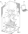
- FIGURE 2 illustrates an example laser system 200 for cleaning nutplates, according to a particular embodiment.
- laser system 200 cleans a faying surface of nutplates, such as faying surface 108, to prepare nutplates before attaching them to a surface, e.g., surface 112 of FIGURE 1 .
- laser system 200 may clean or otherwise remove contaminants from a faying surface of nutplate, which may be referred to as laser ablation, such that an adhesive can be placed on the cleaned faying surface and more readily or strongly bond to the faying surface.
- laser system 200 contains a container 202 with a door 204, where inside container 202 a nutplate tray 206 holding nutplates 102 rests on a conveyor 208, and a laser 210 having a lens 212 faces nutplates 102 at a distance 214 from nutplates 102.
- laser system 200 contains a controller 216 and a terminal 218.
- Container 202 generally contains some or all of the components of laser system 200 (also referred to as a nutplate laser cleaning system) and, in certain embodiments, protects operators of system 200 from potentially harmful exposure to laser 210.
- Container 202 can be made of any suitable material, such as metal, polymer, glass, etc. and may be opaque, transparent, semi-transparent, or any combination thereof.
- Container 202 in some embodiments has a door 204, wherein door 204 provides access to the inside of container 202 (e.g., allows for nutplates to be placed in container 202 or removed from container 202) and increases the safety of laser system 200 by protecting operators from laser 210 when door 204 is closed.
- Door 204 can be made of any suitable material, such as metal, polymer, glass, etc. and may be opaque, transparent, semi-transparent, or any combination of thereof.
- container 202 may contain or connect to a vacuum system that creates a complete or partial vacuum (or otherwise reduces the pressure) in container 202.
- a vacuum system may remove air, dust, and other matter that can settle on nutplates 102, scatter or otherwise interfere with laser 210, or chemically react with the faying surfaces during cleaning.
- Nutplate tray 206 generally holds nutplates 102 during the laser cleaning process.
- nutplate tray 206 is configured to hold nutplates of a specific shape.
- Nutplate tray 206 may be customized for particular nutplate type(s)/shape(s), or contain different customized inserts for different nutplate types/shapes, e.g., in order to hold nutplates 102 steady and such that faying surface 108 is a particular distance from laser 210 or laser lens 212.
- nutplate tray 206 may be able to hold 16 nutplates of one or more shapes or styles (e.g., open style or dome) in a four by four arrangement.
- Nutplate tray 206 may also, in some embodiments, allow for worm 110 and nut 104 of nutplate 102 to extend below nutplate tray 206.
- nutplate tray 206 is configured to hold nutplates such that the faying surfaces 108 of the nutplates 102 are facing (oriented) toward laser 210.
- nutplate tray 206 may hold faying surfaces 108 of nutplates 102 at a particular distance 214 (e.g., a focal distance of lens 212) from laser lens 212, such that, for example, laser 210 (or a laser beam generated by laser 210) is at its maximum intensity for a given output while using lens 212 (or within 1%, 2%, 5%, 10%, 25%, 50%, etc. of its maximum intensity) at the distance between laser lens 212 and faying surfaces 108.
- Nutplate trays 206 of different heights may be used to change distance 214 in certain embodiments, such as to get closer to the focal distance of lens 212.
- Nutplate tray 206 may be made out of any suitable material such as metal, polymer, etc. and may be made by any suitable means such as dynamically being created by a 3D printer in response to a new batch of nutplates arriving or being scheduled to arrive.
- nutplate tray 206 may be configured to hold nutplates 102 such that each faying surface of nutplates 102 is oriented such that a laser beam produced by laser 210 is capable of contacting each faying surface at least once during a cleaning cycle.
- a cleaning cycle may contain any number of movements of any number of components of laser system 200, such as multiple passes of laser 210 created by laser 210 moving and/or nutplate tray 206 moving (e.g., via conveyor 208) such that laser 210 cleans multiple nutplates.
- Conveyor 208 generally moves nutplate tray 206 during cleaning to help clean multiple nutplates 102.
- conveyor 208 moves nutplate tray 206 in one or more directions such that a laser beam from laser 210 makes contact with and cleans multiple (or all) faying surfaces 108 of nutplates 102 in nutplate tray 206.
- conveyor 208 translates nutplate 206 in the X and Y directions (2D) such that the distance 214 between faying surface 108 and lens 212 (e.g., a focal distance of lens 212) is constant for multiple nutplates 102, which may increase the consistency and effectiveness of cleaning nutplates 102.
- conveyor 208 may move nutplate tray 206 in the Z direction or in no direction. Conveyor 208, in some embodiments, may move nutplate tray 206 according to instructions from controller 216. While conveyor 208 moves nutplate tray 206 (or remains stationary), laser 210 may be stationary or may be moving in the X, Y, or Z direction.
- Laser 210 generally produces a laser (also described as a laser beam) directed towards nutplates 102, particularly faying surfaces 108.
- the laser beam produced by laser 210 impacts faying surface 108 in certain embodiments and removes some or all contaminants from faying surface 210.
- the process of cleaning nutplate faying surfaces 108 with a laser may be referred to as a form of laser ablation.
- laser 210 produces a laser beam that is orthogonal to faying surface 108 or any suitable angle to faying surface 108.
- Laser 210 may also make multiple passes (e.g., by laser 210 moving, nutplate tray 206 moving, or both) at the same nutplate at the same or different angles.
- FIGURE 3 describes example embodiments where multiple passes of laser 210 occur at different angles.
- laser 210 is a Nd:YAG (neodymium-doped yttrium aluminum garnet) class 1 or class 4 laser producing a laser beam with a wavelength of 1064 nm (nanometers), though any suitable laser of any type, class, or wavelength can be used to clean nutplates 102 (e.g., faying surface 108).
- a suitable laser beam may have a wavelength of between 100 nm and 7,000 nm, 500 nm and 3,000 nm, 800 nm and 2000 nm, 1000 nm and 1200 nm, 1000 nm and 1100 nm, 1050 nm and 1075 nm, or any other suitable range.
- a laser beam produced by laser 210 may be any suitable type of laser beam.
- the laser beam may be a pulse laser.
- Certain embodiments of the present disclosure contemplate using or modifying characteristics of laser beams produced by laser 210, such as mark speed (how fast the laser moves back and forth across an area), angle, intensity, beam width, pulse frequency, etc.
- controller 216 controls some or all laser characteristics, automatically or based on user input. In other embodiments, laser characteristics or laser position may be manipulated manually.
- laser 210 can move in space relative to nutplates 102 and nutplate tray 206.
- laser 210 may be able to move in the X, Y, Z, or any combination of these directions.
- laser 210 may tilt at any angle.
- the movement of laser 210 is controlled by controller 216.
- Laser 210 may move across nutplate tray 206 (which may include tilting) at one or more angles and one or more times (passes) in certain embodiments.
- Laser 210 may be pointed down at faying surfaces 108, but any orientation of laser 210 and faying surfaces 108 are contemplated, e.g., where laser 210 is pointed in the Y direction toward a nutplate tray that is mounted on the X-Z plane of FIGURE 2 . All other components of laser system 200 may be moved in relation to one another to accommodate any suitable setup.
- Lens 212 generally focuses a laser beam emitted from laser 210.
- lens 212 has a focal distance, such that at the focal distance away from lens 212 a laser beam generated by laser 210 passing through the lens will have maximum intensity (energy per unit area) for any given power output from laser 210.
- a faying surface 108 that is a focal distance away from lens 212 (where distance 214 equals a focal distance of lens 212) will therefore encounter a laser beam produced by laser 210 at its maximum intensity in certain embodiments.
- distance 214 may be at such a focal distance or within 1%, 2%, 5%, 10%, 25%, 50%, etc. of the focal distance.
- Lens 212 is connected to laser 210 in certain embodiments, for example by threading onto laser 210. Different lenses may have different focal distances. In one example, a 330 mm lens may be used, though any suitable lens of any suitable size (e.g., between 100 mm and 1000 mm, 200 mm and 500 mm, 300 mm and 400 mm, etc.) may be used.
- Distance 214 is generally the distance between lens 212 and a faying surface 108 that is in contact with a laser beam produced by laser 210. Put another way, distance 214 is generally the distance between (1) a point where a laser beam from laser 210 contacts a surface (e.g., faying surface 108) and (2) lens 212. In particular embodiments, distance 214 is selected to provide sufficient or optimal cleaning of a faying surface 108. In certain embodiments, distance 214 may be equal to the focal distance of lens 212, and at such a distance 214 a laser beam passing through lens 212 is at its maximum intensity. Distance 214 may be any suitable distance, for example within 1%, 2%, 5%, 10%, 25%, 50%, etc. of the focal distance of lens 212. Distance 214 may change over time, and the placement of laser 210 and nutplate tray 206, the height of nutplate tray 206, and the position of conveyor 208 may affect distance 214.
- Controller 216 generally controls some or all of the components of laser system 200.
- controller 216 may control the position (including the angle) of laser 210, the position of conveyor 208 (and nutplate tray 206), the speed of laser 210 and/or conveyor 208, the pattern of movement of laser 210 and/or conveyor 208, characteristics of laser beams produced by laser 210, or any other component of laser system 200.
- Controller 216 may contain a processor and/or memory of any suitable type, including any kind of non-transient computer readable medium. Such processor and memory resources may be located locally within controller 216, within other components of laser system 200, or external to laser system 200 as a network resource (e.g., a private network, public network, or cloud computing resource).
- Controller 216 may also contain software (e.g., a program) for controlling components of laser system 200. Such software may be installed, modified, operated, or interacted with via terminal 218 or via a network.
- Terminal 218 generally acts as an input/output device for controller 216.
- terminal 218 may contain a display screen and a keyboard that allows a user to see the status of laser system 200 and enter commands to laser system 200.
- terminal 218 can be used to control or operate controller 216.
- Terminal 218, in particular embodiments, may be a computer, such as a laptop, desktop, tablet, server, PDA, smartphone, or any other suitable device.
- terminal 218 may contain some or all of the processor and memory resources used by controller 216.
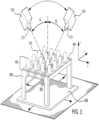
- FIGURE 3 illustrates an example of certain components of laser system 200 of FIGURE 2 while conducting multiple passes to clean nutplates 102, according to a particular embodiment. More specifically, FIGURE 3 illustrates laser 210 conducting two passes across a nutplate at angles ⁇ 1 and ⁇ 2.
- Nutplates 102 are shown in this example embodiment as being held by nutplate tray 206 resting on conveyor 208. Nutplates 102 have faying surfaces 108 that are in the process of being cleaned by laser 210 having lens 212.
- Laser 210 is making two passes, the first at a first position having angle ⁇ 1 and the second at a second position having angle ⁇ 2.
- a single pass at any position having any angle could produce a shadow effect, where, e.g., worm 110 comes between a laser beam produced by laser 210 and faying surface 108, which produces an area that is not cleaned by laser 210 (a shadow area 302).
- laser 210 can make multiple passes over faying surface 108 at different positions (e.g. at ⁇ 1 and ⁇ 2), such that more or all of faying surface 108 is cleaned at least once by laser 210 than if just one pass were completed.
- Such multiple passes at different positions, e.g., having different angles may reduce or eliminate the shadow effect and shadow area 302.
- Angles ⁇ 1 and ⁇ 2 may describe angles measures relative to any suitable axis, such as the X, Y, or Z axes as shown in FIGURE 3 , and in any suitable plane.
- ⁇ 1 and ⁇ 2 are measured from the Z axis (orthogonal to faying surfaces 108 and located where the laser beam meets the faying surface) along the Z-Y plane.
- Angles ⁇ 1 and ⁇ 2 may be any suitable angle, including 0°, and may change over time during a particular pass of between particular passes.
- the laser system of FIGURE 2 may conduct a cleaning cycle, e.g., containing one or more passes of laser 210 across faying surfaces 108 of nutplates 102 held by nutplate tray 206.
- nutplate tray 206 holds nutplates 102 such that a faying surface of each nutplate 102 is accessible by a laser beam produced by laser 210 for cleaning at least once during the cleaning cycle, whether on the same pass of laser 210 or one different passes of laser 210 during the cleaning cycle.
- FIGURE 3 describes particular embodiments, any number of passes of laser 210 (or multiple lasers) having any position, including any angle, are contemplated.
- laser system 200 may be used to clean faying surfaces of any other appropriate part (e.g., small parts with surfaces that are typically abrasively cleaned).
- some embodiments of laser system 200 may be used to clean parts such as radius blocks, shims, click bond studs, brackets, and the like.
- tray 206 may be customized for the shape of the particular parts in order to hold the parts steady during cleaning and such that faying surfaces of the parts are a particular distance from laser 210 or laser lens 212.
Landscapes
- Engineering & Computer Science (AREA)
- Physics & Mathematics (AREA)
- Optics & Photonics (AREA)
- Mechanical Engineering (AREA)
- Plasma & Fusion (AREA)
- General Engineering & Computer Science (AREA)
- Chemical & Material Sciences (AREA)
- Composite Materials (AREA)
- Laser Beam Processing (AREA)
- Cleaning In General (AREA)
Applications Claiming Priority (1)
| Application Number | Priority Date | Filing Date | Title |
|---|---|---|---|
| US15/631,001 US10737303B2 (en) | 2017-06-23 | 2017-06-23 | Nutplate preparation laser system |
Publications (2)
| Publication Number | Publication Date |
|---|---|
| EP3417953A1 EP3417953A1 (en) | 2018-12-26 |
| EP3417953B1 true EP3417953B1 (en) | 2023-11-01 |
Family
ID=62165392
Family Applications (1)
| Application Number | Title | Priority Date | Filing Date |
|---|---|---|---|
| EP18171999.8A Active EP3417953B1 (en) | 2017-06-23 | 2018-05-14 | Nutplate preparation laser system |
Country Status (3)
| Country | Link |
|---|---|
| US (2) | US10737303B2 (https=) |
| EP (1) | EP3417953B1 (https=) |
| JP (1) | JP6938430B2 (https=) |
Families Citing this family (3)
| Publication number | Priority date | Publication date | Assignee | Title |
|---|---|---|---|---|
| US11173526B2 (en) | 2019-11-27 | 2021-11-16 | Lockheed Martin Corporation | Automated structural laser cleaning system |
| GB2592416B (en) * | 2020-02-27 | 2022-08-03 | Douwe Egberts Bv | Improvements in or relating to capsule filling lines |
| US20240367204A1 (en) * | 2023-05-03 | 2024-11-07 | Lockheed Martin Corporation | Automated Pre-Weld Tube Cleaning Using Laser Ablation |
Family Cites Families (24)
| Publication number | Priority date | Publication date | Assignee | Title |
|---|---|---|---|---|
| JPS5935892A (ja) | 1982-08-20 | 1984-02-27 | Nec Corp | レ−ザ加工装置 |
| BR8606732A (pt) | 1985-06-18 | 1987-08-11 | Dow Chemical Co | Metodo para produzir adesoes aperfeicoadas entre superficies e artigos produzidos pelo metodo |
| US4861407A (en) | 1985-06-18 | 1989-08-29 | The Dow Chemical Company | Method for adhesive bonding articles via pretreatment with energy beams |
| US4898650A (en) | 1988-05-10 | 1990-02-06 | Amp Incorporated | Laser cleaning of metal stock |
| US5013391A (en) | 1989-06-12 | 1991-05-07 | Physical Systems, Inc. | Adhesive nutplate assembly for mounting |
| FR2727780B1 (fr) | 1994-12-01 | 1997-01-10 | Solaic Sa | Procede et installation pour traiter en surface une bande de matiere plastique portant des modules pour cartes electroniques |
| US5780806A (en) | 1995-07-25 | 1998-07-14 | Lockheed Idaho Technologies Company | Laser ablation system, and method of decontaminating surfaces |
| WO1998003600A1 (en) | 1996-07-23 | 1998-01-29 | Ciba Specialty Chemicals Holding Inc. | Metal surface treatment |
| US6573702B2 (en) * | 1997-09-12 | 2003-06-03 | New Wave Research | Method and apparatus for cleaning electronic test contacts |
| SG84519A1 (en) * | 1998-12-07 | 2001-11-20 | Advanced Systems Automation | Method and apparatus for removal of mold flash |
| JP2002045812A (ja) * | 2000-07-31 | 2002-02-12 | Sharp Corp | クリーニング装置およびクリーニング方法 |
| FR2830209B1 (fr) | 2001-09-28 | 2004-01-16 | Hutchinson | Procede de fabrication d'un dispositif antivibratoire pour automobile comportant un insert metallique destine a etre adherise avec un elastomere |
| US6750421B2 (en) * | 2002-02-19 | 2004-06-15 | Gsi Lumonics Ltd. | Method and system for laser welding |
| EP1598121A3 (de) | 2004-05-18 | 2007-02-14 | Airbus Deutschland GmbH | Lasergestütztes Entschichtungsverfahren |
| KR100639436B1 (ko) * | 2005-08-30 | 2006-10-27 | 주식회사 나인벨 | 번인소켓 세정장치 |
| US8536483B2 (en) | 2007-03-22 | 2013-09-17 | General Lasertronics Corporation | Methods for stripping and modifying surfaces with laser-induced ablation |
| US8740152B1 (en) | 2008-05-01 | 2014-06-03 | Textron Innovations, Inc. | Rivetless nutplates for aircraft |
| SG11201405364UA (en) * | 2012-03-21 | 2014-10-30 | Ngee Ann Polytechnic | A laser cleaning apparatus and method |
| US10407821B2 (en) * | 2012-07-10 | 2019-09-10 | Woodrow Scientific Ltd. | Methods and apparatus for laser cleaning |
| AT513222B1 (de) | 2012-08-03 | 2016-11-15 | Haas Food Equipment Gmbh | Verfahren und Vorrichtung zur Reinigung von Backoberflächen |
| GB2511036B (en) * | 2013-02-15 | 2015-12-16 | Rolls Royce Plc | Process and Apparatus for Cleaning a Surface |
| US9919502B2 (en) | 2014-04-23 | 2018-03-20 | Schaublin Sa | Method and apparatus for preparing a surface for bonding a material thereto |
| PL3180823T3 (pl) | 2014-08-13 | 2022-08-08 | Ipg Photonics Corporation | System, sposób i zastosowanie wielowiązkowego lasera światłowodowego |
| US9764383B2 (en) | 2014-10-02 | 2017-09-19 | Continental Automotive Systems, Inc. | Laser trimming surface cleaning for adhesion to cast metals |
-
2017
- 2017-06-23 US US15/631,001 patent/US10737303B2/en active Active
-
2018
- 2018-05-14 EP EP18171999.8A patent/EP3417953B1/en active Active
- 2018-06-13 JP JP2018112727A patent/JP6938430B2/ja active Active
-
2020
- 2020-08-11 US US16/990,646 patent/US20200368791A1/en not_active Abandoned
Also Published As
| Publication number | Publication date |
|---|---|
| JP2019005743A (ja) | 2019-01-17 |
| US20200368791A1 (en) | 2020-11-26 |
| JP6938430B2 (ja) | 2021-09-22 |
| US10737303B2 (en) | 2020-08-11 |
| EP3417953A1 (en) | 2018-12-26 |
| US20180369879A1 (en) | 2018-12-27 |
Similar Documents
| Publication | Publication Date | Title |
|---|---|---|
| US20200368791A1 (en) | Nutplate Preparation Laser System | |
| TWI892641B (zh) | 光學系統 | |
| EP3476519B1 (en) | Optimized-coverage selective laser ablation system and method | |
| CN106853554B (zh) | 智能型激光加工系统及其加工方法 | |
| TWI440199B (zh) | 塗佈薄膜之平坦基板表面邊緣部份薄膜的燒蝕方法及裝置 | |
| JP7325897B2 (ja) | 加工装置及び被加工物の加工方法 | |
| US20230061635A1 (en) | Laser processing apparatus facilitating directed inspection of laser-processed workpieces and methods of operating the same | |
| CN208195936U (zh) | 一种激光去涂层过程同轴监测装置 | |
| JP2022536649A (ja) | レーザ加工装置、これを動作させる方法、及びこれを用いてワークピースを加工する方法 | |
| CN103597569A (zh) | 用于至少部分地解构平面显示屏幕的方法 | |
| JP2015147265A (ja) | 組み立て装置 | |
| CA2988370A1 (en) | Assembly body manufacturing device and assembly body manufacturing method | |
| JPWO2016001992A1 (ja) | 薄板状部材の接合装置および薄板状部材の接合方法 | |
| EP4452549A1 (en) | Method and apparatus for cutting and removing parts | |
| WO2019003596A1 (ja) | レーザ加工機 | |
| KR101326398B1 (ko) | 피가공물 적재 고정용 테이블 및 피가공물 적재 고정용 글래스 척 | |
| JP5286885B2 (ja) | 観察装置およびレーザー加工装置 | |
| JP2000225485A (ja) | レーザ加工装置のステージ | |
| JP2024502043A (ja) | レーザ加工装置、これを動作させる方法、及びこれを用いてワークピースを加工する方法 | |
| CN118321857B (zh) | 利用自动换刀系统的废显示器拆解自动化控制系统 | |
| CN211247615U (zh) | 激光清洗装置 | |
| KR20180115223A (ko) | 프레임 유닛 및 피가공물의 레이저 가공 방법 | |
| KR101490322B1 (ko) | 레이저를 이용한 기판 챔퍼링 장치 | |
| KR102177675B1 (ko) | 분할 공구 및 분할 공구의 사용 방법 | |
| Bluemel et al. | Robot based remote laser cutting of three-dimensional automotive composite parts with thicknesses up to 5mm |
Legal Events
| Date | Code | Title | Description |
|---|---|---|---|
| PUAI | Public reference made under article 153(3) epc to a published international application that has entered the european phase |
Free format text: ORIGINAL CODE: 0009012 |
|
| STAA | Information on the status of an ep patent application or granted ep patent |
Free format text: STATUS: THE APPLICATION HAS BEEN PUBLISHED |
|
| AK | Designated contracting states |
Kind code of ref document: A1 Designated state(s): AL AT BE BG CH CY CZ DE DK EE ES FI FR GB GR HR HU IE IS IT LI LT LU LV MC MK MT NL NO PL PT RO RS SE SI SK SM TR |
|
| AX | Request for extension of the european patent |
Extension state: BA ME |
|
| STAA | Information on the status of an ep patent application or granted ep patent |
Free format text: STATUS: REQUEST FOR EXAMINATION WAS MADE |
|
| 17P | Request for examination filed |
Effective date: 20190626 |
|
| RBV | Designated contracting states (corrected) |
Designated state(s): AL AT BE BG CH CY CZ DE DK EE ES FI FR GB GR HR HU IE IS IT LI LT LU LV MC MK MT NL NO PL PT RO RS SE SI SK SM TR |
|
| STAA | Information on the status of an ep patent application or granted ep patent |
Free format text: STATUS: EXAMINATION IS IN PROGRESS |
|
| 17Q | First examination report despatched |
Effective date: 20211220 |
|
| GRAP | Despatch of communication of intention to grant a patent |
Free format text: ORIGINAL CODE: EPIDOSNIGR1 |
|
| STAA | Information on the status of an ep patent application or granted ep patent |
Free format text: STATUS: GRANT OF PATENT IS INTENDED |
|
| INTG | Intention to grant announced |
Effective date: 20230621 |
|
| GRAS | Grant fee paid |
Free format text: ORIGINAL CODE: EPIDOSNIGR3 |
|
| GRAA | (expected) grant |
Free format text: ORIGINAL CODE: 0009210 |
|
| STAA | Information on the status of an ep patent application or granted ep patent |
Free format text: STATUS: THE PATENT HAS BEEN GRANTED |
|
| AK | Designated contracting states |
Kind code of ref document: B1 Designated state(s): AL AT BE BG CH CY CZ DE DK EE ES FI FR GB GR HR HU IE IS IT LI LT LU LV MC MK MT NL NO PL PT RO RS SE SI SK SM TR |
|
| REG | Reference to a national code |
Ref country code: GB Ref legal event code: FG4D |
|
| REG | Reference to a national code |
Ref country code: CH Ref legal event code: EP |
|
| REG | Reference to a national code |
Ref country code: DE Ref legal event code: R096 Ref document number: 602018060265 Country of ref document: DE |
|
| REG | Reference to a national code |
Ref country code: IE Ref legal event code: FG4D |
|
| P01 | Opt-out of the competence of the unified patent court (upc) registered |
Effective date: 20231101 |
|
| REG | Reference to a national code |
Ref country code: LT Ref legal event code: MG9D |
|
| REG | Reference to a national code |
Ref country code: NL Ref legal event code: MP Effective date: 20231101 |
|
| PG25 | Lapsed in a contracting state [announced via postgrant information from national office to epo] |
Ref country code: GR Free format text: LAPSE BECAUSE OF FAILURE TO SUBMIT A TRANSLATION OF THE DESCRIPTION OR TO PAY THE FEE WITHIN THE PRESCRIBED TIME-LIMIT Effective date: 20240202 |
|
| PG25 | Lapsed in a contracting state [announced via postgrant information from national office to epo] |
Ref country code: IS Free format text: LAPSE BECAUSE OF FAILURE TO SUBMIT A TRANSLATION OF THE DESCRIPTION OR TO PAY THE FEE WITHIN THE PRESCRIBED TIME-LIMIT Effective date: 20240301 |
|
| PG25 | Lapsed in a contracting state [announced via postgrant information from national office to epo] |
Ref country code: LT Free format text: LAPSE BECAUSE OF FAILURE TO SUBMIT A TRANSLATION OF THE DESCRIPTION OR TO PAY THE FEE WITHIN THE PRESCRIBED TIME-LIMIT Effective date: 20231101 |
|
| REG | Reference to a national code |
Ref country code: AT Ref legal event code: MK05 Ref document number: 1626611 Country of ref document: AT Kind code of ref document: T Effective date: 20231101 |
|
| PG25 | Lapsed in a contracting state [announced via postgrant information from national office to epo] |
Ref country code: NL Free format text: LAPSE BECAUSE OF FAILURE TO SUBMIT A TRANSLATION OF THE DESCRIPTION OR TO PAY THE FEE WITHIN THE PRESCRIBED TIME-LIMIT Effective date: 20231101 |
|
| PG25 | Lapsed in a contracting state [announced via postgrant information from national office to epo] |
Ref country code: AT Free format text: LAPSE BECAUSE OF FAILURE TO SUBMIT A TRANSLATION OF THE DESCRIPTION OR TO PAY THE FEE WITHIN THE PRESCRIBED TIME-LIMIT Effective date: 20231101 |
|
| PG25 | Lapsed in a contracting state [announced via postgrant information from national office to epo] |
Ref country code: ES Free format text: LAPSE BECAUSE OF FAILURE TO SUBMIT A TRANSLATION OF THE DESCRIPTION OR TO PAY THE FEE WITHIN THE PRESCRIBED TIME-LIMIT Effective date: 20231101 |
|
| PG25 | Lapsed in a contracting state [announced via postgrant information from national office to epo] |
Ref country code: NL Free format text: LAPSE BECAUSE OF FAILURE TO SUBMIT A TRANSLATION OF THE DESCRIPTION OR TO PAY THE FEE WITHIN THE PRESCRIBED TIME-LIMIT Effective date: 20231101 Ref country code: LT Free format text: LAPSE BECAUSE OF FAILURE TO SUBMIT A TRANSLATION OF THE DESCRIPTION OR TO PAY THE FEE WITHIN THE PRESCRIBED TIME-LIMIT Effective date: 20231101 Ref country code: IS Free format text: LAPSE BECAUSE OF FAILURE TO SUBMIT A TRANSLATION OF THE DESCRIPTION OR TO PAY THE FEE WITHIN THE PRESCRIBED TIME-LIMIT Effective date: 20240301 Ref country code: GR Free format text: LAPSE BECAUSE OF FAILURE TO SUBMIT A TRANSLATION OF THE DESCRIPTION OR TO PAY THE FEE WITHIN THE PRESCRIBED TIME-LIMIT Effective date: 20240202 Ref country code: ES Free format text: LAPSE BECAUSE OF FAILURE TO SUBMIT A TRANSLATION OF THE DESCRIPTION OR TO PAY THE FEE WITHIN THE PRESCRIBED TIME-LIMIT Effective date: 20231101 Ref country code: BG Free format text: LAPSE BECAUSE OF FAILURE TO SUBMIT A TRANSLATION OF THE DESCRIPTION OR TO PAY THE FEE WITHIN THE PRESCRIBED TIME-LIMIT Effective date: 20240201 Ref country code: AT Free format text: LAPSE BECAUSE OF FAILURE TO SUBMIT A TRANSLATION OF THE DESCRIPTION OR TO PAY THE FEE WITHIN THE PRESCRIBED TIME-LIMIT Effective date: 20231101 Ref country code: PT Free format text: LAPSE BECAUSE OF FAILURE TO SUBMIT A TRANSLATION OF THE DESCRIPTION OR TO PAY THE FEE WITHIN THE PRESCRIBED TIME-LIMIT Effective date: 20240301 |
|
| PG25 | Lapsed in a contracting state [announced via postgrant information from national office to epo] |
Ref country code: SE Free format text: LAPSE BECAUSE OF FAILURE TO SUBMIT A TRANSLATION OF THE DESCRIPTION OR TO PAY THE FEE WITHIN THE PRESCRIBED TIME-LIMIT Effective date: 20231101 Ref country code: RS Free format text: LAPSE BECAUSE OF FAILURE TO SUBMIT A TRANSLATION OF THE DESCRIPTION OR TO PAY THE FEE WITHIN THE PRESCRIBED TIME-LIMIT Effective date: 20231101 Ref country code: PL Free format text: LAPSE BECAUSE OF FAILURE TO SUBMIT A TRANSLATION OF THE DESCRIPTION OR TO PAY THE FEE WITHIN THE PRESCRIBED TIME-LIMIT Effective date: 20231101 Ref country code: NO Free format text: LAPSE BECAUSE OF FAILURE TO SUBMIT A TRANSLATION OF THE DESCRIPTION OR TO PAY THE FEE WITHIN THE PRESCRIBED TIME-LIMIT Effective date: 20240201 Ref country code: LV Free format text: LAPSE BECAUSE OF FAILURE TO SUBMIT A TRANSLATION OF THE DESCRIPTION OR TO PAY THE FEE WITHIN THE PRESCRIBED TIME-LIMIT Effective date: 20231101 Ref country code: HR Free format text: LAPSE BECAUSE OF FAILURE TO SUBMIT A TRANSLATION OF THE DESCRIPTION OR TO PAY THE FEE WITHIN THE PRESCRIBED TIME-LIMIT Effective date: 20231101 |
|
| PG25 | Lapsed in a contracting state [announced via postgrant information from national office to epo] |
Ref country code: DK Free format text: LAPSE BECAUSE OF FAILURE TO SUBMIT A TRANSLATION OF THE DESCRIPTION OR TO PAY THE FEE WITHIN THE PRESCRIBED TIME-LIMIT Effective date: 20231101 |
|
| PG25 | Lapsed in a contracting state [announced via postgrant information from national office to epo] |
Ref country code: CZ Free format text: LAPSE BECAUSE OF FAILURE TO SUBMIT A TRANSLATION OF THE DESCRIPTION OR TO PAY THE FEE WITHIN THE PRESCRIBED TIME-LIMIT Effective date: 20231101 |
|
| PG25 | Lapsed in a contracting state [announced via postgrant information from national office to epo] |
Ref country code: SK Free format text: LAPSE BECAUSE OF FAILURE TO SUBMIT A TRANSLATION OF THE DESCRIPTION OR TO PAY THE FEE WITHIN THE PRESCRIBED TIME-LIMIT Effective date: 20231101 |
|
| PG25 | Lapsed in a contracting state [announced via postgrant information from national office to epo] |
Ref country code: SM Free format text: LAPSE BECAUSE OF FAILURE TO SUBMIT A TRANSLATION OF THE DESCRIPTION OR TO PAY THE FEE WITHIN THE PRESCRIBED TIME-LIMIT Effective date: 20231101 Ref country code: SK Free format text: LAPSE BECAUSE OF FAILURE TO SUBMIT A TRANSLATION OF THE DESCRIPTION OR TO PAY THE FEE WITHIN THE PRESCRIBED TIME-LIMIT Effective date: 20231101 Ref country code: EE Free format text: LAPSE BECAUSE OF FAILURE TO SUBMIT A TRANSLATION OF THE DESCRIPTION OR TO PAY THE FEE WITHIN THE PRESCRIBED TIME-LIMIT Effective date: 20231101 Ref country code: DK Free format text: LAPSE BECAUSE OF FAILURE TO SUBMIT A TRANSLATION OF THE DESCRIPTION OR TO PAY THE FEE WITHIN THE PRESCRIBED TIME-LIMIT Effective date: 20231101 Ref country code: CZ Free format text: LAPSE BECAUSE OF FAILURE TO SUBMIT A TRANSLATION OF THE DESCRIPTION OR TO PAY THE FEE WITHIN THE PRESCRIBED TIME-LIMIT Effective date: 20231101 |
|
| REG | Reference to a national code |
Ref country code: DE Ref legal event code: R097 Ref document number: 602018060265 Country of ref document: DE |
|
| PLBE | No opposition filed within time limit |
Free format text: ORIGINAL CODE: 0009261 |
|
| STAA | Information on the status of an ep patent application or granted ep patent |
Free format text: STATUS: NO OPPOSITION FILED WITHIN TIME LIMIT |
|
| 26N | No opposition filed |
Effective date: 20240802 |
|
| PG25 | Lapsed in a contracting state [announced via postgrant information from national office to epo] |
Ref country code: SI Free format text: LAPSE BECAUSE OF FAILURE TO SUBMIT A TRANSLATION OF THE DESCRIPTION OR TO PAY THE FEE WITHIN THE PRESCRIBED TIME-LIMIT Effective date: 20231101 |
|
| PG25 | Lapsed in a contracting state [announced via postgrant information from national office to epo] |
Ref country code: SI Free format text: LAPSE BECAUSE OF FAILURE TO SUBMIT A TRANSLATION OF THE DESCRIPTION OR TO PAY THE FEE WITHIN THE PRESCRIBED TIME-LIMIT Effective date: 20231101 |
|
| REG | Reference to a national code |
Ref country code: CH Ref legal event code: PL |
|
| PG25 | Lapsed in a contracting state [announced via postgrant information from national office to epo] |
Ref country code: MC Free format text: LAPSE BECAUSE OF FAILURE TO SUBMIT A TRANSLATION OF THE DESCRIPTION OR TO PAY THE FEE WITHIN THE PRESCRIBED TIME-LIMIT Effective date: 20231101 |
|
| PG25 | Lapsed in a contracting state [announced via postgrant information from national office to epo] |
Ref country code: LU Free format text: LAPSE BECAUSE OF NON-PAYMENT OF DUE FEES Effective date: 20240514 |
|
| PG25 | Lapsed in a contracting state [announced via postgrant information from national office to epo] |
Ref country code: MC Free format text: LAPSE BECAUSE OF FAILURE TO SUBMIT A TRANSLATION OF THE DESCRIPTION OR TO PAY THE FEE WITHIN THE PRESCRIBED TIME-LIMIT Effective date: 20231101 Ref country code: LU Free format text: LAPSE BECAUSE OF NON-PAYMENT OF DUE FEES Effective date: 20240514 Ref country code: CH Free format text: LAPSE BECAUSE OF NON-PAYMENT OF DUE FEES Effective date: 20240531 |
|
| REG | Reference to a national code |
Ref country code: BE Ref legal event code: MM Effective date: 20240531 |
|
| PG25 | Lapsed in a contracting state [announced via postgrant information from national office to epo] |
Ref country code: IE Free format text: LAPSE BECAUSE OF NON-PAYMENT OF DUE FEES Effective date: 20240514 |
|
| PG25 | Lapsed in a contracting state [announced via postgrant information from national office to epo] |
Ref country code: BE Free format text: LAPSE BECAUSE OF NON-PAYMENT OF DUE FEES Effective date: 20240531 |
|
| PGFP | Annual fee paid to national office [announced via postgrant information from national office to epo] |
Ref country code: DE Payment date: 20250529 Year of fee payment: 8 |
|
| PGFP | Annual fee paid to national office [announced via postgrant information from national office to epo] |
Ref country code: IT Payment date: 20250521 Year of fee payment: 8 |
|
| PGFP | Annual fee paid to national office [announced via postgrant information from national office to epo] |
Ref country code: FR Payment date: 20250526 Year of fee payment: 8 |
|
| PG25 | Lapsed in a contracting state [announced via postgrant information from national office to epo] |
Ref country code: RO Free format text: LAPSE BECAUSE OF FAILURE TO SUBMIT A TRANSLATION OF THE DESCRIPTION OR TO PAY THE FEE WITHIN THE PRESCRIBED TIME-LIMIT Effective date: 20231101 |
|
| PG25 | Lapsed in a contracting state [announced via postgrant information from national office to epo] |
Ref country code: CY Free format text: LAPSE BECAUSE OF FAILURE TO SUBMIT A TRANSLATION OF THE DESCRIPTION OR TO PAY THE FEE WITHIN THE PRESCRIBED TIME-LIMIT; INVALID AB INITIO Effective date: 20180514 |
|
| PG25 | Lapsed in a contracting state [announced via postgrant information from national office to epo] |
Ref country code: HU Free format text: LAPSE BECAUSE OF FAILURE TO SUBMIT A TRANSLATION OF THE DESCRIPTION OR TO PAY THE FEE WITHIN THE PRESCRIBED TIME-LIMIT; INVALID AB INITIO Effective date: 20180514 |
|
| PG25 | Lapsed in a contracting state [announced via postgrant information from national office to epo] |
Ref country code: FI Free format text: LAPSE BECAUSE OF FAILURE TO SUBMIT A TRANSLATION OF THE DESCRIPTION OR TO PAY THE FEE WITHIN THE PRESCRIBED TIME-LIMIT Effective date: 20231101 |
|
| PGFP | Annual fee paid to national office [announced via postgrant information from national office to epo] |
Ref country code: GB Payment date: 20260327 Year of fee payment: 9 |