EP3417505B1 - Bipolarplatte, brennstoffzelle und elektrolyseur - Google Patents
Bipolarplatte, brennstoffzelle und elektrolyseur Download PDFInfo
- Publication number
- EP3417505B1 EP3417505B1 EP17702515.2A EP17702515A EP3417505B1 EP 3417505 B1 EP3417505 B1 EP 3417505B1 EP 17702515 A EP17702515 A EP 17702515A EP 3417505 B1 EP3417505 B1 EP 3417505B1
- Authority
- EP
- European Patent Office
- Prior art keywords
- bipolar plate
- group
- layer
- chemical element
- top layer
- Prior art date
- Legal status (The legal status is an assumption and is not a legal conclusion. Google has not performed a legal analysis and makes no representation as to the accuracy of the status listed.)
- Active
Links
Images
Classifications
-
- H—ELECTRICITY
- H01—ELECTRIC ELEMENTS
- H01M—PROCESSES OR MEANS, e.g. BATTERIES, FOR THE DIRECT CONVERSION OF CHEMICAL ENERGY INTO ELECTRICAL ENERGY
- H01M8/00—Fuel cells; Manufacture thereof
- H01M8/02—Details
- H01M8/0202—Collectors; Separators, e.g. bipolar separators; Interconnectors
- H01M8/0204—Non-porous and characterised by the material
- H01M8/0223—Composites
- H01M8/0228—Composites in the form of layered or coated products
-
- C—CHEMISTRY; METALLURGY
- C23—COATING METALLIC MATERIAL; COATING MATERIAL WITH METALLIC MATERIAL; CHEMICAL SURFACE TREATMENT; DIFFUSION TREATMENT OF METALLIC MATERIAL; COATING BY VACUUM EVAPORATION, BY SPUTTERING, BY ION IMPLANTATION OR BY CHEMICAL VAPOUR DEPOSITION, IN GENERAL; INHIBITING CORROSION OF METALLIC MATERIAL OR INCRUSTATION IN GENERAL
- C23C—COATING METALLIC MATERIAL; COATING MATERIAL WITH METALLIC MATERIAL; SURFACE TREATMENT OF METALLIC MATERIAL BY DIFFUSION INTO THE SURFACE, BY CHEMICAL CONVERSION OR SUBSTITUTION; COATING BY VACUUM EVAPORATION, BY SPUTTERING, BY ION IMPLANTATION OR BY CHEMICAL VAPOUR DEPOSITION, IN GENERAL
- C23C28/00—Coating for obtaining at least two superposed coatings either by methods not provided for in a single one of groups C23C2/00 - C23C26/00 or by combinations of methods provided for in subclasses C23C and C25C or C25D
- C23C28/04—Coating for obtaining at least two superposed coatings either by methods not provided for in a single one of groups C23C2/00 - C23C26/00 or by combinations of methods provided for in subclasses C23C and C25C or C25D only coatings of inorganic non-metallic material
- C23C28/042—Coating for obtaining at least two superposed coatings either by methods not provided for in a single one of groups C23C2/00 - C23C26/00 or by combinations of methods provided for in subclasses C23C and C25C or C25D only coatings of inorganic non-metallic material including a refractory ceramic layer, e.g. refractory metal oxides, ZrO2, rare earth oxides
-
- C—CHEMISTRY; METALLURGY
- C23—COATING METALLIC MATERIAL; COATING MATERIAL WITH METALLIC MATERIAL; CHEMICAL SURFACE TREATMENT; DIFFUSION TREATMENT OF METALLIC MATERIAL; COATING BY VACUUM EVAPORATION, BY SPUTTERING, BY ION IMPLANTATION OR BY CHEMICAL VAPOUR DEPOSITION, IN GENERAL; INHIBITING CORROSION OF METALLIC MATERIAL OR INCRUSTATION IN GENERAL
- C23C—COATING METALLIC MATERIAL; COATING MATERIAL WITH METALLIC MATERIAL; SURFACE TREATMENT OF METALLIC MATERIAL BY DIFFUSION INTO THE SURFACE, BY CHEMICAL CONVERSION OR SUBSTITUTION; COATING BY VACUUM EVAPORATION, BY SPUTTERING, BY ION IMPLANTATION OR BY CHEMICAL VAPOUR DEPOSITION, IN GENERAL
- C23C28/00—Coating for obtaining at least two superposed coatings either by methods not provided for in a single one of groups C23C2/00 - C23C26/00 or by combinations of methods provided for in subclasses C23C and C25C or C25D
- C23C28/30—Coatings combining at least one metallic layer and at least one inorganic non-metallic layer
- C23C28/32—Coatings combining at least one metallic layer and at least one inorganic non-metallic layer including at least one pure metallic layer
- C23C28/321—Coatings combining at least one metallic layer and at least one inorganic non-metallic layer including at least one pure metallic layer with at least one metal alloy layer
-
- C—CHEMISTRY; METALLURGY
- C23—COATING METALLIC MATERIAL; COATING MATERIAL WITH METALLIC MATERIAL; CHEMICAL SURFACE TREATMENT; DIFFUSION TREATMENT OF METALLIC MATERIAL; COATING BY VACUUM EVAPORATION, BY SPUTTERING, BY ION IMPLANTATION OR BY CHEMICAL VAPOUR DEPOSITION, IN GENERAL; INHIBITING CORROSION OF METALLIC MATERIAL OR INCRUSTATION IN GENERAL
- C23C—COATING METALLIC MATERIAL; COATING MATERIAL WITH METALLIC MATERIAL; SURFACE TREATMENT OF METALLIC MATERIAL BY DIFFUSION INTO THE SURFACE, BY CHEMICAL CONVERSION OR SUBSTITUTION; COATING BY VACUUM EVAPORATION, BY SPUTTERING, BY ION IMPLANTATION OR BY CHEMICAL VAPOUR DEPOSITION, IN GENERAL
- C23C28/00—Coating for obtaining at least two superposed coatings either by methods not provided for in a single one of groups C23C2/00 - C23C26/00 or by combinations of methods provided for in subclasses C23C and C25C or C25D
- C23C28/30—Coatings combining at least one metallic layer and at least one inorganic non-metallic layer
- C23C28/34—Coatings combining at least one metallic layer and at least one inorganic non-metallic layer including at least one inorganic non-metallic material layer, e.g. metal carbide, nitride, boride, silicide layer and their mixtures, enamels, phosphates and sulphates
-
- C—CHEMISTRY; METALLURGY
- C23—COATING METALLIC MATERIAL; COATING MATERIAL WITH METALLIC MATERIAL; CHEMICAL SURFACE TREATMENT; DIFFUSION TREATMENT OF METALLIC MATERIAL; COATING BY VACUUM EVAPORATION, BY SPUTTERING, BY ION IMPLANTATION OR BY CHEMICAL VAPOUR DEPOSITION, IN GENERAL; INHIBITING CORROSION OF METALLIC MATERIAL OR INCRUSTATION IN GENERAL
- C23C—COATING METALLIC MATERIAL; COATING MATERIAL WITH METALLIC MATERIAL; SURFACE TREATMENT OF METALLIC MATERIAL BY DIFFUSION INTO THE SURFACE, BY CHEMICAL CONVERSION OR SUBSTITUTION; COATING BY VACUUM EVAPORATION, BY SPUTTERING, BY ION IMPLANTATION OR BY CHEMICAL VAPOUR DEPOSITION, IN GENERAL
- C23C28/00—Coating for obtaining at least two superposed coatings either by methods not provided for in a single one of groups C23C2/00 - C23C26/00 or by combinations of methods provided for in subclasses C23C and C25C or C25D
- C23C28/30—Coatings combining at least one metallic layer and at least one inorganic non-metallic layer
- C23C28/34—Coatings combining at least one metallic layer and at least one inorganic non-metallic layer including at least one inorganic non-metallic material layer, e.g. metal carbide, nitride, boride, silicide layer and their mixtures, enamels, phosphates and sulphates
- C23C28/341—Coatings combining at least one metallic layer and at least one inorganic non-metallic layer including at least one inorganic non-metallic material layer, e.g. metal carbide, nitride, boride, silicide layer and their mixtures, enamels, phosphates and sulphates with at least one carbide layer
-
- C—CHEMISTRY; METALLURGY
- C25—ELECTROLYTIC OR ELECTROPHORETIC PROCESSES; APPARATUS THEREFOR
- C25B—ELECTROLYTIC OR ELECTROPHORETIC PROCESSES FOR THE PRODUCTION OF COMPOUNDS OR NON-METALS; APPARATUS THEREFOR
- C25B9/00—Cells or assemblies of cells; Constructional parts of cells; Assemblies of constructional parts, e.g. electrode-diaphragm assemblies; Process-related cell features
- C25B9/60—Constructional parts of cells
- C25B9/65—Means for supplying current; Electrode connections; Electric inter-cell connections
-
- C—CHEMISTRY; METALLURGY
- C25—ELECTROLYTIC OR ELECTROPHORETIC PROCESSES; APPARATUS THEREFOR
- C25B—ELECTROLYTIC OR ELECTROPHORETIC PROCESSES FOR THE PRODUCTION OF COMPOUNDS OR NON-METALS; APPARATUS THEREFOR
- C25B9/00—Cells or assemblies of cells; Constructional parts of cells; Assemblies of constructional parts, e.g. electrode-diaphragm assemblies; Process-related cell features
- C25B9/70—Assemblies comprising two or more cells
-
- C—CHEMISTRY; METALLURGY
- C25—ELECTROLYTIC OR ELECTROPHORETIC PROCESSES; APPARATUS THEREFOR
- C25B—ELECTROLYTIC OR ELECTROPHORETIC PROCESSES FOR THE PRODUCTION OF COMPOUNDS OR NON-METALS; APPARATUS THEREFOR
- C25B9/00—Cells or assemblies of cells; Constructional parts of cells; Assemblies of constructional parts, e.g. electrode-diaphragm assemblies; Process-related cell features
- C25B9/70—Assemblies comprising two or more cells
- C25B9/73—Assemblies comprising two or more cells of the filter-press type
-
- C—CHEMISTRY; METALLURGY
- C25—ELECTROLYTIC OR ELECTROPHORETIC PROCESSES; APPARATUS THEREFOR
- C25B—ELECTROLYTIC OR ELECTROPHORETIC PROCESSES FOR THE PRODUCTION OF COMPOUNDS OR NON-METALS; APPARATUS THEREFOR
- C25B9/00—Cells or assemblies of cells; Constructional parts of cells; Assemblies of constructional parts, e.g. electrode-diaphragm assemblies; Process-related cell features
- C25B9/70—Assemblies comprising two or more cells
- C25B9/73—Assemblies comprising two or more cells of the filter-press type
- C25B9/75—Assemblies comprising two or more cells of the filter-press type having bipolar electrodes
-
- H—ELECTRICITY
- H01—ELECTRIC ELEMENTS
- H01M—PROCESSES OR MEANS, e.g. BATTERIES, FOR THE DIRECT CONVERSION OF CHEMICAL ENERGY INTO ELECTRICAL ENERGY
- H01M8/00—Fuel cells; Manufacture thereof
- H01M8/02—Details
- H01M8/0202—Collectors; Separators, e.g. bipolar separators; Interconnectors
- H01M8/0204—Non-porous and characterised by the material
- H01M8/0206—Metals or alloys
- H01M8/0208—Alloys
-
- H—ELECTRICITY
- H01—ELECTRIC ELEMENTS
- H01M—PROCESSES OR MEANS, e.g. BATTERIES, FOR THE DIRECT CONVERSION OF CHEMICAL ENERGY INTO ELECTRICAL ENERGY
- H01M8/00—Fuel cells; Manufacture thereof
- H01M8/02—Details
- H01M8/0202—Collectors; Separators, e.g. bipolar separators; Interconnectors
- H01M8/0204—Non-porous and characterised by the material
- H01M8/0206—Metals or alloys
- H01M8/0208—Alloys
- H01M8/021—Alloys based on iron
-
- H—ELECTRICITY
- H01—ELECTRIC ELEMENTS
- H01M—PROCESSES OR MEANS, e.g. BATTERIES, FOR THE DIRECT CONVERSION OF CHEMICAL ENERGY INTO ELECTRICAL ENERGY
- H01M8/00—Fuel cells; Manufacture thereof
- H01M8/02—Details
- H01M8/0202—Collectors; Separators, e.g. bipolar separators; Interconnectors
- H01M8/0204—Non-porous and characterised by the material
- H01M8/0215—Glass; Ceramic materials
-
- H—ELECTRICITY
- H01—ELECTRIC ELEMENTS
- H01M—PROCESSES OR MEANS, e.g. BATTERIES, FOR THE DIRECT CONVERSION OF CHEMICAL ENERGY INTO ELECTRICAL ENERGY
- H01M8/00—Fuel cells; Manufacture thereof
- H01M8/10—Fuel cells with solid electrolytes
- H01M2008/1095—Fuel cells with polymeric electrolytes
-
- Y—GENERAL TAGGING OF NEW TECHNOLOGICAL DEVELOPMENTS; GENERAL TAGGING OF CROSS-SECTIONAL TECHNOLOGIES SPANNING OVER SEVERAL SECTIONS OF THE IPC; TECHNICAL SUBJECTS COVERED BY FORMER USPC CROSS-REFERENCE ART COLLECTIONS [XRACs] AND DIGESTS
- Y02—TECHNOLOGIES OR APPLICATIONS FOR MITIGATION OR ADAPTATION AGAINST CLIMATE CHANGE
- Y02E—REDUCTION OF GREENHOUSE GAS [GHG] EMISSIONS, RELATED TO ENERGY GENERATION, TRANSMISSION OR DISTRIBUTION
- Y02E60/00—Enabling technologies; Technologies with a potential or indirect contribution to GHG emissions mitigation
- Y02E60/30—Hydrogen technology
- Y02E60/50—Fuel cells
Definitions
- the invention relates to a bipolar plate of an energy converter, in particular a fuel cell or an electrolyzer, according to the preamble of patent claim 1.
- the invention further relates to a fuel cell or an electrolyzer with such a bipolar plate.
- Electrochemical systems such as fuel cells, in particular polymer electrolyte fuel cells, and conductive current collecting plates for such fuel cells and electrolyzers as well as current collectors in galvanic cells and electrolyzers are known.
- bipolar or monopolar plates in fuel cells, particularly in oxygen half-cells.
- the bipolar or monopolar plates are made of carbon plates (e.g., graphoil plates), which contain carbon as a key component. These plates tend to be brittle and are comparatively thick, thus significantly reducing the fuel cell's power output.
- Another disadvantage is their lack of physical (e.g., thermomechanical) and/or chemical and/or electrical stability.
- austenitic stainless steels are coated as a carrier with a gold layer in a band range of up to 2 nm.
- This solution has several disadvantages. For example, a gold layer, even one that is only 2 nm thick, is still too expensive for mass applications. A much greater disadvantage can be seen in a basic property of the chemical element gold.
- Gold is more noble than the carrier material than stainless austenitic steel (stainless steel) and therefore causes the carrier to dissolve under unfavorable operating conditions in the fuel cells (e.g. pitting corrosion), which reduces the service life. In environments containing chlorides in particular (e.g. aerosols), corrosion is unavoidable.
- gold is not stable for high-load applications, e.g., at electrolysis conditions above 1500 mV standard hydrogen unit, in both acidic and basic environments.
- nitride or carbide layers on the substrate in the form of so-called hard material coatings based on nitride or carbide.
- nitride which, however, tends to form oxide metal complexes during operation of a fuel cell, even forming closed surface layers. As a result, the surface resistance increases to high values, as is the case with stainless steel.
- Methods for coating with chromium nitride or chromium carbonitride are known, for example, from the patents DE 199 37 255 B4 and EP 1273060 B1 and the disclosure document DE 100 17 200 A1 out.
- the hard coatings exhibit very good operating properties (e.g., resistance to corrosion, abrasion resistance, high contour accuracy), but carry the risk of anodic dissolution if concentration chains form in the fuel cell under unfavorable operating conditions.
- This anodic dissolution occurs when internal electrochemical short circuits occur in the fuel cell, such as the formation of a water film between an active electrode of a membrane electrode assembly of the fuel cell. and the bipolar plate a so-called local element or an unexpected and undesirable reaction element is created.
- dimensionally stable anodes involve the formation of single-phase or multi-phase oxides with ruthenium oxide and/or iridium oxide using refractory metals. While this type of layer is very stable, it results in excessively high electrical resistance. A similar situation occurs when a surface of the substrate, generally made of a precious metal, is doped with iridium.
- the WO 2009 108 102 A1 describes an electrode for an electrochemical cell comprising an electrically conductive substrate with an electrically conductive, corrosion-resistant coating applied thereto, at least in partial areas.
- the coating comprises a multi-element material with a carbide or nitride composition.
- the object of the present invention is to provide an improved bipolar plate generally for an energy converter, in particular for a fuel cell or an electrolyzer. Furthermore, the object of the invention is to provide a fuel cell equipped with such a bipolar plate with an improved layer system and an electrolyzer equipped therewith.
- the object is achieved according to the invention by a bipolar plate of an energy converter, in particular a fuel cell or an electrolyzer, according to claim 1.
- the bipolar plate comprises a metallic substrate and a layer system applied at least in partial areas of the surface of the substrate, wherein the layer system comprises a cover layer and a base layer system.
- the cover layer consists of a homogeneous or heterogeneous solid metallic solution having a metal lattice, which either contains, in a first alternative, a first chemical element from the group of noble metals in the form of iridium as a host metal and, dissolved in the metal lattice of the host metal, further contains at least one further non-metallic chemical element from the group comprising nitrogen, carbon, boron, fluorine, and hydrogen, wherein the at least one non-metallic chemical element is present in the cover layer in a concentration in the range of 0.1 at.% to 65 at.%, or in a second alternative, contains a first chemical element from the group of noble metals in the form of iridium and a second chemical element from the group of noble metals in the form of ruthenium as host metals and contains, dissolved in the metal lattice of the host metal, at least one further non-metallic chemical element from the group comprising nitrogen, carbon, boron, fluorine, hydrogen, wherein the at least one
- a fuel cell in particular a polymer electrolyte fuel cell, comprising at least one bipolar plate according to the invention.
- an electrolyzer comprising at least one bipolar plate according to the invention.
- the top layer is electrically conductive and electrocatalytically active as well as corrosion-protective.
- a homogeneous metallic solution is understood to mean that the non-metallic chemical elements mentioned are dissolved in the metal lattice in such a way that the lattice type of the host metal or host metal alloy does not change substantially.
- the top layer can be metastable or stable in the thermodynamic sense.
- the specific electrical resistance of gold is approximately 10 m ⁇ cm -2 at room temperature.
- the low-valency iridium is thus stabilized to such an extent that the otherwise usual oxidation at approximately 1800 mV in 1 mol/l (1N concentrated) sulfuric acid (H 2 SO 4 ) no longer occurs.
- the measure of stabilization is the gain in free partial mixing energy ⁇ G mixing of the solid solutions or compounds.
- the cover layer preferably has a layer thickness of at least 1 nm to a maximum of 10 nm.
- the top layer preferably further comprises at least one metal from subgroup IV and/or V of the periodic table of chemical elements.
- the advantage of using these metals – either elemental or in the form of compounds – is that they form self-protecting, stable, and conductive layers under corrosion conditions. Form oxides.
- the at least one non-metallic chemical element is present in the cover layer at a concentration in the range of 0.1 at.% to 65 at.%, in particular from 10 to 30 at.%.
- the non-metallic chemical element carbon is present in the cover layer at a concentration range of 10 to 25 at.%.
- the hydrogen or optionally present hydrogen according to the top layer compositions b), c), e) and f) is present only in traces.
- the cover layer can contain at least one chemical element from the group of base metals.
- the at least one chemical element from the group of base metals is preferably aluminum, iron, nickel, cobalt, zinc, cerium, or tin and/or is contained in the cover layer in a concentration range of 0.01 to 5 at.%.
- the cover layer comprises at least one chemical element from the group of refractory metals, in particular titanium and/or zirconium and/or hafnium and/or niobium and/or tantalum. It has been shown that the addition of the refractory metals also partially controls the H2O2 and ozone produced during electrolysis.
- the covering layer is preferably formed as a multinary compound with the addition of refractory metals.
- the cover layer comprising at least one refractory metal, exhibits high conductivity and high corrosion resistance, particularly in a temperature range from 0 to approximately 200 °C.
- multinary solid iridium- and/or ruthenium-containing cover layers provide outstanding properties for long-term use in applications such as fuel cells.
- the particular advantage is that the cover layer, with a density between 10-13 gcm -3, has a density almost half that of a pure precious metal. This allows the use of expensive precious metals and/or their compounds to be reduced, particularly through the formation of multinary compounds with the other elements.
- the at least one chemical element from the group of refractory metals is preferably present in the concentration range of 0.01 to 5 at.% contained in the top layer.
- the at least one chemical element from the group of base metals is present in the form of tin, this and the at least one chemical element from the group of refractory metals are contained together in the top layer in a concentration range of 0.01 to 5 at.%.
- the top layer It has proven effective for the top layer to contain at least one additional chemical element from the group of precious metals in a concentration range of 0.01 to 10 at.%.
- the chemical elements from the group of precious metals are, in particular, platinum, gold, silver, rhodium, and palladium.
- Corrosion protection on metallic substrates is further improved by applying the top layer to the sublayer system formed between the substrate and the top layer. This is particularly advantageous when corrosive ambient media are present, especially when the corrosion media contain chloride.
- the layer system on the bipolar plate includes the top layer and the base layer system.
- the underlayer system comprises at least one underlayer which comprises at least one chemical element from the group titanium, niobium, hafnium, zirconium, tantalum.
- the base layer system has in particular a first base layer in the form of a metallic alloy layer comprising the chemical elements titanium and niobium, in particular 20 - 50 wt.% niobium and the remainder titanium.
- the base layer system has in particular a second base layer comprising at least one chemical element from the group titanium, niobium, zirconium, hafnium, tantalum and furthermore at least one non-metallic element from the group nitrogen, carbon, boron, fluorine.
- the second backing layer is preferably arranged between the first backing layer and the cover layer.
- the second underlayer may further contain up to 5 at.% oxygen.
- a further advantage of choosing a multinary compound for the top layer is that, although it forms oxides under high anodic voltages of up to 3500 mV compared to a standard hydrogen electrode or in the presence of hydrogen peroxide or ozone, these oxides are electrically conductive and self-healing. They tend to form inert and conductive mixed oxide layers with the second base layer.
- the bipolar plate according to the invention comprises the metallic substrate and the layer system applied to at least partial areas of the surface of the substrate.
- the layer system is applied over the entire surface of one or both sides of the plate-shaped substrate.
- the metallic substrate is formed, in particular, from steel or titanium, preferably from stainless steel.
- the thickness of the substrate is preferably less than 1 mm and is in particular equal to 0.5 mm.
- a fuel cell according to the invention in particular a polymer electrolyte fuel cell comprising at least one bipolar plate according to the invention, has proven particularly advantageous in terms of electrical values and corrosion resistance. Such a fuel cell therefore has a long service life of more than 10 years or more than 5,000 vehicle operating hours.
- an electrolyzer which operates on the reverse principle of a fuel cell and uses electrical current to induce a chemical reaction, i.e., a material transformation, comparably long service lives can be achieved.
- the electrolyzer is suitable for hydrogen electrolysis.
- a thickness of the cover layer of less than 10 nm is sufficient to protect against resistance-increasing oxidation of the second base layer.
- the double layer formed by the two-layer structure beneath the cover layer ensures, on the one hand, electrochemical adaptation to a carrier material, i.e., the material from which the carrier is made, and, on the other hand, prevents pore formation due to oxidation and hydrolysis processes.
- the first metallic base layer is preferably made of titanium, niobium, zirconium, tantalum, or hafnium, or alloys of these metals. These are less noble than the steel, particularly stainless steel, substrate material. During corrosion processes, they initially react to form insoluble oxides or voluminous, sometimes gel-like hydroxo compounds of these refractory metals. As a result, the pores close and protect the base material from corrosion. This process represents a self-healing process of the coating system.
- a second underlay layer in the form of a nitride layer serves as a hydrogen barrier and thus protects the substrate, in particular made of stainless steel, of the bipolar plate as well as the metallic first underlay layer from hydrogen embrittlement.
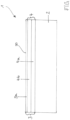
- the figure shows a bipolar plate 1 comprising a substrate 2 made of stainless steel and a layer system 3 applied over the entire surface of one side of the substrate 2.
- the layer system 2 comprises a cover layer 3a and a base layer system 4 comprising a first backing layer 4a and a second backing layer 4b.
- a metallic substrate 2 in the form of a conductor, here for a bipolar plate 1 of a polymer electrolyte fuel cell for the conversion of (reformed) hydrogen is made of a stainless steel, in particular of a so-called authentic steel with very high known requirements regarding corrosion resistance, e.g. with the DIN ISO material number 1.4404.
- a layer system 3 is formed on the substrate 2 of the bipolar plate 1, wherein the substrate 2 is coated in one process pass, first with a first base layer 4a in the form of a 1.5 ⁇ m thick titanium layer, then with a second base layer 4b of approximately the same thickness in the form of a titanium nitride layer, and finally with a cover layer 3a in the form of a 25 nm thick layer.
- the cover layer 3a corresponds to a layer layer that is open on one side, since only one cover layer surface of a further layer, here the second base layer 4b, is designed to contact it.
- the free surface 30 of the cover layer 3a in a fuel cell is arranged directly adjacent to and exposed to an electrolyte, in particular a polymer electrolyte.
- the metallic substrate 2 for the bipolar plate 1 is first coated with a first base layer 4a in the form of a metallic alloy layer with a thickness of several hundred nm, the metallic alloy layer having the composition Ti 0.9 Nb 0.1 . Subsequently, a second base layer 4b with a thickness of another several hundred nm and the composition Ti 0.9 Nb 0.1 N 1-x is applied. A cover layer 3a with a thickness of several nm is applied thereon.
- the advantage is an exceptionally high stability against oxidation of the bipolar plate 1 according to the invention. Even with a permanent load of +3000 mV compared to a normal hydrogen electrode, no increase in resistance is detected in sulfuric acid solution, which has a pH value of 3.
- the free surface 30 of the cover layer 3a i.e., the surface of the cover layer 3a facing away from the substrate 2
- the free surface 30 of the cover layer 3a remains silvery shiny even after 50 hours of continuous exposure at +2000 mV compared to a standard hydrogen electrode.
- the cover layer 3a of the second embodiment can be applied using both the sputtering technique and a cathodic ARC coating process, also known as vacuum arc evaporation.
- a cathodic ARC coating process also known as vacuum arc evaporation.
- the cover layer 3a produced using the cathodic ARC process also exhibits the advantageous properties of high corrosion resistance with time-stable surface conductivity of the cover layer 3a according to the invention produced using the sputtering technique.
- the layer system 3 is formed on a substrate 2 in the form of a structured perforated stainless steel sheet.
- the substrate 2 was electrolytically polished in an H 2 SO 4 /H 3 PO 4 bath prior to the application of a layer system 3.
- a cover layer 3a is applied in the form of a layer several hundred nm thick.
- the advantage of the underlayer formed from tantalum carbide is not only its exceptional corrosion resistance but also that it does not absorb hydrogen and thus serves as a hydrogen barrier to the substrate 2. This is particularly advantageous when titanium is used as the substrate material.
- the layer system 3 of the third embodiment is suitable for use in an electrolysis cell for generating hydrogen at current densities i that are greater than 500 mA cm -2 .
- the top layer can also be formed without a second base layer or metalloid layer, possibly increasing the resistance.
- Table 1 shows exemplary layer systems with their characteristic values for use in bipolar plates according to the invention. Rows 1, 4, and 6 show designs of a cover layer for bipolar plates not according to the invention.
- Table 1 shows only a few exemplary coating systems.
- suitable coating systems exhibit no increase in resistance under an anodic stress of +2000 mV compared to a standard hydrogen column in sulfuric acid solution at a temperature of 80 °C for several weeks.
- the coating systems applied in high vacuum using a sputtering or ARC process, or in medium vacuum using PECVD (plasma-enhanced chemical vapor deposition) were partially darkened after this exposure period. However, no visible signs of corrosion or significant changes in surface resistance occurred.
Landscapes
- Chemical & Material Sciences (AREA)
- Engineering & Computer Science (AREA)
- Chemical Kinetics & Catalysis (AREA)
- Electrochemistry (AREA)
- Materials Engineering (AREA)
- Metallurgy (AREA)
- Organic Chemistry (AREA)
- Inorganic Chemistry (AREA)
- Manufacturing & Machinery (AREA)
- Sustainable Development (AREA)
- Sustainable Energy (AREA)
- General Chemical & Material Sciences (AREA)
- Life Sciences & Earth Sciences (AREA)
- Mechanical Engineering (AREA)
- Ceramic Engineering (AREA)
- Composite Materials (AREA)
- Fuel Cell (AREA)
- Electrodes For Compound Or Non-Metal Manufacture (AREA)
- Electrolytic Production Of Non-Metals, Compounds, Apparatuses Therefor (AREA)
Description
- Die Erfindung betrifft eine Bipolarplatte eines Energiewandlers, insbesondere einer Brennstoffzelle oder eines Elektrolyseurs, nach dem Oberbegriff des Patentanspruchs 1. Die Erfindung betrifft weiterhin eine Brennstoffzelle oder einen Elektrolyseur mit einer solchen Bipolarplatte.
- Elektrochemische Systeme wie bspw. Brennstoffzellen, insbesondere Polymerelektrolytbrennstoffzellen, und leitfähige, stromabnehmende Platten für derartige Brennstoffzellen und Elektrolyseure sowie Stromabnehmer in galvanischen Zellen und Elektrolyseuren sind bekannt.
- Ein Beispiel hierfür sind die Bipolar- oder Monopolarplatten in Brennstoffzellen, insbesondere in einer Sauerstoffhalbzelle. Die Bipolar- oder Monopolarplatten sind in Form von Kohlenstoffplatten (z.B. Graphoilplatten) ausgebildet, die als wesentlichen Bestandteil Kohlenstoff enthalten. Diese Platten neigen zur Brüchigkeit und sind vergleichsweise dick, sodass sie ein Leistungsvolumen der Brennstoffzelle wesentlich mindern. Ein weiterer Nachteil ist ihre mangelnde physikalische (z.B. thermomechanische) und/oder chemische und/oder elektrische Stabilität.
- Ebenso bekannt ist die Herstellung der stromabnehmenden Platten der Brennstoffzelle aus metallischen (insbesondere austenitischen) Edelstählen. Der Vorteil dieser Platten liegt in einer erzielbaren Dicke der Platten von weniger als 0,5 mm. Diese Dicke ist anzustreben, damit sowohl ein Bauraum als auch ein Gewicht der Brennstoffzelle so gering wie möglich gehalten werden kann. Problematisch ist bei diesen Platten, dass Oberflächenoxide bei Betrieb der Brennstoffzelle gebildet werden, sodass ein Oberflächenwiderstand unzulässig erhöht wird und/oder ein elektrochemischer Zerfall (wie beispielsweise Korrosion) eintritt.
- Aus den Offenlegungsschriften
DE 10 2010 026 330 A1 ,DE 10 2013 209 918 A1 , -
DE 11 2005 001 704 T5 undDE 11 2008 003 275 T5 geht zur Erzielung der Anforderung z.B. für den Einsatz von Bipolarplatten von Brennstoffzellen die Beschichtung von austenitischen Edelstählen als Träger mit einer Goldschicht hervor, welche in einem Bandbereich von bis zu 2 nm liegt. Dieser Anforderungslösung obliegen gleich mehrere Nachteile. So ist beispielsweise eine, wenn auch nur 2 nm dicke Goldschicht für Massenanwendungen immer noch zu teuer. Ein wesentlich größerer Nachteil ist in einer Grundeigenschaft des chemischen Elementes Gold zu sehen. Gold ist edler als das Trägermaterial als nicht rostender austenitischer Stahl (Edelstahl) und erwirkt dadurch unter ungünstigen Betriebsbedingungen in den Brennstoffzellen eine Auflösung des Trägers (z.B. Lochfraß- bzw. Pittingkorrosion), die eine Reduzierung der Lebensdauer zur Folge hat. In insbesondere chloridhaltiger Umgebung (z.B. Aerosolen) ist die Korrosion nicht zu verhindern. - Insbesondere ist ein weiterer Nachteil, dass Gold für Hochlastanwendungen z.B. bei Elektrolysebedingungen oberhalb 1500 mV Standardwasserstoffeinheit sowohl in saurer als auch basischer Umgebung nicht stabil ist.
- Aus dem Stand der Technik bekannt sind ebenso Schichten auf dem Träger in Form so genannter Hartstoffschichten auf Nitrid- bzw. Carbidbasis. Ein Beispiel hierfür ist Titannitrid, das allerdings im Betrieb einer Brennstoffzelle zur Ausbildung oxidischer Metallkomplexe bis hin zu geschlossenen Oberflächenschichten neigt. Infolgedessen steigt der Oberflächenwiderstand wie auch beim Edelstahl auf hohe Werte. Verfahren zur Beschichtung mit Chromnitrid oder Chromcarbonitrid gehen beispielsweise aus den Patentschriften
DE 199 37 255 B4 undEP 1273060 B1 und der OffenlegungsschriftDE 100 17 200 A1 hervor. - Die Hartstoffschichten weisen je nach Zusammensetzung sehr gute Betriebseigenschaften (bspw. Widerstand gegen Korrosion, Abriebfestigkeit, hohe Konturtreue) auf, bergen jedoch das Risiko zur anodischen Auflösung, wenn sich unter ungünstigen Betriebsbedingungen in der Brennstoffzelle Konzentrationsketten ausbilden. Diese anodische Auflösung tritt dann in Erscheinung, wenn bei inneren elektrochemischen Kurzschlüssen in der Brennstoffzelle, wie z.B. bei der Ausbildung eines Wasserfilmes zwischen einer aktiven Elektrode einer Membran-Elektroden-Einheit der Brennstoffzelle und der Bipolarplatte ein so genanntes Lokalelement bzw. ein unerwartetes und unerwünschtes Reaktionselement entsteht.
- Ebenfalls bekannt sind Mehrfachbeschichtungen auf Basis von Nitriden mit sehr dünnen Gold- oder Platinschichten. Somit können bei Schichtdicken der Edelmetalle von über 2 µm zufriedenstellende Betriebsergebnisse für eine Brennstoffzelle erzielt werden. Das grundlegende Problem der Auflösung bleibt bei hohen anodischen Potenzialen bestehen. Die Schichtdicke gewährleistet eine nahezu porenfreie Decklage und mindert somit das Risiko der Pittingkorrosion.
- Weiterhin sind so genannte dimensionsstabile Anoden bekannt. Hier werden mit Hilfe von Refraktärmetallen einphasige oder mehrphasige Oxide mit Rutheniumoxid und/oder Iridiumoxid gebildet. Diese Art der Schicht ist zwar sehr stabil, bildet aber zu hohe elektrische Widerstände aus. Entsprechendes liegt auch vor, wenn eine Oberfläche des Trägers, im Allgemeinen aus einem Edelmetall hergestellt, mit Iridium dotiert wird.
- Die
WO 2009 108 102 A1 beschreibt eine Elektrode für eine elektrochemische Zelle umfassend ein elektrisch leitfähiges Substrat mit einer zumindest in Teilbereichen darauf aufgebrachten elektrisch leitfähigen, korrosionsresistenten Beschichtung. Die Beschichtung umfasst ein Mehrelementmaterial mit karbidischer oder nitridischer Zusammensetzung. - Somit sind an die in diesen beispielhaft genannten elektrochemischen Systemen, insbesondere zur Energiewandlung, ausgebildeten metallischen Träger bzw. eine Bipolarplatte für eine PEM-Brennstoffzelle oder einen Elektrolyseur folgende Anforderungen zu stellen:
- Hohe Korrosionsfestigkeit gegenüber ein sie umgebendes Medium, und/oder
- hohe Belastbarkeit gegenüber anodischen bzw. kathodisch polarisierenden Belastungen,
- geringer Oberflächenwiderstand einer einem Elektrolyten zugewandten Oberfläche des Trägers bzw. seiner Beschichtung, und
- niedrige Produktionskosten des Trägers, insbesondere bspw. eines elektrisch leitenden Konduktors in Form von Bipolarplatten für die Anwendung von Brennstoffzellen für die mobile Anwendung.
- Somit ist es die Aufgabe der vorliegenden Erfindung eine verbesserte Bipolarplatte ganz allgemein für einen Energiewandler, insbesondere für eine Brennstoffzelle oder einen Elektrolyseur, bereitzustellen. Des Weiteren ist es die Aufgabe der Erfindung, eine mit einer solchen Bipolarplatte mit einem verbesserten Schichtsystem ausgestattete Brennstoffzelle und einen damit ausgestatteten Elektrolyseur anzugeben.
- Die Aufgabe wird erfindungsgemäß durch eine Bipolarplatte eines Energiewandlers, insbesondere einer Brennstoffzelle oder eines Elektrolyseurs, nach Anspruch 1 gelöst. Die Bipolarplatte umfasst ein metallisches Substrat und ein zumindest in Teilbereichen der Oberfläche des Substrats aufgebrachtes Schichtsystem, wobei das Schichtsystem eine Deckschicht und ein Unterlagenschichtsystem umfasst. Die Deckschicht besteht aus einer homogenen oder heterogenen festen metallischen Lösung aufweisend ein Metallgitter, die entweder in einer ersten Alternative ein erstes chemisches Element aus der Gruppe der Edelmetalle in Form von Iridium als ein Wirtsmetall enthält und in dem Metallgitter des Wirtsmetalls gelöst weiterhin zumindest ein weiteres nichtmetallisches chemisches Element enthält aus der Gruppe umfassend Stickstoff, Kohlenstoff, Bor, Fluor, Wasserstoff, wobei das mindestens eine nichtmetallische chemische Element in einer Konzentration im Bereich von 0,1 At.-% bis 65 At.-% in der Deckschicht vorhanden ist, oder
in einer zweiten Alternative ein erstes chemisches Element aus der Gruppe der Edelmetalle in Form von Iridium und ein zweites chemisches Element aus der Gruppe der Edelmetalle in Form von Ruthenium als Wirtsmetalle enthält und in dem Metallgitter des Wirtsmetalls gelöst zumindest ein weiteres nichtmetallisches chemisches Element enthält aus der Gruppe umfassend Stickstoff, Kohlenstoff, Bor, Fluor, Wasserstoff, wobei das mindestens eine nichtmetallische chemische Element in einer Konzentration im Bereich von 0,1 At.-% bis 65 At.-% in der Deckschicht (3a) vorhanden ist. - Erfindungsgemäß umfasst die Deckschicht in der ersten Alternative
- a) mehr als 35 At.-% Iridium und weiterhin Kohlenstoff; oder
- b) mehr als 35 At.-% Iridium und weiterhin Kohlenstoff und in Spuren Wasserstoff; oder
- c) mehr als 35 At.-% Iridium und weiterhin Kohlenstoff und Fluor, optional weiterhin in Spuren Wasserstoff.
- Die Deckschicht umfasst erfindungsgemäß der zweiten Alternative
- d) in Summe mehr als 35 At.-% Iridium und Ruthenium und weiterhin Kohlenstoff; oder
- e) in Summe mehr als 35 At.-% Iridium und Ruthenium und weiterhin Kohlenstoff und in Spuren Wasserstoff; oder
- f) in Summe mehr als 35 At.-% Iridium und Ruthenium und weiterhin Kohlenstoff und Fluor, optional weiterhin in Spuren Wasserstoff.
- Die Aufgabe wird weiterhin erfindungsgemäß durch eine Brennstoffzelle, insbesondere Polymerelektrolytbrennstoffzelle, umfassend mindestens eine erfindungsgemäße Bipolarplatte gelöst.
- Die Aufgabe wird weiterhin erfindungsgemäß durch einen Elektrolyseur umfassend mindestens eine erfindungsgemäße Bipolarplatte gelöst.
- Vorteilhafte Ausgestaltungen mit zweckmäßigen und nicht-trivialen Weiterbildungen der Erfindung sind in den Unteransprüchen angegeben.
- Die Deckschicht ist elektrisch leitend und elektrokatalytisch aktiv sowie korrosionsschützend ausgebildet.
- Unter einer homogenen metallischen Lösung wird verstanden, dass die genannten nichtmetallischen chemischen Elemente im Metallgitter so gelöst sind, dass sich der Gittertyp des Wirtsmetalls oder der Wirtsmetalllegierung im Wesentlichen nicht ändert.
- Je nach Abscheidebedingungen kann die Deckschicht im thermodynamischen Sinn metastabil oder stabil sein.
- Es hat sich gezeigt, dass mit einer kohlenstoffhaltigen Deckschicht, somit durch den Einsatz des Metalloids bzw. nichtmetallischen chemischen Elements Kohlenstoff, die Leitfähigkeit der Deckschicht höher ist als bei Gold und dass zugleich ihre Oxidationsstabilität in einer sauren Lösung deutlich über einer Spannung von 2000 mV einer Standardwasserstoffelektrode liegt. Gemessene spezifische elektrische Widerstände liegen je nach Ausführungsform unter 5 mΩ cm-2 (unter standardisierten Bedingungen).
- Im Vergleich hierzu liegt der spezifische elektrische Widerstand von Gold bei ca. 10 mΩ cm-2 bei Raumtemperatur.
- Ein weiterer wichtiger Vorteil ist, dass das Iridium nicht bei Spannungen oberhalb des Wertes E = 2,04 - 0,059 lg pH- -0,0295 lg (IrOa)2-
oxidiert und in Lösung geht. In der festen Lösung wird also das niederwertige Iridium soweit stabilisiert, dass die sonst übliche Oxidation bei ca. 1800 mV in 1 mol/l (1N-konzentrierter) Schwefelsäure (H2SO4) nicht mehr stattfindet. Maßgabe für die Stabilisierung ist der Gewinn an freier partieller Mischenergie ΔGMisch der festen Lösungen bzw. Verbindungen. - Die Deckschicht weist bevorzugt eine Schichtdicke von mindestens 1 nm bis maximal 10 nm auf.
- Beispielsweise ergibt sich bei einer Schichtdicke von ca. 10 nm bei einer Verwendung von (Ir,Nb)C1-x nur 4 µg Ir pro cm2 der Deckschicht. Für eine 10 nm dicke Goldschicht müssen mehr als 20 µg Gold pro cm2 eingesetzt werden. Der Vorteil der Deckschicht im Vergleich zu einer Goldschicht ist die hohe Oxidationsstabilität bis zu Spannungen weit oberhalb 2000 mV gegenüber einer Standardwasserstoffelektrode in 1N-konzentrierter Schwefelsäure.
- Die Deckschicht weist bevorzugt weiterhin mindestens ein Metall aus der IV. und/oder der V. Nebengruppe des Periodensystems der chemischen Elemente auf. Der Vorteil bei Nutzung dieser Metalle - entweder elementar oder in Form von Verbindungen - liegt darin, dass sie unter Korrosionsbedingungen selbstschützende, stabile und leitfähige Oxide ausbilden.
- Das mindestens eine nichtmetallische chemische Element ist in einer Konzentration im Bereich von 0,1 At.-% bis 65 At.-%, insbesondere von 10 bis 30 At.-% in der Deckschicht vorhanden. Insbesondere ist das nichtmetallische chemische Element Kohlenstoff im Konzentrationsbereich von 10 bis 25 At.-% in der Deckschicht enthalten.
- Der Wasserstoff bzw. optional vorhandene Wasserstoff gemäß den Deckschichtzusammensetzungen b), c), e) und f) ist dabei lediglich in Spuren vorhanden.
- Weiterhin kann die Deckschicht mindestens ein chemisches Element aus der Gruppe der unedlen Metalle enthalten. Das mindestens eine chemische Element aus der Gruppe der unedlen Metalle ist dabei bevorzugt durch Aluminium, Eisen, Nickel, Kobalt, Zink, Cer oder Zinn gebildet und/oder im Konzentrationsbereich von 0,01 bis 5 At.-% in der Deckschicht enthalten.
- In einer weiteren vorteilhaften Ausgestaltung der Deckschicht weist diese zumindest ein chemisches Element aus der Gruppe der Refraktärmetalle, insbesondere Titan und/oder Zirkonium und/oder Hafnium und/oder Niob und/oder Tantal, auf. Es hat sich gezeigt, dass durch den Zusatz der Refraktärmetalle zusätzlich anteilsweise während der Elektrolyse entstehendes H2O2 und Ozon gesteuert werden.
- Die Deckschicht ist vorzugsweise mit dem Zusatz von Refraktärmetallen als multinäre Verbindung ausgebildet.
- Die Deckschicht, umfassend mindestens ein Refraktärmetall, weist insbesondere in einem Temperaturbereich von 0 bis ca. 200 °C eine hohe Leitfähigkeit und eine hohe Korrosionsbeständigkeit auf. Somit sind mit multinären festen Iridium- und/oder Ruthenium-haltigen Deckschichten herausragende Eigenschaften für einen dauerfesten Einsatz in z. B. Brennstoffzellen hergestellt.
- Ein weiterer Vorteil ergibt sich aus der Beschichtung von elektrischen Konduktoren, wie insbesondere metallischen Bipolarplatten, unabhängig davon, ob der elektrische Konduktor wie z.B. eine Bipolarplatte für Niedertemperatur-Polymerelektrolytbrennstoffzellen oder für Hochtemperatur-Polymerelektrolytbrennstoffzellen ausgebildet ist. Der besondere Vorteil liegt darin, dass die Deckschicht mit einer Dichte zwischen 10-13 gcm-3 eine fast nur halb so hohe Dichte aufweist im Vergleich zu einem reinen Edelmetall. Somit kann der Einsatz teurer Edelmetalle und/oder seiner Verbindungen reduziert werden, insbesondere durch die Bildung multinärer Verbindungen mit den anderen Elementen.
- Das mindestens eine chemische Element aus der Gruppe der Refraktärmetalle ist bevorzugt im Konzentrationsbereich von 0,01 bis
5 At.-% in der Deckschicht enthalten. - Sofern das mindestens eine chemische Element aus der Gruppe der unedlen Metalle in Form von Zinn vorliegt, so sind dieses und das mindestens eine chemische Element aus der Gruppe der Refraktärmetalle zusammen im Konzentrationsbereich von 0,01 bis 5 At.-% in der Deckschicht enthalten.
- Es hat sich bewährt, wenn die Deckschicht weiterhin mindestens ein zusätzliches chemisches Element aus der Gruppe der Edelmetalle in einem Konzentrationsbereich von 0,01 bis 10 At.-% aufweist. Das chemische Element aus der Gruppe der Edelmetalle ist insbesondere Platin, Gold, Silber, Rhodium, Palladium.
- Es hat sich bewährt, wenn alle chemischen Elemente aus der Gruppe der Edelmetalle, d.h. zusammen mit Iridium und Ruthenium, im Konzentrationsbereich von mehr als 35 bis 99 At.-% in der Deckschicht enthalten sind.
- Der Korrosionsschutz auf metallischen Trägern, wie aus Stählen, insbesondere Edelstählen, oder Titan, ist dadurch weiter verbessert, dass die Deckschicht auf das zwischen dem Träger und der Deckschicht ausgebildete Unterschichtsystem aufgebracht ist. Dieses ist besonders dann von Vorteil, wenn korrosive Umgebungsmedien vorhanden sind, insbesondere wenn die Korrosionsmedien chloridhaltig sind.
- Eine Unteroxidation, d.h. eine Oxidation der Oberfläche eines Trägers mit einer auf dieser Oberfläche aufgebrachten Deckschicht, führt normalerweise zur Delamination aufliegender Edelmetallschichten.
- Das Schichtsystem auf der Bipolarplatte umfasst die Deckschicht und das Unterlagenschichtsystem.
- Insbesondere umfasst das Unterlagenschichtsystem mindestens eine Unterlagenschicht, die mindestens ein chemisches Element aufweist aus der Gruppe Titan, Niob, Hafnium, Zirkonium, Tantal.
- Das Unterlagenschichtsystem weist insbesondere eine erste Unterlagenschicht in Form einer metallischen Legierungsschicht auf umfassend die chemischen Elemente Titan und Niob, insbesondere 20 - 50 Gew.-% Niob und Rest Titan.
- Das Unterlagenschichtsystem weist insbesondere eine zweite Unterlagenschicht auf umfassend mindestens ein chemisches Element aus der Gruppe Titan, Niob, Zirkonium, Hafnium, Tantal und weiterhin mindestens ein nichtmetallisches Element aus der Gruppe Stickstoff, Kohlenstoff, Bor, Fluor.
- Das Unterlagenschichtsystem weist in einer besonders bevorzugten Ausführungsform eine zweite Unterlagenschicht umfassend die chemischen Elemente
- a) Titan, Niob und weiterhin Kohlenstoff und Fluor auf, oder
- b) Titan, Niob und weiterhin Stickstoff auf, ist insbesondere aus (Ti67Nb33)N0,8-1,1 gebildet.
- Die zweite Unterlagenschicht ist bevorzugt zwischen der ersten Unterlagenschicht und der Deckschicht angeordnet.
- Die zweite Unterlagenschicht kann weiterhin bis zu 5 At.-% Sauerstoff enthalten.
- Der weitere Vorteil in der Wahl einer multinären Verbindung für die Deckschicht liegt darin, dass sie unter hohen anodischen Spannungen bis zu 3500 mV gegenüber einer Normalwasserstoffelektrode oder in Gegenwart von Wasserstoffperoxid bzw. Ozon zwar Oxide ausbildet, allerdings sind diese elektrisch leitfähig und selbst heilend. Sie neigen zur Bildung inerter und leitfähiger Mischoxid-Schichten mit der zweiten Unterlagenschicht.
- Die erfindungsgemäße Bipolarplatte umfasst das metallische Substrat und das zumindest in Teilbereichen der Oberfläche des Substrats aufgebrachte Schichtsystem. Insbesondere ist das Schichtsystem auf einer oder beiden Seiten des plattenförmigen Substrats vollflächig aufgebracht. Das metallische Substrat ist insbesondere aus Stahl oder Titan, bevorzugt aus Edelstahl, gebildet. Eine Dicke des Substrats beträgt bevorzugt weniger als 1 mm und ist insbesondere gleich 0,5 mm.
- Eine erfindungsgemäße Brennstoffzelle, insbesondere eine Polymerelektrolytbrennstoffzelle, umfassend mindestens eine erfindungsgemäße Bipolarplatte, hat sich als besonders vorteilhaft hinsichtlich der elektrischen Werte und der Korrosionsbeständigkeit erwiesen. Eine solche Brennstoffzelle weist daher eine hohe Lebensdauer von mehr als 10 Jahren oder mehr als 5000 Kfz-Betriebsstunden auf.
- Mit einem erfindungsgemäßen Elektrolyseur, der mit umgekehrtem Wirkprinzip im Hinblick auf eine Brennstoffzelle arbeitet und mit Hilfe elektrischen Stroms eine chemische Reaktion, also eine Stoffumwandlung, herbeiführt, sind vergleichbar hohe Lebensdauern erreichbar. Insbesondere handelt es sich bei dem Elektrolyseur um einen zur Wasserstoffelektrolyse geeigneten.
- Vorteilhafterweise ist eine Dicke der Deckschicht von weniger als 10 nm ausreichend, um vor einer widerstandserhöhenden Oxidation der zweiten Unterlagenschicht zu schützen. Zur Ausbildung eines gesicherten Korrosionsschutzes, sind Teilschichten des Unterlagenschichtsystems aus zumindest einem Refraktärmetall ausgebildet, welche zumindest zweilagig auf dem Stahl, insbesondere Edelstahl, appliziert sind, und zwar zunächst als Metall- bzw. Legierungsschicht (= erste Unterlagenschicht) und dann als Metalloidschicht (= zweite Unterlagenschicht). Die mit Hilfe der Zweilagigkeit ausgebildete Doppelschicht unter der Deckschicht sorgt einerseits für eine elektrochemische Anpassung an ein Trägermaterial, also das Material, aus welchem der Träger ausgebildet ist, und andererseits wird Porenbildung auf Grund von Oxidations- und Hydrolyseprozessen ausgeschlossen.
- Die elektrochemische Anpassung an das Trägermaterial ist notwendig, da sowohl die Metalloidschicht (= zweite Unterlagenschicht) als auch die Deckschicht, sehr edel sind. Bei Porenbildung würden sich hohe Lokalelementpotentiale mit der Folge unzulässiger Korrosionsströme aufbauen. Die metallische erste Unterlagenschicht ist aus vorzugsweise Titan oder Niob oder Zirkonium oder Tantal oder Hafnium oder aus Legierungen dieser Metalle gebildet, die unedler sind als das Trägermaterial in Form von Stahl, insbesondere Edelstahl, und reagieren zunächst bei Korrosionsvorgängen zu nicht löslichen Oxiden bzw. voluminösen teils gelartigen Hydroxoverbindungen dieser Refraktärmetalle. Hierdurch wachsen die Poren zu und schützen das Grundmaterial vor Korrosion. Der Vorgang stellt eine Selbstheilung des Schichtsystems dar.
- Insbesondere eine zweite Unterlagenschicht in Form einer nitridischen Schicht dient als Wasserstoffbarriere und schützt somit das Substrat, insbesondere aus Edelstahl, der Bipolarplatte als auch die metallische erste Unterlagenschicht vor einer Wasserstoffversprödung.
- Weitere Vorteile, Merkmale und Einzelheiten der Erfindung ergeben sich aus der nachfolgenden Beschreibung bevorzugter Ausführungsbeispiele und der Figur. Die vorstehend in der Beschreibung genannten Merkmale und Merkmalskombinationen sind nicht nur in der jeweils angegebenen Kombination, sondern auch in anderen Kombinationen oder in Alleinstellung verwendbar, ohne den Rahmen der Erfindung zu verlassen.
- Die Figur zeigt eine Bipolarplatte 1 umfassend ein Substrat 2 aus Edelstahl und ein vollflächig auf einer Seite des Substrats 2 aufgebrachtes Schichtsystem 3. Das Schichtsystem 2 umfasst eine Deckschicht 3a und ein Unterlagenschichtsystem 4 umfassend eine erste Unterlagenschicht 4a und eine zweite Unterlagenschicht 4b.
- In einem ersten Ausführungsbeispiel ist ein metallisches Substrat 2 in Form eines Konduktors, hier für eine Bipolarplatte 1 einer Polymerelektrolytbrennstoffzelle zur Umsetzung von (reformiertem) Wasserstoff, aus einem Edelstahl, insbesondere aus einem so genannten authentischen Stahl mit sehr hoher bekannter Anforderung bzgl. Korrosionsbeständigkeit, z.B. mit der DIN ISO Werkstoffnummer 1.4404, hergestellt.
- Mittels eines Beschichtungsverfahrens, beispielsweise einem vakuumbasierten Beschichtungsverfahrens (PVD), wird ein Schichtsystem 3 auf dem Substrat 2 der Bipolarplatte 1 ausgebildet, wobei das Substrat 2 in einem Verfahrensdurchgang zunächst mit einer ersten Unterlagenschicht 4a in Form einer 1,5 µm dicken Titanschicht, anschließend mit einer etwa gleich dicken zweiten Unterlagenschicht 4b in Form einer Titannitridschicht und abschließend mit einer Deckschicht 3a in Form einer 25 nm dicken Schicht beschichtet wird. Die Deckschicht 3a entspricht einer einseitig offenen Schichtlage, da nur eine Deckschichtfläche einer weiteren Schicht, hier der zweiten Unterlagenschicht 4b, diese kontaktierend ausgebildet ist. Somit ist die freie Oberfläche 30 der Deckschicht 3a in einer Brennstofffzelle einem Elektrolyten, insbesondere einem Polymerelektrolyten, unmittelbar angrenzend angeordnet und ausgesetzt.
- In einem zweiten Ausführungsbeispiel wird das metallische Substrat 2 für die Bipolarplatte 1 zunächst mit einer ersten Unterlagenschicht 4a in Form einer metallischen Legierungsschicht in einer Dicke von mehreren 100 nm beschichtet, wobei die metallische Legierungsschicht die Zusammensetzung Ti0.9 Nb0.1 aufweist. Anschließend erfolgt eine weitere Auftragung einer zweiten Unterlagenschicht 4b mit einer Dicke von weiteren mehreren 100nm der Zusammensetzung Ti0.9 Nb0.1 N1-x. Darauf wird eine Deckschicht 3a in der Dicke von mehreren nm aufgetragen.
- Der Vorteil ist eine außergewöhnlich hohe Stabilität gegen Oxidation der erfindungsgemäßen Bipolarplatte 1. Selbst bei einer dauerhaften Belastung von +3000 mV gegenüber einer Normalwasserstoffelektrode wird in schwefelsaurer Lösung, welche einen pH-Wert von 3 aufweist, keine Widerstandserhöhung festgestellt.
- Äußerlich bleibt die freie Oberfläche 30 der Deckschicht 3a, somit die vom Substrat 2 abgewandt ausgebildete Fläche der Deckschicht 3a, selbst nach 50h Dauerbelastung bei +2000 mV im Vergleich zu einer Normalwasserstoffelektrode, silberglänzend. Selbst in einer Rasterelektronenmikroskop-Untersuchung sind keine sich durch die Dicke der Deckschicht 3a zum Substrat 2 hin erstreckenden oder das Substrat 2 erreichende Korrosionsspuren erkennbar.
- Die Deckschicht 3a des zweiten Ausführungsbeispiels ist sowohl mittels der Sputtertechnik als auch mittels eines kathodischen ARC-Beschichtungsverfahren, auch Vakuumlichtbogenverdampfen genannt, applizierbar. Trotz einer höheren Dropletsanzahl, mit anderen Worten, einer im Vergleich zur Sputtertechnologie gesteigerten Metalltröpfchenanzahl, weist auch die im kathodischen ARC-Verfahren hergestellte Deckschicht 3a die vorteilhaften Eigenschaften hoher Korrosionsbeständigkeit bei zeitstabiler Oberflächenleitfähigkeit, der mittels der Sputtertechnik hergestellten erfindungsgemäßen Deckschicht 3a auf.
- In einem dritten Ausführungsbeispiel ist das erfindungsgemäße Schichtsystem 3 auf einem Substrat 2 in Form eines strukturierten Edelstahllochblechs ausgebildet. Das Substrat 2 ist vor einer Auftragung eines Schichtsystems 3 in einem H2SO4/H3PO4-Bad elektrolytisch poliert worden. Nach Aufbringung einer einzelnen Unterlagenschicht in Form einer mehrere 1000 nm dicken Tantalcarbidschicht wird eine Deckschicht 3a in Form einer mehrere 100 nm dicken Schicht aufgebracht.
- Der Vorteil der aus dem Tantalcarbid ausgebildeten Unterlagenschicht besteht nicht nur in ihrer außerordentlichen Korrosionsbeständigkeit sondern auch darin, dass sie keinen Wasserstoff aufnimmt und dem Substrat 2 somit als Wasserstoffbarriere dient. Dieses ist insbesondere von Vorteil, sofern Titan als Substratmaterial verwendet wird.
- Das Schichtsystem 3 des dritten Ausführungsbeispiels ist geeignet für einen Einsatz einer Elektrolysezelle zur Erzeugung von Wasserstoff bei Stromdichten i, die größer als 500 mA cm-2 sind.
- Der Vorteil der im Schichtsystem zwischenliegenden und/oder beidseitig geschlossenen Metalloidschicht bzw. der zweiten Unterlagenschicht, die im einfachsten Fall beispielsweise aus Titannitrid gebildet ist, ist ihr niedriger elektrischer Widerstand von 10-12 mΩ cm-2. Ebenso kann die Deckschicht unter möglicher Widerstandserhöhung auch ohne eine zweite Unterlagenschicht bzw. Metalloidschicht ausgebildet sein.
- In Tabelle 1 sind in den Zeilen 2 und 5 beispielhaft Schichtsysteme mit ihren charakteristischen Werten zum Einsatz für erfindungsgemäße Bipolarplatten dargestellt. Die Zeilen 1, 4 und 6 zeigen Ausgestaltungen einer Deckschicht für nichterfindungsgemäße Bipolarplatten.
Tabelle 1: Schichten und ausgewählte charakteristische Werte Schichtsystem/Schichtdicke Oberflachen-widerstand Korrosionsstrom bei 2000 mV Standard-wasserstoffsaule in µA cm-2 in wassriger schwefel-saurer Losung (pH3) bei T=800 °C Oxidationsstabilitat bei 200 mV gemessen als Veranderung des Oberflachenwiderstandes in mΩ cm-2 1 Gold / 3 µm (als Referenz) 9 > 100 Pittingstrom 9 -10 2 Ti / 0,5 µm 8 0,001 .12 TiN / 1 µm (Nb0.1Ir0.9)C1-δ / 10nm 3 TiNb / 0,5 µm 10-11 0,001 10 -11 TiN / 1 µm (Nb0.1Ir0.9)Ni1.05/ 10nm 4 TiNb / 0,1 µm 7-5 0,01 4-6 IrC / 10 nm 5 Ta / 0,05 µm 10 0,001 17-18 TaC / 0,5 µm (Ta,Ir)C / 5 nm 6 ZrB2 / 0,3 µm (Zr0,3Ir0,7)B2-δ/ 10 nm 7 Pittingreaktion nach 4h Belastung - In Tabelle 1 sind nur einige exemplarische Schichtsysteme dargestellt. Vorteilhafterweise weisen geeignete Schichtsysteme bei einer anodischen Belastung von +2000 mV gegenüber Normalwasserstoffsäule in schwefelsaurer Lösung bei einer Temperatur mit einem Wert von 80 °C über mehrere Wochen keine Widerstandserhöhung auf. Die im Hochvakuum mittels eines Sputter- oder ARC-Verfahrens oder im Feinvakuum mittels PECVD-Verfahren (Plasmaunterstütztes chemisches Gasphasenabscheideverfahren) aufgebrachten Schichtsysteme waren nach dieser Belastungszeit teilweise dunkel verfärbt. Allerdings traten keine sichtbaren Korrosionserscheinungen oder signifikante Veränderungen der Oberflächenwiderstände auf.
-
- 1
- Bipolarplatte
- 2
- Substrat
- 3
- Schichtsystem
- 3a
- Deckschicht
- 4
- Unterlagenschichtsystem
- 4a
- erste Unterlagenschicht
- 4b
- zweite Unterlagenschicht
- 30
- freie Oberfläche
Claims (20)
- Bipolarplatte (1) eines Energiewandlers, umfassend ein metallisches Substrat (2) und ein zumindest in Teilbereichen der Oberfläche des Substrats (2) aufgebrachtes Schichtsystem (3), wobei das Schichtsystem (3) eine Deckschicht (3a) und ein Unterlagenschichtsystem (4) umfasst, wobei die Deckschicht (3a) aus einer homogenen oder heterogenen festen metallischen Lösung aufweisend ein Metallgitter besteht, die entweder in einer ersten Alternativeein erstes chemisches Element aus der Gruppe der Edelmetalle in Form von Iridium als ein Wirtsmetall enthält und in dem Metallgitter des Wirtsmetalls gelöst weiterhin zumindest ein weiteres nichtmetallisches chemisches Element enthält aus der Gruppe umfassend Stickstoff, Kohlenstoff, Bor, Fluor, Wasserstoff, wobei das mindestens eine nichtmetallische chemische Element in einer Konzentration im Bereich von 0,1 At.-% bis 65 At.-% in der Deckschicht (3a) vorhanden ist, oderin einer zweiten Alternative ein erstes chemisches Element aus der Gruppe der Edelmetalle in Form von Iridium und ein zweites chemisches Element aus der Gruppe der Edelmetalle in Form von Ruthenium als Wirtsmetalle enthält und in dem Metallgitter des Wirtsmetalls gelöst zumindest ein weiteres nichtmetallisches chemisches Element enthält aus der Gruppe umfassend Stickstoff, Kohlenstoff, Bor, Fluor, Wasserstoff, wobei das mindestens eine nichtmetallische chemische Element in einer Konzentration im Bereich von 0,1 At.-% bis 65 At.-% in der Deckschicht (3a) vorhanden ist,wobei die Deckschicht (3a) in der ersten Alternativea) mehr als 35 At.-% Iridium und weiterhin Kohlenstoff umfasst; oderb) mehr als 35 At.-% Iridium und weiterhin Kohlenstoff und in Spuren Wasserstoff umfasst; oderc) mehr als 35 At.-% Iridium und weiterhin Kohlenstoff und Fluor, optional weiterhin in Spuren Wasserstoff, umfasst; und
wobei die Deckschicht (3a) in der zweiten Alternatived) in Summe mehr als 35 At.-% Iridium und Ruthenium und weiterhin Kohlenstoff umfasst; odere) in Summe mehr als 35 At.-% Iridium und Ruthenium und weiterhin Kohlenstoff und in Spuren Wasserstoff umfasst; oderf) in Summe mehr als 35 At.-% Iridium und Ruthenium und weiterhin Kohlenstoff und Fluor, optional weiterhin in Spuren Wasserstoff, umfasst. - Bipolarplatte (1) nach Anspruch 1, wobei die Deckschicht (3a) in der ersten Alternative und der zweiten Alternative weiterhin mindestens ein Metall aus der IV. und/oder der V. Nebengruppe des Periodensystems der chemischen Elemente enthält.
- Bipolarplatte (1) nach Anspruch 1 oder 2, wobei die Deckschicht (3a) in der ersten Alternative und der zweiten Alternative mindestens ein chemisches Element aus der Gruppe der unedlen Metalle enthält.
- Bipolarplatte (1) nach Anspruch 3, wobei das mindestens eine chemische Element aus der Gruppe der unedlen Metalle Aluminium, Eisen, Nickel, Kobalt, Zink, Cer oder Zinn ist.
- Bipolarplatte (1) nach einem der Ansprüche 3 oder 4, wobei das mindestens eine weitere chemische Element aus der Gruppe der unedlen Metalle im Konzentrationsbereich von 0,01 bis 5 At.-% in der Deckschicht (3a) enthalten ist.
- Bipolarplatte (1) nach einem der Ansprüche 1 bis 5, wobei die Deckschicht (3a) in der ersten Alternative und der zweiten Alternative zumindest ein chemisches Element aus der Gruppe der Refraktärmetalle aufweist.
- Bipolarplatte (1) nach Anspruch 6, wobei die Deckschicht (3a) zumindest ein chemisches Element aus der Gruppe der Refraktärmetalle in Form von Titan und/oder Zirkonium und/oder Hafnium und/oder Niob und/oder Tantal aufweist.
- Bipolarplatte (1) nach Anspruch 6 oder 7, wobei das mindestens eine chemische Element aus der Gruppe der Refraktärmetalle im Konzentrationsbereich von 0,01 bis 5 At.-% in der Deckschicht (3a) enthalten ist.
- Bipolarplatte (1) nach einem der Ansprüche 3 bis 8, wobei das mindestens eine chemische Element aus der Gruppe der unedlen Metalle in Form von Zinn und das mindestens eine chemische Element aus der Gruppe der Refraktärmetalle zusammen im Konzentrationsbereich von 0,01 bis 5 At.-% in der Deckschicht (3a) enthalten sind.
- Bipolarplatte (1) nach einem der Ansprüche 1 bis 9, wobei die Deckschicht (3a) in der ersten Alternative und der zweiten Alternative mindestens ein zusätzliches chemisches Element aus der Gruppe der Edelmetalle umfassend Platin, Gold, Silber, Rhodium, Palladium, in einem Konzentrationsbereich von 0,01 bis 10 At.-% aufweist.
- Bipolarplatte (1) nach einem der vorherigen Ansprüche, wobei alle chemischen Elemente aus der Gruppe der Edelmetalle, inklusive Iridium und Ruthenium, im Konzentrationsbereich von mehr als 35 bis 99 At.-% in der Deckschicht (3a) enthalten sind.
- Bipolarplatte (1) nach einem der vorherigen Ansprüche, wobei das nichtmetallische chemische Element Kohlenstoff im Konzentrationsbereich von 10 bis 25 At.-% in der Deckschicht (3a) enthalten ist.
- Bipolarplatte (1) nach einem der vorherigen Ansprüche, wobei die Deckschicht (3a) eine Schichtdicke von mindestens 1 nm bis maximal 50 nm aufweist.
- Bipolarplatte (1) nach einem der Ansprüche 1 bis 13, wobei das Unterlagenschichtsystem (4) mindestens eine Unterlagenschicht (4a, 4b) aufweist umfassend mindestens ein chemisches Element aus der Gruppe Titan, Niob, Hafnium, Zirkonium, Tantal.
- Bipolarplatte (1) nach Anspruch 14, wobei das Unterlagenschichtsystem (4) mindestens eine erste Unterlagenschicht (4a) in Form einer metallischen Legierungsschicht umfassend die chemischen Elemente Titan und Niob aufweist.
- Bipolarplatte (1) nach Anspruch 14 oder 15, wobei das Unterlagenschichtsystem (4) eine zweite Unterlagenschicht (4b) aufweist umfassend mindestens ein chemisches Element aus der Gruppe Titan, Niob, Hafnium, Zirkonium, Tantal und weiterhin mindestens ein nichtmetallisches Element aus der Gruppe Stickstoff, Kohlenstoff, Bor, Fluor.
- Bipolarplatte (1) nach Anspruch 16, wobei die zweite Unterlagenschicht (4b) zwischen der ersten Unterlagenschicht (4a) und der Deckschicht (3a) angeordnet ist.
- Bipolarplatte (1) nach Anspruch 16 oder 17, wobei die zweite Unterlagenschicht (4b) bis zu 5 At.-% Sauerstoff enthält.
- Brennstoffzelle, insbesondere Polymerelektrolytbrennstoffzelle, umfassend mindestens eine Bipolarplatte (1) nach einem der Ansprüche 1 bis 18.
- Elektrolyseur, umfassend mindestens eine Bipolarplatte (1) nach einem der Ansprüche 1 bis 18.
Priority Applications (1)
| Application Number | Priority Date | Filing Date | Title |
|---|---|---|---|
| EP22209297.5A EP4184621B1 (de) | 2016-02-17 | 2017-01-05 | Polymerelektrolytbrennstoffzelle und elektrolyseur |
Applications Claiming Priority (2)
| Application Number | Priority Date | Filing Date | Title |
|---|---|---|---|
| DE102016202372.1A DE102016202372A1 (de) | 2016-02-17 | 2016-02-17 | Schicht und Schichtsystem, sowie Bipolarplatte, Brennstoffzelle und Elektrolyseur |
| PCT/DE2017/100007 WO2017140293A1 (de) | 2016-02-17 | 2017-01-05 | Schicht und schichtsystem, sowie bipolarplatte, brennstoffzelle und elektrolyseur |
Related Child Applications (2)
| Application Number | Title | Priority Date | Filing Date |
|---|---|---|---|
| EP22209297.5A Division-Into EP4184621B1 (de) | 2016-02-17 | 2017-01-05 | Polymerelektrolytbrennstoffzelle und elektrolyseur |
| EP22209297.5A Division EP4184621B1 (de) | 2016-02-17 | 2017-01-05 | Polymerelektrolytbrennstoffzelle und elektrolyseur |
Publications (3)
| Publication Number | Publication Date |
|---|---|
| EP3417505A1 EP3417505A1 (de) | 2018-12-26 |
| EP3417505B1 true EP3417505B1 (de) | 2025-06-11 |
| EP3417505C0 EP3417505C0 (de) | 2025-06-11 |
Family
ID=57956047
Family Applications (2)
| Application Number | Title | Priority Date | Filing Date |
|---|---|---|---|
| EP17702515.2A Active EP3417505B1 (de) | 2016-02-17 | 2017-01-05 | Bipolarplatte, brennstoffzelle und elektrolyseur |
| EP22209297.5A Active EP4184621B1 (de) | 2016-02-17 | 2017-01-05 | Polymerelektrolytbrennstoffzelle und elektrolyseur |
Family Applications After (1)
| Application Number | Title | Priority Date | Filing Date |
|---|---|---|---|
| EP22209297.5A Active EP4184621B1 (de) | 2016-02-17 | 2017-01-05 | Polymerelektrolytbrennstoffzelle und elektrolyseur |
Country Status (8)
| Country | Link |
|---|---|
| US (2) | US10985385B2 (de) |
| EP (2) | EP3417505B1 (de) |
| JP (1) | JP7050686B2 (de) |
| KR (1) | KR102651567B1 (de) |
| CN (1) | CN108701841B (de) |
| CA (1) | CA3005925C (de) |
| DE (1) | DE102016202372A1 (de) |
| WO (1) | WO2017140293A1 (de) |
Families Citing this family (24)
| Publication number | Priority date | Publication date | Assignee | Title |
|---|---|---|---|---|
| DE102017118319A1 (de) | 2017-08-11 | 2019-02-14 | Friedrich-Alexander-Universität Erlangen | Beschichtung und Schichtsystem, sowie Bipolarplatte, Brennstoffzelle und Elektrolyseur |
| DE102017118320A1 (de) * | 2017-08-11 | 2019-02-14 | Friedrich-Alexander-Universität Erlangen | Verfahren zur Herstellung von Bauteilen sowie danach hergestellte Bauteile |
| DE102017128730A1 (de) | 2017-12-04 | 2019-06-06 | Friedrich-Alexander-Universität Erlangen-Nürnberg | Schichtsystem, Bipolarplatte, Brennstoffzelle und Verfahren zum Beschichten |
| DE102018116508A1 (de) | 2018-07-09 | 2020-01-09 | Friedrich-Alexander-Universität Erlangen-Nürnberg | Katalysatorsystem, Elektrode, sowie Brennstoffzelle oder Elektrolyseur |
| DE102018129104A1 (de) | 2018-11-20 | 2020-05-20 | Friedrich-Alexander-Universität Erlangen-Nürnberg | Katalysatorsystem, Elektrode, sowie Brennstoffzelle oder Elektrolyseur |
| DE102019133872A1 (de) | 2018-12-19 | 2020-06-25 | Friedrich-Alexander-Universität Erlangen-Nürnberg | Brennstoffzelle oder Elektrolyseur |
| DE102019108660A1 (de) | 2019-04-03 | 2020-10-08 | Friedrich-Alexander-Universität Erlangen-Nürnberg | Schichtsystem, Bipolarplatte mit einem solchen Schichtsystem und damit gebildete Brennstoffzelle |
| DE102019121673A1 (de) * | 2019-08-12 | 2021-02-18 | Schaeffler Technologies AG & Co. KG | Elektrodeneinheit und Redox-Flow-Zelle |
| US12051831B2 (en) * | 2020-02-12 | 2024-07-30 | ZeroAvia, Inc. | Bipolar plate of fuel cell with composite corrosion-resistant gastight conductive coating and method of forming thereof |
| DE102020112252A1 (de) * | 2020-05-06 | 2021-11-11 | Schaeffler Technologies AG & Co. KG | Schichtsystem, Bipolarplatte mit einem solchen Schichtsystem sowie Brennstoffzelle, Elektrolyseur oder Redox-Flow-Zelle |
| DE102020130693A1 (de) * | 2020-11-20 | 2022-05-25 | Schaeffler Technologies AG & Co. KG | Bauteil für eine elektrochemische Zelle, sowie Redox-Flow-Zelle, Brennstoffzelle und Elektrolyseur |
| DE102020130695A1 (de) | 2020-11-20 | 2022-05-25 | Schaeffler Technologies AG & Co. KG | Bauteil einer elektrochemischen Zelle sowie elektrochemische Zellen |
| CN112575346B (zh) * | 2020-11-27 | 2022-12-23 | 新余市金通科技有限公司 | 一种用于高效酸性析氧反应的超稳定电催化剂材料及其制备方法 |
| WO2022127976A1 (de) | 2020-12-16 | 2022-06-23 | Schaeffler Technologies AG & Co. KG | Schicht und schichtsystem, sowie elektrisch leitfähige platte und elektrochemische zelle |
| DE102021130935A1 (de) | 2020-12-16 | 2022-06-23 | Schaeffler Technologies AG & Co. KG | Schicht und Schichtsystem, sowie elektrisch leitfähige Platte und elektrochemische Zelle |
| CN117397073A (zh) * | 2021-06-30 | 2024-01-12 | 舍弗勒技术股份两合公司 | 用于电化学电池的部件、氧化还原液流电池、燃料电池和电解槽 |
| JP2023026218A (ja) * | 2021-08-13 | 2023-02-24 | 東芝エネルギーシステムズ株式会社 | 電気化学スタック用金属部材及び電気化学スタック |
| EP4141145A1 (de) * | 2021-08-23 | 2023-03-01 | Siemens Energy Global GmbH & Co. KG | Elektrolysezelle zur polymerelektrolytmembran-elektrolyse und korrosionsfeste beschichtung |
| DE102021128462B3 (de) * | 2021-11-02 | 2022-10-06 | Schaeffler Technologies AG & Co. KG | Schichtsystem, Elektrodenplatte mit einem solchen Schichtsystem, Verfahren zu deren Herstellung, sowie Brennstoffzelle, Elektrolyseur oder Redox-Flow-Zelle |
| DE102021128468B3 (de) * | 2021-11-02 | 2022-10-06 | Schaeffler Technologies AG & Co. KG | Schichtsystem, Elektrodenplatte mit einem solchen Schichtsystem, Verfahren zu deren Herstellung, sowie Brennstoffzelle, Elektrolyseur oder Redox-Flow-Zelle |
| CN115287699A (zh) * | 2022-05-17 | 2022-11-04 | 广东卡沃罗氢科技有限公司 | 一种双极板组件及电解槽 |
| DE102023209547A1 (de) | 2023-09-28 | 2025-04-03 | Siemens Energy Global GmbH & Co. KG | Beschichtete metallische Komponente für eine Elektrolysezelle |
| CN117535712B (zh) * | 2023-12-25 | 2024-07-16 | 广东卡沃罗氢科技有限公司 | 一种双极板及其制备方法、电解小室和电解槽 |
| JP7817688B1 (ja) * | 2024-10-25 | 2026-02-19 | 哲男 原田 | O3及びh2ガスの同時製造装置及び製造方法。 |
Citations (1)
| Publication number | Priority date | Publication date | Assignee | Title |
|---|---|---|---|---|
| JP2001302260A (ja) * | 2000-04-25 | 2001-10-31 | Canon Inc | 光学素子の成形方法 |
Family Cites Families (23)
| Publication number | Priority date | Publication date | Assignee | Title |
|---|---|---|---|---|
| DE19937255B4 (de) | 1999-08-06 | 2004-05-06 | Ballard Power Systems Inc., Burnaby | Korrosionsbeständige Bipolarplatte für PEM-Brennstoffzellen und Verwendung |
| DE10017200A1 (de) | 2000-04-06 | 2001-10-18 | Dornier Gmbh | Elektrisch leitende Mehrfachschichtung für bipolare Platten in Brennstoffzellen |
| DE10058337A1 (de) * | 2000-11-24 | 2002-05-29 | Gen Motors Corp | Blechprodukt, Platte für eine Brennstoffzelle und Verfahren zur Herstellung derselben |
| DE10230395A1 (de) * | 2002-07-05 | 2004-01-15 | General Motors Corp., Detroit | Leitfähiges Bauteil für elektrochemische Zellen sowie Verfahren zur Herstellung eines solchen Bauteils |
| US7955754B2 (en) | 2004-07-20 | 2011-06-07 | GM Global Technology Operations LLC | Enhanced stability bipolar plate |
| ITMI20042248A1 (it) * | 2004-11-19 | 2005-02-19 | Uhdenora Technologies Srl | Piatto bipolare per elettrolizzatore comprendente una singola parete |
| WO2006126613A1 (ja) * | 2005-05-25 | 2006-11-30 | Hitachi Cable, Ltd. | 燃料電池用セパレータ及びその製造方法 |
| US8377607B2 (en) * | 2005-06-30 | 2013-02-19 | GM Global Technology Operations LLC | Fuel cell contact element including a TiO2 layer and a conductive layer |
| CN100382367C (zh) * | 2006-05-26 | 2008-04-16 | 大连海事大学 | 一种含氮碳表面的燃料电池金属双极板及其制造方法 |
| US20070287057A1 (en) * | 2006-06-09 | 2007-12-13 | Elhamid Mahmoud H Abd | Method for making a hydrophilic corrosion resistant coating on low grade stainless steel/alloys for bipolar plates |
| JP5010945B2 (ja) * | 2007-03-01 | 2012-08-29 | ビジョン開発株式会社 | ナノダイヤモンド−貴金属複合薄膜層、これを含む複合金属材料及び燃料電池 |
| DE102007032116A1 (de) | 2007-07-09 | 2009-01-15 | Thyssenkrupp Steel Ag | Bipolarplatte für eine Brennstoffzelle und Brennstoffzellen-Stack |
| JP2009140789A (ja) | 2007-12-07 | 2009-06-25 | Toyota Motor Corp | 燃料電池用セパレータの製造方法及び燃料電池用セパレータ |
| JP5512542B2 (ja) * | 2008-01-08 | 2014-06-04 | トレッドストーン テクノロジーズ インク. | 電気化学的用途のための高導電性表面 |
| JP5376984B2 (ja) * | 2008-02-15 | 2013-12-25 | 東芝機械株式会社 | ガラス成形用金型 |
| WO2009108102A1 (en) * | 2008-02-27 | 2009-09-03 | Impact Coatings Ab | Electrode with a coating, method in production thereof and use of a material |
| US9136545B2 (en) * | 2008-02-27 | 2015-09-15 | GM Global Technology Operations LLC | Low cost fuel cell bipolar plate and process of making the same |
| US8182963B2 (en) | 2009-07-10 | 2012-05-22 | GM Global Technology Operations LLC | Low-cost manganese-stabilized austenitic stainless steel alloys, bipolar plates comprising the alloys, and fuel cell systems comprising the bipolar plates |
| DE102010001568A1 (de) | 2010-02-04 | 2011-08-04 | Robert Bosch GmbH, 70469 | Elektronisches Bauteil für hohe Temperaturen |
| US8232026B2 (en) * | 2010-10-14 | 2012-07-31 | Ford Global Technologies, Llc | Bipolar plates for electrochemical cells |
| US8778562B2 (en) | 2012-06-11 | 2014-07-15 | GM Global Technology Operations LLC | Method of depositing durable thin gold coating on fuel cell bipolar plates |
| US20150251000A1 (en) * | 2014-03-07 | 2015-09-10 | Cameron Health, Inc. | Implantable medical device having a conductive coating |
| KR20170001863U (ko) | 2017-03-24 | 2017-05-29 | 김경환 | 아기띠 |
-
2016
- 2016-02-17 DE DE102016202372.1A patent/DE102016202372A1/de not_active Withdrawn
-
2017
- 2017-01-05 EP EP17702515.2A patent/EP3417505B1/de active Active
- 2017-01-05 KR KR1020187023261A patent/KR102651567B1/ko active Active
- 2017-01-05 JP JP2018539963A patent/JP7050686B2/ja active Active
- 2017-01-05 WO PCT/DE2017/100007 patent/WO2017140293A1/de not_active Ceased
- 2017-01-05 CN CN201780010599.9A patent/CN108701841B/zh active Active
- 2017-01-05 US US16/070,997 patent/US10985385B2/en active Active
- 2017-01-05 EP EP22209297.5A patent/EP4184621B1/de active Active
- 2017-01-05 CA CA3005925A patent/CA3005925C/en active Active
-
2021
- 2021-02-17 US US17/177,605 patent/US11870106B2/en active Active
Patent Citations (1)
| Publication number | Priority date | Publication date | Assignee | Title |
|---|---|---|---|---|
| JP2001302260A (ja) * | 2000-04-25 | 2001-10-31 | Canon Inc | 光学素子の成形方法 |
Also Published As
| Publication number | Publication date |
|---|---|
| CA3005925C (en) | 2023-10-17 |
| CN108701841B (zh) | 2022-02-11 |
| DE102016202372A1 (de) | 2017-08-17 |
| BR112018009684A2 (pt) | 2018-11-06 |
| US20210175519A1 (en) | 2021-06-10 |
| WO2017140293A1 (de) | 2017-08-24 |
| US11870106B2 (en) | 2024-01-09 |
| CA3005925A1 (en) | 2017-08-24 |
| BR112018009684A8 (pt) | 2019-02-26 |
| CN108701841A (zh) | 2018-10-23 |
| US20190051913A1 (en) | 2019-02-14 |
| EP3417505A1 (de) | 2018-12-26 |
| EP4184621C0 (de) | 2025-06-11 |
| EP3417505C0 (de) | 2025-06-11 |
| JP2019512148A (ja) | 2019-05-09 |
| EP4184621A1 (de) | 2023-05-24 |
| KR102651567B1 (ko) | 2024-03-27 |
| US10985385B2 (en) | 2021-04-20 |
| KR20180113530A (ko) | 2018-10-16 |
| EP4184621B1 (de) | 2025-06-11 |
| JP7050686B2 (ja) | 2022-04-08 |
Similar Documents
| Publication | Publication Date | Title |
|---|---|---|
| EP4184621B1 (de) | Polymerelektrolytbrennstoffzelle und elektrolyseur | |
| EP3665314B1 (de) | Beschichtung und schichtsystem, sowie bipolarplatte, brennstoffzelle und elektrolyseur | |
| DE10356653B4 (de) | Brennstoffzellenseparator und Fertigungsverfahren für denselben | |
| DE2403573C2 (de) | Verfahren zur Herstellung von Anoden | |
| EP1984533B1 (de) | Kriechfester ferritischer stahl | |
| DE102017118318B4 (de) | Verfahren zur Herstellung eines Brennstoffzellenstacks, sowie Brennstoffzellenstack | |
| DE19547699C2 (de) | Bipolare Platte mit selektiver Beschichtung | |
| DE102007032116A1 (de) | Bipolarplatte für eine Brennstoffzelle und Brennstoffzellen-Stack | |
| DE102016102179A1 (de) | Mehrlagige Beschichtung für eine korrosionsbeständige Bipolarplatte aus Metall für eine Protonenaustauschmembranbrennstoffzelle (PEMFC) | |
| WO2019029769A1 (de) | Verfahren zur herstellung von bauteilen sowie danach hergestellte bauteile | |
| EP3532654A1 (de) | Bipolarplatte und poröse transportschicht für einen elektrolyseur | |
| DE69901201T2 (de) | Elektrode für Elektrolyse und deren Herstellungsverfahren | |
| DE102019108660A1 (de) | Schichtsystem, Bipolarplatte mit einem solchen Schichtsystem und damit gebildete Brennstoffzelle | |
| WO2023025426A1 (de) | Elektrolysezelle zur polymerelektrolytmembran-elektrolyse und beschichtung | |
| DE102009037206B4 (de) | Verfahren zum Herstellen einer Bipolarplatte für einen Brennstoffzellenstack und Bipolarplatte für einen Brennstoffzellenstack | |
| EP4264717A1 (de) | Schicht und schichtsystem, sowie elektrisch leitfähige platte und elektrochemische zelle | |
| DE102024105383A1 (de) | Bauteil für eine elektrochemische Zelle, sowie Redox-Flow-Zelle, Brennstoffzelle und Elektrolyseur | |
| DE102021130935A1 (de) | Schicht und Schichtsystem, sowie elektrisch leitfähige Platte und elektrochemische Zelle | |
| WO2003026036A2 (de) | Beschichtetes plattenförmiges metallobjekt als komponente eines brennstoffzellenstapels | |
| DE102023209547A1 (de) | Beschichtete metallische Komponente für eine Elektrolysezelle | |
| DE102019102584A1 (de) | Edelstahl-substrat, brennstoffzellen-separator, und brennstoffzelle |
Legal Events
| Date | Code | Title | Description |
|---|---|---|---|
| STAA | Information on the status of an ep patent application or granted ep patent |
Free format text: STATUS: UNKNOWN |
|
| STAA | Information on the status of an ep patent application or granted ep patent |
Free format text: STATUS: THE INTERNATIONAL PUBLICATION HAS BEEN MADE |
|
| PUAI | Public reference made under article 153(3) epc to a published international application that has entered the european phase |
Free format text: ORIGINAL CODE: 0009012 |
|
| STAA | Information on the status of an ep patent application or granted ep patent |
Free format text: STATUS: REQUEST FOR EXAMINATION WAS MADE |
|
| 17P | Request for examination filed |
Effective date: 20180917 |
|
| AK | Designated contracting states |
Kind code of ref document: A1 Designated state(s): AL AT BE BG CH CY CZ DE DK EE ES FI FR GB GR HR HU IE IS IT LI LT LU LV MC MK MT NL NO PL PT RO RS SE SI SK SM TR |
|
| AX | Request for extension of the european patent |
Extension state: BA ME |
|
| DAV | Request for validation of the european patent (deleted) | ||
| DAX | Request for extension of the european patent (deleted) | ||
| STAA | Information on the status of an ep patent application or granted ep patent |
Free format text: STATUS: THE APPLICATION IS DEEMED TO BE WITHDRAWN |
|
| 18D | Application deemed to be withdrawn |
Effective date: 20190409 |
|
| STAA | Information on the status of an ep patent application or granted ep patent |
Free format text: STATUS: REQUEST FOR EXAMINATION WAS MADE |
|
| D18D | Application deemed to be withdrawn (deleted) | ||
| RAP1 | Party data changed (applicant data changed or rights of an application transferred) |
Owner name: SCHAEFFLER TECHNOLOGIES AG & CO. KG |
|
| STAA | Information on the status of an ep patent application or granted ep patent |
Free format text: STATUS: EXAMINATION IS IN PROGRESS |
|
| 17Q | First examination report despatched |
Effective date: 20220608 |
|
| P01 | Opt-out of the competence of the unified patent court (upc) registered |
Effective date: 20230523 |
|
| RAP3 | Party data changed (applicant data changed or rights of an application transferred) |
Owner name: SCHAEFFLER TECHNOLOGIES AG & CO. KG |
|
| REG | Reference to a national code |
Ref country code: DE Ref legal event code: R079 Free format text: PREVIOUS MAIN CLASS: H01M0008020800 Ipc: C23C0028040000 Ref country code: DE Ref legal event code: R079 Ref document number: 502017016888 Country of ref document: DE Free format text: PREVIOUS MAIN CLASS: H01M0008020800 Ipc: C23C0028040000 |
|
| GRAP | Despatch of communication of intention to grant a patent |
Free format text: ORIGINAL CODE: EPIDOSNIGR1 |
|
| STAA | Information on the status of an ep patent application or granted ep patent |
Free format text: STATUS: GRANT OF PATENT IS INTENDED |
|
| RIC1 | Information provided on ipc code assigned before grant |
Ipc: H01M 8/0228 20160101ALI20250318BHEP Ipc: H01M 8/0215 20160101ALI20250318BHEP Ipc: H01M 8/021 20160101ALI20250318BHEP Ipc: H01M 8/0208 20160101ALI20250318BHEP Ipc: C25B 9/73 20210101ALI20250318BHEP Ipc: C25B 9/70 20210101ALI20250318BHEP Ipc: C25B 9/65 20210101ALI20250318BHEP Ipc: C23C 28/00 20060101ALI20250318BHEP Ipc: C23C 28/04 20060101AFI20250318BHEP |
|
| INTG | Intention to grant announced |
Effective date: 20250331 |
|
| GRAJ | Information related to disapproval of communication of intention to grant by the applicant or resumption of examination proceedings by the epo deleted |
Free format text: ORIGINAL CODE: EPIDOSDIGR1 |
|
| STAA | Information on the status of an ep patent application or granted ep patent |
Free format text: STATUS: EXAMINATION IS IN PROGRESS |
|
| STAA | Information on the status of an ep patent application or granted ep patent |
Free format text: STATUS: GRANT OF PATENT IS INTENDED |
|
| GRAS | Grant fee paid |
Free format text: ORIGINAL CODE: EPIDOSNIGR3 |
|
| GRAA | (expected) grant |
Free format text: ORIGINAL CODE: 0009210 |
|
| STAA | Information on the status of an ep patent application or granted ep patent |
Free format text: STATUS: THE PATENT HAS BEEN GRANTED |
|
| INTC | Intention to grant announced (deleted) | ||
| AK | Designated contracting states |
Kind code of ref document: B1 Designated state(s): AL AT BE BG CH CY CZ DE DK EE ES FI FR GB GR HR HU IE IS IT LI LT LU LV MC MK MT NL NO PL PT RO RS SE SI SK SM TR |
|
| REG | Reference to a national code |
Ref country code: CH Ref legal event code: EP |
|
| REG | Reference to a national code |
Ref country code: DE Ref legal event code: R096 Ref document number: 502017016888 Country of ref document: DE |
|
| REG | Reference to a national code |
Ref country code: IE Ref legal event code: FG4D Free format text: LANGUAGE OF EP DOCUMENT: GERMAN |
|
| U01 | Request for unitary effect filed |
Effective date: 20250624 |
|
| U07 | Unitary effect registered |
Designated state(s): AT BE BG DE DK EE FI FR IT LT LU LV MT NL PT RO SE SI Effective date: 20250701 |
|
| P04 | Withdrawal of opt-out of the competence of the unified patent court (upc) registered |
Free format text: CASE NUMBER: APP_30996/2025 Effective date: 20250627 |
|
| PG25 | Lapsed in a contracting state [announced via postgrant information from national office to epo] |
Ref country code: ES Free format text: LAPSE BECAUSE OF FAILURE TO SUBMIT A TRANSLATION OF THE DESCRIPTION OR TO PAY THE FEE WITHIN THE PRESCRIBED TIME-LIMIT Effective date: 20250611 |
|
| PG25 | Lapsed in a contracting state [announced via postgrant information from national office to epo] |
Ref country code: GR Free format text: LAPSE BECAUSE OF FAILURE TO SUBMIT A TRANSLATION OF THE DESCRIPTION OR TO PAY THE FEE WITHIN THE PRESCRIBED TIME-LIMIT Effective date: 20250912 |
|
| PG25 | Lapsed in a contracting state [announced via postgrant information from national office to epo] |
Ref country code: HR Free format text: LAPSE BECAUSE OF FAILURE TO SUBMIT A TRANSLATION OF THE DESCRIPTION OR TO PAY THE FEE WITHIN THE PRESCRIBED TIME-LIMIT Effective date: 20250611 |
|
| PG25 | Lapsed in a contracting state [announced via postgrant information from national office to epo] |
Ref country code: RS Free format text: LAPSE BECAUSE OF FAILURE TO SUBMIT A TRANSLATION OF THE DESCRIPTION OR TO PAY THE FEE WITHIN THE PRESCRIBED TIME-LIMIT Effective date: 20250911 |
|
| U1N | Appointed representative for the unitary patent procedure changed after the registration of the unitary effect |
Representative=s name: SCHAEFFLER TECHNOLOGIES; DE |
|
| PG25 | Lapsed in a contracting state [announced via postgrant information from national office to epo] |
Ref country code: IS Free format text: LAPSE BECAUSE OF FAILURE TO SUBMIT A TRANSLATION OF THE DESCRIPTION OR TO PAY THE FEE WITHIN THE PRESCRIBED TIME-LIMIT Effective date: 20251011 |
|
| PG25 | Lapsed in a contracting state [announced via postgrant information from national office to epo] |
Ref country code: SM Free format text: LAPSE BECAUSE OF FAILURE TO SUBMIT A TRANSLATION OF THE DESCRIPTION OR TO PAY THE FEE WITHIN THE PRESCRIBED TIME-LIMIT Effective date: 20250611 |
|
| PG25 | Lapsed in a contracting state [announced via postgrant information from national office to epo] |
Ref country code: CZ Free format text: LAPSE BECAUSE OF FAILURE TO SUBMIT A TRANSLATION OF THE DESCRIPTION OR TO PAY THE FEE WITHIN THE PRESCRIBED TIME-LIMIT Effective date: 20250611 |
|
| PG25 | Lapsed in a contracting state [announced via postgrant information from national office to epo] |
Ref country code: PL Free format text: LAPSE BECAUSE OF FAILURE TO SUBMIT A TRANSLATION OF THE DESCRIPTION OR TO PAY THE FEE WITHIN THE PRESCRIBED TIME-LIMIT Effective date: 20250611 |
|
| PG25 | Lapsed in a contracting state [announced via postgrant information from national office to epo] |
Ref country code: SK Free format text: LAPSE BECAUSE OF FAILURE TO SUBMIT A TRANSLATION OF THE DESCRIPTION OR TO PAY THE FEE WITHIN THE PRESCRIBED TIME-LIMIT Effective date: 20250611 |
|
| U20 | Renewal fee for the european patent with unitary effect paid |
Year of fee payment: 10 Effective date: 20260129 |
|
| PGFP | Annual fee paid to national office [announced via postgrant information from national office to epo] |
Ref country code: GB Payment date: 20260303 Year of fee payment: 10 |
|
| PGFP | Annual fee paid to national office [announced via postgrant information from national office to epo] |
Ref country code: NO Payment date: 20260123 Year of fee payment: 10 |
|
| PLBE | No opposition filed within time limit |
Free format text: ORIGINAL CODE: 0009261 |
|
| STAA | Information on the status of an ep patent application or granted ep patent |
Free format text: STATUS: NO OPPOSITION FILED WITHIN TIME LIMIT |
|
| REG | Reference to a national code |
Ref country code: CH Ref legal event code: L10 Free format text: ST27 STATUS EVENT CODE: U-0-0-L10-L00 (AS PROVIDED BY THE NATIONAL OFFICE) Effective date: 20260423 |