EP3416889B1 - Method for adjustment of system for filling of big bags, and system for filling of big bags - Google Patents
Method for adjustment of system for filling of big bags, and system for filling of big bags Download PDFInfo
- Publication number
- EP3416889B1 EP3416889B1 EP17752715.7A EP17752715A EP3416889B1 EP 3416889 B1 EP3416889 B1 EP 3416889B1 EP 17752715 A EP17752715 A EP 17752715A EP 3416889 B1 EP3416889 B1 EP 3416889B1
- Authority
- EP
- European Patent Office
- Prior art keywords
- feed pipe
- pipe
- bracket
- dosage unit
- attached
- Prior art date
- Legal status (The legal status is an assumption and is not a legal conclusion. Google has not performed a legal analysis and makes no representation as to the accuracy of the status listed.)
- Active
Links
Images




Classifications
-
- B—PERFORMING OPERATIONS; TRANSPORTING
- B65—CONVEYING; PACKING; STORING; HANDLING THIN OR FILAMENTARY MATERIAL
- B65B—MACHINES, APPARATUS OR DEVICES FOR, OR METHODS OF, PACKAGING ARTICLES OR MATERIALS; UNPACKING
- B65B1/00—Packaging fluent solid material, e.g. powders, granular or loose fibrous material, loose masses of small articles, in individual containers or receptacles, e.g. bags, sacks, boxes, cartons, cans, or jars
- B65B1/04—Methods of, or means for, filling the material into the containers or receptacles
- B65B1/06—Methods of, or means for, filling the material into the containers or receptacles by gravity flow
-
- B—PERFORMING OPERATIONS; TRANSPORTING
- B65—CONVEYING; PACKING; STORING; HANDLING THIN OR FILAMENTARY MATERIAL
- B65B—MACHINES, APPARATUS OR DEVICES FOR, OR METHODS OF, PACKAGING ARTICLES OR MATERIALS; UNPACKING
- B65B39/00—Nozzles, funnels or guides for introducing articles or materials into containers or wrappers
- B65B39/02—Expansible or contractible nozzles, funnels, or guides
-
- B—PERFORMING OPERATIONS; TRANSPORTING
- B65—CONVEYING; PACKING; STORING; HANDLING THIN OR FILAMENTARY MATERIAL
- B65B—MACHINES, APPARATUS OR DEVICES FOR, OR METHODS OF, PACKAGING ARTICLES OR MATERIALS; UNPACKING
- B65B39/00—Nozzles, funnels or guides for introducing articles or materials into containers or wrappers
- B65B39/06—Nozzles, funnels or guides for introducing articles or materials into containers or wrappers adapted to support containers or wrappers
-
- B—PERFORMING OPERATIONS; TRANSPORTING
- B65—CONVEYING; PACKING; STORING; HANDLING THIN OR FILAMENTARY MATERIAL
- B65B—MACHINES, APPARATUS OR DEVICES FOR, OR METHODS OF, PACKAGING ARTICLES OR MATERIALS; UNPACKING
- B65B43/00—Forming, feeding, opening or setting-up containers or receptacles in association with packaging
- B65B43/42—Feeding or positioning bags, boxes, or cartons in the distended, opened, or set-up state; Feeding preformed rigid containers, e.g. tins, capsules, glass tubes, glasses, to the packaging position; Locating containers or receptacles at the filling position; Supporting containers or receptacles during the filling operation
- B65B43/54—Means for supporting containers or receptacles during the filling operation
-
- B—PERFORMING OPERATIONS; TRANSPORTING
- B65—CONVEYING; PACKING; STORING; HANDLING THIN OR FILAMENTARY MATERIAL
- B65B—MACHINES, APPARATUS OR DEVICES FOR, OR METHODS OF, PACKAGING ARTICLES OR MATERIALS; UNPACKING
- B65B59/00—Arrangements to enable machines to handle articles of different sizes, to produce packages of different sizes, to vary the contents of packages, to handle different types of packaging material, or to give access for cleaning or maintenance purposes
- B65B59/04—Machines constructed with readily-detachable units or assemblies, e.g. to facilitate maintenance
Definitions
- Filling of big bags with, for example, free-flowing material is regularly done in the following manner: Placement and securing of the neck of a big bag airtight around in relation to a feed pipe, a telescopically fitted outer pipe, where the outer pipe adopts a low position corresponding to the height of the big bag, where filling of the material is carried out while the bottom of the big bag is supported on a surface, while the feed pipe feeds material in a vertical stream from an overlying dosage unit and where the neck of the big bag and outer pipe, after filling, are separated.
- the separation of the neck of the bag and the outer pipe can be done either by manually pulling the neck down, or by telescopically raising the outer pipe along the feed pipe. This method is used on systems that have limited distance between the dosage unit and the surface. Space issues may arise here when the type of system is to be upgraded with robot-assisted placement of the neck of the big bag around the outer pipe.
- the distance between the lower rim of the feed pipe and the dosage unit is adjusted, when changing from a big bag with a specific height between the underlying surface and neck, to a big bag of another height.
- the distance between the lower rim of the feed pipe and the dosage unit is adjusted, when changing from a big bag with a specific height between the underlying surface and neck, to a big bag of another height.
- the advantage of adjusting the distance of the lower rim of the feed pipe in relation to the dosage unit is greatly enhanced flexibility in both older and refurbished systems, as it will be easy to change a system from one big bag type to another, and the difference between the lowest and tallest useable big bag is increased significantly.
- control system in this case is either integrated or connected to the robot unit's control unit.
- the invention also concerns a system for filling of big bags with more or less free flowing materials, where a big bag can be placed with the neck around a feed pipe, a telescopically fitted outer pipe, where at the same time the bottom of the big bag is supported on a surface, and the telescopic movement of the outer pipe, up and down, brings it's lower rim down into and alternatively up and free of a big bag, where the feed pipe is arranged such that it adds a measured amount of material in vertical stream from an overlying dosage unit and through the outer pipe and down into the big bag.
- the feed pipe includes as a minimum a radially continuous interface surface at its topmost connection arranged on a disconnectable attachment to a second downward-facing rim of a feed pipe and/or to the dosage unit underside.
- the radially continuous interface surface must preferably not be within the pipe's inner diameter, as this can present an obstruction to the material flow within the pipe. Particularly during the transport of material vertically down into the big bag, there is a risk that the simultaneous upward flow of gases that need to be extracted from the big bag at the same time as filling can be disturbed by objects within the inner diameter of the pipe.
- the elevator may run all the way down to the underlying surface, such that an operator can pick up a feed pipe that is resting with its outward facing flange against the upper rim of the outer pipe, and replace it with the feed pipe of a different length. Doing so will avoid personnel having to manoeuvre and remove and attach a feed pipe on the underside of the dosage unit, which is typically located at a height. The outer pipe will then be permanently attached and follow the elevator's movement upwards and downwards.
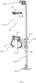
- a system 1 for filling of big bags 4 with more or less free-flowing material.
- materials can be powders such as flour, milk powder, cocoa powder, cement, chalk powder or fuel ash, but also other various types of animal feedstuffs, stone, ballast, sand or gravel or substances such as fully or partially dried sludge or filter mass can be relevant.
- the system 1 encompasses a feed pipe 5 and an associated telescopically attached outer pipe 6.
- Big bag 4 has a neck at the top, herein called beck 3, which is designed with an opening diameter such that it is just possible to feed the outer pipe 6 down into big bag 4 through the neck of the bag.
- the dosage unit 8 is shown with a funnel formed pipe 8.1, which at the lower end is connected on its underside to a radial flange 8.2 and the feed pipe is attached (yet removeable) to the flange 8.2.
- the flange 8.2 is therefore an attachment for feed pipe 5.
- On the underside 11 of the dosage unit 8 is attached a movable clamp 15, which is moved by an actuator 16, these are shown a number of times along the flange 8.2.
- the actuator 16 is set to move the clamp 15, so that it either pushes the feed pipe's radial continual interface surface 5.3 into the flange 8.2, or releases the feed pipe 5.
- 3 clamps will be fitted with associated actuators; however more or fewer can be fitted, and there may be a common actuator or an actuator associated with each clamp, as shown here.
- the elevator carriage 13.1 is permanently attached to the outer pipe 6 and as shown in Fig. 2 the outer pipe can be moved up and down on the outside of the inner pipe 5 to a position shown in Fig. 5 .
- the upper rim 6.2 of the outer pipe 6 goes to the underside of the outward facing coned part of the feed pipe 5.
- the clamps 15 can release the feed pipe so that it is no longer attached to bracket 10.
- the elevator 13 can be driven all the way down to floor level, and so the feed pipe 5 can be manually removed and another feed pipe attached, normally of a different length.
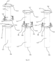
- intermediate sections can be attached removed as illustrated in Fig. 8
- Fig. 12 shows that the outward facing upper flange 5.3 on the bottom feed pipe 5.5 and the intermediate sections 5.2 has cutouts 5.7.
- On the pin 5.8 and locking arm 5.9 is attached on the upper side of the flange 5.6.
- the locking arm 5.9 allows the pin 5.8 to move downwards so that this can be fed into a cutout 5.7 and then attached and locked in one position where the pin 5.8 pulls the upper flange 5.3 into the underside of the lower flange 5.6.
- the locking arm 5.9 is shown with a handle for adjustment between the release/ locking of the pin 5.8.
- signal pin 19 is fitted which can also be seen in Fig. 11 and Fig. 12 .
- the function is shown, as the pin connection to a signal sender 20 fitted to the upper rim of the upper pipe 6. Only if the signal sender 20 is activated by the signal pin 19 is the actuator 16 permitted to release the clamps 15 to release the collective feed pipe from the bracket 10 on the underside of the dosage unit 8.
- the activation of signal sender 20 can also be used to stop further movement upwards of the elevator 13, so that this does not move further up than the interface between the outer pipe 6 upper rim 6.2 and the conical part on the bottom feed pipe.
- the system is supported by a regular machine frame 17.
- the elevator 13 is attached to the machine frame 17, and even on older systems the elevator 13 can be attached up to bracket 10 without major alterations to machine frame 17.
- the advantage here is that with the invention it is possible to rebuild older systems without replacing the machine frame and the dosage unit.
- With the invention's easy method for changing the feed pipe length it is thereby possible to use big bags of varying heights, without compromising space requirements for e.g. robot assisted handling of big bags.
- a robot unit 14 can easily be fitted as shown in Fig.
- retaining arms 18, Shown in several of the figures are the retaining arms 18, that are used to retain the big bag's neck 3 on the outer pipe during filling. It is generally known how to synchronise robot movements, to pick up empty big bags from the magazine and to place them on the outer pipe to be held by the retaining arms 18 and other parts of the filling system, so that a fully automatic system is achieved, leading to significant savings compared to slower filling systems, where big bags are presently placed manually.
Landscapes
- Engineering & Computer Science (AREA)
- Mechanical Engineering (AREA)
- Basic Packing Technique (AREA)
- Supplying Of Containers To The Packaging Station (AREA)
Applications Claiming Priority (2)
| Application Number | Priority Date | Filing Date | Title |
|---|---|---|---|
| DKPA201670087A DK179045B1 (da) | 2016-02-17 | 2016-02-17 | Fremgangsmåde til justering af anlæg for fyldning af storsække, samt anlæg til fyldning af storsække |
| PCT/DK2017/050031 WO2017140318A1 (en) | 2016-02-17 | 2017-02-08 | Method for adjustment of system for filling of big bags, and system for filling of big bags |
Publications (4)
| Publication Number | Publication Date |
|---|---|
| EP3416889A1 EP3416889A1 (en) | 2018-12-26 |
| EP3416889A4 EP3416889A4 (en) | 2019-08-14 |
| EP3416889C0 EP3416889C0 (en) | 2025-07-02 |
| EP3416889B1 true EP3416889B1 (en) | 2025-07-02 |
Family
ID=59624753
Family Applications (1)
| Application Number | Title | Priority Date | Filing Date |
|---|---|---|---|
| EP17752715.7A Active EP3416889B1 (en) | 2016-02-17 | 2017-02-08 | Method for adjustment of system for filling of big bags, and system for filling of big bags |
Country Status (9)
| Country | Link |
|---|---|
| US (2) | US11267592B2 (da) |
| EP (1) | EP3416889B1 (da) |
| AU (1) | AU2017220473C1 (da) |
| CA (1) | CA3012534C (da) |
| DK (1) | DK179045B1 (da) |
| ES (1) | ES3034584T3 (da) |
| NZ (1) | NZ745730A (da) |
| PL (1) | PL3416889T3 (da) |
| WO (1) | WO2017140318A1 (da) |
Families Citing this family (3)
| Publication number | Priority date | Publication date | Assignee | Title |
|---|---|---|---|---|
| CN111846396B (zh) * | 2019-04-30 | 2024-09-03 | 梅特勒-托利多(常州)测量技术有限公司 | 包装秤进料装置 |
| DE102019116523B4 (de) * | 2019-06-18 | 2025-03-13 | Gerhard Schubert Gmbh | Verfahren zum Wechseln eines Aggregates an einer Verpackungsstraße sowie hierfür ausgelegte Verpackungsstraße |
| CN114229053B (zh) * | 2021-11-18 | 2023-05-26 | 安徽农业大学 | 一种生物质颗粒自动化打包系统 |
Citations (1)
| Publication number | Priority date | Publication date | Assignee | Title |
|---|---|---|---|---|
| US6968670B2 (en) * | 2002-04-19 | 2005-11-29 | Webster Griffin Limited | Method of filling a bag and an apparatus for filling a bag |
Family Cites Families (19)
| Publication number | Priority date | Publication date | Assignee | Title |
|---|---|---|---|---|
| US1660442A (en) * | 1928-02-28 | Folding and siphoning funnel | ||
| BE831377A (fr) * | 1975-07-15 | 1975-11-03 | Procede et appareil pour charger des produits en vrac dans des sacs de grandes dimensions | |
| US4081004A (en) * | 1976-05-07 | 1978-03-28 | Olinkfraft, Inc. | Weighing hopper and method |
| DE2716640A1 (de) * | 1977-04-15 | 1978-10-19 | Stanelle Karl Heinz | Beladevorrichtung fuer rieselfaehiges schuettgut |
| DE2818552C2 (de) | 1978-04-27 | 1987-03-12 | Windmöller & Hölscher, 4540 Lengerich | Verfahren zum Verschließen von Großsäcken |
| DE3220780A1 (de) | 1982-06-02 | 1983-12-08 | "FIX" Peter Steimel KG, Waagen- und Maschinenbau, 5202 Hennef | Vorrichtung zum befuellen von saecken mit fliess- bzw. rieselfoermigem, insbesondere staubfoermigem fuellgut |
| DE3424613A1 (de) * | 1984-07-04 | 1986-01-16 | Günther 8068 Pfaffenhofen Hecht | Vorrichtung zum befuellen flexibler schuettgutbehaelter |
| CH678613A5 (en) | 1990-06-06 | 1991-10-15 | Sig Schweiz Industrieges | Dispenser for pourable goods into containers - consists of housing with dispensing and closure pieces, splay arms and height control |
| US5771665A (en) * | 1995-12-12 | 1998-06-30 | Nelson; W. Titus | Sand bagging system |
| ES2166694B2 (es) * | 2000-03-02 | 2003-05-01 | Payper Sa | Procedimiento de llenado en maquinas autonomas de ensacado de productos pulverulentos y boca de descarga para dichas maquinas |
| US7021026B2 (en) * | 2002-01-11 | 2006-04-04 | Delaware Capital Formation, Inc. | Netting chutes for manual and/or automated clipping packaging apparatus |
| DE20308483U1 (de) * | 2003-05-28 | 2003-09-04 | Hansen, Benno, 25938 Oevenum | Sandsackfüllmaschine |
| ES2427424T5 (es) | 2004-04-02 | 2021-11-26 | Flexicon Corp | Llenador de bolsas de granel con cabezal móvil y método correspondiente |
| WO2006020725A2 (en) * | 2004-08-11 | 2006-02-23 | Flexicon Corporation | Flexible transfer tube assembly for a bag filling system |
| DE112007002727A5 (de) * | 2006-11-27 | 2009-09-03 | Gel-Verfahrenstechnik Gmbh & Co. Kg | Verfahren und Vorrichtungen für das Befüllen von Behältern |
| HU227446B1 (en) | 2006-12-14 | 2011-06-28 | Imre Palfi | Process and equipment for filling granular bulk goods in sack |
| EP2429905A4 (en) * | 2009-05-14 | 2015-09-02 | Tipper Tie Inc | AUTOMATED PACKING APPARATUS AND ASSOCIATED DEVICE, METHOD, SYSTEMS AND COMPUTER PROGRAM PRODUCTS FOR PACKING WHOLE MUSCLES |
| NL2010537C2 (en) * | 2013-03-28 | 2014-09-30 | Tideway B V | Device and method for filling a flexible bag with material, and device and method for depositing the filled bag on the bottom of a water mass. |
| CN105059574A (zh) | 2015-08-11 | 2015-11-18 | 安徽远鸿机械自动化有限公司 | 一种粉料装袋的控制方法 |
-
2016
- 2016-02-17 DK DKPA201670087A patent/DK179045B1/da active
-
2017
- 2017-02-08 US US16/074,876 patent/US11267592B2/en active Active
- 2017-02-08 NZ NZ745730A patent/NZ745730A/en unknown
- 2017-02-08 AU AU2017220473A patent/AU2017220473C1/en active Active
- 2017-02-08 ES ES17752715T patent/ES3034584T3/es active Active
- 2017-02-08 WO PCT/DK2017/050031 patent/WO2017140318A1/en not_active Ceased
- 2017-02-08 EP EP17752715.7A patent/EP3416889B1/en active Active
- 2017-02-08 PL PL17752715.7T patent/PL3416889T3/pl unknown
- 2017-02-08 CA CA3012534A patent/CA3012534C/en active Active
-
2021
- 2021-11-10 US US17/523,752 patent/US20220063846A1/en not_active Abandoned
Patent Citations (1)
| Publication number | Priority date | Publication date | Assignee | Title |
|---|---|---|---|---|
| US6968670B2 (en) * | 2002-04-19 | 2005-11-29 | Webster Griffin Limited | Method of filling a bag and an apparatus for filling a bag |
Also Published As
| Publication number | Publication date |
|---|---|
| CA3012534C (en) | 2020-07-21 |
| EP3416889A1 (en) | 2018-12-26 |
| AU2017220473C1 (en) | 2019-11-07 |
| AU2017220473A1 (en) | 2018-09-13 |
| DK179045B1 (da) | 2017-09-18 |
| ES3034584T3 (en) | 2025-08-20 |
| US20190061980A1 (en) | 2019-02-28 |
| CA3012534A1 (en) | 2017-08-24 |
| NZ745730A (en) | 2020-01-31 |
| EP3416889A4 (en) | 2019-08-14 |
| EP3416889C0 (en) | 2025-07-02 |
| DK201670087A1 (da) | 2017-09-11 |
| US20220063846A1 (en) | 2022-03-03 |
| AU2017220473B2 (en) | 2019-08-01 |
| PL3416889T3 (pl) | 2025-09-08 |
| US11267592B2 (en) | 2022-03-08 |
| WO2017140318A1 (en) | 2017-08-24 |
Similar Documents
| Publication | Publication Date | Title |
|---|---|---|
| US20220063846A1 (en) | Method for Adjustment of System for Filling of Big Bags, and System for Filling of Big Bags | |
| US20170291727A1 (en) | Device and method for packaging flowable materials | |
| EP0575459B1 (en) | Device for delivering flowable bulk cargo | |
| CN106081653B (zh) | 一种中药提取物流系统 | |
| CA2960546A1 (en) | Device and method for filling open bags | |
| CN204019105U (zh) | 一种用于tg边板组件的自动组装设备 | |
| CN209080863U (zh) | 一种翻转提升机输送机构 | |
| US5050367A (en) | Automatic on-demand separating and placing of lids | |
| GB1436681A (en) | Automatic continuous barrel-filling method and apparatus thereof | |
| CN111003284B (zh) | 一种全自动阀口袋包装码垛生产线 | |
| CN105252682A (zh) | 轮胎硫化机存胎器 | |
| CN115750609B (zh) | 一种角接触球轴承合套机 | |
| CN208916332U (zh) | 一种浇注料进料仓斗急停装置 | |
| CN120133546A (zh) | 一种用于增材制造的清粉设备、清粉方法及应用 | |
| US3633765A (en) | Loading and unloading apparatus | |
| JP6535068B2 (ja) | 水中採掘デバイスおよび採掘方法 | |
| CN103817930A (zh) | 旋转式后置把手安装机 | |
| KR101789117B1 (ko) | 2주식 리프트형 석재 자동 흡착 이송 및 적재장치 | |
| CN208868801U (zh) | 可顶升的支承式输送带 | |
| CN115156888B (zh) | 一种泵头盖上盖机及其上盖方法 | |
| JP6689397B2 (ja) | ドライブプーリの製造方法及びその製造システムと、ローラ組付装置、ピース取付装置及びボス挿通装置 | |
| CN211035160U (zh) | 一种自动充装上盖装置 | |
| KR101408851B1 (ko) | 타이어 공기 주입장치 | |
| CN210451710U (zh) | 磁性料体的自动装管设备 | |
| CN209832108U (zh) | 一种悬辊机的辅助装置 |
Legal Events
| Date | Code | Title | Description |
|---|---|---|---|
| STAA | Information on the status of an ep patent application or granted ep patent |
Free format text: STATUS: THE INTERNATIONAL PUBLICATION HAS BEEN MADE |
|
| PUAI | Public reference made under article 153(3) epc to a published international application that has entered the european phase |
Free format text: ORIGINAL CODE: 0009012 |
|
| STAA | Information on the status of an ep patent application or granted ep patent |
Free format text: STATUS: REQUEST FOR EXAMINATION WAS MADE |
|
| 17P | Request for examination filed |
Effective date: 20180828 |
|
| AK | Designated contracting states |
Kind code of ref document: A1 Designated state(s): AL AT BE BG CH CY CZ DE DK EE ES FI FR GB GR HR HU IE IS IT LI LT LU LV MC MK MT NL NO PL PT RO RS SE SI SK SM TR |
|
| AX | Request for extension of the european patent |
Extension state: BA ME |
|
| DAV | Request for validation of the european patent (deleted) | ||
| DAX | Request for extension of the european patent (deleted) | ||
| A4 | Supplementary search report drawn up and despatched |
Effective date: 20190712 |
|
| RIC1 | Information provided on ipc code assigned before grant |
Ipc: B65B 43/54 20060101ALI20190708BHEP Ipc: B65B 39/02 20060101ALI20190708BHEP Ipc: B65B 1/06 20060101AFI20190708BHEP Ipc: B65B 39/06 20060101ALI20190708BHEP Ipc: B65B 59/04 20060101ALI20190708BHEP |
|
| STAA | Information on the status of an ep patent application or granted ep patent |
Free format text: STATUS: EXAMINATION IS IN PROGRESS |
|
| 17Q | First examination report despatched |
Effective date: 20200312 |
|
| GRAP | Despatch of communication of intention to grant a patent |
Free format text: ORIGINAL CODE: EPIDOSNIGR1 |
|
| STAA | Information on the status of an ep patent application or granted ep patent |
Free format text: STATUS: GRANT OF PATENT IS INTENDED |
|
| INTG | Intention to grant announced |
Effective date: 20250130 |
|
| GRAS | Grant fee paid |
Free format text: ORIGINAL CODE: EPIDOSNIGR3 |
|
| GRAA | (expected) grant |
Free format text: ORIGINAL CODE: 0009210 |
|
| STAA | Information on the status of an ep patent application or granted ep patent |
Free format text: STATUS: THE PATENT HAS BEEN GRANTED |
|
| AK | Designated contracting states |
Kind code of ref document: B1 Designated state(s): AL AT BE BG CH CY CZ DE DK EE ES FI FR GB GR HR HU IE IS IT LI LT LU LV MC MK MT NL NO PL PT RO RS SE SI SK SM TR |
|
| REG | Reference to a national code |
Ref country code: GB Ref legal event code: FG4D |
|
| REG | Reference to a national code |
Ref country code: CH Ref legal event code: EP |
|
| REG | Reference to a national code |
Ref country code: DE Ref legal event code: R096 Ref document number: 602017090292 Country of ref document: DE |
|
| REG | Reference to a national code |
Ref country code: IE Ref legal event code: FG4D |
|
| U01 | Request for unitary effect filed |
Effective date: 20250708 |
|
| U07 | Unitary effect registered |
Designated state(s): AT BE BG DE DK EE FI FR IT LT LU LV MT NL PT RO SE SI Effective date: 20250714 |
|
| REG | Reference to a national code |
Ref country code: ES Ref legal event code: FG2A Ref document number: 3034584 Country of ref document: ES Kind code of ref document: T3 Effective date: 20250820 |
|
| PGFP | Annual fee paid to national office [announced via postgrant information from national office to epo] |
Ref country code: GB Payment date: 20251211 Year of fee payment: 10 |
|
| U20 | Renewal fee for the european patent with unitary effect paid |
Year of fee payment: 10 Effective date: 20251211 |
|
| PG25 | Lapsed in a contracting state [announced via postgrant information from national office to epo] |
Ref country code: HR Free format text: LAPSE BECAUSE OF FAILURE TO SUBMIT A TRANSLATION OF THE DESCRIPTION OR TO PAY THE FEE WITHIN THE PRESCRIBED TIME-LIMIT Effective date: 20250702 |
|
| PG25 | Lapsed in a contracting state [announced via postgrant information from national office to epo] |
Ref country code: GR Free format text: LAPSE BECAUSE OF FAILURE TO SUBMIT A TRANSLATION OF THE DESCRIPTION OR TO PAY THE FEE WITHIN THE PRESCRIBED TIME-LIMIT Effective date: 20251003 |
|
| PG25 | Lapsed in a contracting state [announced via postgrant information from national office to epo] |
Ref country code: CZ Free format text: LAPSE BECAUSE OF FAILURE TO SUBMIT A TRANSLATION OF THE DESCRIPTION OR TO PAY THE FEE WITHIN THE PRESCRIBED TIME-LIMIT Effective date: 20250702 |
|
| PG25 | Lapsed in a contracting state [announced via postgrant information from national office to epo] |
Ref country code: RS Free format text: LAPSE BECAUSE OF FAILURE TO SUBMIT A TRANSLATION OF THE DESCRIPTION OR TO PAY THE FEE WITHIN THE PRESCRIBED TIME-LIMIT Effective date: 20251002 |
|
| REG | Reference to a national code |
Ref country code: CH Ref legal event code: U11 Free format text: ST27 STATUS EVENT CODE: U-0-0-U10-U11 (AS PROVIDED BY THE NATIONAL OFFICE) Effective date: 20260301 |
|
| PG25 | Lapsed in a contracting state [announced via postgrant information from national office to epo] |
Ref country code: SM Free format text: LAPSE BECAUSE OF FAILURE TO SUBMIT A TRANSLATION OF THE DESCRIPTION OR TO PAY THE FEE WITHIN THE PRESCRIBED TIME-LIMIT Effective date: 20250702 |
|
| PGFP | Annual fee paid to national office [announced via postgrant information from national office to epo] |
Ref country code: NO Payment date: 20260129 Year of fee payment: 10 Ref country code: IE Payment date: 20260129 Year of fee payment: 10 |
|
| PGFP | Annual fee paid to national office [announced via postgrant information from national office to epo] |
Ref country code: IS Payment date: 20260203 Year of fee payment: 10 |
|
| PGFP | Annual fee paid to national office [announced via postgrant information from national office to epo] |
Ref country code: CH Payment date: 20260301 Year of fee payment: 10 |
|
| PGFP | Annual fee paid to national office [announced via postgrant information from national office to epo] |
Ref country code: PL Payment date: 20260114 Year of fee payment: 10 |
|
| PG25 | Lapsed in a contracting state [announced via postgrant information from national office to epo] |
Ref country code: SK Free format text: LAPSE BECAUSE OF FAILURE TO SUBMIT A TRANSLATION OF THE DESCRIPTION OR TO PAY THE FEE WITHIN THE PRESCRIBED TIME-LIMIT Effective date: 20250702 |
|
| PLBE | No opposition filed within time limit |
Free format text: ORIGINAL CODE: 0009261 |
|
| STAA | Information on the status of an ep patent application or granted ep patent |
Free format text: STATUS: NO OPPOSITION FILED WITHIN TIME LIMIT |