EP3415938B1 - Verfahren und vorrichtung zum detektieren eines niederspannungsdefekts einer sekundärbatterie - Google Patents
Verfahren und vorrichtung zum detektieren eines niederspannungsdefekts einer sekundärbatterie Download PDFInfo
- Publication number
- EP3415938B1 EP3415938B1 EP18736019.3A EP18736019A EP3415938B1 EP 3415938 B1 EP3415938 B1 EP 3415938B1 EP 18736019 A EP18736019 A EP 18736019A EP 3415938 B1 EP3415938 B1 EP 3415938B1
- Authority
- EP
- European Patent Office
- Prior art keywords
- secondary battery
- rate
- low voltage
- detecting
- primary
- Prior art date
- Legal status (The legal status is an assumption and is not a legal conclusion. Google has not performed a legal analysis and makes no representation as to the accuracy of the status listed.)
- Active
Links
Images


Classifications
-
- G—PHYSICS
- G01—MEASURING; TESTING
- G01R—MEASURING ELECTRIC VARIABLES; MEASURING MAGNETIC VARIABLES
- G01R31/00—Arrangements for testing electric properties; Arrangements for locating electric faults; Arrangements for electrical testing characterised by what is being tested not provided for elsewhere
- G01R31/36—Arrangements for testing, measuring or monitoring the electrical condition of accumulators or electric batteries, e.g. capacity or state of charge [SoC]
- G01R31/385—Arrangements for measuring battery or accumulator variables
- G01R31/3865—Arrangements for measuring battery or accumulator variables related to manufacture, e.g. testing after manufacture
-
- G—PHYSICS
- G01—MEASURING; TESTING
- G01R—MEASURING ELECTRIC VARIABLES; MEASURING MAGNETIC VARIABLES
- G01R31/00—Arrangements for testing electric properties; Arrangements for locating electric faults; Arrangements for electrical testing characterised by what is being tested not provided for elsewhere
- G01R31/36—Arrangements for testing, measuring or monitoring the electrical condition of accumulators or electric batteries, e.g. capacity or state of charge [SoC]
- G01R31/385—Arrangements for measuring battery or accumulator variables
- G01R31/387—Determining ampere-hour charge capacity or SoC
- G01R31/388—Determining ampere-hour charge capacity or SoC involving voltage measurements
-
- H—ELECTRICITY
- H01—ELECTRIC ELEMENTS
- H01M—PROCESSES OR MEANS, e.g. BATTERIES, FOR THE DIRECT CONVERSION OF CHEMICAL ENERGY INTO ELECTRICAL ENERGY
- H01M10/00—Secondary cells; Manufacture thereof
- H01M10/05—Accumulators with non-aqueous electrolyte
- H01M10/052—Li-accumulators
- H01M10/0525—Rocking-chair batteries, i.e. batteries with lithium insertion or intercalation in both electrodes; Lithium-ion batteries
-
- H—ELECTRICITY
- H01—ELECTRIC ELEMENTS
- H01M—PROCESSES OR MEANS, e.g. BATTERIES, FOR THE DIRECT CONVERSION OF CHEMICAL ENERGY INTO ELECTRICAL ENERGY
- H01M10/00—Secondary cells; Manufacture thereof
- H01M10/42—Methods or arrangements for servicing or maintenance of secondary cells or secondary half-cells
- H01M10/4285—Testing apparatus
-
- H—ELECTRICITY
- H01—ELECTRIC ELEMENTS
- H01M—PROCESSES OR MEANS, e.g. BATTERIES, FOR THE DIRECT CONVERSION OF CHEMICAL ENERGY INTO ELECTRICAL ENERGY
- H01M10/00—Secondary cells; Manufacture thereof
- H01M10/42—Methods or arrangements for servicing or maintenance of secondary cells or secondary half-cells
- H01M10/44—Methods for charging or discharging
- H01M10/446—Initial charging measures
-
- H—ELECTRICITY
- H01—ELECTRIC ELEMENTS
- H01M—PROCESSES OR MEANS, e.g. BATTERIES, FOR THE DIRECT CONVERSION OF CHEMICAL ENERGY INTO ELECTRICAL ENERGY
- H01M10/00—Secondary cells; Manufacture thereof
- H01M10/42—Methods or arrangements for servicing or maintenance of secondary cells or secondary half-cells
- H01M10/48—Accumulators combined with arrangements for measuring, testing or indicating the condition of cells, e.g. the level or density of the electrolyte
-
- H—ELECTRICITY
- H01—ELECTRIC ELEMENTS
- H01M—PROCESSES OR MEANS, e.g. BATTERIES, FOR THE DIRECT CONVERSION OF CHEMICAL ENERGY INTO ELECTRICAL ENERGY
- H01M10/00—Secondary cells; Manufacture thereof
- H01M10/04—Construction or manufacture in general
- H01M10/0404—Machines for assembling batteries
-
- Y—GENERAL TAGGING OF NEW TECHNOLOGICAL DEVELOPMENTS; GENERAL TAGGING OF CROSS-SECTIONAL TECHNOLOGIES SPANNING OVER SEVERAL SECTIONS OF THE IPC; TECHNICAL SUBJECTS COVERED BY FORMER USPC CROSS-REFERENCE ART COLLECTIONS [XRACs] AND DIGESTS
- Y02—TECHNOLOGIES OR APPLICATIONS FOR MITIGATION OR ADAPTATION AGAINST CLIMATE CHANGE
- Y02E—REDUCTION OF GREENHOUSE GAS [GHG] EMISSIONS, RELATED TO ENERGY GENERATION, TRANSMISSION OR DISTRIBUTION
- Y02E60/00—Enabling technologies; Technologies with a potential or indirect contribution to GHG emissions mitigation
- Y02E60/10—Energy storage using batteries
-
- Y—GENERAL TAGGING OF NEW TECHNOLOGICAL DEVELOPMENTS; GENERAL TAGGING OF CROSS-SECTIONAL TECHNOLOGIES SPANNING OVER SEVERAL SECTIONS OF THE IPC; TECHNICAL SUBJECTS COVERED BY FORMER USPC CROSS-REFERENCE ART COLLECTIONS [XRACs] AND DIGESTS
- Y02—TECHNOLOGIES OR APPLICATIONS FOR MITIGATION OR ADAPTATION AGAINST CLIMATE CHANGE
- Y02P—CLIMATE CHANGE MITIGATION TECHNOLOGIES IN THE PRODUCTION OR PROCESSING OF GOODS
- Y02P70/00—Climate change mitigation technologies in the production process for final industrial or consumer products
- Y02P70/50—Manufacturing or production processes characterised by the final manufactured product
Definitions
- the present disclosure relates to a technique for inspecting a fault of a secondary battery, and more particularly, to a technique for effectively detecting a low voltage defect that may occur at a secondary battery.
- a secondary battery refers to a battery capable of being charged and discharged, unlike a primary battery that is not capable of being charged, and the secondary battery is widely used in electric vehicles and electronic devices such as mobile phones, notebook computers and camcorders.
- a lithium secondary battery has a larger capacity than a nickel-cadmium battery or a nickel-hydrogen battery and has a high energy density per unit weight, so its utilization is rapidly increasing.
- the lithium secondary battery mainly uses a lithium oxide and a carbonaceous material as a positive electrode active material and a negative electrode active material, respectively.
- the lithium secondary battery includes an electrode assembly having a positive electrode plate and a negative electrode plate respectively coated with the positive electrode active material and the negative electrode active material with a separator being interposed therebetween, and an exterior in which the electrode assembly is accommodated and sealed together with an electrolytic solution.
- the lithium secondary battery may be classified as a can-type secondary battery in which the electrode assembly is included in a metal can, and a pouch-type secondary battery in which the electrode assembly is included in a pouch made of aluminum laminate sheets, depending on the shape of the battery case.
- the secondary battery is generally manufactured by injecting a liquid electrolyte, namely an electrolytic solution, in a state where the electrode assembly is accommodated in the battery case, and then sealing the battery case.
- a liquid electrolyte namely an electrolytic solution
- US 2014/310951 A1 discloses a method for combining anode pre-lithiation, limited-voltage formation cycles, and accelerating aging via heated storage to maximize specific capacity, volumetric capacity density and capacity retention of a lithium-ion electrochemical cell.
- the low voltage defect of such a secondary battery is often caused by a metallic foreign substance located therein.
- a metallic foreign matter such as iron or copper on a positive electrode plate of the secondary battery
- the metallic foreign matter may grow to dendrite on a negative electrode.
- the dendrite may cause an internal short circuit of the secondary battery, which may cause a failure or damage of the secondary battery, or in severe cases, an ignition.
- the present disclosure is designed to solve the problems of the related art, and therefore the present disclosure is directed to providing a method and apparatus for detecting a low voltage defect of a secondary battery with improved performance.
- a method for detecting a low voltage defect of a secondary battery comprising: an assembling step of assembling a secondary battery by accommodating an electrode assembly, in which a positive electrode plate and a negative electrode plate are stacked with a separator being interposed therebetween, and an electrolytic solution in a battery case; a primary aging step of aging the assembled secondary battery at a temperature of 20°C to 40°C; a primary formation step of charging the aged secondary battery at a C-rate of 0.1C to 0.5C; a high-rate charging step of charging the secondary battery at a C-rate of 2C or above, after the primary formation step; and a detecting step of detecting a defect of the secondary battery, after the high-rate charging step.
- the high-rate charging step may be performed during 10 seconds to 20 seconds.
- the high-rate charging step may be performed at a temperature of 20°C to 40°C.
- the secondary battery may be charged at a C-rate of 3C or above.
- the method for detecting a low voltage defect of a secondary battery according to the present disclosure may further comprise, after the primary formation step and before the high-rate charging step, a secondary aging step of aging the secondary battery at a temperature condition of 60°C to 70°C during 12 hours to 72 hours; and a secondary formation step of charging the secondarily aged secondary battery at a C-rate of 0.1C to 2C.
- the high-rate charging step may be performed within 20 minutes to 120 minutes after the secondary formation step.
- a difference in OCV between two different points may be compared with a reference value to determine whether a defect occurs at the secondary battery.
- an apparatus for detecting a low voltage defect of a secondary battery comprising: an assembling unit configured to assemble a secondary battery by accommodating an electrode assembly, in which a positive electrode plate and a negative electrode plate are stacked with a separator being interposed therebetween, and an electrolytic solution in a battery case; a primary aging unit configured to age the secondary battery, assembled by the assembling unit, at a temperature of 20°C to 40°C; a primary formation unit configured to charge the secondary battery, aged by the primary aging unit, at a C-rate of 0.1C to 0.5C; a high-rate charging unit configured to charge the secondary battery at a C-rate of 2C or above, after the secondary battery is charged by the primary formation unit ; and a detecting unit configured to detect a defect of the secondary battery, after the secondary battery is charged by the high-rate charging unit.
- a metallic foreign matter when included in a positive electrode, it is possible to accelerate the dendritic growth of the metallic foreign matter to increase a voltage drop rate compared to a normal cell, thereby improving the low voltage detection capability.
- FIG. 1 is a schematic flowchart for illustrating a method for detecting a low voltage defect of a secondary battery according to an embodiment of the present disclosure.
- the method for detecting a low voltage defect of a secondary battery may include an assembling step (S100), a primary aging step (S210), a primary formation step (S220), a high-rate charging step (S300) and a detecting step (S400).
- a secondary battery is assembled using an electrode assembly, an electrolytic solution and a battery case.
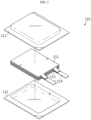
- FIG. 2 is an exploded perspective view schematically showing a secondary battery assembled in the assembling step according to an embodiment of the present disclosure
- FIG. 3 is an assembled perspective view of FIG. 2 .
- the secondary battery assembled in Step S100 may be configured so that the electrode assembly and the electrolytic solution are accommodated in the battery case.
- the electrode assembly 111 may be configured so that at least one positive electrode plate and at least one negative electrode plate are stacked with a separator being interposed therebetween.
- the electrode plates of the electrode assembly are formed by coating a current collector with active material slurry, and the slurry may be generally formed by stirring granular active material, an auxiliary conductor, a binder and a plasticizer in a state where a solvent is added thereto.
- each electrode plate may have an uncoated portion not coated with the slurry, and an electrode tab 113 corresponding to each electrode plate may be attached to the uncoated portion.
- one end of the electrode lead 114 may be attached and coupled to the electrode tab 113, and the other end of the electrode lead 114 may be exposed out of the battery case to serve as an electrode terminal that can be connected to an external device such as another secondary battery, a bus bar, a load and a charging device.
- the electrolytic solution means a liquid electrolyte, which allows ions to move between the positive electrode plate and the negative electrode plate.
- the secondary battery may be charged and discharged by means of ion exchange between the positive electrode plate and the negative electrode plate.
- non-aqueous electrolytic solutions are commonly used.
- the electrolytic solution that is useable in the secondary battery is a salt of a A+B-structure , where A+ includes an ion selected from the group consisting of alkali metal cations such as Li+, Na+, K+, or combinations thereof, and B- is an anion such as PF 6 -, BF 4 -, Cl-, Br-, I-, ClO 4 -, AsF 6 -, CH 3 CO 2 -, CF 3 SO 3 -, N (CF 3 SO 2 ) 2 -, C (CF 3 SO 2 ) 3 -, or a combination thereof.
- A+ includes an ion selected from the group consisting of alkali metal cations such as Li+, Na+, K+, or combinations thereof
- B- is an anion such as PF 6 -, BF 4 -, Cl-, Br-, I-, ClO 4 -, AsF 6 -, CH 3 CO 2 -, CF 3 SO 3 -, N (CF 3 SO 2 ) 2
- the salt may be dissolved or dissociated an organic solvent selected from the group consisting of propylene carbonate (PC), ethylene carbonate (EC), diethyl carbonate (DEC), dimethyl carbonate (DMC), dipropyl carbonate (DPC), dimethylsulfoxide, acetonitrile, dimethoxyethane, diethoxyethane, tetrahydrofuran, N-methyl-2-pyrrolidone (NMP), ethylmethyl carbonate (EMC), gamma-butyrolactone ( ⁇ -butyrolactone), and mixtures thereof, without being limited thereto.
- PC propylene carbonate
- EC ethylene carbonate
- DEC diethyl carbonate
- DMC dimethyl carbonate
- DPC dipropyl carbonate
- dimethylsulfoxide acetonitrile, dimethoxyethane, diethoxyethane, tetrahydrofuran
- NMP N-methyl-2-pyrrolidone
- the battery case 112 has an inner space in which the electrode assembly and the electrolytic solution may be accommodated.
- the battery case may be a pouch-type case in which a metal layer such as aluminum is interposed between polymer layers, and a can-type case having a cylindrical shape or an angled pillar shape made of a metal.
- the secondary battery to be inspected may be a pouch-type battery as shown in FIGS. 2 and 3 .
- the present disclosure does not necessarily relate to only the pouch-type secondary battery.
- the pouch-type case has a concave inner space, and the electrode assembly and the electrolytic solution may be accommodated in the inner space.
- the pouch-type case is composed of an upper pouch and a lower pouch, and outer peripheries thereof are fused to each other to form a sealing portion so that the inner space is sealed.
- FIGS. 2 and 3 is just an example of the secondary battery, and the secondary battery manufactured in Step S100 of the present disclosure may also be configured in various other forms.
- the secondary battery assembled in Step S100 is aged for a predetermined time.
- the manufactured secondary battery may be stored at a predetermined temperature.
- the secondary battery in the primary aging step (S210), may be stored under a temperature condition of 20°C to 40°C.
- the secondary battery in the primary aging step (S210), may be stored in a chamber where the temperature condition keeps constant. Further, in the primary aging step (S210), the secondary battery may be stored under a temperature condition of 20°C to 30°C.
- the primary aging step (S210) may be performed for a predetermined time.
- the primary aging step may be performed for 24 hours to 72 hours.
- the primary aging step may be performed for 30 hours at a temperature condition of 20°C.
- the primary aging step (S210) may be performed immediately after the secondary battery is assembled. That is, the primary aging step may be performed immediately in a state where the electrode assembly and the electrolytic solution are accommodated in the battery case and the battery case is sealed, without any other process being performed.
- the primary aging step (S210) may allow the electrolytic solution injected into the secondary battery in the assembling step (S100) to be well mixed, and may also allow the electrolytic solution to be spread well inside the battery.
- the separator is well impregnated with the electrolytic solution as a whole in order to facilitate easy ion exchange between the positive electrode plate and the negative electrode plate.
- the separator may be easily impregnated with the electrolytic solution impregnation uniformly as a whole.
- Step S220 the secondary battery primarily aged in Step S210 is charged to a predetermined SOC.
- the secondary battery in the primary formation step (S220), the secondary battery may be charged to an SOC of 30% to 40%.
- Step S220 if the SOC is too low, a solid electrolyte interphase (SEI) layer is not sufficiently generated, and thus a side reaction for additional formation for layer stabilization may occur even after the primary charging, which may cause degradation of the cell capacity.
- Step S220 if the secondary battery is charged to an excessively high SOC, the SEI layer formation reaction may be performed more than necessary to increase the irreversible capacity, thereby decreasing the cell capacity.
- the primary formation step is performed in the above SOC range.
- the secondary battery may be charged for 90 minutes to 180 minutes.
- the secondary battery may be charged at a C-rate of 0.1C to 0.5C.
- the secondary battery may be charged at a C-rate of 0.1C to 0.2C.
- the secondary battery may be charged at a C-rate of 0.1C.
- a dense and stable SEI layer may be formed.
- a polarization may be formed so that a strong charge is partially supplied, and gas is excessively generated due to excessive reaction, which may make it difficult to form a uniform SEI layer.
- the cycle performance of the secondary battery may be degraded.
- a side reaction for forming the layer may continuously occur, which may adversely affect the cell performance.
- the productivity may deteriorate.
- the primary formation step (S220) may be performed under a temperature condition of 20°C to 40°C. Moreover, the primary formation step (S220) may be performed under a temperature condition of 20°C to 30°C.
- the SEI layer may be stably formed to improve battery performance.
- the SEI layer may not be formed stably due to excessive gas generation, and an undesired side reaction such as decomposition of the electrolytic solution and the additive may occur.
- the performance of the secondary battery may deteriorate.
- the secondary battery may be charged to SOC 30% at a C-rate of 0.2C at a temperature of 25°C.
- the secondary battery may be charged with a charging voltage of 3.4V to 3.7V.
- the charging voltage may vary depending on the type and characteristic of the secondary battery.
- the primary formation step may stabilize the structure of the secondary battery and activate the secondary battery to come into an actually usable state.
- the secondary battery experiencing Step S220 is charged at a high C-rate.
- the secondary battery may be charged at a C-rate of 2C or above.
- the secondary battery may be charged at a C-rate of 3C or above.
- the high-rate charging may accelerate the growth of dendrite of a metallic foreign matter. That is, in case of a secondary battery that is highly likely to cause a low voltage defect since a metallic foreign matter is included in the secondary battery, if the secondary battery is charged at the high C-rate as above, the metallic foreign matter may grow to a dendrite faster on the negative electrode plate.
- the voltage drop rate of the secondary battery may increase resultantly, thereby improving the low voltage defect detection capability.
- the high-rate charging step (S300) may be performed for a time of 10 seconds to 20 seconds. If the high-rate charging step (S300) is performed for a shorter time, dendrite growth may not be sufficiently performed from the metallic foreign matter. Meanwhile, if the high-rate charging step is performed for a longer time, the battery voltage may reach the upper limit due to overvoltage, and the high-rate charging time may be different for various batteries due to the contact state of the charging/discharging gripper and the lead or the difference in internal resistance of the batteries.
- the high-rate charging step (S300) may be performed at a temperature condition of 20°C to 40°C.
- the high-rate charging step (S300) may be performed so that the secondary battery is charged at a high rate in a state of being exposed to room temperature.
- the metallic foreign matter may be easily extracted from the negative electrode plate, without deforming or damaging the electrode plate, the separator or the electrolytic solution of the secondary battery.
- the secondary battery in the high-rate charging step (S300), the secondary battery may be charged at a C-rate of 5C or above. Moreover, in the high-rate charging step (S300), the secondary battery may be charged at a C-rate of 10 C or above, 15 C or above, or 20 C or above. In this configuration, the dendrite growth of the metallic foreign matter is more accelerated, thereby enabling faster and more accurate detection of a low voltage defect. If the high-rate charging is applied as above, it would be more advantageous in detecting a defect of the secondary battery. Moreover, during the high-rate charging, a low voltage may be more advantageously selected by means of dOCV dispersion.
- a low voltage defect may occur as a foreign matter is included in the electrode, and if the high-rate charging is applied, it is possible to more effectively figure out the presence of the foreign matter.
- the current density of the negative electrode may be increased to facilitate the extraction (reduction reaction) of metal ions.
- acicular growth may be accelerated.
- the secondary battery may be charged at a C-rate of 20C or below. If the secondary battery is charged at a higher C-rate than 20C, Li ions may be extracted from the negative electrode, which may deteriorate the battery performance. Also, Step S300 may be performed at a C-rate of 10 C or below.
- a defect of the secondary battery may be detected after the high-rate charging step (S300).
- a defect of the secondary battery may be detected by using open circuit voltages (OCVs) measured at a plurality of different time points after the high-rate charging step (S300).
- OCVs open circuit voltages
- the secondary battery charged at a high rate in Step S300 is stored at room temperature, OCV is measured at least at two time points, and a difference value between the OCVs is compared with a reference value stored in a memory unit in advance, thereby checking the secondary battery has a defect.
- the secondary battery may be determined as having a low voltage defect.
- the voltage (OCV) of the secondary battery may be measured periodically or non-periodically at several time points.
- a low voltage defect of the secondary battery may be determined by measuring a slope of the measured voltage of the secondary battery per unit time and comparing the measured voltage slope with a reference slope.
- the OCV of the secondary battery measured at a predetermined time may be used to determine whether the secondary battery has a low voltage defect.
- various OCV measurement techniques known in the art at the time of filing of this application may be employed.
- a defect of the secondary battery may be detected by directly measuring a leakage current of the secondary battery. That is, in the detecting step (S400), after the secondary battery is charged at a high rate, while the secondary battery is being stored at room temperature, a potential may be applied to the electrode lead of the secondary battery to measure a current flowing therethrough. In this case, in the detecting step (S400), a battery having a large leakage current as compared with a normal battery may be selected as having a defect.
- FIG. 4 is a schematic flowchart for illustrating a method for detecting a low voltage defect of a secondary battery according to another embodiment of the present disclosure.
- the method may include an assembling step (S100), a primary aging step (S210), a primary formation step (S220), a secondary aging step (S230), a secondary formation step (S240), a high-rate charging step (S300) and a detecting step (S400).
- S100 a primary aging step
- S220 a primary formation step
- S230 a secondary formation step
- S240 a high-rate charging step
- S400 detecting step
- Step S230 the secondary battery experiencing the primary formation in Step S220 is aged at a predetermined temperature for a predetermined time.
- the secondary battery may be stored at a temperature condition of 60°C to 70°C.
- the secondary battery may be stored for 12 hours to 72 hours at a predetermined temperature condition.
- a portion of the electrode assembly that has insufficient wetting of the electrolytic solution may be additionally wetted, the SEI layer may be stabilized, and a metallic foreign matter not yet dissolved may be oxidized.
- Step S240 the secondary battery secondarily aged in Step S230 is charged.
- the secondary battery may be charged at a C-rate of 0.1C to 2C.
- the secondary formation step (S240) may be performed until the secondary battery is fully charged, namely until the SOC of the secondary battery becomes 100%.
- the secondary battery may be charged at a temperature condition of 20°C to 40°C.
- the secondary battery may be further discharged.
- the secondary battery may be fully discharged again so that the SOC becomes 0%.
- the secondary battery may be charged and/or discharged two times or more.
- the metallic foreign matter may be additionally oxidized, reduced and grown, and the SEI layer may be stabilized.
- the high-rate charging step (S300) may be performed after the secondary formation step (S240).
- the high-rate charging step (S300) is preferably performed within 20 minutes to 120 minutes after the secondary formation step (S240). In particular, it is recommended that Step S300 is performed within 60 minutes after Step S240.
- the method for detecting a low voltage defect of a secondary battery according to the present disclosure may further include a degassing step.
- the degassing step the gas generated inside the secondary battery is removed.
- gas may be generated inside the secondary battery.
- the degassing step the gas generated inside the secondary battery and present in the secondary battery is removed from the inside of the secondary battery to the outside.
- the degassing step may be performed after the secondary aging step (S230) and before the secondary formation step (S240).
- the degassing step may employ various degassing techniques known in the art at the time of filing of this application.
- the degassing step may be performed by cutting the elongated portion and then sealing the cut portion.
- the degassing technique is well known to those skilled in the art and thus will not be described in detail.
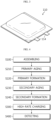
- FIG. 5 is a block diagram schematically showing a functional configuration of an apparatus for detecting a low voltage defect of a secondary battery according to an embodiment of the present disclosure.
- the apparatus for detecting a low voltage defect of a secondary battery may perform the method for detecting a low voltage defect of a secondary battery, explained above.
- the apparatus for detecting a low voltage defect of a secondary battery may include an assembling unit 110, a primary aging unit 120, a primary formation unit 130, a high-rate charging unit 140 and a detecting unit 150.
- the assembling unit may assemble a secondary battery.
- the secondary battery may include an electrode assembly and an electrolytic solution.
- the electrode assembly may be accommodated in a battery case together with the electrolytic solution.
- the battery case may be sealed in a state where the electrode assembly and the electrolytic solution are accommodated therein.
- the electrode assembly may be configured by stacking a positive electrode plate and a negative electrode plate with a separator being interposed therebetween.
- the assembling unit may be configured to perform the assembling step (S100) of the former embodiment depicted in FIGS. 1 to 4 .
- the assembling unit may include an electrode assembly stacking part for stacking the positive electrode plate, the negative electrode plate and the separator, an electrolytic solution injecting part for injecting the electrolytic solution into the battery case, a thermal fusing part for thermally fusing the battery case to be sealed, and the like.
- an electrode assembly stacking part for stacking the positive electrode plate, the negative electrode plate and the separator
- an electrolytic solution injecting part for injecting the electrolytic solution into the battery case
- a thermal fusing part for thermally fusing the battery case to be sealed, and the like.
- the primary aging unit may age the secondary battery assembled by the assembling unit.
- the primary aging unit may be configured to perform the primary aging step (S210) of the former embodiment depicted in FIGS. 1 and 4 .
- the primary aging unit may be configured to store the secondary battery for 24 hours to 72 hours at a temperature condition of 20°C to 40°C.
- the primary aging unit may include a chamber having a hollow space therein and capable of maintaining an internal temperature within a predetermined range.
- the primary formation unit may charge the secondary battery primarily aged by the primary aging unit.
- the primary formation unit may be configured to perform the primary formation step (S220) of the former embodiment depicted in FIGS. 1 and 4 .
- the primary formation unit may be configured to charge the secondary battery at a C-rate of 0.1C to 0.5C.
- the primary formation unit may also be configured to charge the secondary battery until the SOC becomes 30% to 40%.
- the primary formation unit may be configured to charge the secondary battery for 90 minutes to 180 minutes.
- the primary formation unit may also be configured to charge the secondary battery at a temperature condition of 20°C to 40°C.
- the primary formation unit may include a power generator for generating power to be supplied to the secondary battery, a connection terminal configured to contact the electrode lead of the secondary battery to transmit the power supplied from the power generator to the secondary battery, and the like.
- the high-rate charging unit may charge the secondary battery formed by the primary formation unit at a C-rate of 2C or above. Moreover, the high-rate charging unit may charge the secondary battery at a C-rate of 3C or above.
- the primary formation unit may be configured to perform the high-rate charging step (S300) in the former embodiment depicted in FIGS. 1 and 4 .
- the high-rate charging unit may be configured to charge the secondary battery for 10 seconds to 20 seconds.
- the high-rate charging unit may be configured to charge the secondary battery at a temperature condition of 20°C to 40°C.
- the high-rate charging unit may be configured to charge the secondary battery at a C-rate of 5 C or above.
- the high-rate charging unit may be configured to charge the secondary battery at a C-rate of 10 C or above, or at a C-rate of 15 C or above.
- the high-rate charging unit may include a power generator for generating power to be supplied to the secondary battery, a connection terminal formed to contact the electrode lead of the secondary battery to transmit the power supplied from the power generator to the secondary battery, and the like, similar to the primary formation unit.
- the detecting unit may detect a defect of the secondary battery charged by the high-rate charging unit.
- the detecting unit may be configured to perform the detecting step (S400) of the former embodiment depicted in FIGS. 1 and 4 .
- the detecting unit may determine whether the secondary battery has a defect by comparing a difference of two or more OCV values measured at different time points with a reference value, for the secondary battery charged at a high rate by the high-rate charging unit.
- the apparatus for detecting a low voltage defect of a secondary battery may further include a secondary aging unit 160 and a secondary formation unit 170.
- the secondary aging unit may age the secondary battery formed by the primary formation unit.
- the secondary aging unit may be configured to perform the secondary aging step (S230) of the former embodiment depicted in FIG. 4 .
- the secondary aging unit may be configured to store the secondary battery for 12 hours to 72 hours at a temperature condition of 60°C to 70°C.
- the secondary aging unit may include a chamber having a hollow space therein and capable of maintaining an internal temperature within a predetermined range.
- the secondary formation unit may form the secondary battery secondarily aged by the secondary aging unit.
- the secondary formation unit may be configured to perform the secondary formation step (S240) of the former embodiment depicted in FIG. 4 .
- the secondary formation unit may be configured to charge the secondarily aged secondary battery to the SOC of 0% to 100% at a C-rate of 0.1C to 2C.
- the secondary formation unit may be configured to charge the secondarily aged secondary battery at a temperature condition of 20°C to 40°C.
- the secondary formation unit may also be configured to discharge the secondary battery.
- the secondary formation unit may also be configured to charge and/or discharge the secondary battery two times or more.
- the secondary formation unit may include a power generator for generating a power to be supplied to the secondary battery, a connection terminal configured to contact the electrode lead of the secondary battery to transmit the power supplied from the power generator to the secondary battery, and the like.
- the secondary formation unit may further include a load or the like for receiving and consuming the power supplied from the secondary battery.
- the primary aging unit and the secondary aging unit may be implemented as a single common component. That is, one aging unit may be configured to function as both the primary aging unit and the secondary aging unit.
- at least two of the primary formation unit, the high-rate charging unit and the secondary formation unit may be implemented as one common component.
- one charging unit may be configured to function as all of the primary formation unit, the high-rate charging unit and the secondary formation unit.
- the apparatus for detecting a low voltage defect may have a simplified structure and a reduced volume. Further, in this case, the inspection process may be facilitated and the inspection time may be shortened.
- a plurality of secondary batteries were manufactured in the same manner as explained below.
- a positive electrode plate was fabricated by using aluminum current collector and LiNiMnCoO 2 as a positive electrode material
- a negative electrode plate was fabricated by using a copper current collector and graphite as a negative electrode material.
- a positive electrode plate and a negative electrode plate were stacked with a separator being interposed therebetween, and then accommodated in a pouch exterior together with an electrolytic solution.
- LiPF 6 1.0M and EC/EMC were used as the electrolytic solution.
- a plurality of secondary batteries configured as above were manufactured. At this time, for some secondary batteries, a single annular SUS304 piece with an average particle size of 100 um was inserted between the positive electrode plate and the separator as a metallic foreign matter.
- the secondary batteries prepared as above were respectively subjected to primary aging for being stored at 25°C for 72 hours, primary formation for being charged at 0.1C for 180 minutes, secondary aging for being stored at 60°C for 72 hours, degassing for removing gas from the inside of each secondary battery, and secondary formation for full charging (4.2V) and full discharge (3.0V) at 0.7C.
- the plurality of secondary batteries were divided into four groups.
- Each group included a plurality of batteries having a metallic foreign matter and a plurality of batteries having no metallic foreign matter, and the secondary batteries of each group were charged for 10 seconds at the following C-rate.
- FIG. 6 is a graph showing a measurement result of a voltage drop (dOCV) by a low voltage defect inspection method according to various examples of the present disclosure and a comparative example
- FIG. 7 is a graph showing a partial region of FIG. 6 , which is enlarged in a y-axis direction.
- a dotted line A is a reference value for the voltage drop (dOCV) and may be regarded as a reference value for determining whether a low voltage defect occurs.
- FIG. 6 in case of a battery measured to have dOCV higher than the dotted line A may be regarded as a battery at which a low voltage defect obviously occurs.
- a battery is distinguishably marked as ⁇ Bad NG'.
- a battery includes a metal foreign matter
- the voltage drop may not be distinguished using the reference value since a low voltage defect does not occur obviously. That is, in FIG. 6 , in some batteries having a metallic foreign matter, dOCV may be shown lower than the dotted line A.
- Such batteries can be regarded as batteries at which a low voltage does not occur obviously, and they are distinguishably marked as ⁇ Bad OK' in the figures.
- Example Groups 1 to 3 the proportion of secondary batteries measured as having a dOCV value higher than the dotted line A is greater, compared to the secondary batteries in Comparative Example Group 1.
- a low voltage defect can be more surely caused by the metallic foreign matter when the high-rate charging is performed after the formation as in the present disclosure. Therefore, according to the present disclosure, the possibility of a low voltage defect, caused by including a metallic foreign matter in the electrode, may be determined more quickly and more accurately.
- Example Group 3 the proportion of secondary batteries measured as having dOCV higher than the dotted line A is much higher, compared to the secondary batteries in Comparative Example Group 1 as well as the secondary batteries in Example Groups 1 and 2. That is, in each example group and comparative example group, the proportion of secondary batteries having dOCV value higher than the reference value A among all batteries having a metallic foreign matter is higher in Example Groups 1 to 3, compared to Comparative Example Group 1, and among Example Groups 1 to 3, higher in Example 2 in comparison to Example 1 and higher in Example 3 in comparison to Example 2.
- the method for detecting a low voltage defect it may also be possible to effectively distinguish a low voltage defect based on whether a metal foreign matter is included in a secondary battery even though the secondary battery has dOCV lower than the reference value.
- Example Group 1 it may be found that the dOCV overlap region of the secondary battery with a metallic foreign matter and the secondary batteries with no metallic foreign matter is decreased, compared to Comparative Example Group 1. Seeing the measurement results, it is possible to determine whether or not a metallic foreign matter is put, for the secondary batteries whose dOCV is not overlapped.
- Example Group 2 in which the C-rate of the high-rate charging step is increased in comparison to Example Group 1, it may be found that the dOCV overlap region is greatly reduced, compared with Example Group 1 as well as Comparative Example Group 1. Thus, it may be understood that the batteries with a foreign matter and the batteries without a foreign matter can be distinguished more easily, compared to Comparative Example Group 1 and Example Group 1.
- Example 3 seeing the measurement results of Example 3 in which the C-rate of the high-rate charging step is further increased, it may be found that the dOCV overlap region is further reduced. Thus, in this case, it may be understood that whether a foreign matter is put can be distinguished more reliably.
Landscapes
- Engineering & Computer Science (AREA)
- Manufacturing & Machinery (AREA)
- Chemical & Material Sciences (AREA)
- Chemical Kinetics & Catalysis (AREA)
- Electrochemistry (AREA)
- General Chemical & Material Sciences (AREA)
- Physics & Mathematics (AREA)
- General Physics & Mathematics (AREA)
- Materials Engineering (AREA)
- Secondary Cells (AREA)
Claims (8)
- Verfahren zum Detektieren eines Niederspannungsdefekts einer Sekundärbatterie, umfassend:einen Montageschritt eines Montierens einer Sekundärbatterie durch ein Aufnehmen einer Elektrodenanordnung, in welcher eine positive Elektrodenplatte und eine negative Elektrodenplatte mit einem dazwischen eingefügten Separator gestapelt sind, und einer Elektrolytlösung in einem Batteriegehäuse;einen primären Alterungsschritt eines Alterns der montierten Sekundärbatterie bei einer Temperatur von 20°C bis 40°C;einen primären Bildungsschritt eines Ladens der gealterten Sekundärbatterie mit einer C-Rate von 0,1C bis 0,5C;einen Hochgeschwindigkeitsladeschritt eines Ladens der Sekundärbatterie mit einer C-Rate von 2C oder mehr nach dem primären Bildungsschritt; undeinen Detektionsschritt eines Detektierens eines Niederspannungsdefekts der Sekundärbatterie nach dem Hochgeschwindigkeitsladeschritt.
- Verfahren zum Detektieren eines Niederspannungsdefekts einer Sekundärbatterie nach Anspruch 1,
wobei der Hochgeschwindigkeitsladeschritt für 10 Sekunden bis 20 Sekunden durchgeführt wird. - Verfahren zum Detektieren eines Niederspannungsdefekts einer Sekundärbatterie nach Anspruch 1,
wobei der Hochgeschwindigkeitsladeschritt bei einer Temperatur von 20°C bis 40°C durchgeführt wird. - Verfahren zum Detektieren eines Niederspannungsdefekts einer Sekundärbatterie nach Anspruch 1,
wobei in dem Hochgeschwindigkeitsladeschritt die Sekundärbatterie mit einer C-Rate von 3C oder mehr geladen wird. - Verfahren zum Detektieren eines Niederspannungsdefekts einer Sekundärbatterie nach Anspruch 1, nach dem primären Bildungsschritt und vor dem Hochgeschwindigkeitsladeschritt, ferner umfassend:einen sekundären Alterungsschritt eines Alterns der Sekundärbatterie bei einer Temperaturbedingung von 60°C bis 70°C für 12 Stunden bis 72 Stunden; undeinen sekundären Bildungsschritt eines Ladens der sekundär gealterten Sekundärbatterie mit einer C-Rate von 0,1C bis 2C.
- Verfahren zum Detektieren eines Niederspannungsdefekts einer Sekundärbatterie nach Anspruch 5,
wobei der Hochgeschwindigkeitsladeschritt innerhalb von 20 Minuten bis 120 Minuten nach dem sekundären Bildungsschritt durchgeführt wird. - Verfahren zum Detektieren eines Niederspannungsdefekts einer Sekundärbatterie nach Anspruch 1,
wobei in dem Detektionsschritt nach dem Hochgeschwindigkeitsladeschritt eine Differenz in einer OCV zwischen zwei verschiedenen Zeitpunkten mit einem Referenzwert verglichen wird, um zu bestimmen, ob ein Defekt an der Sekundärbatterie auftritt. - Vorrichtung zum Detektieren eines Niederspannungsdefekts einer Sekundärbatterie, umfassend:eine Montageeinheit, welche dazu eingerichtet ist, eine Sekundärbatterie durch ein Aufnehmen einer Elektrodenanordnung, in welcher eine positive Elektrodenplatte und eine negative Elektrodenplatte mit einem dazwischen eingefügten Separator gestapelt sind, und einer Elektrolytlösung in einem Batteriegehäuse zu montieren;eine primäre Alterungseinheit, welche dazu eingerichtet ist, die durch die Montageeinheit montierte Sekundärbatterie bei einer Temperatur von 20 °C bis 40 °C zu altern;eine primäre Bildungseinheit, welche dazu eingerichtet ist, die durch die primäre Alterungseinheit gealterte Sekundärbatterie mit einer C-Rate von 0,1C bis 0,5C zu laden;eine Hochgeschwindigkeitsladeeinheit, welche dazu eingerichtet ist, die Sekundärbatterie mit einer C-Rate von 2C oder mehr zu laden, nachdem die Sekundärbatterie durch die primäre Bildungseinheit geladen worden ist; undeine Detektionseinheit, welche dazu eingerichtet ist, einen Niederspannungsdefekt der Sekundärbatterie zu detektieren, nachdem die Sekundärbatterie durch die Hochgeschwindigkeitsladeeinheit geladen worden ist.
Applications Claiming Priority (2)
| Application Number | Priority Date | Filing Date | Title |
|---|---|---|---|
| KR1020170002032A KR102064459B1 (ko) | 2017-01-05 | 2017-01-05 | 이차 전지의 저전압 불량 검사 방법 및 장치 |
| PCT/KR2018/000135 WO2018128395A1 (ko) | 2017-01-05 | 2018-01-03 | 이차 전지의 저전압 불량 검사 방법 및 장치 |
Publications (3)
| Publication Number | Publication Date |
|---|---|
| EP3415938A1 EP3415938A1 (de) | 2018-12-19 |
| EP3415938A4 EP3415938A4 (de) | 2019-04-17 |
| EP3415938B1 true EP3415938B1 (de) | 2024-12-25 |
Family
ID=62789551
Family Applications (1)
| Application Number | Title | Priority Date | Filing Date |
|---|---|---|---|
| EP18736019.3A Active EP3415938B1 (de) | 2017-01-05 | 2018-01-03 | Verfahren und vorrichtung zum detektieren eines niederspannungsdefekts einer sekundärbatterie |
Country Status (8)
| Country | Link |
|---|---|
| US (1) | US10794960B2 (de) |
| EP (1) | EP3415938B1 (de) |
| KR (1) | KR102064459B1 (de) |
| CN (1) | CN108780127B (de) |
| ES (1) | ES3009601T3 (de) |
| HU (1) | HUE069939T2 (de) |
| PL (1) | PL3415938T3 (de) |
| WO (1) | WO2018128395A1 (de) |
Families Citing this family (30)
| Publication number | Priority date | Publication date | Assignee | Title |
|---|---|---|---|---|
| US11695104B2 (en) | 2019-08-23 | 2023-07-04 | Enevate Corporation | Method and system for improved performance of silicon anode containing cells through formation |
| KR102391533B1 (ko) * | 2018-10-05 | 2022-04-28 | 주식회사 엘지에너지솔루션 | 이차전지 셀의 저전압 진단 방법 및 장치 |
| US11327121B2 (en) * | 2019-04-03 | 2022-05-10 | Transportation Ip Holdings, Llc | Deviation detection system for energy storage system |
| US12377731B2 (en) * | 2019-04-03 | 2025-08-05 | Transportation Ip Holdings, Llc | Deviation detection system for power circuit |
| KR102772785B1 (ko) * | 2019-05-09 | 2025-02-27 | 주식회사 엘지에너지솔루션 | 이차전지의 제조방법 |
| KR102707046B1 (ko) * | 2019-07-02 | 2024-09-12 | 주식회사 엘지에너지솔루션 | 저전류 검사를 활용한 웨팅 정도 판별 방법 |
| KR102821892B1 (ko) | 2019-11-19 | 2025-06-18 | 주식회사 엘지에너지솔루션 | 이차전지의 활성화 방법 |
| DE102020121946A1 (de) | 2020-08-21 | 2022-02-24 | Bayerische Motoren Werke Aktiengesellschaft | Verfahren zur Untersuchung der Elektrodenbenetzung in einer Lithiumionen-Batteriezelle |
| KR102855556B1 (ko) * | 2020-08-28 | 2025-09-03 | 주식회사 엘지화학 | Al이 도핑된 NCM 양극재의 Al 도핑 여부 판단 방법 |
| KR102707237B1 (ko) | 2020-09-22 | 2024-09-20 | 주식회사 엘지에너지솔루션 | 저전압 불량 전지셀의 검출 방법 |
| KR102722397B1 (ko) * | 2020-10-16 | 2024-10-24 | 주식회사 엘지에너지솔루션 | 활성화 프로토콜 생성 방법, 이를 이용한 활성화 방법 및 활성화 장치 |
| KR20220053130A (ko) | 2020-10-22 | 2022-04-29 | 주식회사 엘지에너지솔루션 | 저전압 검출력 향상을 위한 이차 전지의 활성화 방법 |
| KR102872129B1 (ko) | 2021-01-19 | 2025-10-15 | 주식회사 엘지에너지솔루션 | 배터리 시스템 진단 장치 및 방법 |
| KR20220158507A (ko) | 2021-05-24 | 2022-12-01 | 현대자동차주식회사 | 리튬이차전지 저전압 불량 판정 방법 |
| US20240204270A1 (en) * | 2021-06-02 | 2024-06-20 | Lg Energy Solution, Ltd. | Method of Activating a Lithium Secondary Battery Including a Positive Electrode Additive |
| US11733309B2 (en) * | 2021-08-18 | 2023-08-22 | GM Global Technology Operations LLC | Method and system for self-discharge prognostics for vehicle battery cells with an internal short circuit |
| KR102839730B1 (ko) * | 2021-10-26 | 2025-07-28 | 주식회사 엘지에너지솔루션 | 이차전지의 저전압 불량 판정 시스템 및 이를 이용한 이차전지의 불량 판정 방법 |
| KR102872651B1 (ko) * | 2021-12-09 | 2025-10-16 | 주식회사 엘지에너지솔루션 | 저전압 불량 전지의 선별 방법 |
| KR102900640B1 (ko) | 2022-01-25 | 2025-12-15 | 주식회사 엘지에너지솔루션 | 리튬 이차전지의 저전압 불량 검사방법 및 리튬 이차전지의 제조방법 |
| JP7761510B2 (ja) * | 2022-03-04 | 2025-10-28 | トヨタバッテリー株式会社 | 二次電池の自己放電検査方法及び自己放電検査装置 |
| KR20230143863A (ko) | 2022-04-06 | 2023-10-13 | 에스케이온 주식회사 | 배터리 셀의 불량 판단 장치 및 방법 |
| FR3124271B1 (fr) | 2022-07-19 | 2024-08-09 | Verkor | Appareil et procédé d’inspection d’une cellule secondaire |
| FR3124270B1 (fr) | 2022-07-19 | 2024-08-09 | Verkor | Appareil et procédé d’inspection d’une cellule secondaire |
| KR102690411B1 (ko) * | 2022-09-23 | 2024-08-05 | 주식회사 엘지에너지솔루션 | 배터리 진단 장치 및 배터리 진단 방법 |
| WO2024063418A2 (ko) * | 2022-09-23 | 2024-03-28 | 주식회사 엘지에너지솔루션 | 배터리 진단 장치 및 배터리 진단 방법 |
| JP2024130715A (ja) * | 2023-03-15 | 2024-09-30 | 株式会社東芝 | 二次電池診断方法、二次電池診断装置及び二次電池診断システム |
| KR20250021022A (ko) * | 2023-08-04 | 2025-02-11 | 주식회사 엘지에너지솔루션 | 배터리 셀 검사 장치 및 이의 동작 방법 |
| KR102833835B1 (ko) * | 2023-08-31 | 2025-07-11 | 주식회사 엘지에너지솔루션 | 배터리 진단 장치 및 방법 |
| KR102825187B1 (ko) * | 2023-08-31 | 2025-06-24 | 주식회사 엘지에너지솔루션 | 배터리 진단 장치 및 방법 |
| KR102825271B1 (ko) * | 2023-08-31 | 2025-06-24 | 주식회사 엘지에너지솔루션 | 배터리 진단 장치 및 방법 |
Citations (10)
| Publication number | Priority date | Publication date | Assignee | Title |
|---|---|---|---|---|
| JPH11250930A (ja) * | 1998-03-03 | 1999-09-17 | Fuji Photo Film Co Ltd | 金属リチウム二次電池の製造システムおよびその製造方法 |
| KR101106359B1 (ko) * | 2009-09-25 | 2012-01-18 | 삼성에스디아이 주식회사 | 리튬 이온 이차 전지 제조 방법 |
| JP2015015084A (ja) * | 2013-07-03 | 2015-01-22 | トヨタ自動車株式会社 | 二次電池の製造方法 |
| JP2015153484A (ja) * | 2014-02-12 | 2015-08-24 | 株式会社豊田自動織機 | 非水系二次電池の製造方法 |
| US9214701B2 (en) * | 2010-10-05 | 2015-12-15 | Shin-Kobe Electric Machinery Co., Ltd. | Lithium-ion rechargeable battery |
| CN105609889A (zh) * | 2015-12-17 | 2016-05-25 | 中天储能科技有限公司 | 一种圆柱锂电池快速化成分容方法 |
| KR20160065965A (ko) * | 2013-11-11 | 2016-06-09 | 도요타지도샤가부시키가이샤 | 비수계 이차 전지의 제조 방법 |
| KR102200911B1 (ko) * | 2013-01-30 | 2021-01-08 | 나노스캐일 컴포넌츠, 인코포레이티드 | 리튬 이온 전기화학적 셀의 사전-리튬화반응된 애노드로의 리튬의 단계적 도입 |
| US20230084079A1 (en) * | 2020-09-22 | 2023-03-16 | Lg Energy Solution, Ltd. | Method for detecting low voltage battery cell |
| US20240044987A1 (en) * | 2021-12-09 | 2024-02-08 | Lg Energy Solution, Ltd. | Method for screening low-voltage defective battery |
Family Cites Families (12)
| Publication number | Priority date | Publication date | Assignee | Title |
|---|---|---|---|---|
| JP3376718B2 (ja) * | 1994-10-17 | 2003-02-10 | 日産自動車株式会社 | 充電システム |
| US8120328B2 (en) * | 2006-03-24 | 2012-02-21 | Nec Corporation | Charging system, charging control program, and portable terminal |
| JP2008228492A (ja) * | 2007-03-14 | 2008-09-25 | Sanyo Electric Co Ltd | リチウムイオン二次電池の充電方法 |
| JP4725594B2 (ja) * | 2008-04-04 | 2011-07-13 | トヨタ自動車株式会社 | リチウム二次電池の製造方法 |
| DE102008046510A1 (de) * | 2008-09-10 | 2010-03-11 | Li-Tec Battery Gmbh | Nach galvanischen Prinzipien arbeitende elektrische Einrichtungen, wie beispielsweise Lithium-Ionen-Zelle, mit einer Betriebszustandssteuerung |
| CN101950815B (zh) | 2010-08-23 | 2013-09-11 | 八叶(厦门)新能源科技有限公司 | 一种圆柱型锂离子二次电池化成的方法 |
| US9197096B2 (en) * | 2012-01-19 | 2015-11-24 | Apple Inc. | Charging techniques for solid-state batteries in portable electronic devices |
| US9590439B2 (en) * | 2012-10-22 | 2017-03-07 | Toyota Jidosha Kabushiki Kaisha | Control device of battery charging |
| WO2015127115A1 (en) * | 2014-02-19 | 2015-08-27 | The Regents Of The University Of Michigan | Dendrite-suppressing ion-conductors from aramid nanofibers withstanding extreme battery conditions |
| CN105514350A (zh) * | 2014-09-25 | 2016-04-20 | 东莞新能源科技有限公司 | 锂离子电池 |
| DE102014219635A1 (de) | 2014-09-29 | 2016-03-31 | Siemens Aktiengesellschaft | Fahrzeugbatterietesteinrichtung und Fahrzeugbatterietestverfahren |
| CN104362348A (zh) * | 2014-11-06 | 2015-02-18 | 东莞新能源科技有限公司 | 一种负极电极膜及应用了该电极膜的锂离子电池 |
-
2017
- 2017-01-05 KR KR1020170002032A patent/KR102064459B1/ko active Active
-
2018
- 2018-01-03 ES ES18736019T patent/ES3009601T3/es active Active
- 2018-01-03 WO PCT/KR2018/000135 patent/WO2018128395A1/ko not_active Ceased
- 2018-01-03 HU HUE18736019A patent/HUE069939T2/hu unknown
- 2018-01-03 CN CN201880001348.9A patent/CN108780127B/zh active Active
- 2018-01-03 EP EP18736019.3A patent/EP3415938B1/de active Active
- 2018-01-03 PL PL18736019.3T patent/PL3415938T3/pl unknown
- 2018-01-03 US US16/078,532 patent/US10794960B2/en active Active
Patent Citations (10)
| Publication number | Priority date | Publication date | Assignee | Title |
|---|---|---|---|---|
| JPH11250930A (ja) * | 1998-03-03 | 1999-09-17 | Fuji Photo Film Co Ltd | 金属リチウム二次電池の製造システムおよびその製造方法 |
| KR101106359B1 (ko) * | 2009-09-25 | 2012-01-18 | 삼성에스디아이 주식회사 | 리튬 이온 이차 전지 제조 방법 |
| US9214701B2 (en) * | 2010-10-05 | 2015-12-15 | Shin-Kobe Electric Machinery Co., Ltd. | Lithium-ion rechargeable battery |
| KR102200911B1 (ko) * | 2013-01-30 | 2021-01-08 | 나노스캐일 컴포넌츠, 인코포레이티드 | 리튬 이온 전기화학적 셀의 사전-리튬화반응된 애노드로의 리튬의 단계적 도입 |
| JP2015015084A (ja) * | 2013-07-03 | 2015-01-22 | トヨタ自動車株式会社 | 二次電池の製造方法 |
| KR20160065965A (ko) * | 2013-11-11 | 2016-06-09 | 도요타지도샤가부시키가이샤 | 비수계 이차 전지의 제조 방법 |
| JP2015153484A (ja) * | 2014-02-12 | 2015-08-24 | 株式会社豊田自動織機 | 非水系二次電池の製造方法 |
| CN105609889A (zh) * | 2015-12-17 | 2016-05-25 | 中天储能科技有限公司 | 一种圆柱锂电池快速化成分容方法 |
| US20230084079A1 (en) * | 2020-09-22 | 2023-03-16 | Lg Energy Solution, Ltd. | Method for detecting low voltage battery cell |
| US20240044987A1 (en) * | 2021-12-09 | 2024-02-08 | Lg Energy Solution, Ltd. | Method for screening low-voltage defective battery |
Also Published As
| Publication number | Publication date |
|---|---|
| PL3415938T3 (pl) | 2025-03-10 |
| ES3009601T3 (en) | 2025-03-27 |
| HUE069939T2 (hu) | 2025-04-28 |
| EP3415938A1 (de) | 2018-12-19 |
| KR20180080914A (ko) | 2018-07-13 |
| CN108780127B (zh) | 2021-09-07 |
| EP3415938A4 (de) | 2019-04-17 |
| CN108780127A (zh) | 2018-11-09 |
| KR102064459B1 (ko) | 2020-01-09 |
| US20190033380A1 (en) | 2019-01-31 |
| WO2018128395A1 (ko) | 2018-07-12 |
| US10794960B2 (en) | 2020-10-06 |
Similar Documents
| Publication | Publication Date | Title |
|---|---|---|
| EP3415938B1 (de) | Verfahren und vorrichtung zum detektieren eines niederspannungsdefekts einer sekundärbatterie | |
| US12272792B2 (en) | Method for manufacturing secondary battery | |
| Brand et al. | Electrical safety of commercial Li-ion cells based on NMC and NCA technology compared to LFP technology | |
| KR100793011B1 (ko) | 리튬이차전지의 제조방법 | |
| KR100793010B1 (ko) | 리튬이차전지의 제조방법 | |
| EP4083644B1 (de) | Verfahren zum detektieren einer niederspannungsbatteriezelle | |
| EP3800719B1 (de) | Sekundärbatterieaktivierungsverfahren mit erhöhter fähigkeit zur detektion von niedriger spannung | |
| US20180164384A1 (en) | Method and apparatus for assessing lifespan of secondary battery | |
| US12095070B2 (en) | Secondary battery formation method | |
| EP4060788B1 (de) | Verfahren zur aktivierung einer sekundärbatterie | |
| KR102194845B1 (ko) | 이차 전지의 저전압 불량 검사 장치 및 방법 | |
| US10539627B2 (en) | Method of restoring secondary battery and method of reusing secondary battery | |
| KR20210030089A (ko) | 활성화 공정에서의 이차전지 셀 검사 방법 및 장치 | |
| JP7011782B2 (ja) | 二次電池の検査方法 | |
| JP2014082121A (ja) | 非水電解液二次電池の製造方法 | |
| JP2023083043A (ja) | 非水電解液二次電池の検査方法 | |
| KR101839405B1 (ko) | 메모리 칩의 파손 여부를 감지하는 검출 소자를 포함하는 보호회로 및 이를 포함하는 이차전지 팩 | |
| US20240088441A1 (en) | Non-aqueous electrolyte rechargeable battery and method for manufacturing non-aqueous electrolyte rechargeable battery | |
| KR20220104906A (ko) | 활성화 공정에서의 이차전지 셀 검사 방법 | |
| KR20220017642A (ko) | 이차 전지 제조 방법 | |
| JP2023096944A (ja) | 非水電解液二次電池の検査方法 | |
| WO2025115838A1 (ja) | 二次電池の検査方法 | |
| KR20220053130A (ko) | 저전압 검출력 향상을 위한 이차 전지의 활성화 방법 |
Legal Events
| Date | Code | Title | Description |
|---|---|---|---|
| STAA | Information on the status of an ep patent application or granted ep patent |
Free format text: STATUS: THE INTERNATIONAL PUBLICATION HAS BEEN MADE |
|
| PUAI | Public reference made under article 153(3) epc to a published international application that has entered the european phase |
Free format text: ORIGINAL CODE: 0009012 |
|
| STAA | Information on the status of an ep patent application or granted ep patent |
Free format text: STATUS: REQUEST FOR EXAMINATION WAS MADE |
|
| 17P | Request for examination filed |
Effective date: 20180914 |
|
| AK | Designated contracting states |
Kind code of ref document: A1 Designated state(s): AL AT BE BG CH CY CZ DE DK EE ES FI FR GB GR HR HU IE IS IT LI LT LU LV MC MK MT NL NO PL PT RO RS SE SI SK SM TR |
|
| AX | Request for extension of the european patent |
Extension state: BA ME |
|
| A4 | Supplementary search report drawn up and despatched |
Effective date: 20190320 |
|
| RIC1 | Information provided on ipc code assigned before grant |
Ipc: G01R 31/385 20190101ALI20190314BHEP Ipc: H01M 10/04 20060101ALN20190314BHEP Ipc: G01R 31/388 20190101ALI20190314BHEP Ipc: H01M 10/0525 20100101ALI20190314BHEP Ipc: H01M 10/44 20060101ALI20190314BHEP Ipc: H01M 10/42 20060101AFI20190314BHEP Ipc: G01R 31/36 20190101ALI20190314BHEP Ipc: H01M 10/48 20060101ALI20190314BHEP |
|
| DAV | Request for validation of the european patent (deleted) | ||
| DAX | Request for extension of the european patent (deleted) | ||
| RAP1 | Party data changed (applicant data changed or rights of an application transferred) |
Owner name: LG ENERGY SOLUTION LTD. |
|
| RAP3 | Party data changed (applicant data changed or rights of an application transferred) |
Owner name: LG ENERGY SOLUTION, LTD. |
|
| GRAP | Despatch of communication of intention to grant a patent |
Free format text: ORIGINAL CODE: EPIDOSNIGR1 |
|
| STAA | Information on the status of an ep patent application or granted ep patent |
Free format text: STATUS: GRANT OF PATENT IS INTENDED |
|
| INTG | Intention to grant announced |
Effective date: 20240719 |
|
| P01 | Opt-out of the competence of the unified patent court (upc) registered |
Free format text: CASE NUMBER: APP_44500/2024 Effective date: 20240731 |
|
| GRAS | Grant fee paid |
Free format text: ORIGINAL CODE: EPIDOSNIGR3 |
|
| GRAA | (expected) grant |
Free format text: ORIGINAL CODE: 0009210 |
|
| STAA | Information on the status of an ep patent application or granted ep patent |
Free format text: STATUS: THE PATENT HAS BEEN GRANTED |
|
| AK | Designated contracting states |
Kind code of ref document: B1 Designated state(s): AL AT BE BG CH CY CZ DE DK EE ES FI FR GB GR HR HU IE IS IT LI LT LU LV MC MK MT NL NO PL PT RO RS SE SI SK SM TR |
|
| REG | Reference to a national code |
Ref country code: GB Ref legal event code: FG4D |
|
| REG | Reference to a national code |
Ref country code: CH Ref legal event code: EP |
|
| REG | Reference to a national code |
Ref country code: DE Ref legal event code: R096 Ref document number: 602018077913 Country of ref document: DE |
|
| REG | Reference to a national code |
Ref country code: IE Ref legal event code: FG4D |
|
| REG | Reference to a national code |
Ref country code: SE Ref legal event code: TRGR |
|
| REG | Reference to a national code |
Ref country code: ES Ref legal event code: FG2A Ref document number: 3009601 Country of ref document: ES Kind code of ref document: T3 Effective date: 20250327 |
|
| REG | Reference to a national code |
Ref country code: LT Ref legal event code: MG9D |
|
| PG25 | Lapsed in a contracting state [announced via postgrant information from national office to epo] |
Ref country code: HR Free format text: LAPSE BECAUSE OF FAILURE TO SUBMIT A TRANSLATION OF THE DESCRIPTION OR TO PAY THE FEE WITHIN THE PRESCRIBED TIME-LIMIT Effective date: 20241225 |
|
| PG25 | Lapsed in a contracting state [announced via postgrant information from national office to epo] |
Ref country code: FI Free format text: LAPSE BECAUSE OF FAILURE TO SUBMIT A TRANSLATION OF THE DESCRIPTION OR TO PAY THE FEE WITHIN THE PRESCRIBED TIME-LIMIT Effective date: 20241225 |
|
| PG25 | Lapsed in a contracting state [announced via postgrant information from national office to epo] |
Ref country code: BG Free format text: LAPSE BECAUSE OF FAILURE TO SUBMIT A TRANSLATION OF THE DESCRIPTION OR TO PAY THE FEE WITHIN THE PRESCRIBED TIME-LIMIT Effective date: 20241225 |
|
| PG25 | Lapsed in a contracting state [announced via postgrant information from national office to epo] |
Ref country code: NO Free format text: LAPSE BECAUSE OF FAILURE TO SUBMIT A TRANSLATION OF THE DESCRIPTION OR TO PAY THE FEE WITHIN THE PRESCRIBED TIME-LIMIT Effective date: 20250325 |
|
| PG25 | Lapsed in a contracting state [announced via postgrant information from national office to epo] |
Ref country code: LV Free format text: LAPSE BECAUSE OF FAILURE TO SUBMIT A TRANSLATION OF THE DESCRIPTION OR TO PAY THE FEE WITHIN THE PRESCRIBED TIME-LIMIT Effective date: 20241225 Ref country code: GR Free format text: LAPSE BECAUSE OF FAILURE TO SUBMIT A TRANSLATION OF THE DESCRIPTION OR TO PAY THE FEE WITHIN THE PRESCRIBED TIME-LIMIT Effective date: 20250326 |
|
| REG | Reference to a national code |
Ref country code: HU Ref legal event code: AG4A Ref document number: E069939 Country of ref document: HU |
|
| PG25 | Lapsed in a contracting state [announced via postgrant information from national office to epo] |
Ref country code: RS Free format text: LAPSE BECAUSE OF FAILURE TO SUBMIT A TRANSLATION OF THE DESCRIPTION OR TO PAY THE FEE WITHIN THE PRESCRIBED TIME-LIMIT Effective date: 20250325 |
|
| REG | Reference to a national code |
Ref country code: NL Ref legal event code: MP Effective date: 20241225 |
|
| PG25 | Lapsed in a contracting state [announced via postgrant information from national office to epo] |
Ref country code: NL Free format text: LAPSE BECAUSE OF FAILURE TO SUBMIT A TRANSLATION OF THE DESCRIPTION OR TO PAY THE FEE WITHIN THE PRESCRIBED TIME-LIMIT Effective date: 20241225 |
|
| REG | Reference to a national code |
Ref country code: AT Ref legal event code: MK05 Ref document number: 1754977 Country of ref document: AT Kind code of ref document: T Effective date: 20241225 |
|
| PG25 | Lapsed in a contracting state [announced via postgrant information from national office to epo] |
Ref country code: SM Free format text: LAPSE BECAUSE OF FAILURE TO SUBMIT A TRANSLATION OF THE DESCRIPTION OR TO PAY THE FEE WITHIN THE PRESCRIBED TIME-LIMIT Effective date: 20241225 |
|
| PG25 | Lapsed in a contracting state [announced via postgrant information from national office to epo] |
Ref country code: IS Free format text: LAPSE BECAUSE OF FAILURE TO SUBMIT A TRANSLATION OF THE DESCRIPTION OR TO PAY THE FEE WITHIN THE PRESCRIBED TIME-LIMIT Effective date: 20250425 |
|
| PG25 | Lapsed in a contracting state [announced via postgrant information from national office to epo] |
Ref country code: PT Free format text: LAPSE BECAUSE OF FAILURE TO SUBMIT A TRANSLATION OF THE DESCRIPTION OR TO PAY THE FEE WITHIN THE PRESCRIBED TIME-LIMIT Effective date: 20250428 |
|
| PG25 | Lapsed in a contracting state [announced via postgrant information from national office to epo] |
Ref country code: EE Free format text: LAPSE BECAUSE OF FAILURE TO SUBMIT A TRANSLATION OF THE DESCRIPTION OR TO PAY THE FEE WITHIN THE PRESCRIBED TIME-LIMIT Effective date: 20241225 |
|
| PG25 | Lapsed in a contracting state [announced via postgrant information from national office to epo] |
Ref country code: AT Free format text: LAPSE BECAUSE OF FAILURE TO SUBMIT A TRANSLATION OF THE DESCRIPTION OR TO PAY THE FEE WITHIN THE PRESCRIBED TIME-LIMIT Effective date: 20241225 Ref country code: RO Free format text: LAPSE BECAUSE OF FAILURE TO SUBMIT A TRANSLATION OF THE DESCRIPTION OR TO PAY THE FEE WITHIN THE PRESCRIBED TIME-LIMIT Effective date: 20241225 |
|
| PG25 | Lapsed in a contracting state [announced via postgrant information from national office to epo] |
Ref country code: SK Free format text: LAPSE BECAUSE OF FAILURE TO SUBMIT A TRANSLATION OF THE DESCRIPTION OR TO PAY THE FEE WITHIN THE PRESCRIBED TIME-LIMIT Effective date: 20241225 |
|
| PG25 | Lapsed in a contracting state [announced via postgrant information from national office to epo] |
Ref country code: CZ Free format text: LAPSE BECAUSE OF FAILURE TO SUBMIT A TRANSLATION OF THE DESCRIPTION OR TO PAY THE FEE WITHIN THE PRESCRIBED TIME-LIMIT Effective date: 20241225 |
|
| PG25 | Lapsed in a contracting state [announced via postgrant information from national office to epo] |
Ref country code: IT Free format text: LAPSE BECAUSE OF FAILURE TO SUBMIT A TRANSLATION OF THE DESCRIPTION OR TO PAY THE FEE WITHIN THE PRESCRIBED TIME-LIMIT Effective date: 20241225 |
|
| REG | Reference to a national code |
Ref country code: CH Ref legal event code: PL |
|
| PG25 | Lapsed in a contracting state [announced via postgrant information from national office to epo] |
Ref country code: MC Free format text: LAPSE BECAUSE OF FAILURE TO SUBMIT A TRANSLATION OF THE DESCRIPTION OR TO PAY THE FEE WITHIN THE PRESCRIBED TIME-LIMIT Effective date: 20241225 Ref country code: LU Free format text: LAPSE BECAUSE OF NON-PAYMENT OF DUE FEES Effective date: 20250103 |
|
| REG | Reference to a national code |
Ref country code: DE Ref legal event code: R097 Ref document number: 602018077913 Country of ref document: DE |
|
| PG25 | Lapsed in a contracting state [announced via postgrant information from national office to epo] |
Ref country code: DK Free format text: LAPSE BECAUSE OF FAILURE TO SUBMIT A TRANSLATION OF THE DESCRIPTION OR TO PAY THE FEE WITHIN THE PRESCRIBED TIME-LIMIT Effective date: 20241225 |
|
| PG25 | Lapsed in a contracting state [announced via postgrant information from national office to epo] |
Ref country code: CH Free format text: LAPSE BECAUSE OF NON-PAYMENT OF DUE FEES Effective date: 20250131 |
|
| PLBE | No opposition filed within time limit |
Free format text: ORIGINAL CODE: 0009261 |
|
| STAA | Information on the status of an ep patent application or granted ep patent |
Free format text: STATUS: NO OPPOSITION FILED WITHIN TIME LIMIT |
|
| 26N | No opposition filed |
Effective date: 20250926 |
|
| PGFP | Annual fee paid to national office [announced via postgrant information from national office to epo] |
Ref country code: GB Payment date: 20251222 Year of fee payment: 9 |
|
| PGFP | Annual fee paid to national office [announced via postgrant information from national office to epo] |
Ref country code: FR Payment date: 20251223 Year of fee payment: 9 |
|
| PGFP | Annual fee paid to national office [announced via postgrant information from national office to epo] |
Ref country code: BE Payment date: 20251229 Year of fee payment: 9 |
|
| PGFP | Annual fee paid to national office [announced via postgrant information from national office to epo] |
Ref country code: SE Payment date: 20251223 Year of fee payment: 9 |
|
| PG25 | Lapsed in a contracting state [announced via postgrant information from national office to epo] |
Ref country code: IE Free format text: LAPSE BECAUSE OF NON-PAYMENT OF DUE FEES Effective date: 20250103 |
|
| PGFP | Annual fee paid to national office [announced via postgrant information from national office to epo] |
Ref country code: PL Payment date: 20251223 Year of fee payment: 9 |
|
| PGFP | Annual fee paid to national office [announced via postgrant information from national office to epo] |
Ref country code: HU Payment date: 20260129 Year of fee payment: 9 |
|
| PGFP | Annual fee paid to national office [announced via postgrant information from national office to epo] |
Ref country code: ES Payment date: 20260212 Year of fee payment: 9 |
|
| PGFP | Annual fee paid to national office [announced via postgrant information from national office to epo] |
Ref country code: DE Payment date: 20251222 Year of fee payment: 9 |