EP3415062A1 - Elektromotorisch betriebene küchenmaschine - Google Patents
Elektromotorisch betriebene küchenmaschine Download PDFInfo
- Publication number
- EP3415062A1 EP3415062A1 EP18177320.1A EP18177320A EP3415062A1 EP 3415062 A1 EP3415062 A1 EP 3415062A1 EP 18177320 A EP18177320 A EP 18177320A EP 3415062 A1 EP3415062 A1 EP 3415062A1
- Authority
- EP
- European Patent Office
- Prior art keywords
- food processor
- preparation vessel
- distillation
- vapor
- vessel
- Prior art date
- Legal status (The legal status is an assumption and is not a legal conclusion. Google has not performed a legal analysis and makes no representation as to the accuracy of the status listed.)
- Granted
Links
Images


Classifications
-
- B—PERFORMING OPERATIONS; TRANSPORTING
- B01—PHYSICAL OR CHEMICAL PROCESSES OR APPARATUS IN GENERAL
- B01D—SEPARATION
- B01D3/00—Distillation or related exchange processes in which liquids are contacted with gaseous media, e.g. stripping
- B01D3/001—Processes specially adapted for distillation or rectification of fermented solutions
-
- A—HUMAN NECESSITIES
- A47—FURNITURE; DOMESTIC ARTICLES OR APPLIANCES; COFFEE MILLS; SPICE MILLS; SUCTION CLEANERS IN GENERAL
- A47J—KITCHEN EQUIPMENT; COFFEE MILLS; SPICE MILLS; APPARATUS FOR MAKING BEVERAGES
- A47J43/00—Implements for preparing or holding food, not provided for in other groups of this subclass
- A47J43/04—Machines for domestic use not covered elsewhere, e.g. for grinding, mixing, stirring, kneading, emulsifying, whipping or beating foodstuffs, e.g. power-driven
- A47J43/07—Parts or details, e.g. mixing tools, whipping tools
- A47J43/0716—Parts or details, e.g. mixing tools, whipping tools for machines with tools driven from the lower side
- A47J43/0722—Mixing, whipping or cutting tools
-
- A—HUMAN NECESSITIES
- A47—FURNITURE; DOMESTIC ARTICLES OR APPLIANCES; COFFEE MILLS; SPICE MILLS; SUCTION CLEANERS IN GENERAL
- A47J—KITCHEN EQUIPMENT; COFFEE MILLS; SPICE MILLS; APPARATUS FOR MAKING BEVERAGES
- A47J43/00—Implements for preparing or holding food, not provided for in other groups of this subclass
- A47J43/04—Machines for domestic use not covered elsewhere, e.g. for grinding, mixing, stirring, kneading, emulsifying, whipping or beating foodstuffs, e.g. power-driven
- A47J43/07—Parts or details, e.g. mixing tools, whipping tools
-
- A—HUMAN NECESSITIES
- A47—FURNITURE; DOMESTIC ARTICLES OR APPLIANCES; COFFEE MILLS; SPICE MILLS; SUCTION CLEANERS IN GENERAL
- A47J—KITCHEN EQUIPMENT; COFFEE MILLS; SPICE MILLS; APPARATUS FOR MAKING BEVERAGES
- A47J43/00—Implements for preparing or holding food, not provided for in other groups of this subclass
- A47J43/04—Machines for domestic use not covered elsewhere, e.g. for grinding, mixing, stirring, kneading, emulsifying, whipping or beating foodstuffs, e.g. power-driven
- A47J43/07—Parts or details, e.g. mixing tools, whipping tools
- A47J43/0716—Parts or details, e.g. mixing tools, whipping tools for machines with tools driven from the lower side
-
- A—HUMAN NECESSITIES
- A47—FURNITURE; DOMESTIC ARTICLES OR APPLIANCES; COFFEE MILLS; SPICE MILLS; SUCTION CLEANERS IN GENERAL
- A47J—KITCHEN EQUIPMENT; COFFEE MILLS; SPICE MILLS; APPARATUS FOR MAKING BEVERAGES
- A47J44/00—Multi-purpose machines for preparing food with several driving units
- A47J44/02—Multi-purpose machines for preparing food with several driving units with provisions for drive either from top or from bottom, e.g. for separately-driven bowl
-
- B—PERFORMING OPERATIONS; TRANSPORTING
- B01—PHYSICAL OR CHEMICAL PROCESSES OR APPARATUS IN GENERAL
- B01D—SEPARATION
- B01D3/00—Distillation or related exchange processes in which liquids are contacted with gaseous media, e.g. stripping
- B01D3/001—Processes specially adapted for distillation or rectification of fermented solutions
- B01D3/003—Rectification of spirit
-
- B—PERFORMING OPERATIONS; TRANSPORTING
- B01—PHYSICAL OR CHEMICAL PROCESSES OR APPARATUS IN GENERAL
- B01D—SEPARATION
- B01D5/00—Condensation of vapours; Recovering volatile solvents by condensation
- B01D5/0033—Other features
- B01D5/0042—Thermo-electric condensing; using Peltier-effect
-
- B—PERFORMING OPERATIONS; TRANSPORTING
- B01—PHYSICAL OR CHEMICAL PROCESSES OR APPARATUS IN GENERAL
- B01D—SEPARATION
- B01D5/00—Condensation of vapours; Recovering volatile solvents by condensation
- B01D5/0057—Condensation of vapours; Recovering volatile solvents by condensation in combination with other processes
- B01D5/006—Condensation of vapours; Recovering volatile solvents by condensation in combination with other processes with evaporation or distillation
-
- B—PERFORMING OPERATIONS; TRANSPORTING
- B02—CRUSHING, PULVERISING, OR DISINTEGRATING; PREPARATORY TREATMENT OF GRAIN FOR MILLING
- B02C—CRUSHING, PULVERISING, OR DISINTEGRATING IN GENERAL; MILLING GRAIN
- B02C9/00—Other milling methods or mills specially adapted for grain
- B02C9/02—Cutting or splitting grain
-
- C—CHEMISTRY; METALLURGY
- C12—BIOCHEMISTRY; BEER; SPIRITS; WINE; VINEGAR; MICROBIOLOGY; ENZYMOLOGY; MUTATION OR GENETIC ENGINEERING
- C12C—BEER; PREPARATION OF BEER BY FERMENTATION; PREPARATION OF MALT FOR MAKING BEER; PREPARATION OF HOPS FOR MAKING BEER
- C12C13/00—Brewing devices, not covered by a single group of C12C1/00 - C12C12/04
- C12C13/10—Home brew equipment
-
- C—CHEMISTRY; METALLURGY
- C12—BIOCHEMISTRY; BEER; SPIRITS; WINE; VINEGAR; MICROBIOLOGY; ENZYMOLOGY; MUTATION OR GENETIC ENGINEERING
- C12C—BEER; PREPARATION OF BEER BY FERMENTATION; PREPARATION OF MALT FOR MAKING BEER; PREPARATION OF HOPS FOR MAKING BEER
- C12C7/00—Preparation of wort
- C12C7/01—Pretreatment of malt, e.g. malt grinding
-
- C—CHEMISTRY; METALLURGY
- C12—BIOCHEMISTRY; BEER; SPIRITS; WINE; VINEGAR; MICROBIOLOGY; ENZYMOLOGY; MUTATION OR GENETIC ENGINEERING
- C12H—PASTEURISATION, STERILISATION, PRESERVATION, PURIFICATION, CLARIFICATION OR AGEING OF ALCOHOLIC BEVERAGES; METHODS FOR ALTERING THE ALCOHOL CONTENT OF FERMENTED SOLUTIONS OR ALCOHOLIC BEVERAGES
- C12H6/00—Methods for increasing the alcohol content of fermented solutions or alcoholic beverages
- C12H6/02—Methods for increasing the alcohol content of fermented solutions or alcoholic beverages by distillation
-
- B—PERFORMING OPERATIONS; TRANSPORTING
- B01—PHYSICAL OR CHEMICAL PROCESSES OR APPARATUS IN GENERAL
- B01D—SEPARATION
- B01D5/00—Condensation of vapours; Recovering volatile solvents by condensation
- B01D5/0078—Condensation of vapours; Recovering volatile solvents by condensation characterised by auxiliary systems or arrangements
- B01D5/0081—Feeding the steam or the vapours
-
- Y—GENERAL TAGGING OF NEW TECHNOLOGICAL DEVELOPMENTS; GENERAL TAGGING OF CROSS-SECTIONAL TECHNOLOGIES SPANNING OVER SEVERAL SECTIONS OF THE IPC; TECHNICAL SUBJECTS COVERED BY FORMER USPC CROSS-REFERENCE ART COLLECTIONS [XRACs] AND DIGESTS
- Y02—TECHNOLOGIES OR APPLICATIONS FOR MITIGATION OR ADAPTATION AGAINST CLIMATE CHANGE
- Y02A—TECHNOLOGIES FOR ADAPTATION TO CLIMATE CHANGE
- Y02A20/00—Water conservation; Efficient water supply; Efficient water use
Definitions
- the invention relates to an electromotive-operated food processor with a basic unit having an electric motor and a preparation vessel which can be arranged on the base unit, to which preparation vessel a heating device and an agitator are assigned.
- the invention relates to a distillation device with a vapor absorption device, a condensation device and a liquid dispensing device.
- the invention also relates to a method for operating a food processor, which has a base unit having an electric motor and a preparation vessel can be arranged on the base unit, wherein the preparation vessel is associated with a heater and an agitator, wherein a liquid contained in the preparation vessel heated above its boiling point becomes.
- the electric motor driven kitchen machines have, for example, a preparation vessel into which an agitator protrudes through a vessel bottom.
- the agitator can be designed, for example, as a set of knives with a plurality of knives to be in the preparation vessel preparation to crush and / or stir. It is further known to heat in the preparation vessel befindliches preparation material, in particular liquids, wherein the heating can be carried out simultaneously while operating the agitator.
- distillation facilities which serve for the production of alcohol, especially drinking alcohol.
- a first distillation process serves to produce an alcohol base.
- a second distillation process serves to aromatize the alcohol base.
- a plurality of manufacturing steps are carried out, which take place partly outside the distillation device and partly by means of the distillation device.
- a mash is first prepared and fermented.
- cereals are crushed and gelatinized by adding water by heating and stirring.
- an enzyme or malt is added.
- the mash produced in this way usually has to ferment for a few days before it can be processed further.
- the mash is given after completion of fermentation in a corresponding vessel of the distillation device and there, for example, brought by means of a Bunsen burner to a boil.
- the resulting steam during the cooking process is condensed, with a pre- and post-run of the condensate is separated, since this falls below a boiling point of about 78 degrees Celsius contains too high a proportion of methanol whose degradation products can have serious consequences for humans, begun from headaches and nerve damage to life-threatening consequences.
- the harmless edible portion of the so produced Alcohol base is then diluted with water and enriched with flavorings. This in turn takes place within the distillation device, where the alcohol-water mixture is evaporated again with the addition of the flavoring agents, condensed and risen again. Again, the pre- and caster is separated.
- a disadvantage of the known distillation facilities is that they can only be used for the distillation process, but not for the production of the mash. Therefore, several separate devices are required, which on the one hand makes handling difficult during alcohol production and on the other hand requires a large storage space. Due to a required temperature control, the production of the mash is also very expensive. In addition, the temperature for the distillation process is set and monitor, on the one hand to prevent burning and on the other hand to keep the proportion of methanol within the alcohol low. Therefore, the production of alcohol is previously recommended only for particularly knowledgeable users.
- the invention first proposes an electromotive-operated food processor with a base unit having an electric motor and a preparation vessel which can be arranged on the base device, wherein the heating vessel and an agitator are assigned to the preparation vessel, the food processor furthermore comprising a distillation device which can be connected to the preparation vessel which has a steam receiving device, a condensation device and a liquid dispensing device, wherein the preparation vessel and the vapor receiving device in the connected state of the preparation vessel and distillation device have a flow connection to one another.
- the proposed electric motor-driven food processor now combines conventional functions such as stirring and heating with the functions of a distillation device.
- the distillation device forms an accessory for the food processor, in particular an attachment for the preparation vessel. It is recommended that the preparation vessel and the distillation device are designed to connect to each other, for example. By formcorresponding connection areas, and optionally have a means for mutual locking or locking.
- a locking device can be used for this purpose, which usually also serves to lock the preparation vessel with a lid.
- the distillation device is not placed on the preparation vessel, but otherwise connected to the base unit of the food processor, wherein it is ensured that the steam rising from the preparation vessel can get into the vapor-receiving device of the distillation device.
- the distillation device it is possible for the distillation device to be arranged outside the food processor, provided it is ensured that the preparation vessel has a flow connection to the vapor absorption device of the distillation device.
- the inventive combination of the electric motor driven food processor with a distillation device, a plurality of steps to be carried out for the production of alcohol can be carried out with the combination thus produced.
- This relates in particular to the process steps for producing the mash and for carrying out the firing process.
- the food processor supplemented with the distillation head allows crushing of grain, a pick-up of added grain Water, heating, stirring, uptake of enzyme or malt and fermentation within the preparation vessel.
- the preparation vessel of the food processor is required for the duration of the fermentation process for other tasks, it can of course be provided that the user uses either for the fermentation process or for other operation of the food processor a separate vessel, in particular a further preparation vessel of the food processor.
- the combination of food processor and distillation device can perform the process steps of cooking the mash, condensing the steam and collecting the condensate and, if necessary, additionally provide for separating the flow and tail of the condensate. Possibly. a filtration of the steam can be provided.
- the food processor supplemented by the distillation device is also designed to carry out the aromatization of the alcohol, wherein the preparation vessel is supplemented by a sieve insert with which flavorings, so-called “botanicals", can be introduced into the alcohol base contained in the preparation vessel.
- the flavorings can also be shredded again by means of the agitator of the food processor.
- the alcohol base is diluted with water and also brought to the boil again by means of the heater, wherein the vapor is condensed as described above and collected as a liquid.
- a pre- and post-run can be monitored or separated.
- the steam absorption device has a temperature sensor for measuring the steam temperature.
- the steam intake device itself has a temperature sensor, so that the current temperature of the steam can be measured within the vapor receiving device. This allows a particularly accurate temperature measurement to prevent excessive generation of methanol.
- the temperature measuring device usually provided inside the electromotive-operated food processor is usually associated with the heating device. Frequently, this temperature measuring device as well as the heating device is integrated in a bottom region of the preparation vessel. However, the temperature measured there may not be identical to the actual temperature of the preparation material contained in the preparation vessel and especially not to the steam within the vapor receiving device.
- the temperature sensor additionally located within the vapor pick-up means, when used alone or in addition, gives greater certainty about the actual temperature during the vaporization. Thus, it can be determined exactly when the boiling point of hazardous methanol (65 degrees Celsius) or harmless ethanol (78 degrees Celsius) is reached.
- the temperature sensor is located in a flow path of the steam, wherein the distance between the preparation vessel and the measuring location should not be unnecessarily far apart or should not be affected by cooling walls and / or obstacles.
- the steam reach the temperature sensor without prior turbulence or flow deflection.
- the temperature sensor is preferably an electrical or electronic component which transmits an electrical signal to a control and evaluation device of the food processor.
- the temperature sensor is advantageously a thermistor (NTC) or thermistor (PTC). Furthermore, thermocouples or others are possible. It can also be provided that a plurality of temperature sensors are arranged within the vapor absorption device. The readings taken by the plurality of temperature sensors may be averaged or otherwise processed to a temperature value.
- the vapor absorption device is a flow channel providing a flow connection from the preparation vessel to the condensation device.
- the vapor-receiving device is preferably formed by a flow channel, which leads the vapor from the preparation vessel to the condensation device.
- this flow channel extends in a straight length region in a direction which corresponds to the natural propagation direction of the vapor, ie in the vertical direction.
- the flow channel can preferably be formed in a housing of the distillation device, wherein in a connection region to the preparation vessel of the food processor it preferably has an inlet opening for the steam to flow into the vapor absorption device.
- the distillation device or the preparation vessel advantageously have corresponding connection regions for producing the flow connection, wherein the vapor absorption device has the inlet opening formed in the connection region.
- the distillation device on the preparation vessel attachable base plate, which provides an inlet opening in the flow channel.
- the vapor absorption device tapers in a funnel shape in the flow direction of the vapor.
- the funnel shape can still have the largest possible inlet cross section, so that the largest possible amount of steam can flow into the vapor receiver without already condense at another area of the preparation vessel and back to flow back into the liquid.
- the vapor absorption device tapers, as a result of which on the one hand the flow velocity within the vapor absorption device is increased and on the other hand an advantageous compression for the subsequent condensation process can be achieved.
- the condensation device of the distillation device has a cooling device.
- the cooling device may be a heat exchanger or a Peltier element.
- the cooling device may further comprise a cooling tank, a fan or other means capable of reducing the temperature of the steam and causing condensation.
- countercurrent heat exchangers, cooling circuits or others may be used as heat exchangers. It is particularly recommended to form a heat exchanger as a cooling coil, so that the largest possible interaction distance for the condensation of the steam is available.
- the distillation device has a receiving region assigned to the liquid dispensing device for arrangement a collecting vessel has.
- the liquid dispensing device is an end region of a flow channel, which adjoins the condensation device in the flow direction of the condensate.
- An outlet opening of the liquid dispensing device is preferably directed in the direction of the gravitational force, so that the condensate can flow out of the condenser and through the liquid dispenser particularly easily by gravity.
- Below the liquid dispensing device can then be arranged within the receiving area a collecting vessel, for example. A glass, a bottle or other vessel.
- the receiving area may preferably be arranged above the preparation vessel of the food processor and below the liquid dispensing device.
- a base plate of the distillation device which is placed on the preparation vessel, the receiving area available.
- the receiving area can be assigned a device for automatically emptying and / or removing the collecting vessel.
- This device allows, according to a particularly preferred embodiment, an automatic separation of pre-and post-run of the condensate formed during the distillation.
- the device preferably has a mechanism which removes the receptacle from the receiving area and empties it, or releases an opening in the receptacle, so that the lead or tail can flow out of the receptacle or the like. This measure ensures that the pre- and after-run is actually removed from the collecting vessel and does not remain in the distillate, which could otherwise lead to serious damage to health.
- the food processor has an evaluation and control device which is set up to compare a measured temperature with a defined temperature range and, in the case of a deviation of the measured temperature from the defined temperature range, information about the deviation to a user of the food processor to transmit and / or cause emptying of a collecting vessel.
- the evaluation and control device can monitor almost the entire process of alcohol production, from the production of the mash up to the implementation of the distillation process.
- the evaluation and control device is set up to determine which part of the condensate must be separated and which can be used as drinking alcohol.
- the emptying of the receptacle is left to the user of the food processor, informing the user of the need for emptying.
- the evaluation and control device controls a device for emptying and / or removal of the collecting vessel in order to achieve emptying of the collecting vessel without the user's intervention.
- the invention further proposes a distillation device with a steam intake device, a condensation device and a liquid dispensing device, wherein the distillation device has a connection region for establishing a flow connection to a preparation vessel of a food processor, and wherein the steam absorption device comprises an inlet opening formed in the connection region having.
- the connection region of the distillation device may be one of the Having inlet opening having base plate.
- the distillation device serves as an accessory for a previously proposed food processor, wherein the distillation device has a connection region for connection to a preparation vessel of the food processor.
- the vapor absorption device of the distillation device is preferably arranged and designed such that its inlet opening protrudes into the connection region to the preparation vessel and can escape from the preparation vessel exiting steam as directly as possible in the vapor receiving device.
- the distillation device has a base plate, for example a housing bottom, in which the inlet opening is formed.
- the base plate can be placed on an edge of the preparation vessel, so that the inlet opening formed in the base plate is arranged directly above the preparation vessel and the vapor rises up into the distillation device.
- the distillation device can have all the features which were also described above with respect to the food processor having a distillation device.
- This relates in particular to a temperature sensor of the vapor absorption device, a design of the vapor absorption device as a flow channel, a funnel-shaped formation of the vapor receiving device, different types of condensation devices, a receiving area for arranging a collecting vessel and a device for automatically emptying and / or removing the collecting vessel.
- the invention further proposes a method for operating a food processor with a base unit having an electric motor and a preparation vessel which can be arranged on the base unit, which preparation vessel has a heating device and an agitator and wherein a liquid contained in the preparation vessel is heated above its boiling point.
- a distillation device is connected to the preparation vessel in such a way that steam flowing from the preparation vessel flows into the distillation device, the vapor being taken up in a vapor absorption device, then condensed in a condensation device, and condensate formed being dispensed by means of a liquid dispensing device.
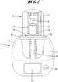
- FIG. 1 shows first an electric motor driven food processor 1, as it is known from the prior art.
- the food processor 1 is designed as a combined cooking-mixing device.
- the food processor 1 has a base unit 2 for receiving a preparation vessel 3.
- a stirrer 4 is arranged, which can be connected to a arranged in the base unit 2 drive means.
- the Base unit 2 furthermore has a display 17 for displaying a selection menu and for displaying information for a user of the food processor 1.
- the food processor 1 has a switch 18 with which, on the one hand, an electric motor of the food processor 1 can be actuated and, on the other hand, a selection of specific preparation steps can be confirmed, the preparation steps possibly having been previously selected via the display 17.
- the base unit 2 further comprises two locking elements 20, which can serve inter alia for locking the preparation vessel 3 with a lid, not shown.
- the locking elements 20 are rotatable in the illustrated arrangement about a horizontal axis.
- the preparation vessel 3 furthermore has a handle 19, on which a user can engage in order to connect the preparation vessel 3 to the base device 2, or to detach them from one another.
- a heating device not shown, is arranged, which serves for heating the preparation vessel 3.
- the heater may be, for example, a thick film heater.
- the preparation vessel 3 may have a temperature sensor which measures a current temperature at the preparation vessel 3.
- FIG. 2 shows the food processor 1 according to FIG. 1 with a distillation device 5 mounted on the preparation vessel 3.
- the distillation device 5 has a connection region 14, namely here a base plate 16 of the distillation device 5, which can be firmly connected to the preparation vessel 3 by means of the locking elements 20.
- the distillation device 5 has a housing 21, which has a vapor absorption device 6 and a condensation device 7 on the inside.
- the vapor absorption device 6 and the condensation device 7 are shown in the illustration FIG. 2 not to be seen.
- the distillation device 5 further comprises a liquid dispensing device 8, which in a receiving area 12 for a collecting vessel 13 from the housing 21 of the Distillation device 5 protrudes.
- the liquid dispensing device 8 is here an end region of a liquid line.
- the collecting vessel 13 is here a glass, which can be removed from the receiving area 12 or introduced into the receiving area 12, in such a way that the collecting vessel 13 is below the liquid dispensing device 8 and discharged liquid can flow into the collecting vessel 13.
- FIG. 3 shows a schematic diagram of a food processor 1 with a distillation device 5, which schematically shows the principle of operation as in FIG. 2 trained food processor 1 reproduces.
- the vapor absorption device 6 which is designed here as a funnel-shaped flow channel 10.
- the flow channel 10 tapers in a direction viewed in the leaf plane from bottom to top. This corresponds to the direction from an inlet opening 15 of the vapor absorption device 6 to the condensation device 7.
- the inlet opening 15 of the distillation device 5 is an opening recessed in the base plate 16. Through this inlet opening 15 steam can get into the steam receiver 6.
- the vapor absorption device 6 has a temperature sensor 9, which is designed here as a semiconductor sensor.
- the measured values of the temperature sensor 9 are read out by means of an evaluation and control device, not shown, of the food processor 1.
- the condensation device 7 adjoins the vapor absorption device 6.
- This has a cooling device 11, which provides a helical flow path, which is guided by a cooled housing.
- the cooling can be done, for example, by means of a Peltier element.
- FIG. 3 a sieve 22 arranged inside the preparation vessel 3 of the food processor 1, which sieve can serve for receiving flavorings during an aromatization of an alcohol base.
- a mash of cereals, fruits or the like is first produced.
- grain is placed in the preparation vessel 3 and comminuted by means of a blade set attached to the agitator 4, i. broken.
- water is added and the mixture is stirred with heating by means of the stirrer 4.
- an enzyme or malt is added. Then the mixture must ferment, which usually takes several days to complete.
- the preparation vessel 3 containing the mash is possibly reconnected to the base unit 2 of the food processor 1 and the distillation device 5, so that the inlet opening 15 of the distillation device 5 lies above the preparation vessel 3.
- the mash is brought to the boil by means of the heating device of the food processor 1, so that steam passes through the inlet opening 15 in the steam receiver 6 of the distillation device 5, flows past the temperature sensor 9 and finally condensed within the condenser 7.
- the temperature sensor 9 measures the temperature of the steam within the steam receiver 6. The measured values are forwarded to the evaluation and control device of the food processor 1 and there with a defined temperature range, which indicates the temperature range between the boiling point of methanol and the boiling point of ethanol.
- Methanol boils at 65 degrees Celsius, while ethanol only boils at 78 degrees Celsius. If the distillation is carried out slowly, a strong methanol-containing fraction is first formed during a run of the distillation process, which is to be disposed of. Once the boiling point of ethanol is reached, the ethanol content increases and the resulting condensate forms the drinkable portion of the alcohol. Once the temperature again drops below the boiling point of ethanol, again increases the relative proportion of methanol, so this fraction should be disposed of again. This is the so-called caster. If the evaluation and control device determines that the temperature of the steam is lower than the boiling temperature of the ethanol, ie lower than 78 degrees Celsius, information is displayed on the display 17 of the base unit 2, which prompts to empty the collecting vessel 13. Alternatively, it could also be provided that an automatically controlled mechanism removes and empties the collecting vessel 13 from the receiving area 12, or the liquid is discharged directly from the liquid dispensing device 8 into a spout. For this purpose, an additional line may be required.
- the steam passes from the vapor receiving device 6 in the condenser 7 and is cooled down there so far that the vapor condenses into a liquid.
- the liquid is then discharged into the collecting vessel 13.
- This is usually aromatized, in turn, the distillation device 5 is used.
- the alcohol base is diluted so much that, for example, an alcohol content of 40 vol .-% is formed.
- the alcohol base is mixed with water.
- the sieve 22 is introduced, which contains flavorings, such as herbs.
- the distillation device 5 is again connected to the preparation vessel 3 and the mixture is brought to a boil.
- the resulting vapor in turn passes through the steam receiver 6, the condenser 7 and the liquid dispensing device 8.
- the condensate is collected within a collecting vessel 13, again in this case the pre-and post-run are separated. In the collecting vessel 13 is then a drinking alcohol with previously set alcohol content.
- the method may further include using a balance of the food processor 1 to weigh corn, water, and the like. Furthermore, a stirring function of the agitator 4 is also advantageously continued during the distillation, in order to prevent, for example, burning.
Landscapes
- Engineering & Computer Science (AREA)
- Chemical & Material Sciences (AREA)
- Organic Chemistry (AREA)
- Food Science & Technology (AREA)
- Chemical Kinetics & Catalysis (AREA)
- Life Sciences & Earth Sciences (AREA)
- Biochemistry (AREA)
- Bioinformatics & Cheminformatics (AREA)
- General Engineering & Computer Science (AREA)
- General Health & Medical Sciences (AREA)
- Genetics & Genomics (AREA)
- Health & Medical Sciences (AREA)
- Wood Science & Technology (AREA)
- Zoology (AREA)
- Mechanical Engineering (AREA)
- Vaporization, Distillation, Condensation, Sublimation, And Cold Traps (AREA)
- Food-Manufacturing Devices (AREA)
Abstract
Description
- Die Erfindung betrifft eine elektromotorisch betriebene Küchenmaschine mit einem einen Elektromotor aufweisenden Basisgerät und einem an dem Basisgerät anordenbaren Zubereitungsgefäß, welchem Zubereitungsgefäß eine Heizeinrichtung und ein Rührwerk zugeordnet sind.
- Des Weiteren betrifft die Erfindung eine Destillationseinrichtung mit einer Dampfaufnahmeeinrichtung, einer Kondensationseinrichtung und einer Flüssigkeitsausgabeeinrichtung.
- Ebenso betrifft die Erfindung auch ein Verfahren zum Betrieb einer Küchenmaschine, welche ein einen Elektromotor aufweisendes Basisgerät und ein an dem Basisgerät anordenbares Zubereitungsgefäß aufweist, wobei dem Zubereitungsgefäß eine Heizeinrichtung und ein Rührwerk zugeordnet sind, wobei eine in dem Zubereitungsgefäß enthaltene Flüssigkeit über deren Siedepunkt hinaus erhitzt wird.
- Elektromotorisch betriebene Küchenmaschinen und eigenständige Destillationseinrichtungen sind im Stand der Technik bekannt.
- Die elektromotorisch betriebenen Küchenmaschinen weisen bspw. ein Zubereitungsgefäß auf, in welches ein Rührwerk durch einen Gefäßboden hineinragt. Das Rührwerk kann bspw. als ein Messersatz mit einer Mehrzahl von Messern ausgebildet sein, um in dem Zubereitungsgefäß befindliches Zubereitungsgut zu zerkleinern und/oder zu rühren. Es ist des Weiteren bekannt, in dem Zubereitungsgefäß befindliches Zubereitungsgut, insbesondere auch Flüssigkeiten, zu erhitzen, wobei das Erhitzen gleichzeitig unter Betrieb des Rührwerkes erfolgen kann.
- Daneben sind im Stand der Technik als selbständige Geräte ausgebildete Destillationseinrichtungen bekannt, welche zur Herstellung von Alkohol, insbesondere Trinkalkohol, dienen. Zur Herstellung von Trinkalkohol werden üblicherweise zwei Destillationsvorgänge durchgeführt. Ein erster Destillationsvorgang dient zur Herstellung einer Alkoholbasis. Ein zweiter Destillationsvorgang dient zur Aromatisierung der Alkoholbasis. Insgesamt sind eine Vielzahl von Herstellungsschritten auszuführen, die teils außerhalb der Destillationseinrichtung und teilweise mittels der Destillationseinrichtung erfolgen.
- Üblicherweise wird zunächst eine Maische hergestellt und gegoren. Hierzu wird Getreide zerkleinert und nach Zugabe von Wasser durch Erhitzen und Rühren verkleistert. Zudem wird ein Enzym oder Malz hinzugegeben. Die so hergestellte Maische muss üblicherweise einige Tage gären, bevor diese weiterverarbeitet werden kann.
- Für den Destillationsvorgang wird die Maische nach abgeschlossener Gärung in ein entsprechendes Gefäß der Destillationseinrichtung gegeben und dort bspw. mittels eines Bunsenbrenners zum Kochen gebracht. Der während des Kochvorgangs entstehende Dampf wird kondensiert, wobei ein Vor- und Nachlauf des Kondensats abgetrennt wird, da dieser bei Unterschreiten einer Siedetemperatur von ca. 78 Grad Celsius einen zu hohen Anteil Methanol enthält, dessen Abbauprodukte schwerwiegende Folgen für den Menschen haben können, angefangen von Kopfschmerzen und Nervenschäden bis hin zu lebensbedrohlichen Folgen. Der unbedenklich genießbare Anteil der so hergestellten Alkoholbasis wird anschließend mit Wasser verdünnt und mit Aromastoffen angereichert. Dies erfolgt wiederum innerhalb der Destillationseinrichtung, wo das Alkohol-Wasser-Gemisch unter Zusatz der Aromastoffe erneut verdampft, kondensiert und wieder aufgegangen wird. Auch dabei wird der Vor- und Nachlauf abgetrennt.
- Nachteilig bei den bekannten Destillationseinrichtungen ist, dass diese lediglich für den Destillationsvorgang verwendet werden können, jedoch nicht zur Herstellung der Maische. Daher werden mehrere separate Geräte benötigt, was zum einen eine Handhabung während der Alkoholherstellung erschwert und zum anderen einen großen Stauraum erfordert. Aufgrund einer benötigten Temperaturregelung ist die Herstellung der Maische zudem sehr aufwändig. Darüber hinaus ist die Temperatur für den Destillationsvorgang einzustellen und zu überwachen, um einerseits ein Anbrennen zu verhindern und andererseits den Anteil des Methanols innerhalb des Alkohols gering zu halten. Daher ist die Herstellung von Alkohol bisher nur besonders kundigen Nutzern zu empfehlen.
- Ausgehend von dem vorgenannten Stand der Technik ist es Aufgabe der Erfindung, die Herstellung von Alkohol einem größeren Nutzerkreis zugänglich zu machen und dafür die zuvor dargestellten Nachteile zu beseitigen.
- Zur Lösung der vorgenannten Aufgabe schlägt die Erfindung zunächst eine elektromotorisch betriebene Küchenmaschine mit einem einen Elektromotor aufweisenden Basisgerät und einem an dem Basisgerät anordenbaren Zubereitungsgefäß vor, wobei dem Zubereitungsgefäß eine Heizeinrichtung und ein Rührwerk zugeordnet sind, wobei die Küchenmaschine des Weiteren eine mit dem Zubereitungsgefäß verbindbare Destillationseinrichtung aufweist, welche eine Dampfaufnahmeeinrichtung, eine Kondensationseinrichtung und eine Flüssigkeitsausgabeeinrichtung aufweist, wobei das Zubereitungsgefäß und die Dampfaufnahmeeinrichtung in verbundenem Zustand von Zubereitungsgefäß und Destillationseinrichtung eine Strömungsverbindung zueinander aufweisen.
- Erfindungsgemäß kombiniert die vorgeschlagene elektromotorisch betriebene Küchenmaschine nun übliche Funktionen wie Rühren und Heizen mit den Funktionen einer Destillationseinrichtung. Die Destillationseinrichtung bildet ein Zubehörteil für die Küchenmaschine, insbesondere einen Aufsatz für das Zubereitungsgefäß. Es empfiehlt sich, dass das Zubereitungsgefäß und die Destillationseinrichtung zur Verbindung miteinander ausgebildet sind, bspw. durch formkorrespondierende Verbindungsbereiche, und ggf. eine Einrichtung zur gegenseitigen Verrastung oder Verriegelung aufweisen. Insbesondere kann zu diesem Zweck eine Verriegelungseinrichtung verwendet werden, die üblicherweise auch zur Verrieglung des Zubereitungsgefäßes mit einem Deckel dient. Alternativ kann es auch vorgesehen sein, dass die Destillationseinrichtung nicht auf das Zubereitungsgefäß aufgesetzt wird, sondern anderweitig mit dem Basisgerät der Küchenmaschine verbunden wird, wobei sichergestellt ist, dass der aus dem Zubereitungsgefäß aufsteigende Dampf in die Dampfaufnahmeeinrichtung der Destillationseinrichtung gelangen kann. Grundsätzlich ist es möglich, dass die Destillationseinrichtung außerhalb der Küchenmaschine angeordnet ist, sofern sichergestellt ist, dass das Zubereitungsgefäß eine Strömungsverbindung zu der Dampfaufnahmeeinrichtung der Destillationseinrichtung aufweist. Durch die erfindungsgemäße Kombination der elektromotorisch betriebenen Küchenmaschine mit einer Destillationseinrichtung kann eine Vielzahl von für die Herstellung von Alkohol auszuführenden Schritten mit der so hergestellten Kombination ausgeführt werden. Dies betrifft insbesondere die Verfahrensschritte zur Herstellung der Maische und zum Durchführen des Brennvorgangs. Im Einzelnen ermöglicht die mit dem Destillationsaufsatz ergänzte Küchenmaschine ein Zerkleinern von Getreide, eine Aufnahme von zugegebenem Wasser, ein Erhitzen, ein Rühren, eine Aufnahme von Enzym oder Malz sowie das Gären innerhalb des Zubereitungsgefäßes. Sofern das Zubereitungsgefäß der Küchenmaschine während der Zeitdauer des Gärprozesses für andere Aufgaben benötigt wird, kann es selbstverständlich vorgesehen sein, dass der Nutzer entweder für den Gärprozess oder für einen anderweitigen Betrieb der Küchenmaschine ein separates Gefäß, insbesondere ein weiteres Zubereitungsgefäß der Küchenmaschine, nutzt. Für einen Brennvorgang kann die Kombination aus Küchenmaschine und Destillationseinrichtung die Verfahrensschritte des Kochens der Maische, Kondensieren des Dampfes und des Auffangens des Kondensats durchführen und ggf. zusätzlich für ein Abtrennen des Vor- und Nachlaufs des Kondensats sorgen. Ggf. kann eine Filtration des Dampfes vorgesehen sein. Die durch die Destillationseinrichtung ergänzte Küchenmaschine ist des Weiteren auch zur Durchführung der Aromatisierung des Alkohols ausgebildet, wobei das Zubereitungsgefäß um einen Siebeinsatz ergänzt wird, mit welchem Aromastoffe, sogenannte "Botanicals", in die in dem Zubereitungsgefäß enthaltene Alkoholbasis eingebracht werden können. Die Aromastoffe können ebenfalls wieder mittels des Rührwerkes der Küchenmaschine zerkleinert werden. Für die Aromatisierung wird die Alkoholbasis mit Wasser verdünnt und ebenfalls wieder mittels der Heizeinrichtung zum Kochen gebracht, wobei der Dampf wie zuvor beschrieben kondensiert und als Flüssigkeit aufgefangen wird. Auch dabei kann ein Vor- und Nachlauf überwacht bzw. abgetrennt werden.
- Insgesamt ist es durch die Ergänzung einer üblichen elektromotorisch betriebenen Küchenmaschine mit einer Destillationseinrichtung im Sinne eines Zubehörteils möglich, einen geführten, überwachten und anwenderfreundlichen Herstellungsprozess für Alkohol durchzuführen. Dabei können zusätzliche Einrichtungen der Küchenmaschine ebenfalls von Nutzen sein, bspw. eine integrierte Waage zur Messung der eingegebenen Zutaten bei der Herstellung der Maische oder auch der vor der Aromatisierung zugegebenen Wassermenge. Des Weiteren ist auch eine der Heizeinrichtung zugeordnete Temperaturmesseinrichtung von Nutzen, um bspw. die aktuelle Temperatur der in dem Zubereitungsgefäß vorhandenen Maische oder Alkoholbasis zu bestimmen. Durch die mittels einer Auswerte- und Steuereinrichtung der Küchenmaschine erlangte Prozesssicherheit ist die Herstellung von Alkohol anwenderunabhängig, sodass die Herstellung von Alkohol einem größeren Nutzerkreis zugänglich wird.
- Es kann vorgesehen sein, dass die Dampfaufnahmeeinrichtung einen Temperatursensor zur Messung der Dampftemperatur aufweist. Gemäß dieser Ausgestaltung weist die Dampfaufnahmeeinrichtung selbst einen Temperatursensor auf, sodass die aktuelle Temperatur des Dampfes innerhalb der Dampfaufnahmeeinrichtung gemessen werden kann. Dies ermöglicht eine besonders genaue Temperaturmessung, um ein übermäßiges Entstehen von Methanol zu verhindern. Die üblicherweise innerhalb der elektromotorisch betriebenen Küchenmaschine vorgesehene Temperaturmesseinrichtung ist gewöhnlich der Heizeinrichtung zugeordnet. Häufig ist diese Temperaturmesseinrichtung ebenso wie die Heizeinrichtung in einen Bodenbereich des Zubereitungsgefäßes integriert. Die dort gemessene Temperatur ist unter Umständen jedoch nicht identisch zu der aktuellen Temperatur des in dem Zubereitungsgefäß enthaltenen Zubereitungsgutes und vor allem nicht zu dem Dampf innerhalb der Dampfaufnahmeeinrichtung. Daher gibt der zusätzlich innerhalb der Dampfaufnahmeeinrichtung angeordnete Temperatursensor - bei alleinigem oder zusätzlichem Betrieb - eine größere Sicherheit über die tatsächliche Temperatur während der Verdampfung. Somit kann genau bestimmt werden, wann die Siedetemperatur von gesundheitsgefährdendem Methanol (65 Grad Celsius) bzw. unbedenklichem Ethanol (78 Grad Celsius) erreicht ist. Besonders bevorzugt befindet sich der Temperatursensor in einem Strömungsweg des Dampfes, wobei die Entfernung zwischen dem Zubereitungsgefäß und dem Messort nicht unnötig weit auseinander liegen sollte bzw. nicht durch kühlende Wandungen und/oder Hindernisse beeinträchtigt sein sollte. Vorzugsweise kann der Dampf den Temperatursensor ohne vorherige Verwirbelung bzw. Strömungsumlenkung erreichen. Der Temperatursensor ist vorzugsweise ein elektrisches oder elektronisches Bauelement, welches ein elektrisches Signal an eine Steuer- und Auswerteeinrichtung der Küchenmaschine übermittelt. Dazu besteht zwischen dem Basisgerät der Küchenmaschine und der Destillationseinrichtung eine entsprechende elektrische Leitung. Der Temperatursensor ist vorteilhaft ein Heißleiter (NTC) oder Kaltleiter (PTC). Des Weiteren sind auch Thermoelemente oder andere möglich. Es kann auch vorgesehen sein, dass mehrere Temperatursensoren innerhalb der Dampfaufnahmeeinrichtung angeordnet sind. Die von der Vielzahl der Temperatursensoren aufgenommenen Messwerte können gemittelt oder auf andere Art und Weise zu einem Temperaturwert verarbeitet werden.
- Es wird vorgeschlagen, dass die Dampfaufnahmeeinrichtung ein eine Strömungsverbindung von dem Zubereitungsgefäß zu der Kondensationseinrichtung bereitstellender Strömungskanal ist. Die Dampfaufnahmeeinrichtung wird vorzugsweise durch einen Strömungskanal gebildet, welcher den Dampf von dem Zubereitungsgefäß zu der Kondensationseinrichtung führt. Vorzugsweise erstreckt sich dieser Strömungskanal in einem geradlinigen Längenbereich in eine Richtung, welche der natürlichen Ausbreitungsrichtung des Dampfes entspricht, d.h. in vertikale Richtung. Der Strömungskanal kann vorzugsweise in einem Gehäuse der Destillationseinrichtung ausgebildet sein, wobei diese in einem Verbindungsbereich zu dem Zubereitungsgefäß der Küchenmaschine bevorzugt eine Eintrittsöffnung zum Einströmen des Dampfes in die Dampfaufnahmeeinrichtung aufweist. Die Destillationseinrichtung bzw. das Zubereitungsgefäß weisen vorteilhaft korrespondierende Verbindungsbereiche zur Herstellung der Strömungsverbindung auf, wobei die Dampfaufnahmeeinrichtung die in dem Verbindungsbereich ausgebildete Eintrittsöffnung aufweist. Besonders vorteilhaft weist die Destillationseinrichtung eine auf das Zubereitungsgefäß aufsetzbare Grundplatte auf, welche eine Eintrittsöffnung in den Strömungskanal bereitstellt.
- Es kann vorgesehen sein, dass sich die Dampfaufnahmeeinrichtung in Strömungsrichtung des Dampfes trichterförmig verjüngt. Im Bereich einer Eintrittsöffnung der Dampfaufnahmeeinrichtung kann die Trichterform noch einen möglichst großen Eintrittsquerschnitt aufweisen, sodass eine möglichst große Dampfmenge in die Dampfaufnahmeeinrichtung einströmen kann, ohne bereits an einem anderen Bereich des Zubereitungsgefäßes zu kondensieren und wieder in die Flüssigkeit zurückzuströmen. In Richtung der Kondensationseinrichtung verjüngt sich die Dampfaufnahmeeinrichtung, wodurch einerseits die Strömungsgeschwindigkeit innerhalb der Dampfaufnahmeeinrichtung erhöht wird und andererseits eine vorteilhafte Verdichtung für den anschließenden Kondensationsvorgang erreicht werden kann.
- Des Weiteren wird vorgeschlagen, dass die Kondensationseinrichtung der Destillationseinrichtung eine Kühleinrichtung aufweist. Insbesondere kann es sich bei der Kühleinrichtung um einen Wärmeübertrager oder ein Peltier-Element handeln. Die Kühleinrichtung kann des Weiteren einen Kühlbehälter aufweisen, einen Ventilator oder andere Mittel, welche geeignet sind, die Temperatur des Dampfes zu reduzieren und eine Kondensation herbeizuführen. Als Wärmeübertrager kommen in diesem Zusammenhang ebenfalls Gegenstromwärmeübertrager, Kühlkreisläufe oder andere infrage. Es empfiehlt sich insbesondere, einen Wärmeübertrager als Kühlschlange auszubilden, sodass eine möglichst große Wechselwirkungsstrecke zur Kondensation des Dampfes zur Verfügung steht.
- Es wird vorgeschlagen, dass die Destillationseinrichtung einen der Flüssigkeitsausgabeeinrichtung zugeordneten Aufnahmebereich zur Anordnung eines Auffanggefäßes aufweist. Die Flüssigkeitsausgabeeinrichtung ist in einem besonders einfachen Fall ein Endbereich eines Strömungskanals, welcher sich in Strömungsrichtung des Kondensats an die Kondensationseinrichtung anschließt. Eine Auslassöffnung der Flüssigkeitsausgabeeinrichtung ist vorzugsweise in Richtung der Gravitationskraft gerichtet, sodass das Kondensat besonders einfach der Schwerkraft folgend aus der Kondensationseinrichtung und durch die Flüssigkeitsausgabeeinrichtung herausströmen kann. Unterhalb der Flüssigkeitsausgabeeinrichtung kann dann innerhalb des Aufnahmebereiches ein Auffanggefäß angeordnet werden, bspw. ein Glas, eine Flasche oder ein sonstiges Gefäß. Je nach der Gestaltung des Gehäuses der Destillationseinrichtung kann der Aufnahmebereich vorzugsweise über dem Zubereitungsgefäß der Küchenmaschine und unterhalb der Flüssigkeitsausgabeeinrichtung angeordnet sein. Besonders vorzugsweise stellt eine Grundplatte der Destillationseinrichtung, welche auf das Zubereitungsgefäß aufgesetzt wird, den Aufnahmebereich zur Verfügung.
- Des Weiteren kann dem Aufnahmebereich eine Einrichtung zum automatischen Entleeren und/oder Entnehmen des Auffanggefäßes zugeordnet sein. Diese Einrichtung ermöglicht gemäß einer besonders bevorzugten Ausführung eine automatische Abtrennung von Vor- und Nachlauf des während der Destillation entstehenden Kondensats. Die Einrichtung weist vorzugsweise einen Mechanismus auf, welcher das Auffanggefäß aus dem Aufnahmebereich entnimmt und diesen entleert, oder eine Öffnung in dem Auffanggefäß freigibt, sodass der Vor- bzw. Nachlauf aus dem Auffanggefäß herausfließen kann oder dergleichen. Durch diese Maßnahme wird sichergestellt, dass der Vor- bzw. Nachlauf auch tatsächlich aus dem Auffanggefäß entfernt wird und nicht in dem Destillat verbleibt, was anderenfalls zu schwerwiegenden gesundheitlichen Schäden führen könnte.
- Des Weiteren wird vorgeschlagen, dass die Küchenmaschine eine Auswerte- und Steuereinrichtung aufweist, welche eingerichtet ist, eine gemessene Temperatur mit einem definierten Temperaturbereich zu vergleichen und im Falle einer Abweichung der gemessenen Temperatur von dem definierten Temperaturbereich eine Information über die Abweichung an einen Nutzer der Küchenmaschine zu übermitteln und/oder ein Entleeren eines Auffanggefäßes zu veranlassen. Mittels der Auswerte- und Steuereinrichtung lässt sich nahezu der gesamte Prozess der Alkoholherstellung überwachen, angefangen von der Herstellung der Maische bis hin zur Durchführung des Destillationsvorgangs. Um sicherzustellen, dass der Nutzer der Küchenmaschine den Vor- und Nachlauf des Kondensats auch tatsächlich aus dem Auffanggefäß entfernt, ist die Auswerte- und Steuereinrichtung eingerichtet, zu ermitteln, welcher Teil des Kondensats abgetrennt werden muss, und welcher als Trinkalkohol verwendet werden darf. In einem einfachen Fall, wird das Entleeren des Auffanggefäßes dem Nutzer der Küchenmaschine überlassen, wobei der Nutzer über die Notwendigkeit des Entleerens informiert wird. Gemäß einer automatisierten Ausführungsform steuert die Auswerte- und Steuereinrichtung eine Einrichtung zum Entleeren und/oder Entnehmen des Auffanggefäßes, um ein Entleeren des Auffanggefäßes auch ohne Zutun des Nutzers zu erreichen. Beide vorgenannten Ausführungsformen dienen dazu, dem Nutzer ein sicheres und gesundheitlich unbedenkliches Produkt zu verschaffen.
- Neben der zuvor erläuterten Küchenmaschine wird mit der Erfindung des Weiteren eine Destillationseinrichtung mit einer Dampfaufnahmeeinrichtung, einer Kondensationseinrichtung und einer Flüssigkeitsausgabeeinrichtung vorgeschlagen, wobei die Destillationseinrichtung einen Verbindungsbereich zur Herstellung einer Strömungsverbindung zu einem Zubereitungsgefäß einer Küchenmaschine aufweist, und wobei die Dampfaufnahmeeinrichtung eine in dem Verbindungsbereich ausgebildete Eintrittsöffnung aufweist. Insbesondere kann der Verbindungsbereich der Destillationseinrichtung eine die Eintrittsöffnung aufweisende Grundplatte aufweisen. Die Destillationseinrichtung dient als ein Zubehörteil für eine zuvor vorgeschlagene Küchenmaschine, wobei die Destillationseinrichtung einen Verbindungsbereich zur Verbindung mit einem Zubereitungsgefäß der Küchenmaschine aufweist. Die Dampfaufnahmeeinrichtung der Destillationseinrichtung ist dabei vorzugsweise so angeordnet und ausgebildet, dass deren Eintrittsöffnung in den Verbindungsbereich zu dem Zubereitungsgefäß ragt und aus dem Zubereitungsgefäß austretender Dampf möglichst unmittelbar in die Dampfaufnahmeeinrichtung gelangen kann. Besonders bevorzugt weist die Destillationseinrichtung eine Grundplatte, bspw. einen Gehäuseboden, auf, in welchem die Eintrittsöffnung ausgebildet ist. Die Grundplatte kann auf einen Rand des Zubereitungsgefäßes aufgesetzt werden, sodass die in der Grundplatte ausgebildete Eintrittsöffnung unmittelbar über dem Zubereitungsgefäß angeordnet ist und der Dampf nach oben in die Destillationseinrichtung aufsteigt.
- Des Weiteren kann die Destillationseinrichtung alle Merkmale aufweisen, welche zuvor auch in Bezug auf die eine Destillationseinrichtung aufweisende Küchenmaschine beschrieben wurden. Dies betrifft insbesondere einen Temperatursensor der Dampfaufnahmeeinrichtung, eine Ausbildung der Dampfaufnahmeeinrichtung als Strömungskanal, eine trichterförmige Ausbildung der Dampfaufnahmeeinrichtung, unterschiedliche Arten von Kondensationseinrichtungen, einen Aufnahmebereich zur Anordnung eines Auffanggefäßes sowie eine Einrichtung zum automatischen Entleeren und/oder Entnehmen des Auffanggefäßes.
- Schließlich wird mit der Erfindung des Weiteren ein Verfahren zum Betrieb einer Küchenmaschine mit einem einen Elektromotor aufweisenden Basisgerät und einem an dem Basisgerät anordenbaren Zubereitungsgefäß vorgeschlagen, welchem Zubereitungsgefäß eine Heizeinrichtung und ein Rührwerk zugeordnet sind, und wobei eine in dem Zubereitungsgefäß enthaltene Flüssigkeit über deren Siedepunkt hinaus erhitzt wird. Erfindungsgemäß wird eine Destillationseinrichtung so mit dem Zubereitungsgefäß verbunden, dass aus dem Zubereitungsgefäß strömender Dampf in die Destillationseinrichtung strömt, wobei der Dampf in einer Dampfaufnahmeeinrichtung aufgenommen wird, anschließend in einer Kondensationseinrichtung kondensiert wird und entstandenes Kondensat mittels einer Flüssigkeitsausgabeeinrichtung ausgegeben wird.
- Im Folgenden wird die Erfindung anhand von Ausführungsbeispielen näher erläutert. Es zeigen:
- Fig. 1
- Eine Küchenmaschine nach dem Stand der Technik,
- Fig. 2
- eine Frontansicht einer Küchenmaschine mit einer auf ein Zubereitungsgefäß aufgesetzten Destillationseinrichtung,
- Fig. 3
- eine Funktionsskizze einer eine Destillationseinrichtung aufweisenden Küchenmaschine in einer teilweise aufgebrochenen Darstellung.
-
Figur 1 zeigt zunächst eine elektromotorisch betriebene Küchenmaschine 1, wie sie aus dem Stand der Technik bekannt ist. Die Küchenmaschine 1 ist als kombiniertes Koch-Mix-Gerät ausgebildet. Die Küchenmaschine 1 verfügt über ein Basisgerät 2 zur Aufnahme eines Zubereitungsgefäßes 3. Innerhalb des Zubereitungsgefäßes 3 ist ein Rührwerk 4 angeordnet, welches mit einer in dem Basisgerät 2 angeordneten Antriebseinrichtung verbunden werden kann. Das Basisgerät 2 weist des Weiteren ein Display 17 zur Anzeige eines Auswahlmenüs sowie zur Anzeige von Informationen für einen Nutzer der Küchenmaschine 1 auf. Des Weiteren verfügt die Küchenmaschine 1 über einen Schalter 18, mit welchem einerseits ein Elektromotor der Küchenmaschine 1 betätigt werden kann und zum anderen eine Auswahl bestimmter Zubereitungsschritte bestätigt werden kann, wobei die Zubereitungsschritte ggf. vorher über das Display 17 ausgewählt wurden. Das Basisgerät 2 weist des Weiteren zwei Verriegelungselemente 20 auf, welche unter anderem zur Verriegelung des Zubereitungsgefäßes 3 mit einem nicht dargestellten Deckel dienen können. Die Verriegelungselemente 20 sind in der dargestellten Anordnung um eine horizontale Achse rotierbar. Das Zubereitungsgefäß 3 weist des Weiteren einen Griff 19 auf, an welchem ein Nutzer angreifen kann, um das Zubereitungsgefäß 3 mit dem Basisgerät 2 zu verbinden, bzw. diese voneinander zu lösen. In einem Bodenbereich des Zubereitungsgefäßes 3 ist des Weiteren eine nicht dargestellte Heizeinrichtung angeordnet, welche zum Heizen des Zubereitungsgefäßes 3 dient. Die Heizeinrichtung kann bspw. eine Dickschichtheizung sein. Des Weiteren kann das Zubereitungsgefäß 3 einen Temperatursensor aufweisen, welcher eine aktuelle Temperatur an dem Zubereitungsgefäß 3 misst. -
Figur 2 zeigt die Küchenmaschine 1 gemäßFigur 1 mit einer auf das Zubereitungsgefäß 3 aufgesetzten Destillationseinrichtung 5. Die Destillationseinrichtung 5 weist einen Verbindungsbereich 14 auf, nämlich hier eine Grundplatte 16 der Destillationseinrichtung 5, welche mittels der Verriegelungselemente 20 fest mit dem Zubereitungsgefäß 3 verbindbar ist. Die Destillationseinrichtung 5 verfügt im Einzelnen über ein Gehäuse 21, welches innenliegend eine Dampfaufnahmeeinrichtung 6 und eine Kondensationseinrichtung 7 aufweist. Die Dampfaufnahmeeinrichtung 6 und die Kondensationseinrichtung 7 sind in der Darstellung gemäßFigur 2 nicht zu sehen. Die Destillationseinrichtung 5 weist des Weiteren eine Flüssigkeitsausgabeeinrichtung 8 auf, welche in einem Aufnahmebereich 12 für ein Auffanggefäß 13 aus dem Gehäuse 21 der Destillationseinrichtung 5 herausragt. Die Flüssigkeitsausgabeeinrichtung 8 ist hier ein Endbereich einer Flüssigkeitsleitung. Das Auffanggefäß 13 ist hier ein Glas, welches aus dem Aufnahmebereich 12 entnommen bzw. in den Aufnahmebereich 12 eingebracht werden kann, und zwar so, dass das Auffanggefäß 13 unterhalb der Flüssigkeitsausgabeeinrichtung 8 steht und ausgegebene Flüssigkeit in das Auffanggefäß 13 strömen kann. -
Figur 3 zeigt eine Prinzipskizze einer Küchenmaschine 1 mit einer Destillationseinrichtung 5, welche schematisch das Funktionsprinzip einer wie inFigur 2 ausgebildeten Küchenmaschine 1 wiedergibt. Im Inneren der Destillationseinrichtung 5, d.h. innerhalb des Gehäuses 21 befindet sich die Dampfaufnahmeeinrichtung 6, welche hier als trichterförmiger Strömungskanal 10 ausgebildet ist. In eine in der Blattebene von unten nach oben betrachtete Richtung verjüngt sich der Strömungskanal 10. Dies entspricht der Richtung von einer Eintrittsöffnung 15 der Dampfaufnahmeeinrichtung 6 bis hin zu der Kondensationseinrichtung 7. Die Eintrittsöffnung 15 der Destillationseinrichtung 5 ist eine in der Grundplatte 16 ausgesparte Öffnung. Durch diese Eintrittsöffnung 15 kann Dampf in die Dampfaufnahmeeinrichtung 6 gelangen. Die Dampfaufnahmeeinrichtung 6 weist einen Temperatursensor 9 auf, welcher hier als Halbleitersensor ausgebildet ist. Die Messwerte des Temperatursensors 9 werden mittels einer nicht dargestellten Auswerte- und Steuereinrichtung der Küchenmaschine 1 ausgelesen. An die Dampfaufnahmeeinrichtung 6 schließt sich die Kondensationseinrichtung 7 an. Diese weist eine Kühleinrichtung 11 auf, die einen schraubenförmigen Strömungsweg bereitstellt, welcher durch ein gekühltes Gehäuse geführt ist. Die Kühlung kann bspw. mittels eines Peltier-Elementes erfolgen. Des Weiteren zeigtFigur 3 ein innerhalb des Zubereitungsgefäßes 3 der Küchenmaschine 1 angeordnetes Sieb 22, welches während einer Aromatisierung einer Alkoholbasis zur Aufnahme von Aromastoffen dienen kann. - Zur Herstellung von Trinkalkohol mittels der Küchenmaschine 1 wird zunächst eine Maische aus Getreide, Obst oder dergleichen hergestellt. Dazu wird bspw. Getreide in das Zubereitungsgefäß 3 gegeben und mittels eines an dem Rührwerk 4 befestigten Messersatzes zerkleinert, d.h. geschrotet. Anschließend wird Wasser zugegeben und das Gemisch unter Erwärmung mittels des Rührwerkes 4 gerührt. Nach dieser sogenannten Verkleisterung wird ein Enzym oder Malz zugegeben. Anschließend muss das Gemisch gären, was üblicherweise mehrere Tage in Anspruch nimmt.
- Nach dem Gärprozess wird das die Maische enthaltende Zubereitungsgefäß 3 ggf. wieder mit dem Basisgerät 2 der Küchenmaschine 1 und der Destillationseinrichtung 5 verbunden, sodass die Eintrittsöffnung 15 der Destillationseinrichtung 5 über dem Zubereitungsgefäß 3 liegt. Anschließend wird die Maische mittels der Heizeinrichtung der Küchenmaschine 1 zum Kochen gebracht, sodass Dampf durch die Eintrittsöffnung 15 in die Dampfaufnahmeeinrichtung 6 der Destillationseinrichtung 5 gelangt, an dem Temperatursensor 9 vorbeiströmt und schließlich innerhalb der Kondensationseinrichtung 7 kondensiert. Das Kondensat gelangt durch die Flüssigkeitsausgabeeinrichtung 8 in das in dem des Aufnahmebereich 12 angeordnete Auffanggefäß 13. Während des Destillationsvorganges misst der Temperatursensor 9 die Temperatur des Dampfes innerhalb der Dampfaufnahmeeinrichtung 6. Die Messwerte werden an die Auswerte- und Steuereinrichtung der Küchenmaschine 1 weitergeleitet und dort mit einem definierten Temperaturbereich verglichen, welcher den Temperaturbereich zwischen der Siedetemperatur von Methanol und der Siedetemperatur von Ethanol angibt. Methanol siedet bei 65 Grad Celsius, während Ethanol erst bei 78 Grad Celsius siedet. Sofern die Destillation langsam durchgeführt wird, wird während eines Vorlaufs des Destillationsvorgangs zuerst eine stark methanolhaltige Fraktion gebildet, die zu entsorgen ist. Sobald der Siedepunkt von Ethanol erreicht ist, steigt der Ethanolanteil und das entstehende Kondensat bildet den trinkbaren Teil des Alkohols. Sobald die Temperatur wieder unter den Siedepunkt des Ethanols absinkt, steigt wiederum der relative Methanolanteil, sodass auch diese Fraktion wieder entsorgt werden sollte. Dies ist der sogenannte Nachlauf. Sofern die Auswerte- und Steuereinrichtung feststellt, dass die Temperatur des Dampfes niedriger ist als die Siedetemperatur des Ethanols, d.h. niedriger als 78 Grad Celsius, wird eine Information auf dem Display 17 des Basisgerätes 2 angezeigt, welche dazu auffordert, das Auffanggefäß 13 zu entleeren. Alternativ könnte auch vorgesehen sein, dass eine automatisch gesteuerte Mechanik das Auffanggefäß 13 aus dem Aufnahmebereich 12 entnimmt und entleert, oder die Flüssigkeit direkt ausgehend von der Flüssigkeitsausgabeeinrichtung 8 in einen Ausguss abgegeben wird. Hierzu ist ggf. eine zusätzliche Leitung erforderlich.
- Während des Destillationsvorgangs gelangt der Dampf von der Dampfaufnahmeeinrichtung 6 in die Kondensationseinrichtung 7 und wird dort soweit heruntergekühlt, dass der Dampf zu einer Flüssigkeit kondensiert. Die Flüssigkeit wird dann in das Auffanggefäß 13 abgegeben. Nach Ende des Destillationsvorgangs, inkl. Entsorgen des Vor- und Nachlaufs, hat man eine trinkbare Alkoholbasis. Diese wird üblicherweise aromatisiert, indem wiederum die Destillationseinrichtung 5 verwendet wird. Zunächst wird die Alkoholbasis soweit verdünnt, dass bspw. ein Alkoholgehalt von 40 Vol.-% entsteht. Hierzu wird die Alkoholbasis mit Wasser gemischt. In das Zubereitungsgefäß 3 der Küchenmaschine 1 wird das Sieb 22 eingebracht, welches Aromastoffe, wie bspw. Kräuter, enthält. Sodann wird die Destillationseinrichtung 5 wieder mit dem Zubereitungsgefäß 3 verbunden und das Gemisch zum Kochen gebracht. Der entstehende Dampf durchläuft wiederum die Dampfaufnahmeeinrichtung 6, die Kondensationseinrichtung 7 und die Flüssigkeitsausgabeeinrichtung 8. Das Kondensat wird innerhalb eines Auffanggefäßes 13 gesammelt, wobei auch hier wiederum der Vor- und Nachlauf abgetrennt werden. In dem Auffanggefäß 13 befindet sich dann ein Trinkalkohol mit zuvor eingestelltem Alkoholgehalt.
- Das Verfahren kann des Weiteren die Verwendung einer Waage der Küchenmaschine 1 zum Abwiegen von Getreide, Wasser und dergleichen beinhalten. Des Weiteren wird auch vorteilhaft eine Rührfunktion des Rührwerkes 4 während der Destillation weitergeführt, um bspw. ein Anbrennen zu verhindern.
-
- 1
- Küchenmaschine
- 2
- Basisgerät
- 3
- Zubereitungsgefäß
- 4
- Rührwerk
- 5
- Destillationseinrichtung
- 6
- Dampfaufnahmeeinrichtung
- 7
- Kondensationseinrichtung
- 8
- Flüssigkeitsausgabeeinrichtung
- 9
- Temperatursensor
- 10
- Strömungskanal
- 11
- Kühleinrichtung
- 12
- Aufnahmebereich
- 13
- Auffanggefäß
- 14
- Verbindungsbereich
- 15
- Eintrittsöffnung
- 16
- Grundplatte
- 17
- Display
- 18
- Schalter
- 19
- Griff
- 20
- Verriegelungselement
- 21
- Gehäuse
- 22
- Sieb
Claims (10)
- Elektromotorisch betriebene Küchenmaschine (1) mit einem einen Elektromotor aufweisenden Basisgerät (2) und einem an dem Basisgerät (2) anordenbaren Zubereitungsgefäß (3), welchem Zubereitungsgefäß (3) eine Heizeinrichtung und ein Rührwerk (4) zugeordnet sind, gekennzeichnet durch eine mit dem Zubereitungsgefäß (3) verbindbare Destillationseinrichtung (5), welche eine Dampfaufnahmeeinrichtung (6), eine Kondensationseinrichtung (7) und eine Flüssigkeitsausgabeeinrichtung (8) aufweist, wobei das Zubereitungsgefäß (3) und die Dampfaufnahmeeinrichtung (6) in verbundenem Zustand von Zubereitungsgefäß (3) und Destillationseinrichtung (5) eine Strömungsverbindung zueinander aufweisen.
- Küchenmaschine (1) nach Anspruch 1, dadurch gekennzeichnet, dass die Dampfaufnahmeeinrichtung (6) einen Temperatursensor (9) zur Messung der Dampftemperatur aufweist.
- Küchenmaschine (1) nach Anspruch 1 oder 2, dadurch gekennzeichnet, dass die Dampfaufnahmeeinrichtung (6) ein eine Strömungsverbindung von dem Zubereitungsgefäß (3) zu der Kondensationseinrichtung (7) bereitstellender Strömungskanal (10) ist.
- Küchenmaschine (1) nach einem der vorhergehenden Ansprüche, dadurch gekennzeichnet, dass sich die Dampfaufnahmeeinrichtung (6) in Strömungsrichtung des Dampfes trichterförmig verjüngt.
- Küchenmaschine (1) nach einem der vorhergehenden Ansprüche, dadurch gekennzeichnet, dass die Kondensationseinrichtung (7) eine Kühleinrichtung (11), insbesondere einen Wärmeübertrager oder ein Peltier-Element, aufweist.
- Küchenmaschine (1) nach einem der vorhergehenden Ansprüche, dadurch gekennzeichnet, dass die Destillationseinrichtung (5) einen der Flüssigkeitsausgabeeinrichtung (8) zugeordneten Aufnahmebereich (12) zur Anordnung eines Auffanggefäßes (13) aufweist.
- Küchenmaschine (1) nach Anspruch 6, dadurch gekennzeichnet, dass dem Aufnahmebereich (12) eine Einrichtung zum automatischen Entleeren und/oder Entnehmen des Auffanggefäßes (13) zugeordnet ist.
- Küchenmaschine (1) nach einem der vorhergehenden Ansprüche, gekennzeichnet durch eine Auswerte- und Steuereinrichtung, welche eingerichtet ist, eine gemessene Temperatur mit einem definierten Temperaturbereich zu vergleichen und im Falle einer Abweichung der gemessenen Temperatur von dem definierten Temperaturbereich eine Information über die Abweichung an einen Nutzer der Küchenmaschine (1) zu übermitteln und/oder ein Entleeren eines Auffanggefäßes (13) zu veranlassen.
- Destillationseinrichtung (5) mit einer Dampfaufnahmeeinrichtung (6), einer Kondensationseinrichtung (7) und einer Flüssigkeitsausgabeeinrichtung (8), dadurch gekennzeichnet, dass die Destillationseinrichtung (5) einen Verbindungsbereich (14) zur Herstellung einer Strömungsverbindung zu einem Zubereitungsgefäß (3) einer Küchenmaschine (1) aufweist, wobei die Dampfaufnahmeeinrichtung (6) eine in dem Verbindungsbereich (14) ausgebildete Eintrittsöffnung (15) aufweist, und wobei der Verbindungsbereich (14) insbesondere eine die Eintrittsöffnung (15) aufweisende Grundplatte (16) aufweist.
- Verfahren zum Betrieb einer Küchenmaschine (1), insbesondere einer Küchenmaschine (1) nach einem der Ansprüche 1 bis 8, mit einem einen Elektromotor aufweisenden Basisgerät (2) und einem an dem Basisgerät (2) anordenbaren Zubereitungsgefäß (3), welchem Zubereitungsgefäß (3) eine Heizeinrichtung und ein Rührwerk (4) zugeordnet sind, wobei eine in dem Zubereitungsgefäß (3) enthaltene Flüssigkeit über deren Siedepunkt hinaus erhitzt wird, dadurch gekennzeichnet, dass eine Destillationseinrichtung (5) so mit dem Zubereitungsgefäß (3) verbunden wird, dass aus dem Zubereitungsgefäß (3) strömender Dampf in die Destillationseinrichtung (5) strömt, wobei der Dampf in einer Dampfaufnahmeeinrichtung (6) aufgenommen wird, anschließend in einer Kondensationseinrichtung (7) kondensiert wird und entstandenes Kondensat mittels einer Flüssigkeitsausgabeeinrichtung (8) ausgegeben wird.
Priority Applications (1)
| Application Number | Priority Date | Filing Date | Title |
|---|---|---|---|
| PL18177320T PL3415062T3 (pl) | 2017-06-16 | 2018-06-12 | Urządzenie kuchenne napędzane elektromotorycznie |
Applications Claiming Priority (1)
| Application Number | Priority Date | Filing Date | Title |
|---|---|---|---|
| DE102017113284.8A DE102017113284A1 (de) | 2017-06-16 | 2017-06-16 | Elektromotorisch betriebene Küchenmaschine |
Publications (2)
| Publication Number | Publication Date |
|---|---|
| EP3415062A1 true EP3415062A1 (de) | 2018-12-19 |
| EP3415062B1 EP3415062B1 (de) | 2021-04-21 |
Family
ID=62620767
Family Applications (1)
| Application Number | Title | Priority Date | Filing Date |
|---|---|---|---|
| EP18177320.1A Active EP3415062B1 (de) | 2017-06-16 | 2018-06-12 | Elektromotorisch betriebene küchenmaschine |
Country Status (6)
| Country | Link |
|---|---|
| US (1) | US10772468B2 (de) |
| EP (1) | EP3415062B1 (de) |
| CN (1) | CN109126174A (de) |
| DE (1) | DE102017113284A1 (de) |
| ES (1) | ES2870551T3 (de) |
| PL (1) | PL3415062T3 (de) |
Families Citing this family (3)
| Publication number | Priority date | Publication date | Assignee | Title |
|---|---|---|---|---|
| AT522365B1 (de) | 2019-05-13 | 2020-10-15 | Innerhuber Johann | Aufsatzbehalter fur eine Kiichenmaschine |
| EP4190212A1 (de) | 2019-10-15 | 2023-06-07 | Vorwerk & Co. Interholding GmbH | Küchenmaschine und verfahren zum betreiben eines heizsystems |
| USD984851S1 (en) * | 2020-07-16 | 2023-05-02 | Harbour Star International Limited | Container |
Citations (3)
| Publication number | Priority date | Publication date | Assignee | Title |
|---|---|---|---|---|
| FR684509A (fr) * | 1929-02-09 | 1930-06-26 | Dispositif pour la cuisson ou l'évaporation par dépression | |
| EP0095797A1 (de) * | 1982-05-27 | 1983-12-07 | Philips Patentverwaltung GmbH | Vorrichtung zum Kondensieren von Kochdämpfen |
| WO2013131731A1 (de) * | 2012-03-07 | 2013-09-12 | HILDENBRAND, Andrea | Garer und mixer |
Family Cites Families (10)
| Publication number | Priority date | Publication date | Assignee | Title |
|---|---|---|---|---|
| DE8803855U1 (de) * | 1988-03-22 | 1988-05-11 | Pietschmann, Helmut, Dipl.-Ing. (FH), 7516 Karlsbad | Aufsatz auf ein Kochgeschirr, zur Herstellung destillierten Wassers |
| JPH045924A (ja) * | 1990-04-24 | 1992-01-09 | Matsushita Electric Ind Co Ltd | 蒸気処理機能付き調理器 |
| TW472785U (en) * | 1998-05-15 | 2002-01-11 | Rong-Kuan Chang | Simple alcohol distiller for home-using |
| US20050223906A1 (en) * | 2004-04-12 | 2005-10-13 | Zhaoxia Xu | Stir-frying Apparatus with Overhead Heating Device |
| DE102010002445A1 (de) * | 2010-02-26 | 2011-09-01 | BSH Bosch und Siemens Hausgeräte GmbH | Haushaltsgerät mit Dampferzeuger |
| CN102408969B (zh) * | 2011-12-08 | 2013-09-11 | 李文庆 | 一种家用自动酿酒机 |
| CN104812453A (zh) * | 2012-06-21 | 2015-07-29 | 阿罗马托尔有限责任公司 | 用于从容器中的植物物质提取精油和水溶胶的蒸馏装置 |
| CN203096041U (zh) * | 2012-12-25 | 2013-07-31 | 宜宾金喜来酒业有限公司 | 气相温度变化在线量质摘酒装置 |
| CN104629980A (zh) * | 2013-11-12 | 2015-05-20 | 孙波 | 家用全自动白酒酿造机 |
| CN103981049B (zh) * | 2014-05-09 | 2016-03-16 | 叶界平 | 家用制酒装置 |
-
2017
- 2017-06-16 DE DE102017113284.8A patent/DE102017113284A1/de not_active Withdrawn
-
2018
- 2018-06-12 PL PL18177320T patent/PL3415062T3/pl unknown
- 2018-06-12 EP EP18177320.1A patent/EP3415062B1/de active Active
- 2018-06-12 ES ES18177320T patent/ES2870551T3/es active Active
- 2018-06-14 US US16/008,206 patent/US10772468B2/en active Active
- 2018-06-14 CN CN201810619758.1A patent/CN109126174A/zh active Pending
Patent Citations (3)
| Publication number | Priority date | Publication date | Assignee | Title |
|---|---|---|---|---|
| FR684509A (fr) * | 1929-02-09 | 1930-06-26 | Dispositif pour la cuisson ou l'évaporation par dépression | |
| EP0095797A1 (de) * | 1982-05-27 | 1983-12-07 | Philips Patentverwaltung GmbH | Vorrichtung zum Kondensieren von Kochdämpfen |
| WO2013131731A1 (de) * | 2012-03-07 | 2013-09-12 | HILDENBRAND, Andrea | Garer und mixer |
Also Published As
| Publication number | Publication date |
|---|---|
| PL3415062T3 (pl) | 2021-10-25 |
| ES2870551T3 (es) | 2021-10-27 |
| US20180360272A1 (en) | 2018-12-20 |
| DE102017113284A1 (de) | 2018-12-20 |
| EP3415062B1 (de) | 2021-04-21 |
| US10772468B2 (en) | 2020-09-15 |
| CN109126174A (zh) | 2019-01-04 |
Similar Documents
| Publication | Publication Date | Title |
|---|---|---|
| EP3415062B1 (de) | Elektromotorisch betriebene küchenmaschine | |
| EP0808108B1 (de) | Wasserlösliches zichorienpulver, verfahren zu seiner herstellung und vorrichtung zur durchführung des verfahrens | |
| DE10111652A1 (de) | Automatischer French-Press Getränke-Bereiter | |
| DE29611088U1 (de) | Vorrichtung zur automatischen Herstellung eines trinkbaren Nahrungs- oder Genußmittels | |
| EP4026460A1 (de) | Speisenzubereitungsgerät zum schneiden von lebensmitteln, zerkleinerungsaufsatz und verfahren | |
| EP3884819A1 (de) | Verfahren zum betreiben eines küchensystems, küchensystem zur zubereitung eines lebensmittels und computerprogrammprodukt | |
| DE102018212162B4 (de) | Zufuhreinrichtung für eine Saftpresse, Küchenmaschine und Saftpresse mit Zufuhreinrichtung | |
| DE212015000057U1 (de) | Tragbares Gerät zur Reduzierung des Alkoholgehalts von Wein und anderen alkoholischen Getränken | |
| EP0600826A1 (de) | Vorrichtung zur Erzeugung von Milchschaum für Cappuccino-Kaffee oder ähnlichen Getränken | |
| DE2745959B2 (de) | Kaffeemaschine | |
| DE29718429U1 (de) | Entsafter | |
| DE602004011122T2 (de) | Vorrichtung zum erwärmen von flüssigkeiten, insbesondere milch | |
| EP3936014B1 (de) | Speisenzubereitungsgerät zum schneiden von lebensmitteln, zerkleinerungsaufsatz und verfahren | |
| CN211785471U (zh) | 一种农产品中农药残留量的检测装置 | |
| DE1617003C3 (de) | Trockenauslassen von tierischem Fett, Knochen und Fleischabfällen und Vorrichtung dafür | |
| CN214373698U (zh) | 农药残留快速检测前处理装置 | |
| CN212731125U (zh) | 一种苍艾中药气雾剂的原液提取装置及原液提取机 | |
| AT503495B1 (de) | Vorrichtung zum zubereiten von getränken | |
| EP3824777A1 (de) | Verfahren und vorrichtung für ein automatisiertes würzen von speisen | |
| CN112485089A (zh) | 农药残留快速检测前处理装置 | |
| WO1998055011A1 (de) | Vorrichtung zur aufbereitung von lebensmitteln | |
| DE602006000137T2 (de) | Küchenmaschine | |
| Olayanju | Design, fabrication and evaluation of a beniseed (Sesamum indicum L.) oil expeller | |
| DE102021110280A1 (de) | Getränkevollautomat und instantbasierte Mixgetränkeherstellung | |
| DE102019108509A1 (de) | Kaffeemaschine |
Legal Events
| Date | Code | Title | Description |
|---|---|---|---|
| PUAI | Public reference made under article 153(3) epc to a published international application that has entered the european phase |
Free format text: ORIGINAL CODE: 0009012 |
|
| STAA | Information on the status of an ep patent application or granted ep patent |
Free format text: STATUS: THE APPLICATION HAS BEEN PUBLISHED |
|
| AK | Designated contracting states |
Kind code of ref document: A1 Designated state(s): AL AT BE BG CH CY CZ DE DK EE ES FI FR GB GR HR HU IE IS IT LI LT LU LV MC MK MT NL NO PL PT RO RS SE SI SK SM TR |
|
| AX | Request for extension of the european patent |
Extension state: BA ME |
|
| STAA | Information on the status of an ep patent application or granted ep patent |
Free format text: STATUS: REQUEST FOR EXAMINATION WAS MADE |
|
| 17P | Request for examination filed |
Effective date: 20190520 |
|
| RBV | Designated contracting states (corrected) |
Designated state(s): AL AT BE BG CH CY CZ DE DK EE ES FI FR GB GR HR HU IE IS IT LI LT LU LV MC MK MT NL NO PL PT RO RS SE SI SK SM TR |
|
| GRAP | Despatch of communication of intention to grant a patent |
Free format text: ORIGINAL CODE: EPIDOSNIGR1 |
|
| STAA | Information on the status of an ep patent application or granted ep patent |
Free format text: STATUS: GRANT OF PATENT IS INTENDED |
|
| RIC1 | Information provided on ipc code assigned before grant |
Ipc: A47J 43/07 20060101AFI20201022BHEP |
|
| INTG | Intention to grant announced |
Effective date: 20201117 |
|
| GRAS | Grant fee paid |
Free format text: ORIGINAL CODE: EPIDOSNIGR3 |
|
| GRAA | (expected) grant |
Free format text: ORIGINAL CODE: 0009210 |
|
| STAA | Information on the status of an ep patent application or granted ep patent |
Free format text: STATUS: THE PATENT HAS BEEN GRANTED |
|
| AK | Designated contracting states |
Kind code of ref document: B1 Designated state(s): AL AT BE BG CH CY CZ DE DK EE ES FI FR GB GR HR HU IE IS IT LI LT LU LV MC MK MT NL NO PL PT RO RS SE SI SK SM TR |
|
| REG | Reference to a national code |
Ref country code: GB Ref legal event code: FG4D Free format text: NOT ENGLISH |
|
| REG | Reference to a national code |
Ref country code: CH Ref legal event code: EP Ref country code: CH Ref legal event code: NV Representative=s name: R.A. EGLI AND CO, PATENTANWAELTE, CH |
|
| REG | Reference to a national code |
Ref country code: DE Ref legal event code: R096 Ref document number: 502018004863 Country of ref document: DE Ref country code: IE Ref legal event code: FG4D Free format text: LANGUAGE OF EP DOCUMENT: GERMAN |
|
| REG | Reference to a national code |
Ref country code: AT Ref legal event code: REF Ref document number: 1383741 Country of ref document: AT Kind code of ref document: T Effective date: 20210515 |
|
| REG | Reference to a national code |
Ref country code: LT Ref legal event code: MG9D |
|
| REG | Reference to a national code |
Ref country code: NL Ref legal event code: MP Effective date: 20210421 |
|
| REG | Reference to a national code |
Ref country code: ES Ref legal event code: FG2A Ref document number: 2870551 Country of ref document: ES Kind code of ref document: T3 Effective date: 20211027 |
|
| PG25 | Lapsed in a contracting state [announced via postgrant information from national office to epo] |
Ref country code: FI Free format text: LAPSE BECAUSE OF FAILURE TO SUBMIT A TRANSLATION OF THE DESCRIPTION OR TO PAY THE FEE WITHIN THE PRESCRIBED TIME-LIMIT Effective date: 20210421 Ref country code: HR Free format text: LAPSE BECAUSE OF FAILURE TO SUBMIT A TRANSLATION OF THE DESCRIPTION OR TO PAY THE FEE WITHIN THE PRESCRIBED TIME-LIMIT Effective date: 20210421 Ref country code: LT Free format text: LAPSE BECAUSE OF FAILURE TO SUBMIT A TRANSLATION OF THE DESCRIPTION OR TO PAY THE FEE WITHIN THE PRESCRIBED TIME-LIMIT Effective date: 20210421 Ref country code: NL Free format text: LAPSE BECAUSE OF FAILURE TO SUBMIT A TRANSLATION OF THE DESCRIPTION OR TO PAY THE FEE WITHIN THE PRESCRIBED TIME-LIMIT Effective date: 20210421 Ref country code: BG Free format text: LAPSE BECAUSE OF FAILURE TO SUBMIT A TRANSLATION OF THE DESCRIPTION OR TO PAY THE FEE WITHIN THE PRESCRIBED TIME-LIMIT Effective date: 20210721 |
|
| PG25 | Lapsed in a contracting state [announced via postgrant information from national office to epo] |
Ref country code: IS Free format text: LAPSE BECAUSE OF FAILURE TO SUBMIT A TRANSLATION OF THE DESCRIPTION OR TO PAY THE FEE WITHIN THE PRESCRIBED TIME-LIMIT Effective date: 20210821 Ref country code: GR Free format text: LAPSE BECAUSE OF FAILURE TO SUBMIT A TRANSLATION OF THE DESCRIPTION OR TO PAY THE FEE WITHIN THE PRESCRIBED TIME-LIMIT Effective date: 20210722 Ref country code: RS Free format text: LAPSE BECAUSE OF FAILURE TO SUBMIT A TRANSLATION OF THE DESCRIPTION OR TO PAY THE FEE WITHIN THE PRESCRIBED TIME-LIMIT Effective date: 20210421 Ref country code: SE Free format text: LAPSE BECAUSE OF FAILURE TO SUBMIT A TRANSLATION OF THE DESCRIPTION OR TO PAY THE FEE WITHIN THE PRESCRIBED TIME-LIMIT Effective date: 20210421 Ref country code: NO Free format text: LAPSE BECAUSE OF FAILURE TO SUBMIT A TRANSLATION OF THE DESCRIPTION OR TO PAY THE FEE WITHIN THE PRESCRIBED TIME-LIMIT Effective date: 20210721 Ref country code: LV Free format text: LAPSE BECAUSE OF FAILURE TO SUBMIT A TRANSLATION OF THE DESCRIPTION OR TO PAY THE FEE WITHIN THE PRESCRIBED TIME-LIMIT Effective date: 20210421 Ref country code: PT Free format text: LAPSE BECAUSE OF FAILURE TO SUBMIT A TRANSLATION OF THE DESCRIPTION OR TO PAY THE FEE WITHIN THE PRESCRIBED TIME-LIMIT Effective date: 20210823 |
|
| REG | Reference to a national code |
Ref country code: DE Ref legal event code: R097 Ref document number: 502018004863 Country of ref document: DE |
|
| PG25 | Lapsed in a contracting state [announced via postgrant information from national office to epo] |
Ref country code: CZ Free format text: LAPSE BECAUSE OF FAILURE TO SUBMIT A TRANSLATION OF THE DESCRIPTION OR TO PAY THE FEE WITHIN THE PRESCRIBED TIME-LIMIT Effective date: 20210421 Ref country code: DK Free format text: LAPSE BECAUSE OF FAILURE TO SUBMIT A TRANSLATION OF THE DESCRIPTION OR TO PAY THE FEE WITHIN THE PRESCRIBED TIME-LIMIT Effective date: 20210421 Ref country code: MC Free format text: LAPSE BECAUSE OF FAILURE TO SUBMIT A TRANSLATION OF THE DESCRIPTION OR TO PAY THE FEE WITHIN THE PRESCRIBED TIME-LIMIT Effective date: 20210421 Ref country code: RO Free format text: LAPSE BECAUSE OF FAILURE TO SUBMIT A TRANSLATION OF THE DESCRIPTION OR TO PAY THE FEE WITHIN THE PRESCRIBED TIME-LIMIT Effective date: 20210421 Ref country code: EE Free format text: LAPSE BECAUSE OF FAILURE TO SUBMIT A TRANSLATION OF THE DESCRIPTION OR TO PAY THE FEE WITHIN THE PRESCRIBED TIME-LIMIT Effective date: 20210421 Ref country code: SK Free format text: LAPSE BECAUSE OF FAILURE TO SUBMIT A TRANSLATION OF THE DESCRIPTION OR TO PAY THE FEE WITHIN THE PRESCRIBED TIME-LIMIT Effective date: 20210421 Ref country code: SM Free format text: LAPSE BECAUSE OF FAILURE TO SUBMIT A TRANSLATION OF THE DESCRIPTION OR TO PAY THE FEE WITHIN THE PRESCRIBED TIME-LIMIT Effective date: 20210421 |
|
| PLBE | No opposition filed within time limit |
Free format text: ORIGINAL CODE: 0009261 |
|
| STAA | Information on the status of an ep patent application or granted ep patent |
Free format text: STATUS: NO OPPOSITION FILED WITHIN TIME LIMIT |
|
| REG | Reference to a national code |
Ref country code: BE Ref legal event code: MM Effective date: 20210630 |
|
| 26N | No opposition filed |
Effective date: 20220124 |
|
| PG25 | Lapsed in a contracting state [announced via postgrant information from national office to epo] |
Ref country code: LU Free format text: LAPSE BECAUSE OF NON-PAYMENT OF DUE FEES Effective date: 20210612 |
|
| PG25 | Lapsed in a contracting state [announced via postgrant information from national office to epo] |
Ref country code: IE Free format text: LAPSE BECAUSE OF NON-PAYMENT OF DUE FEES Effective date: 20210612 |
|
| PG25 | Lapsed in a contracting state [announced via postgrant information from national office to epo] |
Ref country code: IS Free format text: LAPSE BECAUSE OF FAILURE TO SUBMIT A TRANSLATION OF THE DESCRIPTION OR TO PAY THE FEE WITHIN THE PRESCRIBED TIME-LIMIT Effective date: 20210821 Ref country code: AL Free format text: LAPSE BECAUSE OF FAILURE TO SUBMIT A TRANSLATION OF THE DESCRIPTION OR TO PAY THE FEE WITHIN THE PRESCRIBED TIME-LIMIT Effective date: 20210421 |
|
| PG25 | Lapsed in a contracting state [announced via postgrant information from national office to epo] |
Ref country code: BE Free format text: LAPSE BECAUSE OF NON-PAYMENT OF DUE FEES Effective date: 20210630 |
|
| P01 | Opt-out of the competence of the unified patent court (upc) registered |
Effective date: 20230517 |
|
| PG25 | Lapsed in a contracting state [announced via postgrant information from national office to epo] |
Ref country code: CY Free format text: LAPSE BECAUSE OF FAILURE TO SUBMIT A TRANSLATION OF THE DESCRIPTION OR TO PAY THE FEE WITHIN THE PRESCRIBED TIME-LIMIT Effective date: 20210421 |
|
| PG25 | Lapsed in a contracting state [announced via postgrant information from national office to epo] |
Ref country code: HU Free format text: LAPSE BECAUSE OF FAILURE TO SUBMIT A TRANSLATION OF THE DESCRIPTION OR TO PAY THE FEE WITHIN THE PRESCRIBED TIME-LIMIT; INVALID AB INITIO Effective date: 20180612 |
|
| PG25 | Lapsed in a contracting state [announced via postgrant information from national office to epo] |
Ref country code: MK Free format text: LAPSE BECAUSE OF FAILURE TO SUBMIT A TRANSLATION OF THE DESCRIPTION OR TO PAY THE FEE WITHIN THE PRESCRIBED TIME-LIMIT Effective date: 20210421 |
|
| PG25 | Lapsed in a contracting state [announced via postgrant information from national office to epo] |
Ref country code: TR Free format text: LAPSE BECAUSE OF FAILURE TO SUBMIT A TRANSLATION OF THE DESCRIPTION OR TO PAY THE FEE WITHIN THE PRESCRIBED TIME-LIMIT Effective date: 20210421 |
|
| REG | Reference to a national code |
Ref country code: AT Ref legal event code: MM01 Ref document number: 1383741 Country of ref document: AT Kind code of ref document: T Effective date: 20230612 |
|
| PG25 | Lapsed in a contracting state [announced via postgrant information from national office to epo] |
Ref country code: MT Free format text: LAPSE BECAUSE OF FAILURE TO SUBMIT A TRANSLATION OF THE DESCRIPTION OR TO PAY THE FEE WITHIN THE PRESCRIBED TIME-LIMIT Effective date: 20210421 |
|
| PG25 | Lapsed in a contracting state [announced via postgrant information from national office to epo] |
Ref country code: AT Free format text: LAPSE BECAUSE OF NON-PAYMENT OF DUE FEES Effective date: 20230612 |
|
| PG25 | Lapsed in a contracting state [announced via postgrant information from national office to epo] |
Ref country code: AT Free format text: LAPSE BECAUSE OF NON-PAYMENT OF DUE FEES Effective date: 20230612 |
|
| PGFP | Annual fee paid to national office [announced via postgrant information from national office to epo] |
Ref country code: PL Payment date: 20250529 Year of fee payment: 8 Ref country code: DE Payment date: 20250618 Year of fee payment: 8 |
|
| PGFP | Annual fee paid to national office [announced via postgrant information from national office to epo] |
Ref country code: GB Payment date: 20250620 Year of fee payment: 8 |
|
| PGFP | Annual fee paid to national office [announced via postgrant information from national office to epo] |
Ref country code: FR Payment date: 20250626 Year of fee payment: 8 |
|
| PGFP | Annual fee paid to national office [announced via postgrant information from national office to epo] |
Ref country code: ES Payment date: 20250718 Year of fee payment: 8 |
|
| PGFP | Annual fee paid to national office [announced via postgrant information from national office to epo] |
Ref country code: IT Payment date: 20250630 Year of fee payment: 8 |
|
| PGFP | Annual fee paid to national office [announced via postgrant information from national office to epo] |
Ref country code: CH Payment date: 20250701 Year of fee payment: 8 |
|
| PGFP | Annual fee paid to national office [announced via postgrant information from national office to epo] |
Ref country code: AT Payment date: 20260410 Year of fee payment: 5 |