EP3414756B1 - Akustischer absorber, akustische wand und verfahren zur konstruktion und herstellung - Google Patents
Akustischer absorber, akustische wand und verfahren zur konstruktion und herstellung Download PDFInfo
- Publication number
- EP3414756B1 EP3414756B1 EP17706702.2A EP17706702A EP3414756B1 EP 3414756 B1 EP3414756 B1 EP 3414756B1 EP 17706702 A EP17706702 A EP 17706702A EP 3414756 B1 EP3414756 B1 EP 3414756B1
- Authority
- EP
- European Patent Office
- Prior art keywords
- wafer
- frequency
- neck
- acoustic
- absorber
- Prior art date
- Legal status (The legal status is an assumption and is not a legal conclusion. Google has not performed a legal analysis and makes no representation as to the accuracy of the status listed.)
- Active
Links
- 238000004519 manufacturing process Methods 0.000 title claims description 16
- 238000000034 method Methods 0.000 title claims description 14
- 239000006098 acoustic absorber Substances 0.000 title claims description 8
- 238000013461 design Methods 0.000 title description 4
- 210000003739 neck Anatomy 0.000 claims description 82
- 239000006096 absorbing agent Substances 0.000 claims description 58
- 238000010521 absorption reaction Methods 0.000 claims description 54
- 239000000725 suspension Substances 0.000 claims description 54
- 239000000463 material Substances 0.000 claims description 18
- 239000012528 membrane Substances 0.000 claims description 18
- 230000002093 peripheral effect Effects 0.000 claims description 8
- 229910052710 silicon Inorganic materials 0.000 claims description 7
- 239000010703 silicon Substances 0.000 claims description 7
- 238000005520 cutting process Methods 0.000 claims description 5
- 229910045601 alloy Inorganic materials 0.000 claims description 4
- 239000000956 alloy Substances 0.000 claims description 4
- 239000004033 plastic Substances 0.000 claims description 4
- 229920000642 polymer Polymers 0.000 claims description 4
- 229910000831 Steel Inorganic materials 0.000 claims description 3
- 229910052782 aluminium Inorganic materials 0.000 claims description 3
- XAGFODPZIPBFFR-UHFFFAOYSA-N aluminium Chemical compound [Al] XAGFODPZIPBFFR-UHFFFAOYSA-N 0.000 claims description 3
- 230000000694 effects Effects 0.000 claims description 3
- 229920003023 plastic Polymers 0.000 claims description 3
- 239000010959 steel Substances 0.000 claims description 3
- RTAQQCXQSZGOHL-UHFFFAOYSA-N Titanium Chemical compound [Ti] RTAQQCXQSZGOHL-UHFFFAOYSA-N 0.000 claims description 2
- PNEYBMLMFCGWSK-UHFFFAOYSA-N aluminium oxide Inorganic materials [O-2].[O-2].[O-2].[Al+3].[Al+3] PNEYBMLMFCGWSK-UHFFFAOYSA-N 0.000 claims description 2
- 230000000903 blocking effect Effects 0.000 claims description 2
- 230000008569 process Effects 0.000 claims description 2
- 239000010453 quartz Substances 0.000 claims description 2
- VYPSYNLAJGMNEJ-UHFFFAOYSA-N silicon dioxide Inorganic materials O=[Si]=O VYPSYNLAJGMNEJ-UHFFFAOYSA-N 0.000 claims description 2
- 239000010936 titanium Substances 0.000 claims description 2
- 229910052719 titanium Inorganic materials 0.000 claims description 2
- 235000012431 wafers Nutrition 0.000 claims 26
- 239000004411 aluminium Substances 0.000 claims 1
- 239000008188 pellet Substances 0.000 description 34
- 238000006073 displacement reaction Methods 0.000 description 19
- 235000010603 pastilles Nutrition 0.000 description 15
- 230000009467 reduction Effects 0.000 description 12
- 239000003826 tablet Substances 0.000 description 9
- XUIMIQQOPSSXEZ-UHFFFAOYSA-N Silicon Chemical compound [Si] XUIMIQQOPSSXEZ-UHFFFAOYSA-N 0.000 description 8
- 230000005520 electrodynamics Effects 0.000 description 8
- 230000000737 periodic effect Effects 0.000 description 7
- 238000010586 diagram Methods 0.000 description 5
- 230000003252 repetitive effect Effects 0.000 description 5
- 241000256815 Apocrita Species 0.000 description 4
- 230000006978 adaptation Effects 0.000 description 4
- 229920001971 elastomer Polymers 0.000 description 4
- 230000006872 improvement Effects 0.000 description 4
- 229910052751 metal Inorganic materials 0.000 description 4
- 239000002184 metal Substances 0.000 description 4
- -1 or in addition Substances 0.000 description 4
- 238000012360 testing method Methods 0.000 description 4
- 230000003213 activating effect Effects 0.000 description 3
- 230000002238 attenuated effect Effects 0.000 description 3
- 239000000806 elastomer Substances 0.000 description 3
- 238000005516 engineering process Methods 0.000 description 3
- 238000002474 experimental method Methods 0.000 description 3
- 239000006260 foam Substances 0.000 description 3
- 230000004048 modification Effects 0.000 description 3
- 238000012986 modification Methods 0.000 description 3
- 230000000717 retained effect Effects 0.000 description 3
- 238000001228 spectrum Methods 0.000 description 3
- 239000003351 stiffener Substances 0.000 description 3
- 241000239290 Araneae Species 0.000 description 2
- 239000004971 Cross linker Substances 0.000 description 2
- 239000004698 Polyethylene Substances 0.000 description 2
- 230000002745 absorbent Effects 0.000 description 2
- 239000002250 absorbent Substances 0.000 description 2
- 238000005452 bending Methods 0.000 description 2
- 230000015572 biosynthetic process Effects 0.000 description 2
- 238000004364 calculation method Methods 0.000 description 2
- 239000002131 composite material Substances 0.000 description 2
- 230000007423 decrease Effects 0.000 description 2
- 230000008021 deposition Effects 0.000 description 2
- 239000004205 dimethyl polysiloxane Substances 0.000 description 2
- 235000013870 dimethyl polysiloxane Nutrition 0.000 description 2
- 239000013013 elastic material Substances 0.000 description 2
- 238000009434 installation Methods 0.000 description 2
- 230000010354 integration Effects 0.000 description 2
- 229920000126 latex Polymers 0.000 description 2
- 239000004816 latex Substances 0.000 description 2
- 229920000435 poly(dimethylsiloxane) Polymers 0.000 description 2
- 229920000573 polyethylene Polymers 0.000 description 2
- 229920006254 polymer film Polymers 0.000 description 2
- 239000011347 resin Substances 0.000 description 2
- 229920005989 resin Polymers 0.000 description 2
- 238000003786 synthesis reaction Methods 0.000 description 2
- 229910018072 Al 2 O 3 Inorganic materials 0.000 description 1
- 229910000906 Bronze Inorganic materials 0.000 description 1
- 229920000271 Kevlar® Polymers 0.000 description 1
- 241001417494 Sciaenidae Species 0.000 description 1
- 229910001069 Ti alloy Inorganic materials 0.000 description 1
- QJVKUMXDEUEQLH-UHFFFAOYSA-N [B].[Fe].[Nd] Chemical compound [B].[Fe].[Nd] QJVKUMXDEUEQLH-UHFFFAOYSA-N 0.000 description 1
- 230000004913 activation Effects 0.000 description 1
- 239000011149 active material Substances 0.000 description 1
- 239000000654 additive Substances 0.000 description 1
- 230000000996 additive effect Effects 0.000 description 1
- 238000000149 argon plasma sintering Methods 0.000 description 1
- 239000010974 bronze Substances 0.000 description 1
- 239000011111 cardboard Substances 0.000 description 1
- 238000003486 chemical etching Methods 0.000 description 1
- 238000006243 chemical reaction Methods 0.000 description 1
- KUNSUQLRTQLHQQ-UHFFFAOYSA-N copper tin Chemical compound [Cu].[Sn] KUNSUQLRTQLHQQ-UHFFFAOYSA-N 0.000 description 1
- 230000001066 destructive effect Effects 0.000 description 1
- 238000009760 electrical discharge machining Methods 0.000 description 1
- 239000004744 fabric Substances 0.000 description 1
- 239000011554 ferrofluid Substances 0.000 description 1
- 239000012530 fluid Substances 0.000 description 1
- 239000011888 foil Substances 0.000 description 1
- 230000005484 gravity Effects 0.000 description 1
- 239000007943 implant Substances 0.000 description 1
- 238000009776 industrial production Methods 0.000 description 1
- 230000000977 initiatory effect Effects 0.000 description 1
- 238000009413 insulation Methods 0.000 description 1
- 239000004761 kevlar Substances 0.000 description 1
- 238000003698 laser cutting Methods 0.000 description 1
- 239000007788 liquid Substances 0.000 description 1
- 239000000314 lubricant Substances 0.000 description 1
- 238000005259 measurement Methods 0.000 description 1
- 239000003607 modifier Substances 0.000 description 1
- 229910021421 monocrystalline silicon Inorganic materials 0.000 description 1
- 229910001172 neodymium magnet Inorganic materials 0.000 description 1
- CXQXSVUQTKDNFP-UHFFFAOYSA-N octamethyltrisiloxane Chemical compound C[Si](C)(C)O[Si](C)(C)O[Si](C)(C)C CXQXSVUQTKDNFP-UHFFFAOYSA-N 0.000 description 1
- 230000003534 oscillatory effect Effects 0.000 description 1
- 239000011087 paperboard Substances 0.000 description 1
- 238000004987 plasma desorption mass spectroscopy Methods 0.000 description 1
- 238000001020 plasma etching Methods 0.000 description 1
- 229920006255 plastic film Polymers 0.000 description 1
- 230000010287 polarization Effects 0.000 description 1
- 238000006116 polymerization reaction Methods 0.000 description 1
- 229920001296 polysiloxane Polymers 0.000 description 1
- 229920001343 polytetrafluoroethylene Polymers 0.000 description 1
- 239000004810 polytetrafluoroethylene Substances 0.000 description 1
- 239000011148 porous material Substances 0.000 description 1
- 230000001737 promoting effect Effects 0.000 description 1
- 238000011160 research Methods 0.000 description 1
- 230000004044 response Effects 0.000 description 1
- 239000005060 rubber Substances 0.000 description 1
- 238000007789 sealing Methods 0.000 description 1
- 239000000126 substance Substances 0.000 description 1
- 239000000758 substrate Substances 0.000 description 1
- 230000008719 thickening Effects 0.000 description 1
- XLYOFNOQVPJJNP-UHFFFAOYSA-N water Substances O XLYOFNOQVPJJNP-UHFFFAOYSA-N 0.000 description 1
Images


Classifications
-
- H—ELECTRICITY
- H04—ELECTRIC COMMUNICATION TECHNIQUE
- H04R—LOUDSPEAKERS, MICROPHONES, GRAMOPHONE PICK-UPS OR LIKE ACOUSTIC ELECTROMECHANICAL TRANSDUCERS; DEAF-AID SETS; PUBLIC ADDRESS SYSTEMS
- H04R1/00—Details of transducers, loudspeakers or microphones
- H04R1/20—Arrangements for obtaining desired frequency or directional characteristics
- H04R1/22—Arrangements for obtaining desired frequency or directional characteristics for obtaining desired frequency characteristic only
- H04R1/28—Transducer mountings or enclosures modified by provision of mechanical or acoustic impedances, e.g. resonator, damping means
- H04R1/2869—Reduction of undesired resonances, i.e. standing waves within enclosure, or of undesired vibrations, i.e. of the enclosure itself
- H04R1/2892—Mountings or supports for transducers
- H04R1/2896—Mountings or supports for transducers for loudspeaker transducers
-
- E—FIXED CONSTRUCTIONS
- E04—BUILDING
- E04B—GENERAL BUILDING CONSTRUCTIONS; WALLS, e.g. PARTITIONS; ROOFS; FLOORS; CEILINGS; INSULATION OR OTHER PROTECTION OF BUILDINGS
- E04B1/00—Constructions in general; Structures which are not restricted either to walls, e.g. partitions, or floors or ceilings or roofs
- E04B1/62—Insulation or other protection; Elements or use of specified material therefor
- E04B1/74—Heat, sound or noise insulation, absorption, or reflection; Other building methods affording favourable thermal or acoustical conditions, e.g. accumulating of heat within walls
- E04B1/82—Heat, sound or noise insulation, absorption, or reflection; Other building methods affording favourable thermal or acoustical conditions, e.g. accumulating of heat within walls specifically with respect to sound only
- E04B1/8209—Heat, sound or noise insulation, absorption, or reflection; Other building methods affording favourable thermal or acoustical conditions, e.g. accumulating of heat within walls specifically with respect to sound only sound absorbing devices
-
- E—FIXED CONSTRUCTIONS
- E04—BUILDING
- E04B—GENERAL BUILDING CONSTRUCTIONS; WALLS, e.g. PARTITIONS; ROOFS; FLOORS; CEILINGS; INSULATION OR OTHER PROTECTION OF BUILDINGS
- E04B1/00—Constructions in general; Structures which are not restricted either to walls, e.g. partitions, or floors or ceilings or roofs
- E04B1/62—Insulation or other protection; Elements or use of specified material therefor
- E04B1/74—Heat, sound or noise insulation, absorption, or reflection; Other building methods affording favourable thermal or acoustical conditions, e.g. accumulating of heat within walls
- E04B1/82—Heat, sound or noise insulation, absorption, or reflection; Other building methods affording favourable thermal or acoustical conditions, e.g. accumulating of heat within walls specifically with respect to sound only
- E04B1/84—Sound-absorbing elements
- E04B1/86—Sound-absorbing elements slab-shaped
-
- G—PHYSICS
- G10—MUSICAL INSTRUMENTS; ACOUSTICS
- G10K—SOUND-PRODUCING DEVICES; METHODS OR DEVICES FOR PROTECTING AGAINST, OR FOR DAMPING, NOISE OR OTHER ACOUSTIC WAVES IN GENERAL; ACOUSTICS NOT OTHERWISE PROVIDED FOR
- G10K11/00—Methods or devices for transmitting, conducting or directing sound in general; Methods or devices for protecting against, or for damping, noise or other acoustic waves in general
- G10K11/16—Methods or devices for protecting against, or for damping, noise or other acoustic waves in general
-
- H—ELECTRICITY
- H04—ELECTRIC COMMUNICATION TECHNIQUE
- H04R—LOUDSPEAKERS, MICROPHONES, GRAMOPHONE PICK-UPS OR LIKE ACOUSTIC ELECTROMECHANICAL TRANSDUCERS; DEAF-AID SETS; PUBLIC ADDRESS SYSTEMS
- H04R9/00—Transducers of moving-coil, moving-strip, or moving-wire type
- H04R9/06—Loudspeakers
-
- E—FIXED CONSTRUCTIONS
- E04—BUILDING
- E04B—GENERAL BUILDING CONSTRUCTIONS; WALLS, e.g. PARTITIONS; ROOFS; FLOORS; CEILINGS; INSULATION OR OTHER PROTECTION OF BUILDINGS
- E04B1/00—Constructions in general; Structures which are not restricted either to walls, e.g. partitions, or floors or ceilings or roofs
- E04B1/62—Insulation or other protection; Elements or use of specified material therefor
- E04B1/74—Heat, sound or noise insulation, absorption, or reflection; Other building methods affording favourable thermal or acoustical conditions, e.g. accumulating of heat within walls
- E04B1/82—Heat, sound or noise insulation, absorption, or reflection; Other building methods affording favourable thermal or acoustical conditions, e.g. accumulating of heat within walls specifically with respect to sound only
- E04B1/84—Sound-absorbing elements
- E04B2001/8423—Tray or frame type panels or blocks, with or without acoustical filling
- E04B2001/8428—Tray or frame type panels or blocks, with or without acoustical filling containing specially shaped acoustical bodies, e.g. funnels, egg-crates, fanfolds
-
- E—FIXED CONSTRUCTIONS
- E04—BUILDING
- E04B—GENERAL BUILDING CONSTRUCTIONS; WALLS, e.g. PARTITIONS; ROOFS; FLOORS; CEILINGS; INSULATION OR OTHER PROTECTION OF BUILDINGS
- E04B1/00—Constructions in general; Structures which are not restricted either to walls, e.g. partitions, or floors or ceilings or roofs
- E04B1/62—Insulation or other protection; Elements or use of specified material therefor
- E04B1/74—Heat, sound or noise insulation, absorption, or reflection; Other building methods affording favourable thermal or acoustical conditions, e.g. accumulating of heat within walls
- E04B1/82—Heat, sound or noise insulation, absorption, or reflection; Other building methods affording favourable thermal or acoustical conditions, e.g. accumulating of heat within walls specifically with respect to sound only
- E04B1/84—Sound-absorbing elements
- E04B2001/8457—Solid slabs or blocks
- E04B2001/8476—Solid slabs or blocks with acoustical cavities, with or without acoustical filling
- E04B2001/848—Solid slabs or blocks with acoustical cavities, with or without acoustical filling the cavities opening onto the face of the element
- E04B2001/8485—Solid slabs or blocks with acoustical cavities, with or without acoustical filling the cavities opening onto the face of the element the opening being restricted, e.g. forming Helmoltz resonators
Definitions
- the invention provides a passive sound absorber, comprising a cavity open towards the outside on the side where the sound wave is incident through a neck passing through the front wall to form a Helmholtz resonator for a first frequency.
- this absorber further comprises at least one movable element, or pellet, suspended or held by suspensions in a position obstructing said neck in a leaktight manner.
- the relative stiffness of the suspensions and of the pad is determined so that the assembly formed by the pad and the suspension arms vibrates according to a "piston" type resonance mode at a second frequency different from the first frequency, and notably lower than it, thus achieving an absorption for this second frequency or frequency range.
- This second frequency is located between the first frequency and a third frequency which is that of the whole of the tablet with its suspension when it is measured in the open air.
- a hybrid version includes a controlled coil to adapt the acoustic impedance of the absorber.
- the invention further provides an acoustic wall comprising a plurality of such absorbers produced by a repetitive structure opening out through perforations each receiving such a pellet.
- Noise is an important source of noise pollution. Passive noise reduction solutions such as foam are widely used in most fields.
- Passive solutions using Helmholtz resonators are also widely applied, in particular to avoid reflections which can be sources of acoustic resonances.
- acoustic vases were placed under the stands of Greek or Roman theaters in order to avoid reflections and improve the acoustics of the building.
- the size and shape of the vase were adjusted in order to obtain a resonant system which made it possible to suppress the reflection of the acoustic waves on the stands.
- similar devices are present in the nacelles of aircraft reactors.
- resonant cavity This system is based on the acoustic resonance of the cavity, which can be described as "resonant cavity”.
- the functioning of resonant cavities was theorized much later and today bears the name of "Helmholtz resonator”.
- the Helmholtz resonator 1 is an open air cavity comparable to an open bottle composed of a neck 11 and a rear volume 10.
- this cavity 10 is enclosed in side walls 19, a wall of bottom 18 and a front wall 17, and is only open in a direction A11 through an orifice passing through the front wall 17.
- This orifice forms a "neck" 11 having a certain length and thus delimiting a volume, which is defined by the length L11 of the neck and its opening surface A11, for example a circular surface thus forming a cylindrical neck.
- the volume of the neck 11 and the rear volume 10 of the cavity are comparable respectively to the mass and the stiffness of a mechanical oscillatory system with a degree of freedom.
- the absorption is then produced by conversion of the pressure variation from the acoustic wave into displacement of a fluid.
- the energy of the acoustic wave at the resonant frequency of the resonator is then transferred to the resonant system.
- noise reduction device choice of a noise reduction device is made according to the cost of the envisaged solution, the size but also other constraints such as the operating temperature, as in the case of noise reduction of reactor plane.
- cavities tuned in Helmholtz resonators are currently implanted on the walls of the reactors, as illustrated in FIGURE 2 .
- These cavities 10 are manufactured using plates 20 forming a periodic structure, in the form of a honeycomb in the case of the Figure 2 .
- Such a plate 20 is enclosed between a full rear plate 28 and a front plate 27. The latter is pierced with holes 11 opening into the cells 10, and which each constitute the neck of a resonator 1.
- This structure makes it possible to conform the 'assembly obtained 2 to the shape of the outer wall of the reactor and to ensure its rigidity.
- An object of the invention is to overcome the drawbacks of the prior art.
- the present invention seeks improvements in particular in terms of absorption performance, as well as in width and positioning of the attenuated frequency ranges. It is also sought to improve the flexibility of implementation and adaptation, that is to say including the flexibility of design with respect to the frequencies to be absorbed, in spectrum width and towards the low frequencies. . It is also sought after cost, simplicity and reliability, as well as resistance to external constraints.
- the invention provides an acoustic absorber device, in particular a passive absorber, comprising a rigid enclosure delimiting a cavity, which is closed on its periphery except in a so-called entry direction (generally single) through which this cavity opens outwards. .
- This outlet is made by at least one orifice passing through a so-called front wall, rigid and of a determined thickness, thus forming at least one neck having a determined opening surface and a determined length.
- the neck is thus defined as having a shape and a fixed position, and constant dimensions.
- the dimensions of said enclosure and said neck are determined, typically by the volume of the enclosure, as well as the surface and the length of the neck, to form together a Helmholtz resonator for an incident wave of a first frequency or frequency range , called natural frequency.
- this neck is distributed in several orifices opening onto the same cavity so that the assembly behaves like a single Helmholtz resonator, typically orifices opening out substantially in the same direction or in substantially parallel directions, for example forming between them an angle of less than 30 ° or even less than 15 °.
- this absorber further comprises at least one movable element, here called a pellet, suspended from said enclosure by one or more mechanical connections, here called suspensions (for example by a continuity of material (x)) in an obstructing position at least partially said at least one neck, in a leaktight manner over at least part of its travel. That is to say that there remains a leakage section over at least part of the displacement travel, or even over the whole of this travel.
- at least one movable element here called a pellet
- suspensions for example by a continuity of material (x)
- a leakage section remains permanently.
- the movable element may or may not remain inside the neck over its entire travel.
- the movable element can also obstruct the cavity in a sealed manner when it is located inside the neck, but have part of its travel on which a leakage section appears, for example at two ends of its travel or at least one of them.
- the stiffness of the suspensions and the stiffness of the pellet are determined in their combination (or in their ratio) so that said pellet vibrates according to a resonance mode in a displacement of the "piston" type according to the direction of the incident wave, at a second frequency or frequency range different from the first frequency (and in particular lower), thus achieving absorption for this second frequency or frequency range.
- the patch can be positioned in different locations relative to the neck, either inside the neck or in front of it, on the inside or outside, and in a way that may vary during of its displacement.
- the suspended tablet is determined in such a way that the suspension of the absorber, tested or calculated once loaded, that is to say with the tablet but in the open air outside the cavity, has a resonance at a third frequency which is different from the first frequency.
- the second frequency obtained by assembling the cavity and the suspended pellet, will thus be located between the first frequency (ie the Helmholtz frequency of the cavity) and the third frequency (that of the suspended pellet, measured at the outdoors).
- the third frequency is lower than the first frequency.
- the second frequency, located between the two, is therefore also lower than the Helmholtz frequency.
- the third frequency is higher than the first frequency.
- the second frequency, located between the two, is therefore also higher than the Helmholtz frequency.
- the patch occupies a section of at least 80% of the section of the neck.
- this piece has a part moving in piston mode and forming said pellet, over a section of at least 80% of the section of the neck.
- Such a displacement in "piston mode” is here defined, for a two-dimensional object, as a displacement perpendicular to its average surface in which the object has a deformation which is very slight or even negligible compared to this displacement. That is to say with a simultaneous displacement of all its parts in the same direction and at identical or very close speeds, and therefore with little or no bending.
- Such a displacement in "piston” mode is for example different from a displacement in "drum” mode, in which the deformation is distributed over the entire surface of the object.
- a flexible membrane of constant thickness fixed on its periphery will deform in drum mode, for example like the flexible walls proposed in the document. US 8,857,563 .
- the resulting frequency of absorption of the present absorber will be lower than that of the Helmholtz resonator.
- the characteristics of the patch and its suspensions are determined so that their own resonant frequency, that is to say mounted in the open air and without cavity, is located below the Helmholtz frequency of said cavity.
- the pellet is determined in its geometry or its material, and preferably both, to form a rigid structure, that is to say with a high stiffness and which deforms little compared to its average displacement in piston mode, and / or with respect to the dimensions of the neck, for example of less than 10% or even less than 50%.
- it is an only elastic structure with little or no hysteresis.
- the pellet is made of a material and a structure providing a low weight, preferably combined with a high stiffness.
- the pellet is made of one or more materials chosen from silicon, quartz, alumina (Al 2 O 3 ), titanium and its alloys, steel, aluminum and its alloys, plastics and in particular polymers.
- the suspensions are made of a material and according to a geometry providing an elastic behavior.
- the stiffness of the suspension is less than 6N / m, and in particular less than 2N / m; and by example between 0.5 and 20N / m, or even between 2 and 6N / m for a round pellet between 10 and 20mm in diameter.
- the patch has a thin two-dimensional shape, for example planar, and preferably whose periphery is substantially parallel to the edge of the neck, for example providing a leakage section regularly distributed around the patch, or even uniformly distributed.
- the suspension and the leakage section are determined so that the entire moving assembly does not have a torsional deformation mode at the frequency to be absorbed, and preferably not below either.
- the geometry of this periphery and its distance from the neck are determined so as to compensate for or avoid torsional deformations of the patch, for example in an adjustment phase, for example in the case of a neck whose the periphery is not of revolution even not regular.
- the suspensions include elongated arms connecting the patch to the enclosure in a shape extending around said patch parallel (or at least making an average angle less than 20 °) at the edge of the neck and / or the tablet.
- This type of geometry thus makes it possible to obtain great flexibility by maintaining a small gap between the neck and the patch while limiting or avoiding the modes of torsion of the structure.
- the wafer is formed within a sheet or sheet integral with the enclosure, by a part made movable with respect to said enclosure by means of one or more cuts made in said sheet or sheet so as to form suspension arms.
- Manufacturing is thus easier to industrialize, and can be faster, more precise, more repeatable and less expensive.
- the patch is held in the neck by one or more projections projecting from the neck at its two ends to extend in front of the periphery of the patch so as to form a stop preventing said patch from escaping from the neck.
- the patch has a periphery which follows the inner surface of the neck, with a determined distance, over a determined length according to the direction of its vibration movement. This length is determined to be sufficient, in combination with said gap and with the nature of the materials of the neck and the patch, to allow said patch to move along the neck without causing blocking by tilting and bracing.
- a pellet is for example in the form of a cylinder, of revolution or not.
- Such an absorber can thus be produced in various dimensions and easily industrialized, including small and for example in dimensions compatible with current honeycomb configurations whose housings are compatible with the size and the relevant resonance frequencies in the field of aviation or industrial machinery.
- an absorber according to the invention comprises a patch formed by a loudspeaker membrane (for example in resin such as kevlar, or in fabric or paper or cardboard), for example an electrodynamic loudspeaker of the conventional type with a moving coil and fixed annular magnet (s).
- a loudspeaker membrane for example in resin such as kevlar, or in fabric or paper or cardboard
- this membrane fixed to an external chassis by means of a flexible peripheral seal, for example of a type conventionally used to produce a flexible peripheral suspension forming at the same time a watertight seal of the loudspeaker, for example made of rubber or latex, elastomer, thin polymer film such as a polyethylene film of approximately 100 ⁇ m.
- this seal has one or more cutouts surrounding said membrane to make the neck at its periphery.
- the cuts can have large dimensions, representing a majority fraction of the joint surface (for example at least 20% or even at least 40%), provided that the mechanical solidarity of the membrane with the chassis is ensured, by the joint alone or possibly using the spider.
- this structure is produced without including the usual electromagnetic system, for example the coil and the magnet.
- Such an absorber is thus easy to produce, with known, proven and economical techniques, in terms of manufacturing and mounting, for example in the context of acoustic walls for rooms in a building, with better efficiency and / or bulk than '' with conventional Helmholtz resonators while representing a lower cost than a real active absorption installation.
- Hybrid absorber with reactive or active control
- the patch also interacts with the enclosure (and for example the neck) by an electromagnetic system to form the membrane of a loudspeaker.
- the coil is fixed to the patch, while the permanent magnet (s) are fixed to the neck or the front wall.
- the permanent magnet s
- this gives greater freedom of design, and in particular better efficiency and possible absorption at lower frequencies.
- the permanent magnet is fixed to the patch and the coil is fixed relative to the neck.
- An absorber can thus be obtained which can be described as hybrid, in the sense that it combines the advantages of passive reduction with controlled management of its impedance.
- the hybrid absorber with leakage section of the invention is controlled by an electronic circuit so as to achieve active acoustic reduction, typically by application of a shunt "of negative impedance" across the voice coil, with or without control of the value of the negative impedance.
- the hybrid absorber with leakage section according to the invention is controlled by a control based on the level and the sound spectrum of the environment to be protected, and using laws of complex control, with or without real-time measurement of the resulting sound environment.
- This modification of the acoustic impedance makes it possible to enhance the absorption, or to shift the absorption frequency, or to widen the absorption frequency range, or a combination of these effects.
- the invention thus makes it possible to provide effective passive absorption in a determined frequency range, while also allowing active impedance matching allowing absorption over a much wider spectrum.
- An installation including such a hybrid absorber with leakage section also allows use in active reduction, or even alternative use in loudspeaker alone, possibly combined or alternated with each other or with passive or adapted absorption, depending on the configuration installed and in function of the moment.
- a plurality of absorption devices such as those exposed here which are juxtaposed within a continuous two-dimensional assembly to achieve acoustic absorption in the same direction.
- a sound absorption wall, passive or hybrid comprising a plurality of absorption devices as shown here which are distributed or even juxtaposed within a continuous two-dimensional assembly, to achieve sound absorption in the same direction perpendicular to the surface of this wall.
- Such devices are for example made identical to each other, making it possible to reinforce the absorption in a relatively narrow frequency band, and to standardize it over the entire surface of the wall.
- the wall comprises several absorption devices of different characteristics, thus providing absorption on a wider band forming a union of the absorption bands of the different types of devices.
- these absorbers are distributed regularly to form a periodic pattern, or repetitively but not periodically, or pseudo-randomly.
- absorbers according to the invention are produced in the same wall as other absorbers according to the prior art (for example Helmholtz cavities with neck without pastille). These different types are distributed for example according to the need for absorption intensity for each frequency, and / or according to the locations concerned by each different frequency.
- such a wall comprises a plate having a repetitive or even periodic structure, for example honeycomb, the housings of which form a plurality of cavities, which are closed on a so-called rear face, typically by a rigid and tight wall. which is integral with the repetitive structure plate.
- the cavities of this repetitive structure plate are covered by a wall (or several superimposed walls) which is (are) cut out so as to form a plurality of necks each receiving a pellet .
- the characteristics of the patch and its suspensions are determined so that the natural resonant frequency of the moving part, that is to say the assembly formed by the patch and its suspensions when it is mounted in the open air and without cavity, is situated below the Helmholtz frequency of said cavity and below of said target frequency.
- the suspended tablet is determined so that the suspension of the absorber, tested or calculated once loaded, that is to say with the tablet but in the open air outside the cavity, has its first natural mode of deformation at a frequency lower than the second frequency, and therefore lower than the frequency to be absorbed.
- the pellet itself is determined so that, when tested or calculated alone, that is to say free and without suspension, its first natural mode of deformation occurs at a frequency greater than the second frequency .
- first eigenmode is here to be understood as designating the eigenmode which appears first when the frequency increases, ie the deformation mode which appears at the resonant frequency.
- this method comprises at least one step of manufacturing a sheet or plate or sheet so as to form one or more pads of acoustic absorber, for example by subtractive such as laser cutting, or water jet , or EDM, or chemical or plasma etching.
- this manufacturing can also be carried out by additive manufacturing methods, for example by hot deposition, laser polymerization, or laser sintering, for example in polymer or metal.
- the step of manufacturing the tablet preferably also produces an opening according to a pattern forming the contours of these suspension arms.
- the sheet or plate or sheet is fixed to the surface of a plate having a repetitive or even periodic structure, and the cutting step produces a plurality of pellets distributed with respect to the housings of the periodic structure so as to form the plurality of pads of an acoustic wall as exposed here.
- the invention makes it possible to achieve more effective acoustic absorption than with conventional Helmholtz resonators, within a passive system with all the advantages that this entails, and at the cost of little or no cost, complexity or fragility additional, in particular for low frequencies, for example between 500Hz and 1500Hz.
- the downward natural frequency offset makes it possible to absorb lower frequencies than with a conventional resonator, and / or by using a smaller volume since the latter increases when the frequency to be absorbed decreases.
- FIGURE 1 to FIGURE 7 illustrate a first exemplary embodiment of the invention.
- the other exemplary embodiments will only be described in their differences.
- the absorber 3 has been produced and tested in the context of research initially intended to produce an active reduction system by loudspeaker.
- the absorber 3 is produced in the form of a cylinder of revolution delimiting an interior cavity.
- This cavity 30 is surrounded by a cylindrical wall 39, it is completely closed by a flat rear wall 38 and in part by a front wall 37.
- the latter is pierced with a central orifice opening in a direction D3 axial to the cylinder of the cavity 30.
- This orifice has the shape of a cylinder of revolution at the across the thickness of the front wall 37, and thus forms a neck 31 of length L31 and of cross section A31.
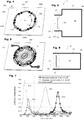
- the wafer used is formed by the silicon membrane of an electro-dynamic micro speaker made in MEMS technology (for Micro Electro Mechanical Systems), as described in the thesis of Iman Shahosseini, "Towards micro-speakers with high electroacoustic performance in silicon technology", PhD thesis, Institute of Fundamental Electronics, 2012 , or in I. Shahosseini et al., "Towards high fidelity high efficiency mems microspeakers", IEEE International conference on sensors, pp. 2426-2430, 2010 ..
- These electrodynamic silicon micro-HP have the distinction of having a thickness less than a centimeter while having a resonance frequency comparable to that of a conventional mid-range speaker (500Hz), which allows good integration into a thin environment, for example in a wall less than 50mm.
- the patch 32 is formed by an inner part cut from a rigid plate 320.
- This cutting is carried out according to a pattern comprising several cuts 330 which surround the pad 32 over almost all of it.
- several essentially linear cuts (that is to say monodimensional) 330 are made at angular positions distributed regularly around the center C32 of the patch, here in six identical cuts.
- Each of these cutouts 330 covers an angular portion of the periphery, deviating from the center 32 by a determined distance, which will correspond to the width of the arms and to the distance E31 between the periphery of the mobile patch 325 and the wall of the neck. 31.
- Each of these cutouts extends partially along its neighbors, inward in one direction (here counterclockwise) and outward in the other direction (here clockwise).
- the remaining material forms an arm developing in a spiral and extending along the periphery of the patch, over a length L330 much greater than the distance E31 between neck and patch . It is thus possible to obtain arms 331 (in gray in the figure), of a significant length and therefore of a low stiffness, despite the rigidity of the material of the initial plate 320.
- the initial plate 320 is made of silicon with a total thickness of 20 ⁇ m and external dimensions of 23 mm ⁇ 28 mm, for example monocrystalline silicon, for example obtained from a SOI type substrate.
- the patch 32 cut from this plate has a diameter of 13mm, and the cuts 330 have a width of the order of 20 ⁇ m.
- the cutouts 330 widen in a circular shape (in black in FIGURE 4 and FIGURE 5 ) to limit the fatigue of the material and avoid crack initiation.
- this patch also carries stiffeners 34, produced by methods known in the MEMS field, formed by ribs protruding from its surface over a certain height, here 300 ⁇ m.
- the total thickness of the pellet, from the point of view of its rigidity, is thus 320 ⁇ m.
- the loudspeaker thus produced further comprises a series of electrical tracks deposited on the periphery of the patch to form an electromagnetic coil (optional) 324, and which are connected to the fixed part by two of the arms of suspension 331, 20 ⁇ m thick, also formed by cutting the initial plate 320.
- the electromagnetic system of this loudspeaker is completed by a permanent annular magnet 374, fixed inside the neck 31 to interact with the coil 324.
- This magnet is for example composed of 2 neodymium-iron-boron annular magnets whose value theoretical polarization is 1.5T, as described in the Shahosseini thesis.
- the FIGURE 6 is a block diagram which illustrates this absorber 3, with a suspension 33 which is not leaktight and of a very low stiffness (in dotted rounded lines) which can be considered as negligible compared to the stiffness of the patch 32 (and therefore favoring the piston mode), despite the fact that the suspension and the pellet are formed by the same initial plate.
- the pellet vibrates in piston mode while moving between extreme positions 32a and 32b (dotted lines in FIGURE 6 ).
- the amplitude of these displacements corresponds to a maximum displacement of less than 2mm from the equilibrium position (in solid lines), and the suspension allows displacement without rupture of up to approximately 4mm.
- the FIGURE 7 thus shows the absorption results in purely passive mode, in a test carried out within a Kundt tube, with the cavity alone (curves in solid lines) and with the loudspeaker unpowered and without its seal (curves in lines dotted line).
- the curve R1a shows the absorption coefficient obtained with the cavity alone, with a maximum of the order of 0.42 for the measured frequency of 420Hz.
- the curve R3a shows that the absorption coefficient presents a greatly increased maximum which goes up to 0.86, for a frequency shifted down to 316Hz.
- the curve R1b shows the absorption coefficient obtained with the cavity alone, with a maximum of the order of 0, 58 for the frequency of 1310Hz.
- the curve R3b shows that the absorption coefficient has an increased maximum which goes up to 0.72, for a frequency this time greatly shifted downwards to around 930Hz.
- FIGURE 8 is illustrated a block diagram of an absorber according to a second exemplary embodiment of the invention, described only in its differences, which has the particularity of having a neck forming the continuity of the cavity.
- Such a configuration which can be combined with the other embodiments presented here, makes it possible to vary the possibilities of configuration and agreement, and to improve the compactness and / or the ease of manufacture of the device.
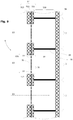
- the FIGURE 9 illustrates an acoustic wall 5 according to a third exemplary embodiment of the invention, comprising a plurality of absorbers 3, for example that of the FIGURE 4 .
- This wall is formed by a plate 500 having a periodic honeycomb structure, the housings of which are parallel to the direction of entry D3 of its absorbers 3.
- This plate 500 is sealed on its rear face by a waterproof layer 58, for example a layer of composite or a glued sheet or sheet.
- This periodic honeycomb architecture makes it possible, for example, to produce an acoustic wall comprising a very high surface density of absorbers while limiting the thickness of the assembly, even if it means using a honeycomb with large housings. transversely to the direction of entry to obtain a substantial cavity volume while keeping a small overall thickness, for example of less than 100 mm or even less than 50 mm.
- this honeycomb plate 500 On its front face, this honeycomb plate 500 is covered with two layers 511 and 513, which are perforated to form a neck 31 of length L31 and of area A31 for each of the housings 30 of the honeycomb. These two perforated layers 511, 513 enclose between them a plate or sheet 812 which is cut to form the pellets 32 of each absorber 3 and their suspensions 33, for example according to patterns 330 as described in FIGURE 4 or the like.
- Such an architecture can be produced, for example, with a sheet 512 of steel, or of aluminum, or of titanium alloy, which allows industrial production to be much more economical and rapid than with MEMS technologies of the FIGURE 3 , and more suited to large industrial applications and / or large series, for example for aircraft reactors or machine soundproofing.
- FIGURE 10a and b illustrate an absorber 6, according to a fourth exemplary embodiment of the invention, as a variant within an acoustic wall 500 of honeycomb similar to that of the FIGURE 9 , and which will only be described in its differences.
- the neck 61 is formed essentially by the thickness of a perforated layer 612, applied to the front face of the honeycomb.
- projections 6140 extend towards the inside of the neck 61 and protrude above the patch 62. These projections are distributed, sufficiently numerous and / or over sufficiently angular sectors extended, to maintain the patch 62 inside the neck 61 whatever the stresses it undergoes and the position in which to absorb it is in relation to the force of gravity.
- the patch is thus completely free to move in the direction of entry A3, and can be considered as being suspended by a link of zero stiffness, which makes it possible to obtain performances which can be advantageous in many cases.
- these retaining projections 6140 and 6110 are formed by an outer layer 614 pressed on the outside face of the thick layer 613, and by an inside layer 611 pressed on its inside face.
- Each of these retaining layers 611, 640 is for example put in place and then cut to form these projections, or for example formed by deposition in a pattern respecting the outline of the neck and the projections.
- the patch is for example made from a sheet 612 sandwiched between two layers of the front face, and which is cut to form each patch.
- This base sheet 612 is here shown between the inner retaining layer 611 and the thick layer 612, but could also be placed on the outside or between two thick layers.
- FIGURE 11a and FIGURE 11b illustrate an absorber 7, of a honeycomb acoustic wall, according to two variants of a fifth exemplary embodiment of the invention, variant within an acoustic wall 500 of honeycomb similar to that of the FIGURE 10 , and which will only be described in its differences.
- the patch 72, 72 ′ is also freely movable and retained by external layers 711 and 713, which protrude from the thick layer 712 above the neck 71.
- This patch has here a significant thickness depending on the direction of entry D3, sufficient to avoid bracing, and a periphery which follows the walls of the neck 71 so as to allow it to be guided there during its movements, while leaving a leakage section to produce the damper according to the invention.
- the leakage section is made by the outer periphery of the patch, as indicated by the arrows f72.
- the pad 72 ' is surrounded by a sliding surface 721, forming a linear bearing which guides its movement.
- This surface is for example produced according to a "free” or “sliding" fit, that is to say just free enough to allow mobility.
- Such an adjustment is for example of type H7g6 to H11d11 according to the ISO system for metal or plastic parts, or with a clearance of less than 0.5mm or even less than 0.2mm or 0.1mm for less precise manufacturing or composite materials.
- Such adjusted guidance can be assimilated to a seal, and can therefore be qualified as a "sliding joint".
- This sliding joint is produced for example by a conventional covering such as bronze, or silicone or PTFE; dry or with a liquid film of lubricant, or with a ferrofluid film.
- a conventional covering such as bronze, or silicone or PTFE
- the patch itself has one or more through orifices 731 made in the material of the patch which then form a leakage section f72 '.
- the tablet has a closed volume over its entire thickness.
- its two extreme surfaces follow the wall of the neck, but are connected to each other by a part of smaller section.
- Such variants allow more flexibility in the design by varying the various parameters, for example the friction surface against the neck, the mass of the patch, and / or its overall rigidity.
- the FIGURE 13 illustrates a seventh exemplary embodiment, which will be described only in its differences.
- the rigid patch also has one or more through openings 330a in its interior or even central part.
- these interior openings 330a thus form a leakage section which is added to that 330 produced around the arms 31 of the non-sealed suspension, which is for example similar to that of the FIGURE 4 .
- the suspension is of a sealed type, for example formed by an annular bellows made of a metal foil or a plastic or polymer film, for example a speaker of Visaton K16 type, the membrane of which forms the pellet , with its seal 33a in thermoformed polymer forming suspension.
- the internal openings 330a then form the only leakage section.
- FIGURE 14 illustrates an eighth exemplary embodiment, which will be described only in its differences.
- the patch 92 also includes, or even exclusively, leak openings 930a located inside the patch (that is to say of the rigid part).
- the patch 9b is formed by a layer 921 of a flexible and elastic material, for example a metal sheet or an elastomer, here of constant thickness.
- This elastomer is for example a PDMS, or polydimethylsiloxane, a polymeric material formed from a crosslinker and a prepolymer, in particular with a crosslinker: prepolymer ratio of 1:10 for which it is particularly flexible.
- the patch is fixed to the front wall 37 by an annular part 931a formed in a bellows having perforated parts 930a, which provides an unsealed suspension.
- the patch 92a has a thickening providing increased rigidity in an annular region 922a surrounding the interior openings 930a.
- This extra thickness 922a is here made of a different and preferably rigid material, for example an overmolding or a polymerized resin. This extra thickness, for example in its material and / or its dimensions, provides localized rigidity and additional mass which play on the characteristics of the moving assembly in order to obtain a displacement in piston mode at the desired absorption frequency.
- the patch 92b is formed by a layer 921b whose thickness is increasing inwards, at least even exclusively in the annular excess thickness 922b.
- the suspension 931b is presented in a waterproof version.
- the inner part has a certain elasticity but is less stressed by the friction of the air since it carries the openings making the leakage section.
- the displacement in "piston" mode is obtained by a stiffness and / or a greater mass in the part which surrounds the suspension, compared to the stiffness of the suspension itself, and / or by the fact that the central openings 930a in the central part let the air pass and undergo a less effort on the part of the acoustic wave.
- FIGURE 15 The operation in "piston” mode as understood herein is illustrated, compared with operation with a "drum” mode.
- a membrane or a plate 12 is fixed inside an orifice in a rigid wall 17. This plate 12 vibrates in "drum” mode when its center moves according to the arrow mT much more than its periphery 123, deforming thus from a distance d t .
- a plate or a pad 32 is fixed inside a hole in a rigid wall 37 by a suspension 33.
- This pad 32 vibrates in "piston" mode when its center moves according to the arrow mP almost as much as more than its periphery 323, for example because the suspension has a very low stiffness compared to that of the pellet.
- mP the center moves according to the arrow mP
- the suspension has a very low stiffness compared to that of the pellet.
- the FIGURE 12 illustrates an absorber a sixth exemplary embodiment of the invention.
- This absorber 8 uses a conventional structure of electrodynamic loudspeaker, here of a conical membrane type 82 and moving coil 824 mounted on a conventional perforated frame 85 carrying a permanent magnet 874.
- This structure is mounted on a front face 87, and enclosed in a cavity 80 delimited by walls 88 and 89.
- the membrane 82 is connected to the front face 87 by a flexible peripheral seal 83 of a conventional type.
- this joint 83 is here perforated by cutouts 830 (represented by a dotted rectangle), made during manufacture or subsequently.
- the seal and / or the membrane 82 and / or "spider" 84 which connects the top of the cone 82 to the frame 85 can also be perforated by cutouts 840.
- the membrane itself comprises perforated parts forming all or part of the leakage sections.
- Such an absorber is here represented in a version including the electromagnetic system 824, 874 of activation.
- This version can be used passively, by not connecting the coil or by disconnecting it from the control. It can also be used in a hybrid way by activating the loudspeaker to achieve active absorption in addition to the modified Helmholtz resonance. It can also be performed in a multi-role manner, for example to achieve absorption (active or passive) at certain times and serve as classical sound system at other times.
- the absorber can also be produced with an incomplete loudspeaker structure, that is to say for example with the same mechanical structure but without the electromagnetic system.
- Such an architecture can be particularly advantageous for large rooms, and / or large walls, in which the integration and the thickness are less important constraints. It can allow one or more absorbers to be placed in specific locations on the wall or in the room, possibly in versions of different sizes and frequencies, and in variable numbers on demand according to needs.
- this absorber can also be used in active operation, with acoustic impedance adaptation and / or in active reduction.
- FIGURE 16 the MEMs type speaker shown in FIGURE 5 , installed with its electrodynamic motor 374, 324 in the neck 31 of the absorber of the FIGURE 3 , for example for use in active operation, with acoustic impedance adaptation and / or active reduction.
Landscapes
- Physics & Mathematics (AREA)
- Acoustics & Sound (AREA)
- Engineering & Computer Science (AREA)
- Architecture (AREA)
- Structural Engineering (AREA)
- Civil Engineering (AREA)
- Electromagnetism (AREA)
- Multimedia (AREA)
- Signal Processing (AREA)
- Health & Medical Sciences (AREA)
- Otolaryngology (AREA)
- Soundproofing, Sound Blocking, And Sound Damping (AREA)
- Building Environments (AREA)
- Audible-Bandwidth Dynamoelectric Transducers Other Than Pickups (AREA)
- Diaphragms For Electromechanical Transducers (AREA)
Claims (16)
- Akustische Absorbervorrichtung (3, 4, 6, 7, 8), insbesondere passiv, umfassend ein Gehäuse (37, 38, 39, 39, 39, 87, 88, 89), das einen Hohlraum (30, 80) begrenzt, der sich in einer Eintrittsrichtung (D3) nach außen öffnet, durch mindestens eine Öffnung, die durch eine Vorderwand (37) einer bestimmten Dicke verläuft, wodurch ein Hals (31, 41, 61, 71, 81) mit einer bestimmten Öffnungsfläche (A31) und einer bestimmten Länge (L31) gebildet wird, wobei die Abmessungen des Gehäuses und des Halses bestimmt sind, um gemeinsam einen Helmholtz-Resonator für eine erste Frequenz oder einen ersten Frequenzbereich zu bilden, die sogenannte Eigenfrequenz,
dadurch gekennzeichnet, dass wenigstens ein bewegliches Element, oder ein Wafer (32, 42, 62, 72a, 72b, 92a, 92b), umfasst ist, das an dem Gehäuse durch eine oder mehrere mechanische Verbindungen oder Aufhängungen (33, 43, 6140, 83, 931a, 931b) in einer Position, die den mindestens einen Hals teilweise blockiert, aufgehängt ist, d.h. nicht über den gesamten oder einen Teil seines Weges abdichtet; und dass die Aufhängungssteifigkeit und die Steifigkeit des Wafers in ihrer Kombination, insbesondere in ihrem Verhältnis, bestimmt werden, so dass der Wafer in einem kolbenartigen Resonanzmodus entsprechend der Richtung der einfallenden Welle (D3) bei einer zweiten Frequenz oder einem zweiten Frequenzbereich, der sich von der ersten Frequenz unterscheidet, und insbesondere niedriger, ist, schwingt, wodurch eine Absorption für diese zweite Frequenz oder den zweiten Frequenzbereich erreicht wird. - Vorrichtung nach einem der vorhergehenden Ansprüche, dadurch gekennzeichnet, dass der Wafer (32, 42, 62, 72a, 72b, 92a, 92b) aus einem oder mehreren Materialien hergestellt ist, ausgewählt aus Silizium, Quarz, Aluminiumoxid, Titan und seinen Legierungen, Stahl, Aluminium und seinen Legierungen, Kunststoffen und insbesondere Polymeren.
- Vorrichtung nach einem der vorhergehenden Ansprüche, dadurch gekennzeichnet, dass die Aufhängungen (33, 43, 6140, 83, 931a, 931b) aus einem Material und unter Verwendung einer Geometrie hergestellt sind, um ein elastisches Verhalten mit einer Steifigkeit für die Bewegung des Wafers in seinem Umfang von weniger als 6N/m und insbesondere von weniger als 2N/m für einen Wafer mit einem durchschnittlichen Durchmesser zwischen 10mm und 20mm zur Verfügung zu stellen.
- Vorrichtung (3) nach einem der vorhergehenden Ansprüche, dadurch gekennzeichnet, dass die Aufhängungen (33) längliche Arme (331) umfassen, die den Wafer (32) mit dem Gehäuse (37) in einer Form verbinden, die sich parallel zum Rand des Halses (31) und/oder des Wafers (32) um den Wafer erstreckt.
- Vorrichtung (3) nach Anspruch 4, dadurch gekennzeichnet, dass der Wafer (32) innerhalb eines Blech (320, 512, 612) oder eines mit dem Gehäuse (37) integralen Blechs durch einen Teil hergestellt ist, der in Bezug auf das Gehäuse mittels eines oder mehrerer Ausschnitte (330), die in dem Blech oder der Folie hergestellt sind, beweglich gemacht wird, um Aufhängearme (331) zu bilden.
- Vorrichtung (6, 7) nach einem der Ansprüche 1 bis 3, dadurch gekennzeichnet, dass der Wafer (62, 72a, 72b) im Hals durch einen oder mehrere Vorschübe gehalten wird, die an beiden Enden aus dem Hals herausragen, um sich vor dem Umfang des Wafers zu erstrecken, um so einen Anschlag zu bilden, der verhindert, dass der Wafer aus dem Hals entweicht.
- Vorrichtung (7) nach einem der vorhergehenden Ansprüche, dadurch gekennzeichnet, dass der Wafer (72a, 72b) einen Umfang aufweist, der der Innenfläche des Halses mit einer bestimmten Abweichung über eine ausreichend bestimmte Länge entspricht, in Kombination mit der Abweichung und der Art der Materialien des Halses und des Wafers, um es dem Wafer zu ermöglichen, sich entlang des Halses zu bewegen (D3), ohne seine Blockierung durch Kippen und Wölben zu verursachen.
- Vorrichtung (8) nach einem der Ansprüche 1 bis 3, dadurch gekennzeichnet, dass der Wafer durch eine Membran (82) eines Lautsprechers gebildet ist, die an einem äußeren Rahmen (87, 85) durch eine flexible Umfangsdichtung (83, 84) befestigt ist, und dass die Dichtung einen oder mehrere Aussparungen (830, 840) aufweist, die die Membran über mindestens 20% seines Umfangs und insbesondere mindestens 40% umgeben.
- Vorrichtung nach einem der vorhergehenden Ansprüche, dadurch gekennzeichnet, dass der Wafer (32, 82) ferner mit dem Gehäuse durch ein elektromagnetisches System (324, 374, 824, 874) zusammenwirkt, um die Membran eines Lautsprechers zu bilden, und dass das elektromagnetische System durch eine elektronische Schaltung gesteuert wird:- um eine aktive Schallabsorption zu erreichen, und/oder- um die akustische Impedanz des Lautsprechers zu modifizieren, um die Absorption zu verbessern, die Absorptionsfrequenz zu verschieben, den Absorptionsfrequenzbereich zu erweitern oder eine Kombination dieser Effekte.
- Schallabsorbierende Wand (5), umfassend eine Vielzahl von Vorrichtungen (3, 4, 6, 7, 8) nach einem der vorhergehenden Ansprüche, die innerhalb einer kontinuierlichen zweidimensionalen Anordnung nebeneinander angeordnet sind, um eine Schallabsorption in einer gemeinsamen Richtung (D3) bereitzustellen.
- Wand nach dem vorstehenden Anspruch, dadurch gekennzeichnet, dass sie eine Platte (500) mit einer Wabenstruktur umfasst, deren Höhlungen eine Vielzahl von Hohlräumen (30) bilden, die auf einer sogenannten Rückseite geschlossen (58) sind,
und deren Hohlräume auf einer Vorderseite durch eine oder mehrere Wände (511, 512, 513, 611, 612, 613, 614) abgedeckt sind, die zu einer Vielzahl von Hälsen (31, 41, 71) geschnitten sind, die jeweils einen Wafer (32, 62, 72a, 72b) aufnehmen. - Verfahren zur Herstellung eines Schallabsorbers nach einem der Ansprüche 1 bis 9, der eine Zielfrequenz absorbieren soll, dadurch gekennzeichnet, dass es umfasst:- einen Schritt zum Bestimmen der Abmessungen eines Hohlraums (30, 80), der mit einem Hals (31, 41, 61, 71, 81) versehen ist, so dass der Hohlraum und der Hals einen Helmholtz-Hohlraum mit einer Helmholtz-Resonanz der ersten Frequenz bilden, die höher als die Zielfrequenz ist, und- einen Schritt zum Bestimmen der Eigenschaften eines hängenden Wafers, der geeignet ist, im Hals des Hohlraums angeordnet zu werden, um einen Absorber zu erzeugen, der auf eine zweite Frequenz abgestimmt ist, die der Zielfrequenz entspricht.
- Verfahren nach dem vorhergehenden Anspruch, wobei der hängende Wafer so bestimmt wird, dass die Aufhängung des Absorbers seinen ersten normalen Verformungsmodus bei einer Frequenz unterhalb der zweiten Frequenz aufweist.
- Verfahren nach dem vorstehenden Anspruch, dadurch gekennzeichnet, dass der Wafer des Schallabsorbers so bestimmt wird, dass er, wenn er frei ist, seinen ersten normalen Verformungsmodus bei einer Frequenz aufweist, die höher als die zweite Frequenz ist.
- Verfahren zur Herstellung eines Absorbers (3) nach einem der Ansprüche 1 bis 6 oder einer Wand (5) nach einem der Ansprüche 10 bis 11, dadurch gekennzeichnet, dass es mindestens einen Schritt zum Ausschneiden (330) eines Blechs oder einer Platte oder einer Folie (320, 512, 612) umfasst, um eine oder mehrere Wafern (32, 62) des Schallabsorbers zu bilden.
- Verfahren nach dem vorstehenden Anspruch, dadurch gekennzeichnet, dass das Blech oder die Platte oder die Folie (320, 512, 612) an der Oberfläche einer Platte (500) mit einer Wabenstruktur befestigt wird, und dass der Ausschnitt (330) eine Vielzahl von Wafern erzeugt, die in Bezug auf die Höhlungen der Wabenstruktur verteilt sind, um die Vielzahl von Wafern (32, 62) einer akustischen Wand (5) nach Anspruch 11 zu bilden.
Applications Claiming Priority (2)
| Application Number | Priority Date | Filing Date | Title |
|---|---|---|---|
| FR1650983A FR3047600B1 (fr) | 2016-02-08 | 2016-02-08 | Absorbeur acoustique, paroi acoustique et procede de conception et fabrication |
| PCT/EP2017/052787 WO2017137455A1 (fr) | 2016-02-08 | 2017-02-08 | Absorbeur acoustique, paroi acoustique et procede de conception et fabrication |
Publications (2)
| Publication Number | Publication Date |
|---|---|
| EP3414756A1 EP3414756A1 (de) | 2018-12-19 |
| EP3414756B1 true EP3414756B1 (de) | 2020-01-29 |
Family
ID=56555445
Family Applications (1)
| Application Number | Title | Priority Date | Filing Date |
|---|---|---|---|
| EP17706702.2A Active EP3414756B1 (de) | 2016-02-08 | 2017-02-08 | Akustischer absorber, akustische wand und verfahren zur konstruktion und herstellung |
Country Status (7)
| Country | Link |
|---|---|
| US (1) | US10477302B2 (de) |
| EP (1) | EP3414756B1 (de) |
| JP (1) | JP6985575B2 (de) |
| KR (1) | KR20180111976A (de) |
| CN (1) | CN108780637B (de) |
| FR (1) | FR3047600B1 (de) |
| WO (1) | WO2017137455A1 (de) |
Families Citing this family (15)
| Publication number | Priority date | Publication date | Assignee | Title |
|---|---|---|---|---|
| US11514878B2 (en) * | 2018-02-23 | 2022-11-29 | Purdue Research Foundation | Helmholtz resonators with broadband capability |
| US11322126B2 (en) * | 2018-12-20 | 2022-05-03 | Toyota Motor Engineering & Manufacturing North America, Inc. | Broadband sparse acoustic absorber |
| CN112969830B (zh) * | 2018-12-21 | 2022-12-27 | 香港科技大学 | 软声学边界平板 |
| CN110012397B (zh) * | 2019-05-10 | 2020-12-29 | 美特科技(苏州)有限公司 | 一种扬声器 |
| CN110415675A (zh) * | 2019-08-22 | 2019-11-05 | 北京市劳动保护科学研究所 | 可调声学特性的隔声装置 |
| WO2021038552A1 (en) * | 2019-08-28 | 2021-03-04 | Sonicedge Ltd. | A system and method for generating an audio signal |
| CN112447162A (zh) * | 2019-08-29 | 2021-03-05 | 比亚迪股份有限公司 | 吸声结构设计方法、吸声结构及声学包结构 |
| CN111926933B (zh) * | 2019-12-24 | 2021-06-15 | 南京林业大学 | 一种基于亥姆霍兹共鸣器的可调频吸声板 |
| CN112509545B (zh) * | 2020-12-16 | 2022-07-12 | 上海交通大学 | 基于共振吸声的多层嵌套式低频宽带吸声装置 |
| CN113112975A (zh) * | 2021-04-20 | 2021-07-13 | 南京富罗新环保科技有限公司 | 一种具有电磁吸声结构的吸声板 |
| CN117242514A (zh) * | 2021-04-23 | 2023-12-15 | 香港科技大学 | 超低频吸声器 |
| CN113539223B (zh) * | 2021-07-11 | 2022-05-06 | 哈尔滨工程大学 | 一种亥姆霍兹吸声装置 |
| WO2023173442A1 (zh) * | 2022-03-18 | 2023-09-21 | 深圳市韶音科技有限公司 | 一种振动组件 |
| KR20240013315A (ko) * | 2022-07-22 | 2024-01-30 | (주)새론건설 | 소음 방지 공명기 및 이의 설치 방법 |
| US11991497B1 (en) * | 2022-10-28 | 2024-05-21 | xMEMS Labs, Inc. | Acoustic device and holder flattening frequency response |
Family Cites Families (15)
| Publication number | Priority date | Publication date | Assignee | Title |
|---|---|---|---|---|
| JPS5763400U (de) * | 1980-10-01 | 1982-04-15 | ||
| JPS6440895A (en) * | 1987-08-06 | 1989-02-13 | Matsushita Electric Works Ltd | Sound absorber |
| US5241512A (en) * | 1991-04-25 | 1993-08-31 | Hutchinson 2 | Acoustic protection material and apparatus including such material |
| WO2004066668A2 (en) * | 2003-01-16 | 2004-08-05 | Performance Media Industries, Ltd. | Room mode bass absorption through combined diaphragmatic & helmholtz resonance techniques |
| DE102004053383A1 (de) * | 2004-11-02 | 2006-05-04 | Eads Deutschland Gmbh | Akustischer Absorber für Flugtriebwerke |
| CH700728B1 (de) * | 2007-07-13 | 2010-10-15 | Albers & Co | Akustikelemente. |
| DE102007000568A1 (de) * | 2007-10-24 | 2009-04-30 | Silencesolutions Gmbh | Schallabsorber |
| JP2009204836A (ja) * | 2008-02-27 | 2009-09-10 | Yamaha Corp | 吸音構造、吸音構造群、音響室、吸音構造の調整方法及び騒音低減方法 |
| DE102009007891A1 (de) * | 2009-02-07 | 2010-08-12 | Willsingh Wilson | Resonanz-Schallabsorber in mehrschichtiger Ausführung |
| FR2955443B1 (fr) * | 2010-01-19 | 2012-03-23 | Univ Maine | Structure de haut-parleur electrodynamique a technologie mems |
| US8469141B2 (en) * | 2011-08-10 | 2013-06-25 | General Electric Company | Acoustic damping device for use in gas turbine engine |
| JP5661581B2 (ja) * | 2011-09-07 | 2015-01-28 | 株式会社神戸製鋼所 | 遮音カバー |
| CH706394A2 (de) * | 2012-04-26 | 2013-10-31 | Akustik & Raum Ag | Schallabsorbierendes Element. |
| US8857563B1 (en) | 2013-07-29 | 2014-10-14 | The Boeing Company | Hybrid acoustic barrier and absorber |
| FR3009122B1 (fr) * | 2013-07-29 | 2017-12-15 | Boeing Co | Barriere et absorbeur acoustiques hybrides |
-
2016
- 2016-02-08 FR FR1650983A patent/FR3047600B1/fr not_active Expired - Fee Related
-
2017
- 2017-02-08 CN CN201780010387.0A patent/CN108780637B/zh active Active
- 2017-02-08 US US16/075,926 patent/US10477302B2/en active Active
- 2017-02-08 WO PCT/EP2017/052787 patent/WO2017137455A1/fr active Application Filing
- 2017-02-08 JP JP2018560253A patent/JP6985575B2/ja active Active
- 2017-02-08 KR KR1020187026092A patent/KR20180111976A/ko not_active Application Discontinuation
- 2017-02-08 EP EP17706702.2A patent/EP3414756B1/de active Active
Non-Patent Citations (1)
| Title |
|---|
| None * |
Also Published As
| Publication number | Publication date |
|---|---|
| FR3047600A1 (fr) | 2017-08-11 |
| FR3047600B1 (fr) | 2018-02-02 |
| EP3414756A1 (de) | 2018-12-19 |
| CN108780637A (zh) | 2018-11-09 |
| JP6985575B2 (ja) | 2021-12-22 |
| WO2017137455A1 (fr) | 2017-08-17 |
| CN108780637B (zh) | 2023-07-25 |
| KR20180111976A (ko) | 2018-10-11 |
| US20190058941A1 (en) | 2019-02-21 |
| JP2019511014A (ja) | 2019-04-18 |
| US10477302B2 (en) | 2019-11-12 |
Similar Documents
| Publication | Publication Date | Title |
|---|---|---|
| EP3414756B1 (de) | Akustischer absorber, akustische wand und verfahren zur konstruktion und herstellung | |
| EP1943876B1 (de) | Elektrodynamischer wandler mit einer kuppel mit einer eisenfluid-suspension | |
| FR2473242A1 (fr) | Transducteur electroacoustique a dome actif | |
| EP3538479B1 (de) | Vorrichtung zur übertragung einer bewegung und einer kraft zwischen zwei voneinander isolierten zonen | |
| FR2987616A1 (fr) | Dispositif transducteur micromecanique de son et son procede de realisation | |
| FR3063854A1 (fr) | Resonateur saw a couches d'attenuation d'ondes parasites | |
| EP0852050B1 (de) | Verfahren zur dämpfung von schwingungen und der von einem material abgestrahlten druckwelle | |
| EP3213531B1 (de) | Elektroakustischer wandler, entsprechende anordnung und vorrichtung | |
| FR3013935B1 (fr) | Film transducteur electro-actif de son ayant une surface structuree | |
| EP3009894B1 (de) | Anordnung mit Schallabstrahlungsmembranen für eine Armbanduhr mit Schlagwerk | |
| FR2955731A1 (fr) | Enceinte acoustique comprenant au moins une membrane d'attenuation acoustique | |
| EP4075422A1 (de) | Mikrometrischer lautsprecher | |
| EP2881807B1 (de) | Schallabstrahlungsmembran für eine Armbanduhr mit Spieluhr | |
| EP2881806B1 (de) | Schallabstrahlungsmembran für eine Armbanduhr mit Spieluhr | |
| EP3892011A1 (de) | Unendliches leitblech mit geringer steifigkeit | |
| CA2757170A1 (fr) | Panneau acoustique destine a recevoir, emettre ou absorber des sons | |
| FR3045264A1 (fr) | Membrane acoustique pour haut-parleur et haut-parleur correspondant | |
| EP3278330B1 (de) | Vorrichtung zur akustischen impedanzanpassung und lautsprecher mit solch einer vorrichtung | |
| EP3167170A2 (de) | Schalldämpfungsvorrichtung und -verfahren | |
| EP2392151B1 (de) | Bewegliches teil und mit einem solchen beweglichen teil ausgestatteter elektrodynamischer wandler | |
| CH708957A2 (fr) | Membrane de rayonnement acoustique pour une montre musicale. | |
| EP0785825A1 (de) | Akustischer unterwassersender für grosse tauchtiefe | |
| EP3015177A1 (de) | Ultraschall-signalwandler mit einer schicht aus mikroballons |
Legal Events
| Date | Code | Title | Description |
|---|---|---|---|
| STAA | Information on the status of an ep patent application or granted ep patent |
Free format text: STATUS: UNKNOWN |
|
| STAA | Information on the status of an ep patent application or granted ep patent |
Free format text: STATUS: THE INTERNATIONAL PUBLICATION HAS BEEN MADE |
|
| PUAI | Public reference made under article 153(3) epc to a published international application that has entered the european phase |
Free format text: ORIGINAL CODE: 0009012 |
|
| STAA | Information on the status of an ep patent application or granted ep patent |
Free format text: STATUS: REQUEST FOR EXAMINATION WAS MADE |
|
| 17P | Request for examination filed |
Effective date: 20180904 |
|
| AK | Designated contracting states |
Kind code of ref document: A1 Designated state(s): AL AT BE BG CH CY CZ DE DK EE ES FI FR GB GR HR HU IE IS IT LI LT LU LV MC MK MT NL NO PL PT RO RS SE SI SK SM TR |
|
| AX | Request for extension of the european patent |
Extension state: BA ME |
|
| RIN1 | Information on inventor provided before grant (corrected) |
Inventor name: LEFEUVRE, ELIE Inventor name: DURAND, STEPHANE Inventor name: YAAKOUBI, NOURDIN Inventor name: HOUDOUIN, ALEXANDRE Inventor name: MARTINCIC, EMILE Inventor name: AUREGAN, YVES |
|
| DAV | Request for validation of the european patent (deleted) | ||
| DAX | Request for extension of the european patent (deleted) | ||
| RIN1 | Information on inventor provided before grant (corrected) |
Inventor name: LEFEUVRE, ELIE Inventor name: DURAND, STEPHANE Inventor name: AUREGAN, YVES Inventor name: MARTINCIC, EMILE Inventor name: YAAKOUBI, NOURDIN Inventor name: HOUDOUIN, ALEXANDRE |
|
| REG | Reference to a national code |
Ref country code: DE Ref legal event code: R079 Ref document number: 602017011191 Country of ref document: DE Free format text: PREVIOUS MAIN CLASS: G10K0011160000 Ipc: E04B0001860000 |
|
| GRAP | Despatch of communication of intention to grant a patent |
Free format text: ORIGINAL CODE: EPIDOSNIGR1 |
|
| STAA | Information on the status of an ep patent application or granted ep patent |
Free format text: STATUS: GRANT OF PATENT IS INTENDED |
|
| RIC1 | Information provided on ipc code assigned before grant |
Ipc: E04B 1/84 20060101ALI20190717BHEP Ipc: G10K 11/16 20060101ALI20190717BHEP Ipc: E04B 1/86 20060101AFI20190717BHEP Ipc: H04R 9/06 20060101ALI20190717BHEP Ipc: H04R 1/28 20060101ALI20190717BHEP |
|
| INTG | Intention to grant announced |
Effective date: 20190802 |
|
| GRAS | Grant fee paid |
Free format text: ORIGINAL CODE: EPIDOSNIGR3 |
|
| GRAA | (expected) grant |
Free format text: ORIGINAL CODE: 0009210 |
|
| STAA | Information on the status of an ep patent application or granted ep patent |
Free format text: STATUS: THE PATENT HAS BEEN GRANTED |
|
| AK | Designated contracting states |
Kind code of ref document: B1 Designated state(s): AL AT BE BG CH CY CZ DE DK EE ES FI FR GB GR HR HU IE IS IT LI LT LU LV MC MK MT NL NO PL PT RO RS SE SI SK SM TR |
|
| REG | Reference to a national code |
Ref country code: GB Ref legal event code: FG4D Free format text: NOT ENGLISH |
|
| REG | Reference to a national code |
Ref country code: CH Ref legal event code: EP |
|
| REG | Reference to a national code |
Ref country code: AT Ref legal event code: REF Ref document number: 1228586 Country of ref document: AT Kind code of ref document: T Effective date: 20200215 |
|
| REG | Reference to a national code |
Ref country code: IE Ref legal event code: FG4D Free format text: LANGUAGE OF EP DOCUMENT: FRENCH |
|
| REG | Reference to a national code |
Ref country code: DE Ref legal event code: R096 Ref document number: 602017011191 Country of ref document: DE |
|
| REG | Reference to a national code |
Ref country code: NL Ref legal event code: MP Effective date: 20200129 |
|
| RAP2 | Party data changed (patent owner data changed or rights of a patent transferred) |
Owner name: UNIVERSITE DU MANS Owner name: UNIVERSITE PARIS-SACLAY Owner name: CENTRE NATIONAL DE LA RECHERCHE SCIENTIFIQUE |
|
| PG25 | Lapsed in a contracting state [announced via postgrant information from national office to epo] |
Ref country code: PT Free format text: LAPSE BECAUSE OF FAILURE TO SUBMIT A TRANSLATION OF THE DESCRIPTION OR TO PAY THE FEE WITHIN THE PRESCRIBED TIME-LIMIT Effective date: 20200621 Ref country code: NO Free format text: LAPSE BECAUSE OF FAILURE TO SUBMIT A TRANSLATION OF THE DESCRIPTION OR TO PAY THE FEE WITHIN THE PRESCRIBED TIME-LIMIT Effective date: 20200429 Ref country code: RS Free format text: LAPSE BECAUSE OF FAILURE TO SUBMIT A TRANSLATION OF THE DESCRIPTION OR TO PAY THE FEE WITHIN THE PRESCRIBED TIME-LIMIT Effective date: 20200129 Ref country code: FI Free format text: LAPSE BECAUSE OF FAILURE TO SUBMIT A TRANSLATION OF THE DESCRIPTION OR TO PAY THE FEE WITHIN THE PRESCRIBED TIME-LIMIT Effective date: 20200129 |
|
| REG | Reference to a national code |
Ref country code: LT Ref legal event code: MG4D |
|
| PG25 | Lapsed in a contracting state [announced via postgrant information from national office to epo] |
Ref country code: GR Free format text: LAPSE BECAUSE OF FAILURE TO SUBMIT A TRANSLATION OF THE DESCRIPTION OR TO PAY THE FEE WITHIN THE PRESCRIBED TIME-LIMIT Effective date: 20200430 Ref country code: HR Free format text: LAPSE BECAUSE OF FAILURE TO SUBMIT A TRANSLATION OF THE DESCRIPTION OR TO PAY THE FEE WITHIN THE PRESCRIBED TIME-LIMIT Effective date: 20200129 Ref country code: SE Free format text: LAPSE BECAUSE OF FAILURE TO SUBMIT A TRANSLATION OF THE DESCRIPTION OR TO PAY THE FEE WITHIN THE PRESCRIBED TIME-LIMIT Effective date: 20200129 Ref country code: IS Free format text: LAPSE BECAUSE OF FAILURE TO SUBMIT A TRANSLATION OF THE DESCRIPTION OR TO PAY THE FEE WITHIN THE PRESCRIBED TIME-LIMIT Effective date: 20200529 Ref country code: BG Free format text: LAPSE BECAUSE OF FAILURE TO SUBMIT A TRANSLATION OF THE DESCRIPTION OR TO PAY THE FEE WITHIN THE PRESCRIBED TIME-LIMIT Effective date: 20200429 Ref country code: LV Free format text: LAPSE BECAUSE OF FAILURE TO SUBMIT A TRANSLATION OF THE DESCRIPTION OR TO PAY THE FEE WITHIN THE PRESCRIBED TIME-LIMIT Effective date: 20200129 |
|
| PG25 | Lapsed in a contracting state [announced via postgrant information from national office to epo] |
Ref country code: NL Free format text: LAPSE BECAUSE OF FAILURE TO SUBMIT A TRANSLATION OF THE DESCRIPTION OR TO PAY THE FEE WITHIN THE PRESCRIBED TIME-LIMIT Effective date: 20200129 |
|
| REG | Reference to a national code |
Ref country code: BE Ref legal event code: MM Effective date: 20200229 |
|
| PG25 | Lapsed in a contracting state [announced via postgrant information from national office to epo] |
Ref country code: DK Free format text: LAPSE BECAUSE OF FAILURE TO SUBMIT A TRANSLATION OF THE DESCRIPTION OR TO PAY THE FEE WITHIN THE PRESCRIBED TIME-LIMIT Effective date: 20200129 Ref country code: LU Free format text: LAPSE BECAUSE OF NON-PAYMENT OF DUE FEES Effective date: 20200208 Ref country code: LT Free format text: LAPSE BECAUSE OF FAILURE TO SUBMIT A TRANSLATION OF THE DESCRIPTION OR TO PAY THE FEE WITHIN THE PRESCRIBED TIME-LIMIT Effective date: 20200129 Ref country code: SM Free format text: LAPSE BECAUSE OF FAILURE TO SUBMIT A TRANSLATION OF THE DESCRIPTION OR TO PAY THE FEE WITHIN THE PRESCRIBED TIME-LIMIT Effective date: 20200129 Ref country code: EE Free format text: LAPSE BECAUSE OF FAILURE TO SUBMIT A TRANSLATION OF THE DESCRIPTION OR TO PAY THE FEE WITHIN THE PRESCRIBED TIME-LIMIT Effective date: 20200129 Ref country code: CZ Free format text: LAPSE BECAUSE OF FAILURE TO SUBMIT A TRANSLATION OF THE DESCRIPTION OR TO PAY THE FEE WITHIN THE PRESCRIBED TIME-LIMIT Effective date: 20200129 Ref country code: RO Free format text: LAPSE BECAUSE OF FAILURE TO SUBMIT A TRANSLATION OF THE DESCRIPTION OR TO PAY THE FEE WITHIN THE PRESCRIBED TIME-LIMIT Effective date: 20200129 Ref country code: ES Free format text: LAPSE BECAUSE OF FAILURE TO SUBMIT A TRANSLATION OF THE DESCRIPTION OR TO PAY THE FEE WITHIN THE PRESCRIBED TIME-LIMIT Effective date: 20200129 Ref country code: MC Free format text: LAPSE BECAUSE OF FAILURE TO SUBMIT A TRANSLATION OF THE DESCRIPTION OR TO PAY THE FEE WITHIN THE PRESCRIBED TIME-LIMIT Effective date: 20200129 Ref country code: SK Free format text: LAPSE BECAUSE OF FAILURE TO SUBMIT A TRANSLATION OF THE DESCRIPTION OR TO PAY THE FEE WITHIN THE PRESCRIBED TIME-LIMIT Effective date: 20200129 |
|
| REG | Reference to a national code |
Ref country code: CH Ref legal event code: NV Representative=s name: DENNEMEYER AG, CH Ref country code: DE Ref legal event code: R097 Ref document number: 602017011191 Country of ref document: DE |
|
| REG | Reference to a national code |
Ref country code: AT Ref legal event code: MK05 Ref document number: 1228586 Country of ref document: AT Kind code of ref document: T Effective date: 20200129 |
|
| PLBE | No opposition filed within time limit |
Free format text: ORIGINAL CODE: 0009261 |
|
| STAA | Information on the status of an ep patent application or granted ep patent |
Free format text: STATUS: NO OPPOSITION FILED WITHIN TIME LIMIT |
|
| 26N | No opposition filed |
Effective date: 20201030 |
|
| PG25 | Lapsed in a contracting state [announced via postgrant information from national office to epo] |
Ref country code: IT Free format text: LAPSE BECAUSE OF FAILURE TO SUBMIT A TRANSLATION OF THE DESCRIPTION OR TO PAY THE FEE WITHIN THE PRESCRIBED TIME-LIMIT Effective date: 20200129 Ref country code: AT Free format text: LAPSE BECAUSE OF FAILURE TO SUBMIT A TRANSLATION OF THE DESCRIPTION OR TO PAY THE FEE WITHIN THE PRESCRIBED TIME-LIMIT Effective date: 20200129 |
|
| PG25 | Lapsed in a contracting state [announced via postgrant information from national office to epo] |
Ref country code: BE Free format text: LAPSE BECAUSE OF NON-PAYMENT OF DUE FEES Effective date: 20200229 Ref country code: PL Free format text: LAPSE BECAUSE OF FAILURE TO SUBMIT A TRANSLATION OF THE DESCRIPTION OR TO PAY THE FEE WITHIN THE PRESCRIBED TIME-LIMIT Effective date: 20200129 Ref country code: SI Free format text: LAPSE BECAUSE OF FAILURE TO SUBMIT A TRANSLATION OF THE DESCRIPTION OR TO PAY THE FEE WITHIN THE PRESCRIBED TIME-LIMIT Effective date: 20200129 |
|
| REG | Reference to a national code |
Ref country code: DE Ref legal event code: R081 Ref document number: 602017011191 Country of ref document: DE Owner name: UNIVERSITE PARIS-SACLAY, FR Free format text: FORMER OWNERS: CENTRE NATIONAL DE LA RECHERCHE SCIENTIFIQUE, 75016 PARIS, FR; UNIVERSITE DU MANS, LE MANS, FR; UNIVERSITE PARIS SUD, ORSAY, FR Ref country code: DE Ref legal event code: R081 Ref document number: 602017011191 Country of ref document: DE Owner name: UNIVERSITE DU MANS, FR Free format text: FORMER OWNERS: CENTRE NATIONAL DE LA RECHERCHE SCIENTIFIQUE, 75016 PARIS, FR; UNIVERSITE DU MANS, LE MANS, FR; UNIVERSITE PARIS SUD, ORSAY, FR Ref country code: DE Ref legal event code: R081 Ref document number: 602017011191 Country of ref document: DE Owner name: CENTRE NATIONAL DE LA RECHERCHE SCIENTIFIQUE, FR Free format text: FORMER OWNERS: CENTRE NATIONAL DE LA RECHERCHE SCIENTIFIQUE, 75016 PARIS, FR; UNIVERSITE DU MANS, LE MANS, FR; UNIVERSITE PARIS SUD, ORSAY, FR |
|
| REG | Reference to a national code |
Ref country code: GB Ref legal event code: 732E Free format text: REGISTERED BETWEEN 20211014 AND 20211020 |
|
| PG25 | Lapsed in a contracting state [announced via postgrant information from national office to epo] |
Ref country code: TR Free format text: LAPSE BECAUSE OF FAILURE TO SUBMIT A TRANSLATION OF THE DESCRIPTION OR TO PAY THE FEE WITHIN THE PRESCRIBED TIME-LIMIT Effective date: 20200129 Ref country code: MT Free format text: LAPSE BECAUSE OF FAILURE TO SUBMIT A TRANSLATION OF THE DESCRIPTION OR TO PAY THE FEE WITHIN THE PRESCRIBED TIME-LIMIT Effective date: 20200129 Ref country code: CY Free format text: LAPSE BECAUSE OF FAILURE TO SUBMIT A TRANSLATION OF THE DESCRIPTION OR TO PAY THE FEE WITHIN THE PRESCRIBED TIME-LIMIT Effective date: 20200129 |
|
| PG25 | Lapsed in a contracting state [announced via postgrant information from national office to epo] |
Ref country code: MK Free format text: LAPSE BECAUSE OF FAILURE TO SUBMIT A TRANSLATION OF THE DESCRIPTION OR TO PAY THE FEE WITHIN THE PRESCRIBED TIME-LIMIT Effective date: 20200129 Ref country code: AL Free format text: LAPSE BECAUSE OF FAILURE TO SUBMIT A TRANSLATION OF THE DESCRIPTION OR TO PAY THE FEE WITHIN THE PRESCRIBED TIME-LIMIT Effective date: 20200129 |
|
| PGFP | Annual fee paid to national office [announced via postgrant information from national office to epo] |
Ref country code: FR Payment date: 20230227 Year of fee payment: 7 |
|
| P01 | Opt-out of the competence of the unified patent court (upc) registered |
Effective date: 20230523 |
|
| PGFP | Annual fee paid to national office [announced via postgrant information from national office to epo] |
Ref country code: IE Payment date: 20240119 Year of fee payment: 8 |
|
| PGFP | Annual fee paid to national office [announced via postgrant information from national office to epo] |
Ref country code: DE Payment date: 20240213 Year of fee payment: 8 Ref country code: GB Payment date: 20240221 Year of fee payment: 8 Ref country code: CH Payment date: 20240301 Year of fee payment: 8 |