EP4075422A1 - Mikrometrischer lautsprecher - Google Patents
Mikrometrischer lautsprecher Download PDFInfo
- Publication number
- EP4075422A1 EP4075422A1 EP22168299.0A EP22168299A EP4075422A1 EP 4075422 A1 EP4075422 A1 EP 4075422A1 EP 22168299 A EP22168299 A EP 22168299A EP 4075422 A1 EP4075422 A1 EP 4075422A1
- Authority
- EP
- European Patent Office
- Prior art keywords
- loudspeaker
- micrometric
- frame
- mechanical
- acoustic transducer
- Prior art date
- Legal status (The legal status is an assumption and is not a legal conclusion. Google has not performed a legal analysis and makes no representation as to the accuracy of the status listed.)
- Granted
Links
Images


Classifications
-
- G—PHYSICS
- G10—MUSICAL INSTRUMENTS; ACOUSTICS
- G10K—SOUND-PRODUCING DEVICES; METHODS OR DEVICES FOR PROTECTING AGAINST, OR FOR DAMPING, NOISE OR OTHER ACOUSTIC WAVES IN GENERAL; ACOUSTICS NOT OTHERWISE PROVIDED FOR
- G10K9/00—Devices in which sound is produced by vibrating a diaphragm or analogous element, e.g. fog horns, vehicle hooters or buzzers
- G10K9/12—Devices in which sound is produced by vibrating a diaphragm or analogous element, e.g. fog horns, vehicle hooters or buzzers electrically operated
- G10K9/122—Devices in which sound is produced by vibrating a diaphragm or analogous element, e.g. fog horns, vehicle hooters or buzzers electrically operated using piezoelectric driving means
- G10K9/125—Devices in which sound is produced by vibrating a diaphragm or analogous element, e.g. fog horns, vehicle hooters or buzzers electrically operated using piezoelectric driving means with a plurality of active elements
-
- H—ELECTRICITY
- H04—ELECTRIC COMMUNICATION TECHNIQUE
- H04R—LOUDSPEAKERS, MICROPHONES, GRAMOPHONE PICK-UPS OR LIKE ACOUSTIC ELECTROMECHANICAL TRANSDUCERS; ELECTRIC HEARING AIDS; PUBLIC ADDRESS SYSTEMS
- H04R7/00—Diaphragms for electromechanical transducers; Cones
- H04R7/16—Mounting or tensioning of diaphragms or cones
- H04R7/24—Tensioning by means acting directly on free portions of diaphragm or cone
-
- B—PERFORMING OPERATIONS; TRANSPORTING
- B06—GENERATING OR TRANSMITTING MECHANICAL VIBRATIONS IN GENERAL
- B06B—METHODS OR APPARATUS FOR GENERATING OR TRANSMITTING MECHANICAL VIBRATIONS OF INFRASONIC, SONIC, OR ULTRASONIC FREQUENCY, e.g. FOR PERFORMING MECHANICAL WORK IN GENERAL
- B06B1/00—Methods or apparatus for generating mechanical vibrations of infrasonic, sonic, or ultrasonic frequency
- B06B1/02—Methods or apparatus for generating mechanical vibrations of infrasonic, sonic, or ultrasonic frequency making use of electrical energy
- B06B1/06—Methods or apparatus for generating mechanical vibrations of infrasonic, sonic, or ultrasonic frequency making use of electrical energy operating with piezoelectric effect or with electrostriction
- B06B1/0607—Methods or apparatus for generating mechanical vibrations of infrasonic, sonic, or ultrasonic frequency making use of electrical energy operating with piezoelectric effect or with electrostriction using multiple elements
- B06B1/0622—Methods or apparatus for generating mechanical vibrations of infrasonic, sonic, or ultrasonic frequency making use of electrical energy operating with piezoelectric effect or with electrostriction using multiple elements on one surface
- B06B1/0629—Square array
-
- H—ELECTRICITY
- H04—ELECTRIC COMMUNICATION TECHNIQUE
- H04R—LOUDSPEAKERS, MICROPHONES, GRAMOPHONE PICK-UPS OR LIKE ACOUSTIC ELECTROMECHANICAL TRANSDUCERS; ELECTRIC HEARING AIDS; PUBLIC ADDRESS SYSTEMS
- H04R1/00—Details of transducers, loudspeakers or microphones
- H04R1/20—Arrangements for obtaining desired frequency or directional characteristics
- H04R1/22—Arrangements for obtaining desired frequency or directional characteristics for obtaining desired frequency characteristic only
- H04R1/28—Transducer mountings or enclosures modified by provision of mechanical or acoustic impedances, e.g. resonator, damping means
- H04R1/2869—Reduction of undesired resonances, i.e. standing waves within enclosure, or of undesired vibrations, i.e. of the enclosure itself
- H04R1/2876—Reduction of undesired resonances, i.e. standing waves within enclosure, or of undesired vibrations, i.e. of the enclosure itself by means of damping material, e.g. as cladding
- H04R1/288—Reduction of undesired resonances, i.e. standing waves within enclosure, or of undesired vibrations, i.e. of the enclosure itself by means of damping material, e.g. as cladding for loudspeaker transducers
-
- H—ELECTRICITY
- H04—ELECTRIC COMMUNICATION TECHNIQUE
- H04R—LOUDSPEAKERS, MICROPHONES, GRAMOPHONE PICK-UPS OR LIKE ACOUSTIC ELECTROMECHANICAL TRANSDUCERS; ELECTRIC HEARING AIDS; PUBLIC ADDRESS SYSTEMS
- H04R17/00—Piezoelectric transducers; Electrostrictive transducers
-
- H—ELECTRICITY
- H04—ELECTRIC COMMUNICATION TECHNIQUE
- H04R—LOUDSPEAKERS, MICROPHONES, GRAMOPHONE PICK-UPS OR LIKE ACOUSTIC ELECTROMECHANICAL TRANSDUCERS; ELECTRIC HEARING AIDS; PUBLIC ADDRESS SYSTEMS
- H04R7/00—Diaphragms for electromechanical transducers; Cones
- H04R7/02—Diaphragms for electromechanical transducers; Cones characterised by the construction
-
- B—PERFORMING OPERATIONS; TRANSPORTING
- B06—GENERATING OR TRANSMITTING MECHANICAL VIBRATIONS IN GENERAL
- B06B—METHODS OR APPARATUS FOR GENERATING OR TRANSMITTING MECHANICAL VIBRATIONS OF INFRASONIC, SONIC, OR ULTRASONIC FREQUENCY, e.g. FOR PERFORMING MECHANICAL WORK IN GENERAL
- B06B2201/00—Indexing scheme associated with B06B1/0207 for details covered by B06B1/0207 but not provided for in any of its subgroups
- B06B2201/50—Application to a particular transducer type
- B06B2201/55—Piezoelectric transducer
-
- H—ELECTRICITY
- H04—ELECTRIC COMMUNICATION TECHNIQUE
- H04R—LOUDSPEAKERS, MICROPHONES, GRAMOPHONE PICK-UPS OR LIKE ACOUSTIC ELECTROMECHANICAL TRANSDUCERS; ELECTRIC HEARING AIDS; PUBLIC ADDRESS SYSTEMS
- H04R2201/00—Details of transducers, loudspeakers or microphones covered by H04R1/00 but not provided for in any of its subgroups
- H04R2201/003—Mems transducers or their use
-
- H—ELECTRICITY
- H04—ELECTRIC COMMUNICATION TECHNIQUE
- H04R—LOUDSPEAKERS, MICROPHONES, GRAMOPHONE PICK-UPS OR LIKE ACOUSTIC ELECTROMECHANICAL TRANSDUCERS; ELECTRIC HEARING AIDS; PUBLIC ADDRESS SYSTEMS
- H04R2207/00—Details of diaphragms or cones for electromechanical transducers or their suspension covered by H04R7/00 but not provided for in H04R7/00 or in H04R2307/00
- H04R2207/021—Diaphragm extensions, not necessarily integrally formed, e.g. skirts, rims, flanges
-
- H—ELECTRICITY
- H04—ELECTRIC COMMUNICATION TECHNIQUE
- H04R—LOUDSPEAKERS, MICROPHONES, GRAMOPHONE PICK-UPS OR LIKE ACOUSTIC ELECTROMECHANICAL TRANSDUCERS; ELECTRIC HEARING AIDS; PUBLIC ADDRESS SYSTEMS
- H04R2400/00—Loudspeakers
-
- H—ELECTRICITY
- H04—ELECTRIC COMMUNICATION TECHNIQUE
- H04R—LOUDSPEAKERS, MICROPHONES, GRAMOPHONE PICK-UPS OR LIKE ACOUSTIC ELECTROMECHANICAL TRANSDUCERS; ELECTRIC HEARING AIDS; PUBLIC ADDRESS SYSTEMS
- H04R2400/00—Loudspeakers
- H04R2400/11—Aspects regarding the frame of loudspeaker transducers
-
- H—ELECTRICITY
- H04—ELECTRIC COMMUNICATION TECHNIQUE
- H04R—LOUDSPEAKERS, MICROPHONES, GRAMOPHONE PICK-UPS OR LIKE ACOUSTIC ELECTROMECHANICAL TRANSDUCERS; ELECTRIC HEARING AIDS; PUBLIC ADDRESS SYSTEMS
- H04R2499/00—Aspects covered by H04R or H04S not otherwise provided for in their subgroups
- H04R2499/10—General applications
- H04R2499/11—Transducers incorporated or for use in hand-held devices, e.g. mobile phones, PDA's, camera's
Definitions
- the present invention relates to the field of micrometric loudspeakers. It finds for particularly advantageous application the integration of at least one loudspeaker in computers, mobile telephones and other headphones, in particular wireless.
- the loudspeaker is used to transform an electrical signal into sound pressure.
- loudspeakers have been miniaturized to be integrated in particular into computers, mobile telephones, connected speakers and other headphones, for example wireless.
- the loudspeaker is an electro-mechanical-acoustic transducer. In its linear principle, the operation of the loudspeaker involves the actuation of a membrane or a rigid plate, coupled to the ambient air.
- the electrical signal passes through an electromechanical transducer which converts the loudspeaker supply voltage into displacement.
- a mechanical-acoustic transducer very often a membrane, converts this displacement into acoustic pressure.
- a good loudspeaker is a loudspeaker that reproduces all perceptible sound frequencies (typically 20 Hz to 20 kHz) at the same amplitude, with a low distortion rate.
- the lowest frequency at which a loudspeaker effectively produces sound is determined by the resonant frequency of the acoustic-mechanical transducer.
- the guide system of the membrane is more rigid and the mass of the mechano-acoustic transducer is lower, which increases the resonant frequency of the system and therefore reduces the bandwidth.
- the level of sound pressure radiated by a loudspeaker depends on the volume of air accelerated by the mechanical-acoustic transducer.
- the volume of air accelerated by a loudspeaker depends on the product of the area of the mechano-acoustic transducer and the maximum displacement of the mechano-acoustic transducer.
- Micrometric loudspeakers also called “MEMS loudspeakers” or micro-loudspeakers
- MEMS loudspeakers are mainly based on exploiting the compliance of flexible membranes.
- these stiffen under the effect of their deformations, which explains why the micrometric loudspeakers with flexible membrane suffer from high geometric non-linearities.
- micrometric loudspeakers with flexible membrane fitted to mobile telephones show dimensions, typically 11 ⁇ 15 ⁇ 3 mm 3 , advantageous for their integration, and make it possible to generate a satisfactory radiated pressure, typically 85 dB, over a wide range of frequencies relative to the extent of the perceptible sound frequency range.
- the size of this type of loudspeaker is less and less compatible with the thickness of portable devices, which is constantly being reduced.
- piezoelectric transduction Another means of converting the supply voltage of the loudspeaker into displacement of its membrane (or of its rigid plate), which shows notable performance, is piezoelectric transduction. Although not necessarily imparting large displacements to the membrane or to the rigid plate, piezoelectric transduction has the advantage of being compatible with microfabrication processes. More particularly, by using the bimetal effect of a piezoelectric transducer positioned on the membrane to be moved, as for example in the patent document US 2012/057730 A1 , performances comparable to those of electromagnetic transducers are achievable.
- piezoelectric actuators tend to engage in non-linear behaviors that have a direct, negative impact on loudspeaker performance.
- the loudspeaker consists of a "MEMS motor” and a membrane, for example made of polymer, assembled in a heterogeneous manner, non-linearities linked to the deformation of the polymer membrane appear which again affect negatively, speaker performance.
- An object of the present invention is therefore to provide a micrometric loudspeaker which makes it possible to overcome at least one of the drawbacks of the state of the art.
- An object of the present invention is more particularly to provide a micrometric loudspeaker which has satisfactory performance, in particular in terms of bandwidth and/or level of pressure produced and/or which has improved performance, in particular by avoiding that piezoelectric actuators adopt non-linear behaviors.
- each elastic blade is in a so-called "embedded-guided" bending configuration according to which, when the piezoelectric actuators are electrically powered, the elastic blades deform and bring with them a movement of the rigid plate of the mechano-acoustic transducer. in a direction substantially perpendicular to a main extension plane of the frame.
- the mechanical-acoustic transducer further comprises at least two linearization springs each extending from one of the lateral coupling flanges to a lateral edge of the rigid plate which is located opposite each other, the linearization springs being configured so as to allow, during a deformation of the elastic blades, a displacement of at least part of the two side coupling flanges towards the central crosspiece of the frame.
- linearization springs are so named because, by allowing movement of at least part of the two lateral coupling flanges towards the central crosspiece of the frame during deformation of the elastic blades, they make it possible to reduce the stresses undergone by the elastic blades and by way the consequence of reducing, or even avoiding, their stiffening during their deformation. Such stiffening would result in inducing a non-linear behavior of the rigid plate during its displacements.
- linearization springs advantageously affect the level of pressure produced, by allowing optimum flexibility over the entire stroke of the rigid plate, and thus reduce, or even cancel, the geometric non-linearities which would be linked in particular to the aforementioned stiffening phenomenon if it was observed.
- Another aspect relates to a method of manufacturing a micrometric loudspeaker as introduced above, comprising or even being limited to, deposition and etching steps relating to microelectronics.
- the micrometric loudspeaker 1 according to the first aspect of the invention can therefore advantageously be microfabricated.
- each of the two piezoelectric actuators extends over at most half of the elastic blade associated with it from the lateral coupling rim of the mechano-acoustic transducer which is engaged by said elastic blade.
- each of the two piezoelectric actuators extends at least over a quarter of the elastic blade associated with it from the lateral coupling edge of the mechano-acoustic transducer which is engaged by said elastic blade.
- the micrometric loudspeaker is preferably substantially symmetrical with respect to a longitudinal section plane of the central crosspiece of the frame which is perpendicular to the main extension plane of the frame.
- the micrometric loudspeaker does not have an actuator, in particular a piezoelectric actuator, directly covering all or part of the rigid plate.
- the piezoelectric actuators of the electromechanical transducer are offset relative to the rigid plate; in other words, the piezoelectric actuators of the electromechanical transducer are at a distance from the rigid plate.
- the mechanical-acoustic transducer is free of an electromechanical transducer and/or the electromechanical transducer is free of a mechanical-acoustic transducer.
- the rigid plate is free of, or is not directly covered, preferably even partially, with an electromechanical transducer.
- the rigid plate is free of a flexible membrane.
- the electromechanical transducer and the mechanical-acoustic transducer are mechanically coupled together, preferably only via the two lateral coupling flanges of the mechanical-acoustic transducer.
- the mechanical-acoustic transducer comprises only two lateral coupling edges.
- the two lateral coupling flanges extend from lateral edges of the rigid plate which are opposite each other and/or extend from lateral edges of the rigid plate substantially perpendicular to a plane in which the rigid plate.
- the other side edges of the rigid plate than those through which the rigid plate extends to form the two coupling side flanges do not extend beyond the rigid plate.
- each of the two lateral coupling flanges is linked only to one edge of one of the two linearization springs and to one edge of one of the two elastic blades.
- the mechanical-acoustic transducer does not have a side edge other than said two side coupling edges.
- the mechano-acoustic transducer does not have a lateral edge linking together the two lateral coupling edges of the mechano-acoustic transducer.
- the rigid plate extends outside the plane in which it is inscribed only by the two lateral flanges for coupling the mechanical-acoustic transducer.
- the elastic strips are each uniform over their extent.
- the mechanical-acoustic transducer does not extend beyond a zone delimited by the inner periphery of the outer edges of the frame. According to another example, the mechanical-acoustic transducer does not cover, nor does it intersect, the outer edges of the frame.
- each linearization spring has a stiffness at least ten times, preferably at least a hundred times, greater than a stiffness of the elastic blades. In this way, it is ensured not to alter the linear behavior of the micrometric loudspeaker, and this over the entire range of perceptible sound frequencies.
- the central crosspiece of the frame extends at most over a first half of a thickness of the frame and the two elastic blades comprise the same layer integral with one face of the central crosspiece which is oriented towards a center of the frame. It is thus structurally easy to provide for the assembly formed by the electromechanical transducer and the mechanical-acoustic transducer to move within the frame, so as to be protected by the latter.
- Said layer is for example made from silicon.
- no elastic blade extends from a face of the central crosspiece which is different from the face of the central crosspiece oriented towards the center of the frame.
- the rigid plate and the linearization springs comprise the same layer, a greater stiffness of the rigid plate relative to a stiffness of the linearization springs being due to structuring patterns that comprise the rigid plate and which are extend, from said layer, over a surface of the latter defining an extent of the rigid plate, the linearization springs being for their part constituted by portions of said layer which extend on either side of said surface.
- Said layer is for example made from silicon.
- said portions which extend on either side of the surface from which the structuring patterns extend are themselves free of patterns of structuring.
- the frame is configured so that the mechanical-acoustic transducer is located, on all sides, at a distance from the inner periphery of the frame of between 1 and 100 ⁇ m, preferably between 2 and 80 ⁇ m, for example substantially equal to 9 ⁇ m.
- the gap between the frame and the mechanical-acoustic transducer is thus such that, at this gap, the propagation of the acoustic waves is mainly dominated by thermo-viscous behavior. This avoids any acoustic short-circuit phenomenon.
- the frame has, in its main extension plane, dimensions each comprised between 1 and 10 mm, preferably between 3 and 8 mm.
- the lateral coupling flanges of the mechanical-acoustic transducer extend from one of the two linearization springs over a distance greater than 750 ⁇ m, preferably greater than 500 ⁇ m.
- the thermo-viscous losses due to the compression of the air below the rigid plate are thus advantageously minimized.
- the elastic strips have a thickness comprised between 1 and 100 ⁇ m, preferably comprised between 5 and 20 ⁇ m.
- the two piezoelectric actuators are based on, or even consist of, PZT and each extend over a face of one of the two elastic blades which is opposite the rigid plate of the mechanical-acoustic transducer.
- the elastic blades of the electromechanical transducer have a first resonant frequency and the linearization springs of the mechanical-acoustic transducer have a second resonant frequency, the second resonant frequency being at least one hundred times, preferably at least one thousand times , higher than the first resonant frequency. This gives the micrometric loudspeaker a wide bandwidth.
- the frame comprises first and second parts superposed and concentric with each other, a second part of the frame supports the central crosspiece and comprises two electrical connection pads to the piezoelectric actuators, the electrical connection pads preferably being located in the extension of the central crosspiece, and the second part of the frame comprising two notches configured to each be located opposite one of the two electrical connection pads.
- the resumption of contact of the piezoelectric actuators is thus such that it does not increase the size of the micrometric loudspeaker.
- Micrometric means the quality of a device or element having a volume, or included in an envelope, of less than 1 cm 3 , preferably of less than 0.5 cm 3 .
- the term “rigid” qualifies a part or an element of the loudspeaker which does not deform or deforms only slightly under the effect of the stresses generally applied to it in normal operation. normal. More particularly, it can be considered that the rigidity of the plate of the mechanical-acoustic transducer is ten times, or even a hundred times, greater than the rigidity of the actuators.
- the term “elastic” qualifies a part or an element of the loudspeaker which deforms under the effect of the stresses generally applied to it in normal operation. More particularly, it can be considered that the rigidity of the elastic strips is ten times, or even a hundred times, lower than the rigidity of the so-called rigid plate of the mechanical-acoustic transducer.
- the terms “elastic blades” could be reformulated more specifically by the terms “flexible deformable blades”.
- a film based on a material A is understood to mean a film comprising this material A and possibly other materials.
- a parameter “substantially equal/greater/less than” a given value is meant that this parameter is equal/greater/less than the given value, to plus or minus 20%, or even 10%, close to this value.
- a parameter “substantially between” two given values means that this parameter is at least equal to the smallest value given, to plus or minus 20%, or even 10%, close to this value, and at most equal to the smallest value. large given value, plus or minus 20%, or even 10%, close to this value.
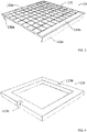
- the mechanical-acoustic transducer 13 comprises a rigid plate 131 movably mounted in the frame 11.
- the micrometric loudspeaker according to the first aspect of the invention is distinguished from flexible membrane micrometric loudspeakers.
- the electromechanical transducer 12 and the mechanical-acoustic transducer 13 are coupled together so that a stress on the electromechanical transducer 12 moves the mechanical-acoustic transducer 13 relative to the frame 11 and a corresponding movement of the mechanical-acoustic transducer 13 is converted in sound pressure.
- the electromechanical transducer 12 comprises two piezoelectric actuators 121a, 121b and two elastic blades 122a, 122b.
- Each piezoelectric actuator is associated with an elastic strip to induce, when it is electrically powered, a deformation of the elastic strip by bimetallic effect.
- each piezoelectric actuator is associated with an elastic blade so that, when an electric voltage is applied to the piezoelectric actuator, the blade deforms in bending.
- the frame 11 for its part comprises a central crosspiece 111 from which extend, integrally and opposite one another, the two elastic blades 122a, 122b.
- the two elastic blades 122a, 122b extend from the central crosspiece 111 of the frame 11 until they engage two lateral so-called coupling flanges 132a, 132b of the mechanical-acoustic transducer 13.
- each elastic blade 122a, 122b is in a so-called “embedded-guided” bending configuration.
- the elastic blades 122a, 122b deform in bending and bring with them a movement of the rigid plate 131 of the mechanical-acoustic transducer 13 in a direction substantially perpendicular to a plane main extension of the frame 11. It thus appears that the mechanical-acoustic transducer 13 is more particularly movably mounted in the frame 11 via the electromechanical transducer 12.
- the mechanical-acoustic transducer 13 further comprises at least two linearization springs 133a, 133b.
- the two linearization springs 133a, 133b each extend from one of the side coupling edges 132a, 132b of the mechanical-acoustic transducer 13 to a side edge of its rigid plate 131 which is located opposite.
- the linearization springs 133a, 133b are thus configured so as to allow, during a deformation of the elastic blades 122a, 122b, a displacement of at least part of the two lateral coupling flanges 132a, 132b towards the central crosspiece 111 of the frame 11.
- the piezoelectric actuators 121a, 121b When the piezoelectric actuators 121a, 121b are electrically powered, the elastic blades each adopt a deformation with a substantially central point of inflection and undergo longitudinal stresses, due to their recessed-guided bending configuration.
- the linearization springs 133a, 133b then make it possible to absorb at least part of these longitudinal stresses.
- the piezoelectric actuators 121a, 121b are made from PZT, which can only contract in the direction x as illustrated on the figure 7 , the piezoelectric actuators 121a, 121b are preferably arranged only on half the surface of the elastic blades 122a, 122b.
- the piezoelectric actuators 121a, 121b each extend continuously from the edge of the elastic blade 122a, 122b with which it is associated, as shown in the figure 10 , preferably over at least a quarter of the surface of said elastic strip, and preferably at most over half of this surface.
- the linearization springs 133a, 133b add, to the micrometric loudspeaker 1, a degree of freedom by allowing a displacement of at least part of the two side coupling edges 132a, 132b of the mechanical-acoustic transducer 13 towards the central crosspiece 111 of the frame 11, during the deformations of the elastic blades 122a, 122b. They thus make it possible to reduce the stresses, in particular longitudinal stresses, undergone by the elastic blades 122a, 122b; however, such constraints could be the cause of a stiffening of the elastic blades 122a, 122b, which would have the consequence of inducing a non-linear behavior of the rigid plate 131 during its displacements, or at least for certain large amplitudes of its displacements. As soon as the longitudinal stresses undergone by the elastic strips 122a, 122b are reduced, or even rendered negligible, it is understood that the performance of the micrometric loudspeaker 1 is increased.
- the micrometric loudspeaker 1 is preferably substantially symmetrical with respect to a longitudinal section plane of the central crosspiece 111 of the frame 11 which is perpendicular to the main extension plane of the frame 11.
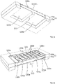
- the micrometric loudspeaker 1 can also be considered as comprising two parts superimposed on each other in a concentric manner.
- the frame 11 can be seen as consisting of two parts 11a and 11b, of which a first part 11a supports, preferably on its own, the central crosspiece 111 of the frame 11 and a second part 11b configured to house the transducer tightly therein. mechano-acoustics 13.
- the figure 7 shows a cutaway view of the loudspeaker in operation. It more particularly shows two views superimposed between them of the electromechanical transducer 12 and the mechanical-acoustic transducer 13, on the one hand in a configuration of non-deformation of the elastic blades 122a, 122b (where the piezoelectric actuators are not electrically powered), on the one hand on the other hand in a configuration of deformation of the elastic blades 122a, 122b (where the piezoelectric actuators are electrically powered), relative to the central crosspiece 111 of the frame 11, the latter remaining fixed due to the fixing of the frame 11 itself, for example on a support (not shown).
- the piezoelectric actuators 121a, 121b When the piezoelectric actuators 121a, 121b are then no longer electrically supplied, the elasticity of the elastic blades 122a, 122b makes it possible to bring the whole formed of the electromechanical transducer 12 and the mechanical-acoustic transducer 13 back to its starting position. In this so-called starting position, or equivalently of non-supply of the piezoelectric actuators 121a, 121b, the rigid plate 131 can come flush with the periphery of the face of the frame 11 which is oriented upwards in the figures.
- the micrometric loudspeaker 1 allows movements of the rigid plate 131 only in the -z direction by power supply of the piezoelectric actuators 121a, 121b, in particular because these are made from PZT, it is necessary to adding a DC voltage to the terminals of each piezoelectric actuator 121a, 121b to obtain a point of rest in the middle of the dynamics of the loudspeaker 1, to obtain an alternating movement around this operating point.
- the piezoelectric actuators operate with an electrical supply voltage range substantially between 0 and 30 V, and the DC voltage added to the terminals of each piezoelectric actuator 121a, 121b is substantially equal to 15 V.
- the figure 8 schematically shows the principle of operation of the micrometric loudspeaker 1 according to the first aspect of the invention comprising an additional degree of freedom conferred on it by the linearization springs 133a, 133b.
- the elastic blades 122a, 122b are deformed and move the rigid plate 131 by a distance ⁇ 0 along -z.
- the length of the curve of each deformed elastic blade 122a, 122b should be identical to the length of the undeformed elastic blade 122a, 122b.
- the difference between the position of the distal end of the elastic blade 122a, before and after deformation, and in the direction y, is denoted ⁇ 0 .
- This difference is authorized by the linearization spring 133a secured to the rigid plate 131 by its end opposite to that by which the linearization spring 133a is secured to the distal end of the elastic blade 122a.
- the idea is that the displacement ⁇ 0 deforms the linearization spring 133a by using the height h 0 of the lateral coupling rim 132a of the mechanical-acoustic transducer 13 as a lever arm.
- each linearization spring actuated via the lateral coupling flange, of height ho, associated with it and serving as a lever, i.e. 10 times, preferably 100 times , less than the apparent stiffness of the actuators along the axis outside the main extension plane of the frame.
- the micrometric loudspeaker 1 allows guidance of the mechanical-acoustic transducer 13 similar to that which would be authorized by the system equivalent shown on the figure 9 .
- the diagram of this figure shows a piezoelectric actuator 121a and the elastic blade 122a associated with it in a deformed state, the elastic blade 122a being linked to the rigid plate 131 by a spring representing the stiffness of the linearization spring 133a along the axis z.
- the piezoelectric actuator 121a and the elastic blade 122a as a mechanical actuator, and knowing that, according to the block diagram of the figure 9 , the characteristic of the mechanical actuator thus defined is the straight line connecting its blocked force (force generated by the actuator when the translation of its end is blocked according to z) and its free displacement (maximum displacement of the end of the actuator without load at its end), the stiffness of the spring illustrated on the figure 9 cuts the characteristic of the mechanical actuator at its operating point. For a spring as shown in the figure 9 which is quite stiff, the force corresponding to the operating point differs little from the blocked force of the mechanical actuator, which advantageously makes it possible to give the mechanical actuator a linear behavior over its operating range.
- each linearization spring 133a, 133b has a stiffness at least ten times, preferably at least a hundred times, greater than a stiffness of the elastic blades 122a, 122b.
- the additional degree of freedom conferred by the linearization springs makes it possible to reduce the non-linearities.
- the fact that the linearization springs are stiffer than the actuators means that the frequency response of the micrometric loudspeaker is not altered.
- Another characteristic reflecting this same preference in a different way consists in specifying that the elastic blades of the electromechanical transducer 12 have a first resonance frequency and the linearization springs 133a, 133b of the mechanical-acoustic transducer 13 have a second resonance frequency, the second resonant frequency being at least one hundred times, preferably at least one thousand times, greater than the first resonant frequency. It is thus ensured that the second resonant frequency is outside the desired passband reached by the micrometric loudspeaker 1, and one thus confers, on the micrometric loudspeaker 1, a wide passband for a optimized perceptible sound frequency range.
- the rigid plate 131 moves up and down and generates acoustic waves, as illustrated in the figure 10 .
- the acoustic short circuit resulting from the interference between the positive (or negative) waves created by the front of the vibrating rigid plate, and the negative (or positive) waves created by the back of this same plate, can be prevented by a deformable suspension.
- the acoustic short-circuit is prevented by using a dimension d of gap 2 between the frame 11 and the rigid plate 131, and more particularly between the inner periphery of the frame 11 and side flanges coupling 132a, 132b of the mechanical-acoustic transducer 13, such that the thermo-viscous behavior dominates in this interstice 2.
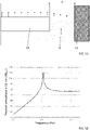
- the figure 11 shows a schematic representation of part of the mechano-acoustic transducer 13, of the frame 11 and of the gap 2 in question, on which the dimension d of the gap 2 is represented.
- the frame 11 is configured so that the mechanical-acoustic transducer 13 is located, on all sides, at an interstitial distance from the inner periphery of the frame 11 of between 1 and 100 ⁇ m, preferably between 2 and 80 ⁇ m.
- a finite element simulation can make it possible to determine, for each dimensioning of the micrometric loudspeaker 1 according to the first aspect of the invention, the interstitial distance making it possible to optimize the thermo-viscous behavior of the air in the interstice 2.
- this finite element simulation shows that the optimum dimension of the gap 2 is substantially equal to 9 ⁇ m.
- the gap 2 between the frame 11 and the mechanical-acoustic transducer 13 is thus such that, at this gap 2, the propagation of the acoustic waves is mainly dominated by thermo-viscous behavior. This avoids any acoustic short-circuit phenomenon.
- the dimensions of the micrometric loudspeaker 1 are obviously important because they influence the dimensions of the rigid plate 131 and the dimensions of the elastic blades 122a, 122b, and consequently on those of the piezoelectric actuators 121a, 121b.
- a larger loudspeaker will have a larger, heavier rigid plate 131, softer spring blades 122a, 122b and will generate more force. It will therefore have a lower resonant frequency, and therefore a wider bandwidth in the low frequencies.
- the figure 12 shows the frequency response of a micrometric loudspeaker 1 according to the first aspect of the invention, the rigid plate 131 of which has dimensions of 8 ⁇ 8 mm 2 .
- the resonance frequency of such a micrometric loudspeaker 1 is substantially equal to 1 kHz. Smaller dimensions will give a higher resonant frequency, and therefore a narrower bandwidth. However, dimensions ranging from 1 ⁇ 1 mm 2 to 10 ⁇ 10 mm 2 of the micrometric loudspeaker 1 according to the first aspect of the invention are envisaged. Dimensions ranging from 3 ⁇ 3 mm 2 to 8 ⁇ 8 mm 2 will for example be preferred for reasons of compromise between performance and size.
- the height h 0 of the side coupling flanges 132a, 132b represented on the figure 8 is optimized so that the thermo-viscous losses due to the compressed air below the rigid plate 131 is minimized.
- the thermo-viscous losses do not significantly modify the frequency response of the micrometric loudspeaker 1. This height, however, depends on the other dimensions of the micrometric loudspeaker 1. This is why, more generally, the side coupling edges 132a, 132b of the mechanical-acoustic transducer 13 extend from one of the two linearization springs 133a, 133b over a distance greater than 750 ⁇ m, preferably greater than 500 ⁇ m.
- the frequency response of the micrometric loudspeaker 1 can also be greatly affected by the thickness of the elastic blades 122a, 122b supporting the piezoelectric actuators 121a, 121b. Thinner elastic blades 122a, 122b will give a lower resonant frequency and thicker elastic blades 122a, 122b will give more force to the micrometric loudspeaker 1 and therefore a higher level of radiated pressure. A compromise is therefore preferably to be determined in order to have a low resonance frequency and a satisfactory pressure level. This dimension again depends on the other dimensions of the micrometric loudspeaker 1.
- the elastic blades 122a, 122b can have a thickness of between 1 and 100 ⁇ m, preferably between 5 and 20 ⁇ m, and for example substantially equal to 12 ⁇ m.
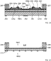
- the figures 13 to 16 give an example of a method of manufacturing a micrometric loudspeaker 1 according to an embodiment of the first aspect of the invention.
- This method advantageously implements technological steps, in particular of deposition and etching, ordinary in microelectronics. These technological steps are for example carried out from two slices of silicon (or “wafer” according to the Anglo-Saxon terminology). More particularly, as already introduced above and according to the example illustrated, two silicon wafers can be processed individually, assembled together, then the assembly can be processed in turn to obtain the micrometric loudspeaker 1 according to one embodiment of the first aspect of the invention. Nevertheless, any other conventional mechanical assembly method, than that illustrated in the figures, can be used.
- manufacturing begins with a BESOI wafer, composed of two layers of silicon separated by a layer of silicon oxide 201.
- a stack comprising a first electrode layer, a layer of a piezoelectric material, then a second electrode layer, is deposited.
- a hard mask 202 is etched on the rear face FAR1 in order to subsequently perform a deep etching step by this back side.
- the piezoelectric transducers 121a, 121b are then etched and protected by a passivation 203.
- Electrical contacts 204 allowing the electrical supply of the upper 205a, 206a and lower 205b, 206b electrodes of the piezoelectric actuators 121a, 121b and a material 207 intended to allow the bonding of the treated BESOI wafer to the second treated wafer are then deposited by the front face FAV1 of the BESOI wafer.
- the second wafer composed of two layers of silicon separated from an oxide layer 208 is intended to constitute a second part of the loudspeaker 1, and in particular the rigid plate 131 and the second part 11b of the frame 11.
- a mask hard 209 is etched on the front face FAR2 to allow the deep etching of a rear cavity 210.
- a hard mask 211 is etched on the rear face FAR2 to allow the subsequent etching of structuring patterns 130b, taking for example the form of bars of reinforcement, of the rigid plate 131.
- the two wafers are assembled together by their respective front faces FAV1 and FAV 2, in the manner illustrated in the figure 15 .
- the structuring patterns 130b of the rigid plate 131, as well as the gap d between the rigid plate 131 and the frame 11 are then etched by the rear face FAR2 of the second silicon wafer.
- the rear face FAR1 of the BESOI wafer is then etched to reach the loudspeaker 1 as illustrated on the figure 16 .
- the two elastic blades 122a, 122b comprise the same layer 120a integral with one face of the central crosspiece 111 which is oriented towards a center of the frame 11.
- Said layer 120a is made from silicon.
- the rigid plate 131 and the linearization springs 133a, 133b comprise the same layer 130a.
- a greater stiffness of the rigid plate 131 relative to a stiffness of the linearization springs 133a, 133b is due to the structuring patterns 130b that the rigid plate (131) comprises. More particularly, these structuring patterns 130b extend, from said layer 130a, over a surface of the latter defining the extent of the rigid plate 131.
- the linearization springs 133a, 133b are made up of portions 130c, 130d of said layer 130a which extend on either side of said surface. Furthermore, it appears that said layer 130a is made from silicon.
- the frame 11 comprises a perimeter, preferably closed.
- the crosspiece 111 of the frame 11 is integral with the inner periphery of the frame 11 by its two ends.
- the frame 11 is represented as having a parallelepipedic geometry, other shapes of the frame 11 are possible, whether for its inner circumference or its outer circumference. Thus, a frame 11 of annular or oblong shape can be envisaged. If necessary, the micrometric loudspeaker 1 will comprise more than two piezoelectric actuators each associated with each of a corresponding plurality of elastic blades.
Landscapes
- Engineering & Computer Science (AREA)
- Physics & Mathematics (AREA)
- Acoustics & Sound (AREA)
- Signal Processing (AREA)
- Multimedia (AREA)
- Health & Medical Sciences (AREA)
- Otolaryngology (AREA)
- Mechanical Engineering (AREA)
- Piezo-Electric Transducers For Audible Bands (AREA)
Applications Claiming Priority (1)
| Application Number | Priority Date | Filing Date | Title |
|---|---|---|---|
| FR2103908A FR3122023B1 (fr) | 2021-04-15 | 2021-04-15 | Haut-parleur micrométrique |
Publications (2)
| Publication Number | Publication Date |
|---|---|
| EP4075422A1 true EP4075422A1 (de) | 2022-10-19 |
| EP4075422B1 EP4075422B1 (de) | 2024-07-17 |
Family
ID=76034832
Family Applications (1)
| Application Number | Title | Priority Date | Filing Date |
|---|---|---|---|
| EP22168299.0A Active EP4075422B1 (de) | 2021-04-15 | 2022-04-14 | Mikrometrischer lautsprecher |
Country Status (3)
| Country | Link |
|---|---|
| US (1) | US11785391B2 (de) |
| EP (1) | EP4075422B1 (de) |
| FR (1) | FR3122023B1 (de) |
Families Citing this family (1)
| Publication number | Priority date | Publication date | Assignee | Title |
|---|---|---|---|---|
| SE2251545A1 (en) * | 2022-12-22 | 2024-04-16 | Myvox Ab | A mems-based micro speaker device and system |
Citations (3)
| Publication number | Priority date | Publication date | Assignee | Title |
|---|---|---|---|---|
| US20120057730A1 (en) | 2009-05-25 | 2012-03-08 | Akiko Fujise | Piezoelectric acoustic transducer |
| US20170094418A1 (en) | 2014-05-14 | 2017-03-30 | USound GmbH | MEMS Loudspeaker Having an Actuator Structure and a Diaphragm Spaced Apart Therefrom |
| CN111918179A (zh) | 2020-07-10 | 2020-11-10 | 瑞声科技(南京)有限公司 | 发声装置及具有其的电子设备 |
Family Cites Families (2)
| Publication number | Priority date | Publication date | Assignee | Title |
|---|---|---|---|---|
| CN103477656B (zh) * | 2012-02-15 | 2018-04-27 | 松下知识产权经营株式会社 | 扬声器 |
| FR3090613B1 (fr) | 2018-12-20 | 2021-01-22 | Commissariat Energie Atomique | Articulation pour systemes micro et nanoelectromecaniques a deplacement hors-plan offrant une non-linearite reduite |
-
2021
- 2021-04-15 FR FR2103908A patent/FR3122023B1/fr active Active
-
2022
- 2022-04-14 EP EP22168299.0A patent/EP4075422B1/de active Active
- 2022-04-15 US US17/721,950 patent/US11785391B2/en active Active
Patent Citations (3)
| Publication number | Priority date | Publication date | Assignee | Title |
|---|---|---|---|---|
| US20120057730A1 (en) | 2009-05-25 | 2012-03-08 | Akiko Fujise | Piezoelectric acoustic transducer |
| US20170094418A1 (en) | 2014-05-14 | 2017-03-30 | USound GmbH | MEMS Loudspeaker Having an Actuator Structure and a Diaphragm Spaced Apart Therefrom |
| CN111918179A (zh) | 2020-07-10 | 2020-11-10 | 瑞声科技(南京)有限公司 | 发声装置及具有其的电子设备 |
Also Published As
| Publication number | Publication date |
|---|---|
| US11785391B2 (en) | 2023-10-10 |
| EP4075422B1 (de) | 2024-07-17 |
| US20220337954A1 (en) | 2022-10-20 |
| FR3122023A1 (fr) | 2022-10-21 |
| FR3122023B1 (fr) | 2023-12-29 |
Similar Documents
| Publication | Publication Date | Title |
|---|---|---|
| EP2410768B1 (de) | Akustischer Druckimpuls-Generator vom Typ MEMS | |
| EP1698041B1 (de) | Elektrostatische steuereinrichtung | |
| EP3975584B1 (de) | Verfahren zur herstellung eines elektroakustischen transducers | |
| EP3070963B1 (de) | Mems und/oder nems drucksensor mit verbesserten leistungen und dynamisches mikrofon mit einem solchen sensor. | |
| CN103121657A (zh) | 微机电系统及其制造方法 | |
| EP3257808B1 (de) | Mikroelektromechanische und/oder nanoelektromechanische vorrichtung mit bewegung ausserhalb der ebene, die mit kapazitiven mitteln zur änderung der oberfläche ausgestattet ist | |
| EP4075422B1 (de) | Mikrometrischer lautsprecher | |
| EP1902453B1 (de) | Kapazitive vorrichtung mit optimiertem kapazitivem volumen | |
| EP3975588B1 (de) | Verfahren zur herstellung eines elektroakustischen transducers | |
| FR3013935B1 (fr) | Film transducteur electro-actif de son ayant une surface structuree | |
| FR3033468A1 (fr) | Dispositif a membranes actionnables et haut-parleur digital comportant au moins un tel dispositif | |
| EP3743951B1 (de) | Verfahren zur gestaltung und herstellung einer vorrichtung aus einem mikrofabrizierten elementenetzwerk | |
| EP3391664A1 (de) | Akustische membran für einen lautsprecher und entsprechender lautsprecher | |
| EP4400471B1 (de) | Elektromechanisches system mit kapazitiven mess- oder betätigungsmitteln | |
| FR2737019A1 (fr) | Microelements de balayage pour systeme optique | |
| EP4047954B1 (de) | Mems-lautsprecher und verfahren zur herstellung eines solchen lautsprechers | |
| EP4221256A1 (de) | Verfahren zur herstellung eines rauscharmen elektroakustischen wandlers | |
| Dagher et al. | First MEMS Microphone Based on Capacitive Transduction in Vacuum | |
| EP3828943A1 (de) | Mechanisches mikrosystem und entsprechendes herstellungsverfahren | |
| EP4657890A1 (de) | Elektromechanisches system mit einem beweglichen element mit einer öffnung | |
| FR3143256A1 (fr) | Elément actif piézoélectrique pour système électromécanique | |
| FR3131291A1 (fr) | Procédé de fonctionnalisation d’une membrane d’un capteur électromécanique résonant | |
| EP4576067A1 (de) | Vorrichtung zur wiederherstellung eines akustischen nachhalleffekts mit einer mems-feder | |
| FR3160483A1 (fr) | Dispositif haptique mid-air avec fonction de récupération d’énergie et procédé de fabrication dudit dispositif haptique | |
| FR3090206A1 (fr) | Actionneur électromécanique, bouton vibrotactile et hautparleur surfacique comportant un tel actionneur électromécanique |
Legal Events
| Date | Code | Title | Description |
|---|---|---|---|
| PUAI | Public reference made under article 153(3) epc to a published international application that has entered the european phase |
Free format text: ORIGINAL CODE: 0009012 |
|
| STAA | Information on the status of an ep patent application or granted ep patent |
Free format text: STATUS: REQUEST FOR EXAMINATION WAS MADE |
|
| 17P | Request for examination filed |
Effective date: 20220414 |
|
| AK | Designated contracting states |
Kind code of ref document: A1 Designated state(s): AL AT BE BG CH CY CZ DE DK EE ES FI FR GB GR HR HU IE IS IT LI LT LU LV MC MK MT NL NO PL PT RO RS SE SI SK SM TR |
|
| GRAP | Despatch of communication of intention to grant a patent |
Free format text: ORIGINAL CODE: EPIDOSNIGR1 |
|
| STAA | Information on the status of an ep patent application or granted ep patent |
Free format text: STATUS: GRANT OF PATENT IS INTENDED |
|
| INTG | Intention to grant announced |
Effective date: 20240221 |
|
| GRAS | Grant fee paid |
Free format text: ORIGINAL CODE: EPIDOSNIGR3 |
|
| GRAA | (expected) grant |
Free format text: ORIGINAL CODE: 0009210 |
|
| STAA | Information on the status of an ep patent application or granted ep patent |
Free format text: STATUS: THE PATENT HAS BEEN GRANTED |
|
| AK | Designated contracting states |
Kind code of ref document: B1 Designated state(s): AL AT BE BG CH CY CZ DE DK EE ES FI FR GB GR HR HU IE IS IT LI LT LU LV MC MK MT NL NO PL PT RO RS SE SI SK SM TR |
|
| REG | Reference to a national code |
Ref country code: CH Ref legal event code: EP |
|
| REG | Reference to a national code |
Ref country code: DE Ref legal event code: R096 Ref document number: 602022004561 Country of ref document: DE |
|
| REG | Reference to a national code |
Ref country code: IE Ref legal event code: FG4D Free format text: LANGUAGE OF EP DOCUMENT: FRENCH |
|
| RAP4 | Party data changed (patent owner data changed or rights of a patent transferred) |
Owner name: UNIVERSITE DU MANS Owner name: CENTRE NATIONAL DE LA RECHERCHE SCIENTIFIQUE Owner name: COMMISSARIAT A L'ENERGIE ATOMIQUE ET AUX ENERGIESALTERNATIVES |
|
| REG | Reference to a national code |
Ref country code: LT Ref legal event code: MG9D |
|
| REG | Reference to a national code |
Ref country code: NL Ref legal event code: MP Effective date: 20240717 |
|
| PG25 | Lapsed in a contracting state [announced via postgrant information from national office to epo] |
Ref country code: PT Free format text: LAPSE BECAUSE OF FAILURE TO SUBMIT A TRANSLATION OF THE DESCRIPTION OR TO PAY THE FEE WITHIN THE PRESCRIBED TIME-LIMIT Effective date: 20241118 |
|
| REG | Reference to a national code |
Ref country code: AT Ref legal event code: MK05 Ref document number: 1704915 Country of ref document: AT Kind code of ref document: T Effective date: 20240717 |
|
| PG25 | Lapsed in a contracting state [announced via postgrant information from national office to epo] |
Ref country code: NL Free format text: LAPSE BECAUSE OF FAILURE TO SUBMIT A TRANSLATION OF THE DESCRIPTION OR TO PAY THE FEE WITHIN THE PRESCRIBED TIME-LIMIT Effective date: 20240717 |
|
| PG25 | Lapsed in a contracting state [announced via postgrant information from national office to epo] |
Ref country code: PT Free format text: LAPSE BECAUSE OF FAILURE TO SUBMIT A TRANSLATION OF THE DESCRIPTION OR TO PAY THE FEE WITHIN THE PRESCRIBED TIME-LIMIT Effective date: 20241118 Ref country code: NL Free format text: LAPSE BECAUSE OF FAILURE TO SUBMIT A TRANSLATION OF THE DESCRIPTION OR TO PAY THE FEE WITHIN THE PRESCRIBED TIME-LIMIT Effective date: 20240717 |
|
| PG25 | Lapsed in a contracting state [announced via postgrant information from national office to epo] |
Ref country code: NO Free format text: LAPSE BECAUSE OF FAILURE TO SUBMIT A TRANSLATION OF THE DESCRIPTION OR TO PAY THE FEE WITHIN THE PRESCRIBED TIME-LIMIT Effective date: 20241017 |
|
| PG25 | Lapsed in a contracting state [announced via postgrant information from national office to epo] |
Ref country code: FI Free format text: LAPSE BECAUSE OF FAILURE TO SUBMIT A TRANSLATION OF THE DESCRIPTION OR TO PAY THE FEE WITHIN THE PRESCRIBED TIME-LIMIT Effective date: 20240717 Ref country code: PL Free format text: LAPSE BECAUSE OF FAILURE TO SUBMIT A TRANSLATION OF THE DESCRIPTION OR TO PAY THE FEE WITHIN THE PRESCRIBED TIME-LIMIT Effective date: 20240717 Ref country code: GR Free format text: LAPSE BECAUSE OF FAILURE TO SUBMIT A TRANSLATION OF THE DESCRIPTION OR TO PAY THE FEE WITHIN THE PRESCRIBED TIME-LIMIT Effective date: 20241018 |
|
| PG25 | Lapsed in a contracting state [announced via postgrant information from national office to epo] |
Ref country code: BG Free format text: LAPSE BECAUSE OF FAILURE TO SUBMIT A TRANSLATION OF THE DESCRIPTION OR TO PAY THE FEE WITHIN THE PRESCRIBED TIME-LIMIT Effective date: 20240717 |
|
| PG25 | Lapsed in a contracting state [announced via postgrant information from national office to epo] |
Ref country code: LV Free format text: LAPSE BECAUSE OF FAILURE TO SUBMIT A TRANSLATION OF THE DESCRIPTION OR TO PAY THE FEE WITHIN THE PRESCRIBED TIME-LIMIT Effective date: 20240717 |
|
| PG25 | Lapsed in a contracting state [announced via postgrant information from national office to epo] |
Ref country code: AT Free format text: LAPSE BECAUSE OF FAILURE TO SUBMIT A TRANSLATION OF THE DESCRIPTION OR TO PAY THE FEE WITHIN THE PRESCRIBED TIME-LIMIT Effective date: 20240717 Ref country code: IS Free format text: LAPSE BECAUSE OF FAILURE TO SUBMIT A TRANSLATION OF THE DESCRIPTION OR TO PAY THE FEE WITHIN THE PRESCRIBED TIME-LIMIT Effective date: 20241117 |
|
| PG25 | Lapsed in a contracting state [announced via postgrant information from national office to epo] |
Ref country code: HR Free format text: LAPSE BECAUSE OF FAILURE TO SUBMIT A TRANSLATION OF THE DESCRIPTION OR TO PAY THE FEE WITHIN THE PRESCRIBED TIME-LIMIT Effective date: 20240717 |
|
| PG25 | Lapsed in a contracting state [announced via postgrant information from national office to epo] |
Ref country code: ES Free format text: LAPSE BECAUSE OF FAILURE TO SUBMIT A TRANSLATION OF THE DESCRIPTION OR TO PAY THE FEE WITHIN THE PRESCRIBED TIME-LIMIT Effective date: 20240717 Ref country code: RS Free format text: LAPSE BECAUSE OF FAILURE TO SUBMIT A TRANSLATION OF THE DESCRIPTION OR TO PAY THE FEE WITHIN THE PRESCRIBED TIME-LIMIT Effective date: 20241017 |
|
| PG25 | Lapsed in a contracting state [announced via postgrant information from national office to epo] |
Ref country code: RS Free format text: LAPSE BECAUSE OF FAILURE TO SUBMIT A TRANSLATION OF THE DESCRIPTION OR TO PAY THE FEE WITHIN THE PRESCRIBED TIME-LIMIT Effective date: 20241017 Ref country code: PL Free format text: LAPSE BECAUSE OF FAILURE TO SUBMIT A TRANSLATION OF THE DESCRIPTION OR TO PAY THE FEE WITHIN THE PRESCRIBED TIME-LIMIT Effective date: 20240717 Ref country code: NO Free format text: LAPSE BECAUSE OF FAILURE TO SUBMIT A TRANSLATION OF THE DESCRIPTION OR TO PAY THE FEE WITHIN THE PRESCRIBED TIME-LIMIT Effective date: 20241017 Ref country code: LV Free format text: LAPSE BECAUSE OF FAILURE TO SUBMIT A TRANSLATION OF THE DESCRIPTION OR TO PAY THE FEE WITHIN THE PRESCRIBED TIME-LIMIT Effective date: 20240717 Ref country code: IS Free format text: LAPSE BECAUSE OF FAILURE TO SUBMIT A TRANSLATION OF THE DESCRIPTION OR TO PAY THE FEE WITHIN THE PRESCRIBED TIME-LIMIT Effective date: 20241117 Ref country code: HR Free format text: LAPSE BECAUSE OF FAILURE TO SUBMIT A TRANSLATION OF THE DESCRIPTION OR TO PAY THE FEE WITHIN THE PRESCRIBED TIME-LIMIT Effective date: 20240717 Ref country code: GR Free format text: LAPSE BECAUSE OF FAILURE TO SUBMIT A TRANSLATION OF THE DESCRIPTION OR TO PAY THE FEE WITHIN THE PRESCRIBED TIME-LIMIT Effective date: 20241018 Ref country code: FI Free format text: LAPSE BECAUSE OF FAILURE TO SUBMIT A TRANSLATION OF THE DESCRIPTION OR TO PAY THE FEE WITHIN THE PRESCRIBED TIME-LIMIT Effective date: 20240717 Ref country code: ES Free format text: LAPSE BECAUSE OF FAILURE TO SUBMIT A TRANSLATION OF THE DESCRIPTION OR TO PAY THE FEE WITHIN THE PRESCRIBED TIME-LIMIT Effective date: 20240717 Ref country code: BG Free format text: LAPSE BECAUSE OF FAILURE TO SUBMIT A TRANSLATION OF THE DESCRIPTION OR TO PAY THE FEE WITHIN THE PRESCRIBED TIME-LIMIT Effective date: 20240717 Ref country code: AT Free format text: LAPSE BECAUSE OF FAILURE TO SUBMIT A TRANSLATION OF THE DESCRIPTION OR TO PAY THE FEE WITHIN THE PRESCRIBED TIME-LIMIT Effective date: 20240717 |
|
| PG25 | Lapsed in a contracting state [announced via postgrant information from national office to epo] |
Ref country code: RO Free format text: LAPSE BECAUSE OF FAILURE TO SUBMIT A TRANSLATION OF THE DESCRIPTION OR TO PAY THE FEE WITHIN THE PRESCRIBED TIME-LIMIT Effective date: 20240717 Ref country code: SM Free format text: LAPSE BECAUSE OF FAILURE TO SUBMIT A TRANSLATION OF THE DESCRIPTION OR TO PAY THE FEE WITHIN THE PRESCRIBED TIME-LIMIT Effective date: 20240717 Ref country code: DK Free format text: LAPSE BECAUSE OF FAILURE TO SUBMIT A TRANSLATION OF THE DESCRIPTION OR TO PAY THE FEE WITHIN THE PRESCRIBED TIME-LIMIT Effective date: 20240717 |
|
| REG | Reference to a national code |
Ref country code: DE Ref legal event code: R097 Ref document number: 602022004561 Country of ref document: DE |
|
| PG25 | Lapsed in a contracting state [announced via postgrant information from national office to epo] |
Ref country code: EE Free format text: LAPSE BECAUSE OF FAILURE TO SUBMIT A TRANSLATION OF THE DESCRIPTION OR TO PAY THE FEE WITHIN THE PRESCRIBED TIME-LIMIT Effective date: 20240717 |
|
| PG25 | Lapsed in a contracting state [announced via postgrant information from national office to epo] |
Ref country code: CZ Free format text: LAPSE BECAUSE OF FAILURE TO SUBMIT A TRANSLATION OF THE DESCRIPTION OR TO PAY THE FEE WITHIN THE PRESCRIBED TIME-LIMIT Effective date: 20240717 |
|
| PG25 | Lapsed in a contracting state [announced via postgrant information from national office to epo] |
Ref country code: SK Free format text: LAPSE BECAUSE OF FAILURE TO SUBMIT A TRANSLATION OF THE DESCRIPTION OR TO PAY THE FEE WITHIN THE PRESCRIBED TIME-LIMIT Effective date: 20240717 |
|
| PLBE | No opposition filed within time limit |
Free format text: ORIGINAL CODE: 0009261 |
|
| STAA | Information on the status of an ep patent application or granted ep patent |
Free format text: STATUS: NO OPPOSITION FILED WITHIN TIME LIMIT |
|
| 26N | No opposition filed |
Effective date: 20250422 |
|
| PGFP | Annual fee paid to national office [announced via postgrant information from national office to epo] |
Ref country code: DE Payment date: 20250417 Year of fee payment: 4 |
|
| PGFP | Annual fee paid to national office [announced via postgrant information from national office to epo] |
Ref country code: FR Payment date: 20250422 Year of fee payment: 4 |
|
| PG25 | Lapsed in a contracting state [announced via postgrant information from national office to epo] |
Ref country code: SE Free format text: LAPSE BECAUSE OF FAILURE TO SUBMIT A TRANSLATION OF THE DESCRIPTION OR TO PAY THE FEE WITHIN THE PRESCRIBED TIME-LIMIT Effective date: 20240717 |
|
| REG | Reference to a national code |
Ref country code: CH Ref legal event code: H13 Free format text: ST27 STATUS EVENT CODE: U-0-0-H10-H13 (AS PROVIDED BY THE NATIONAL OFFICE) Effective date: 20251125 |
|
| PG25 | Lapsed in a contracting state [announced via postgrant information from national office to epo] |
Ref country code: LU Free format text: LAPSE BECAUSE OF NON-PAYMENT OF DUE FEES Effective date: 20250414 |
|
| PG25 | Lapsed in a contracting state [announced via postgrant information from national office to epo] |
Ref country code: MC Free format text: LAPSE BECAUSE OF FAILURE TO SUBMIT A TRANSLATION OF THE DESCRIPTION OR TO PAY THE FEE WITHIN THE PRESCRIBED TIME-LIMIT Effective date: 20240717 |
|
| REG | Reference to a national code |
Ref country code: BE Ref legal event code: MM Effective date: 20250430 |
|
| PG25 | Lapsed in a contracting state [announced via postgrant information from national office to epo] |
Ref country code: BE Free format text: LAPSE BECAUSE OF NON-PAYMENT OF DUE FEES Effective date: 20250430 |
|
| PG25 | Lapsed in a contracting state [announced via postgrant information from national office to epo] |
Ref country code: CH Free format text: LAPSE BECAUSE OF NON-PAYMENT OF DUE FEES Effective date: 20250430 |
|
| PG25 | Lapsed in a contracting state [announced via postgrant information from national office to epo] |
Ref country code: IT Free format text: LAPSE BECAUSE OF FAILURE TO SUBMIT A TRANSLATION OF THE DESCRIPTION OR TO PAY THE FEE WITHIN THE PRESCRIBED TIME-LIMIT Effective date: 20240717 |