EP3414050B1 - Trennmaschine - Google Patents
Trennmaschine Download PDFInfo
- Publication number
- EP3414050B1 EP3414050B1 EP17704453.4A EP17704453A EP3414050B1 EP 3414050 B1 EP3414050 B1 EP 3414050B1 EP 17704453 A EP17704453 A EP 17704453A EP 3414050 B1 EP3414050 B1 EP 3414050B1
- Authority
- EP
- European Patent Office
- Prior art keywords
- workpiece
- cutting
- plane
- separating cuts
- cutting machine
- Prior art date
- Legal status (The legal status is an assumption and is not a legal conclusion. Google has not performed a legal analysis and makes no representation as to the accuracy of the status listed.)
- Active
Links
Images







Classifications
-
- B—PERFORMING OPERATIONS; TRANSPORTING
- B24—GRINDING; POLISHING
- B24B—MACHINES, DEVICES, OR PROCESSES FOR GRINDING OR POLISHING; DRESSING OR CONDITIONING OF ABRADING SURFACES; FEEDING OF GRINDING, POLISHING, OR LAPPING AGENTS
- B24B27/00—Other grinding machines or devices
- B24B27/06—Grinders for cutting-off
-
- B—PERFORMING OPERATIONS; TRANSPORTING
- B23—MACHINE TOOLS; METAL-WORKING NOT OTHERWISE PROVIDED FOR
- B23D—PLANING; SLOTTING; SHEARING; BROACHING; SAWING; FILING; SCRAPING; LIKE OPERATIONS FOR WORKING METAL BY REMOVING MATERIAL, NOT OTHERWISE PROVIDED FOR
- B23D45/00—Sawing machines or sawing devices with circular saw blades or with friction saw discs
- B23D45/02—Sawing machines or sawing devices with circular saw blades or with friction saw discs with a circular saw blade or the stock mounted on a carriage
-
- B—PERFORMING OPERATIONS; TRANSPORTING
- B23—MACHINE TOOLS; METAL-WORKING NOT OTHERWISE PROVIDED FOR
- B23D—PLANING; SLOTTING; SHEARING; BROACHING; SAWING; FILING; SCRAPING; LIKE OPERATIONS FOR WORKING METAL BY REMOVING MATERIAL, NOT OTHERWISE PROVIDED FOR
- B23D59/00—Accessories specially designed for sawing machines or sawing devices
- B23D59/001—Measuring or control devices, e.g. for automatic control of work feed pressure on band saw blade
-
- B—PERFORMING OPERATIONS; TRANSPORTING
- B23—MACHINE TOOLS; METAL-WORKING NOT OTHERWISE PROVIDED FOR
- B23Q—DETAILS, COMPONENTS, OR ACCESSORIES FOR MACHINE TOOLS, e.g. ARRANGEMENTS FOR COPYING OR CONTROLLING; MACHINE TOOLS IN GENERAL CHARACTERISED BY THE CONSTRUCTION OF PARTICULAR DETAILS OR COMPONENTS; COMBINATIONS OR ASSOCIATIONS OF METAL-WORKING MACHINES, NOT DIRECTED TO A PARTICULAR RESULT
- B23Q1/00—Members which are comprised in the general build-up of a form of machine, particularly relatively large fixed members
- B23Q1/25—Movable or adjustable work or tool supports
- B23Q1/44—Movable or adjustable work or tool supports using particular mechanisms
- B23Q1/56—Movable or adjustable work or tool supports using particular mechanisms with sliding pairs only, the sliding pairs being the first two elements of the mechanism
- B23Q1/60—Movable or adjustable work or tool supports using particular mechanisms with sliding pairs only, the sliding pairs being the first two elements of the mechanism two sliding pairs only, the sliding pairs being the first two elements of the mechanism
- B23Q1/62—Movable or adjustable work or tool supports using particular mechanisms with sliding pairs only, the sliding pairs being the first two elements of the mechanism two sliding pairs only, the sliding pairs being the first two elements of the mechanism with perpendicular axes, e.g. cross-slides
- B23Q1/621—Movable or adjustable work or tool supports using particular mechanisms with sliding pairs only, the sliding pairs being the first two elements of the mechanism two sliding pairs only, the sliding pairs being the first two elements of the mechanism with perpendicular axes, e.g. cross-slides a single sliding pair followed perpendicularly by a single sliding pair
- B23Q1/623—Movable or adjustable work or tool supports using particular mechanisms with sliding pairs only, the sliding pairs being the first two elements of the mechanism two sliding pairs only, the sliding pairs being the first two elements of the mechanism with perpendicular axes, e.g. cross-slides a single sliding pair followed perpendicularly by a single sliding pair followed perpendicularly by a single rotating pair
-
- B—PERFORMING OPERATIONS; TRANSPORTING
- B23—MACHINE TOOLS; METAL-WORKING NOT OTHERWISE PROVIDED FOR
- B23Q—DETAILS, COMPONENTS, OR ACCESSORIES FOR MACHINE TOOLS, e.g. ARRANGEMENTS FOR COPYING OR CONTROLLING; MACHINE TOOLS IN GENERAL CHARACTERISED BY THE CONSTRUCTION OF PARTICULAR DETAILS OR COMPONENTS; COMBINATIONS OR ASSOCIATIONS OF METAL-WORKING MACHINES, NOT DIRECTED TO A PARTICULAR RESULT
- B23Q1/00—Members which are comprised in the general build-up of a form of machine, particularly relatively large fixed members
- B23Q1/25—Movable or adjustable work or tool supports
- B23Q1/44—Movable or adjustable work or tool supports using particular mechanisms
- B23Q1/56—Movable or adjustable work or tool supports using particular mechanisms with sliding pairs only, the sliding pairs being the first two elements of the mechanism
- B23Q1/60—Movable or adjustable work or tool supports using particular mechanisms with sliding pairs only, the sliding pairs being the first two elements of the mechanism two sliding pairs only, the sliding pairs being the first two elements of the mechanism
- B23Q1/62—Movable or adjustable work or tool supports using particular mechanisms with sliding pairs only, the sliding pairs being the first two elements of the mechanism two sliding pairs only, the sliding pairs being the first two elements of the mechanism with perpendicular axes, e.g. cross-slides
- B23Q1/621—Movable or adjustable work or tool supports using particular mechanisms with sliding pairs only, the sliding pairs being the first two elements of the mechanism two sliding pairs only, the sliding pairs being the first two elements of the mechanism with perpendicular axes, e.g. cross-slides a single sliding pair followed perpendicularly by a single sliding pair
- B23Q1/625—Movable or adjustable work or tool supports using particular mechanisms with sliding pairs only, the sliding pairs being the first two elements of the mechanism two sliding pairs only, the sliding pairs being the first two elements of the mechanism with perpendicular axes, e.g. cross-slides a single sliding pair followed perpendicularly by a single sliding pair followed parallelly by a single rotating pair
-
- B—PERFORMING OPERATIONS; TRANSPORTING
- B24—GRINDING; POLISHING
- B24B—MACHINES, DEVICES, OR PROCESSES FOR GRINDING OR POLISHING; DRESSING OR CONDITIONING OF ABRADING SURFACES; FEEDING OF GRINDING, POLISHING, OR LAPPING AGENTS
- B24B41/00—Component parts such as frames, beds, carriages, headstocks
- B24B41/06—Work supports, e.g. adjustable steadies
-
- B—PERFORMING OPERATIONS; TRANSPORTING
- B24—GRINDING; POLISHING
- B24B—MACHINES, DEVICES, OR PROCESSES FOR GRINDING OR POLISHING; DRESSING OR CONDITIONING OF ABRADING SURFACES; FEEDING OF GRINDING, POLISHING, OR LAPPING AGENTS
- B24B49/00—Measuring or gauging equipment for controlling the feed movement of the grinding tool or work; Arrangements of indicating or measuring equipment, e.g. for indicating the start of the grinding operation
- B24B49/12—Measuring or gauging equipment for controlling the feed movement of the grinding tool or work; Arrangements of indicating or measuring equipment, e.g. for indicating the start of the grinding operation involving optical means
-
- B—PERFORMING OPERATIONS; TRANSPORTING
- B25—HAND TOOLS; PORTABLE POWER-DRIVEN TOOLS; MANIPULATORS
- B25J—MANIPULATORS; CHAMBERS PROVIDED WITH MANIPULATION DEVICES
- B25J19/00—Accessories fitted to manipulators, e.g. for monitoring, for viewing; Safety devices combined with or specially adapted for use in connection with manipulators
- B25J19/0025—Means for supplying energy to the end effector
- B25J19/0045—Contactless power transmission, e.g. by magnetic induction
-
- B—PERFORMING OPERATIONS; TRANSPORTING
- B25—HAND TOOLS; PORTABLE POWER-DRIVEN TOOLS; MANIPULATORS
- B25J—MANIPULATORS; CHAMBERS PROVIDED WITH MANIPULATION DEVICES
- B25J9/00—Program-controlled manipulators
- B25J9/16—Program controls
- B25J9/1656—Program controls characterised by programming, planning systems for manipulators
- B25J9/1661—Program controls characterised by programming, planning systems for manipulators characterised by task planning, object-oriented languages
-
- B—PERFORMING OPERATIONS; TRANSPORTING
- B25—HAND TOOLS; PORTABLE POWER-DRIVEN TOOLS; MANIPULATORS
- B25J—MANIPULATORS; CHAMBERS PROVIDED WITH MANIPULATION DEVICES
- B25J9/00—Program-controlled manipulators
- B25J9/16—Program controls
- B25J9/1679—Program controls characterised by the tasks executed
- B25J9/1682—Dual arm manipulator; Coordination of several manipulators
-
- B—PERFORMING OPERATIONS; TRANSPORTING
- B25—HAND TOOLS; PORTABLE POWER-DRIVEN TOOLS; MANIPULATORS
- B25J—MANIPULATORS; CHAMBERS PROVIDED WITH MANIPULATION DEVICES
- B25J9/00—Program-controlled manipulators
- B25J9/16—Program controls
- B25J9/1679—Program controls characterised by the tasks executed
- B25J9/1692—Calibration of manipulator
-
- G—PHYSICS
- G05—CONTROLLING; REGULATING
- G05B—CONTROL OR REGULATING SYSTEMS IN GENERAL; FUNCTIONAL ELEMENTS OF SUCH SYSTEMS; MONITORING OR TESTING ARRANGEMENTS FOR SUCH SYSTEMS OR ELEMENTS
- G05B13/00—Adaptive control systems, i.e. systems automatically adjusting themselves to have a performance which is optimum according to some preassigned criterion
- G05B13/02—Adaptive control systems, i.e. systems automatically adjusting themselves to have a performance which is optimum according to some preassigned criterion electric
- G05B13/04—Adaptive control systems, i.e. systems automatically adjusting themselves to have a performance which is optimum according to some preassigned criterion electric involving the use of models or simulators
- G05B13/048—Adaptive control systems, i.e. systems automatically adjusting themselves to have a performance which is optimum according to some preassigned criterion electric involving the use of models or simulators using a predictor
-
- G—PHYSICS
- G05—CONTROLLING; REGULATING
- G05B—CONTROL OR REGULATING SYSTEMS IN GENERAL; FUNCTIONAL ELEMENTS OF SUCH SYSTEMS; MONITORING OR TESTING ARRANGEMENTS FOR SUCH SYSTEMS OR ELEMENTS
- G05B19/00—Program-control systems
- G05B19/02—Program-control systems electric
- G05B19/418—Total factory control, i.e. centrally controlling a plurality of machines, e.g. direct or distributed numerical control [DNC], flexible manufacturing systems [FMS], integrated manufacturing systems [IMS] or computer integrated manufacturing [CIM]
- G05B19/41865—Total factory control, i.e. centrally controlling a plurality of machines, e.g. direct or distributed numerical control [DNC], flexible manufacturing systems [FMS], integrated manufacturing systems [IMS] or computer integrated manufacturing [CIM] characterised by job scheduling, process planning, material flow
-
- G—PHYSICS
- G05—CONTROLLING; REGULATING
- G05D—SYSTEMS FOR CONTROLLING OR REGULATING NON-ELECTRIC VARIABLES
- G05D1/00—Control of position, course, altitude or attitude of land, water, air or space vehicles, e.g. using automatic pilots
- G05D1/02—Control of position or course in two dimensions
- G05D1/021—Control of position or course in two dimensions specially adapted to land vehicles
- G05D1/0287—Control of position or course in two dimensions specially adapted to land vehicles involving a plurality of land vehicles, e.g. fleet or convoy travelling
- G05D1/0291—Fleet control
- G05D1/0297—Fleet control by controlling means in a control room
-
- G—PHYSICS
- G06—COMPUTING OR CALCULATING; COUNTING
- G06F—ELECTRIC DIGITAL DATA PROCESSING
- G06F9/00—Arrangements for program control, e.g. control units
- G06F9/06—Arrangements for program control, e.g. control units using stored programs, i.e. using an internal store of processing equipment to receive or retain programs
- G06F9/46—Multiprogramming arrangements
- G06F9/48—Program initiating; Program switching, e.g. by interrupt
- G06F9/4806—Task transfer initiation or dispatching
- G06F9/4843—Task transfer initiation or dispatching by program, e.g. task dispatcher, supervisor, operating system
- G06F9/4881—Scheduling strategies for dispatcher, e.g. round robin, multi-level priority queues
-
- G—PHYSICS
- G06—COMPUTING OR CALCULATING; COUNTING
- G06N—COMPUTING ARRANGEMENTS BASED ON SPECIFIC COMPUTATIONAL MODELS
- G06N10/00—Quantum computing, i.e. information processing based on quantum-mechanical phenomena
- G06N10/60—Quantum algorithms, e.g. based on quantum optimisation, quantum Fourier or Hadamard transforms
-
- G—PHYSICS
- G06—COMPUTING OR CALCULATING; COUNTING
- G06N—COMPUTING ARRANGEMENTS BASED ON SPECIFIC COMPUTATIONAL MODELS
- G06N10/00—Quantum computing, i.e. information processing based on quantum-mechanical phenomena
- G06N10/80—Quantum programming, e.g. interfaces, languages or software-development kits for creating or handling programs capable of running on quantum computers; Platforms for simulating or accessing quantum computers, e.g. cloud-based quantum computing
-
- G—PHYSICS
- G06—COMPUTING OR CALCULATING; COUNTING
- G06N—COMPUTING ARRANGEMENTS BASED ON SPECIFIC COMPUTATIONAL MODELS
- G06N20/00—Machine learning
-
- G—PHYSICS
- G06—COMPUTING OR CALCULATING; COUNTING
- G06N—COMPUTING ARRANGEMENTS BASED ON SPECIFIC COMPUTATIONAL MODELS
- G06N5/00—Computing arrangements using knowledge-based models
- G06N5/04—Inference or reasoning models
- G06N5/043—Distributed expert systems; Blackboards
-
- G—PHYSICS
- G06—COMPUTING OR CALCULATING; COUNTING
- G06Q—INFORMATION AND COMMUNICATION TECHNOLOGY [ICT] SPECIALLY ADAPTED FOR ADMINISTRATIVE, COMMERCIAL, FINANCIAL, MANAGERIAL OR SUPERVISORY PURPOSES; SYSTEMS OR METHODS SPECIALLY ADAPTED FOR ADMINISTRATIVE, COMMERCIAL, FINANCIAL, MANAGERIAL OR SUPERVISORY PURPOSES, NOT OTHERWISE PROVIDED FOR
- G06Q10/00—Administration; Management
- G06Q10/04—Forecasting or optimisation specially adapted for administrative or management purposes, e.g. linear programming or "cutting stock problem"
-
- G—PHYSICS
- G06—COMPUTING OR CALCULATING; COUNTING
- G06Q—INFORMATION AND COMMUNICATION TECHNOLOGY [ICT] SPECIALLY ADAPTED FOR ADMINISTRATIVE, COMMERCIAL, FINANCIAL, MANAGERIAL OR SUPERVISORY PURPOSES; SYSTEMS OR METHODS SPECIALLY ADAPTED FOR ADMINISTRATIVE, COMMERCIAL, FINANCIAL, MANAGERIAL OR SUPERVISORY PURPOSES, NOT OTHERWISE PROVIDED FOR
- G06Q10/00—Administration; Management
- G06Q10/06—Resources, workflows, human or project management; Enterprise or organisation planning; Enterprise or organisation modelling
- G06Q10/063—Operations research, analysis or management
- G06Q10/0631—Resource planning, allocation, distributing or scheduling for enterprises or organisations
- G06Q10/06315—Needs-based resource requirements planning or analysis
-
- G—PHYSICS
- G06—COMPUTING OR CALCULATING; COUNTING
- G06Q—INFORMATION AND COMMUNICATION TECHNOLOGY [ICT] SPECIALLY ADAPTED FOR ADMINISTRATIVE, COMMERCIAL, FINANCIAL, MANAGERIAL OR SUPERVISORY PURPOSES; SYSTEMS OR METHODS SPECIALLY ADAPTED FOR ADMINISTRATIVE, COMMERCIAL, FINANCIAL, MANAGERIAL OR SUPERVISORY PURPOSES, NOT OTHERWISE PROVIDED FOR
- G06Q10/00—Administration; Management
- G06Q10/06—Resources, workflows, human or project management; Enterprise or organisation planning; Enterprise or organisation modelling
- G06Q10/063—Operations research, analysis or management
- G06Q10/0637—Strategic management or analysis, e.g. setting a goal or target of an organisation; Planning actions based on goals; Analysis or evaluation of effectiveness of goals
- G06Q10/06375—Prediction of business process outcome or impact based on a proposed change
-
- G—PHYSICS
- G06—COMPUTING OR CALCULATING; COUNTING
- G06Q—INFORMATION AND COMMUNICATION TECHNOLOGY [ICT] SPECIALLY ADAPTED FOR ADMINISTRATIVE, COMMERCIAL, FINANCIAL, MANAGERIAL OR SUPERVISORY PURPOSES; SYSTEMS OR METHODS SPECIALLY ADAPTED FOR ADMINISTRATIVE, COMMERCIAL, FINANCIAL, MANAGERIAL OR SUPERVISORY PURPOSES, NOT OTHERWISE PROVIDED FOR
- G06Q10/00—Administration; Management
- G06Q10/08—Logistics, e.g. warehousing, loading or distribution; Inventory or stock management
- G06Q10/087—Inventory or stock management, e.g. order filling, procurement or balancing against orders
-
- G—PHYSICS
- G06—COMPUTING OR CALCULATING; COUNTING
- G06Q—INFORMATION AND COMMUNICATION TECHNOLOGY [ICT] SPECIALLY ADAPTED FOR ADMINISTRATIVE, COMMERCIAL, FINANCIAL, MANAGERIAL OR SUPERVISORY PURPOSES; SYSTEMS OR METHODS SPECIALLY ADAPTED FOR ADMINISTRATIVE, COMMERCIAL, FINANCIAL, MANAGERIAL OR SUPERVISORY PURPOSES, NOT OTHERWISE PROVIDED FOR
- G06Q30/00—Commerce
- G06Q30/02—Marketing; Price estimation or determination; Fundraising
- G06Q30/0201—Market modelling; Market analysis; Collecting market data
- G06Q30/0206—Price or cost determination based on market factors
-
- G—PHYSICS
- G06—COMPUTING OR CALCULATING; COUNTING
- G06Q—INFORMATION AND COMMUNICATION TECHNOLOGY [ICT] SPECIALLY ADAPTED FOR ADMINISTRATIVE, COMMERCIAL, FINANCIAL, MANAGERIAL OR SUPERVISORY PURPOSES; SYSTEMS OR METHODS SPECIALLY ADAPTED FOR ADMINISTRATIVE, COMMERCIAL, FINANCIAL, MANAGERIAL OR SUPERVISORY PURPOSES, NOT OTHERWISE PROVIDED FOR
- G06Q30/00—Commerce
- G06Q30/02—Marketing; Price estimation or determination; Fundraising
- G06Q30/0283—Price estimation or determination
-
- G—PHYSICS
- G06—COMPUTING OR CALCULATING; COUNTING
- G06Q—INFORMATION AND COMMUNICATION TECHNOLOGY [ICT] SPECIALLY ADAPTED FOR ADMINISTRATIVE, COMMERCIAL, FINANCIAL, MANAGERIAL OR SUPERVISORY PURPOSES; SYSTEMS OR METHODS SPECIALLY ADAPTED FOR ADMINISTRATIVE, COMMERCIAL, FINANCIAL, MANAGERIAL OR SUPERVISORY PURPOSES, NOT OTHERWISE PROVIDED FOR
- G06Q30/00—Commerce
- G06Q30/06—Buying, selling or leasing transactions
- G06Q30/0601—Electronic shopping [e-shopping]
- G06Q30/0623—Electronic shopping [e-shopping] by investigating goods or services
- G06Q30/0625—Electronic shopping [e-shopping] by investigating goods or services by formulating product or service queries, e.g. using keywords or predefined options
-
- B—PERFORMING OPERATIONS; TRANSPORTING
- B23—MACHINE TOOLS; METAL-WORKING NOT OTHERWISE PROVIDED FOR
- B23D—PLANING; SLOTTING; SHEARING; BROACHING; SAWING; FILING; SCRAPING; LIKE OPERATIONS FOR WORKING METAL BY REMOVING MATERIAL, NOT OTHERWISE PROVIDED FOR
- B23D45/00—Sawing machines or sawing devices with circular saw blades or with friction saw discs
- B23D45/02—Sawing machines or sawing devices with circular saw blades or with friction saw discs with a circular saw blade or the stock mounted on a carriage
- B23D45/021—Sawing machines or sawing devices with circular saw blades or with friction saw discs with a circular saw blade or the stock mounted on a carriage with the saw blade mounted on a carriage
- B23D45/024—Sawing machines or sawing devices with circular saw blades or with friction saw discs with a circular saw blade or the stock mounted on a carriage with the saw blade mounted on a carriage the saw blade being adjustable according to depth or angle of cut
-
- B—PERFORMING OPERATIONS; TRANSPORTING
- B23—MACHINE TOOLS; METAL-WORKING NOT OTHERWISE PROVIDED FOR
- B23D—PLANING; SLOTTING; SHEARING; BROACHING; SAWING; FILING; SCRAPING; LIKE OPERATIONS FOR WORKING METAL BY REMOVING MATERIAL, NOT OTHERWISE PROVIDED FOR
- B23D45/00—Sawing machines or sawing devices with circular saw blades or with friction saw discs
- B23D45/02—Sawing machines or sawing devices with circular saw blades or with friction saw discs with a circular saw blade or the stock mounted on a carriage
- B23D45/021—Sawing machines or sawing devices with circular saw blades or with friction saw discs with a circular saw blade or the stock mounted on a carriage with the saw blade mounted on a carriage
- B23D45/028—Sawing machines or sawing devices with circular saw blades or with friction saw discs with a circular saw blade or the stock mounted on a carriage with the saw blade mounted on a carriage the saw carriage being mounted on a pivoted lever
-
- B—PERFORMING OPERATIONS; TRANSPORTING
- B23—MACHINE TOOLS; METAL-WORKING NOT OTHERWISE PROVIDED FOR
- B23Q—DETAILS, COMPONENTS, OR ACCESSORIES FOR MACHINE TOOLS, e.g. ARRANGEMENTS FOR COPYING OR CONTROLLING; MACHINE TOOLS IN GENERAL CHARACTERISED BY THE CONSTRUCTION OF PARTICULAR DETAILS OR COMPONENTS; COMBINATIONS OR ASSOCIATIONS OF METAL-WORKING MACHINES, NOT DIRECTED TO A PARTICULAR RESULT
- B23Q1/00—Members which are comprised in the general build-up of a form of machine, particularly relatively large fixed members
- B23Q1/25—Movable or adjustable work or tool supports
- B23Q1/44—Movable or adjustable work or tool supports using particular mechanisms
- B23Q1/50—Movable or adjustable work or tool supports using particular mechanisms with rotating pairs only, the rotating pairs being the first two elements of the mechanism
- B23Q1/54—Movable or adjustable work or tool supports using particular mechanisms with rotating pairs only, the rotating pairs being the first two elements of the mechanism two rotating pairs only
- B23Q1/5406—Movable or adjustable work or tool supports using particular mechanisms with rotating pairs only, the rotating pairs being the first two elements of the mechanism two rotating pairs only a single rotating pair followed perpendicularly by a single rotating pair
- B23Q1/5412—Movable or adjustable work or tool supports using particular mechanisms with rotating pairs only, the rotating pairs being the first two elements of the mechanism two rotating pairs only a single rotating pair followed perpendicularly by a single rotating pair followed perpendicularly by a single rotating pair
-
- G—PHYSICS
- G05—CONTROLLING; REGULATING
- G05B—CONTROL OR REGULATING SYSTEMS IN GENERAL; FUNCTIONAL ELEMENTS OF SUCH SYSTEMS; MONITORING OR TESTING ARRANGEMENTS FOR SUCH SYSTEMS OR ELEMENTS
- G05B2219/00—Program-control systems
- G05B2219/30—Nc systems
- G05B2219/39—Robotics, robotics to robotics hand
- G05B2219/39146—Swarm, multiagent, distributed multitask fusion, cooperation multi robots
-
- G—PHYSICS
- G06—COMPUTING OR CALCULATING; COUNTING
- G06Q—INFORMATION AND COMMUNICATION TECHNOLOGY [ICT] SPECIALLY ADAPTED FOR ADMINISTRATIVE, COMMERCIAL, FINANCIAL, MANAGERIAL OR SUPERVISORY PURPOSES; SYSTEMS OR METHODS SPECIALLY ADAPTED FOR ADMINISTRATIVE, COMMERCIAL, FINANCIAL, MANAGERIAL OR SUPERVISORY PURPOSES, NOT OTHERWISE PROVIDED FOR
- G06Q40/00—Finance; Insurance; Tax strategies; Processing of corporate or income taxes
- G06Q40/04—Trading; Exchange, e.g. stocks, commodities, derivatives or currency exchange
Definitions
- the invention relates to a cutting machine with a rotating cutting disk for performing separating cuts in a workpiece.
- Cutting machines such as wet cutting machines, are used for a variety of cutting tasks. Examples of such cutting machines are the devices of the Brillant series, for example the applicant's Brillant 275 cutting machine.
- An example of an area of application for such separating machines is the separating of specimens from test objects to be examined, for example in the automotive industry.
- microstructures for example, can be examined selectively at different points on a test object.
- test pieces are cut out of the test item with the cutting machine. With the wet cutting process, it is possible to remove the specimens in such a way that structural damage caused by the cutting on the later test surface is kept to a minimum.
- one or two separating cuts are sufficient to detach a test piece from the test object.
- standardized clamping tools are used to fix the specimen in the cutting machine and then to place and make the cut.
- the test specifications are also becoming more complex and extensive. This can result in cutting tasks, for example, in which, depending on the component, a large number of samples, for example 5 to 10, are to be removed from a test piece, which requires a corresponding number of cutting cuts, possibly in different angular positions.
- a disadvantage of the previously known cutting machines is that such complex cutting tasks can require manual user intervention, in particular it can be necessary to re-clamp the test specimen or the workpiece, if necessary, several times, which is cumbersome and time-consuming. This is where the present invention comes in.
- the WO2014/128553A1 relates to a cutter, for example for cutting rafters.
- the WO2014/128553A1 discloses a cutting machine for processing workpieces with a rotating cutting wheel, comprising a cutting wheel and a drive motor for driving the cutting wheel, a first displacement device for generating a relative displacement between the workpiece and the cutting wheel in a first direction in the xz plane in order to move the workpiece for to position separating cuts with the cutting wheel in the first direction in the xz plane relative to the cutting wheel, a workpiece positioning device with a clamping device for clamping the workpiece and a lifting mechanism for positioning the cutting wheel on the workpiece in the y-direction transverse to the xz Level to carry out the separating cuts in the workpiece with the cutting wheel.
- the DE 32 17 705 A1 relates to a grinding device working with cutting or grinding wheels with a hand-operated drive lever for advancing the workpiece.
- the US 5,645,466A relates to a grinding apparatus with a grinding wheel for contour grinding gas turbine blades, for example, in order to remove welding burrs.
- the EP 1 201 347 A2 relates to a combined cutting and (friction) welding device.
- the object of the invention is to provide a cutting machine with which complex cutting tasks can be carried out with little manual effort for the user.
- a further object of the invention is to provide a separating machine with which separating cuts can be made can be carried out quickly and easily in different angular positions.
- a cutting machine for processing workpieces which comprises a cutting wheel for performing cuttings in a workpiece, e.g. a test piece, and a drive motor for driving the cutting wheel.
- the cutting machine includes a worktable for mounting the workpiece to be machined, the worktable defining an x-z plane, e.g., the horizontal plane.
- a first displacement device can be used to carry out a relative displacement between the workpiece and the cutting wheel in a first direction in the x-z plane in order to position the workpiece for separating cuts with the cutting wheel in the first direction in the x-z plane relative to the cutting wheel.
- the displacement can be effected, for example, by a linear displacement of the workbench or by a linear displacement of the cutting wheel.
- the cutting machine further includes a workpiece positioning device with a clamping device for clamping the workpiece.
- the workpiece positioning device comprises a first mechanical rotating device by means of which the workpiece clamped in the clamping device can be rotated or positioned in a rotating manner about a first axis of rotation D before or between the carrying out of separating cuts.
- the cutting wheel is placed against the workpiece by means of a lifting mechanism in the y-direction transversely to the xz plane in order to make separating cuts in the workpiece with the cutting wheel.
- a separating cut in the workpiece is carried out by the rotating cutting wheel being guided into the workpiece, in particular in a direction of movement perpendicular to the axis of rotation of the cutting wheel, and a grinding/cutting process taking place on the workpiece.
- a separating cut with a cutting disk is carried out in particular by a grinding or abrasive removal of the material of the workpiece. This is why cutting machines are sometimes also referred to as cut-off machines.
- the cutting wheel is preferably lowered onto the workpiece, eg by a pivoting movement, but it is also possible to reverse the kinematics and move the workbench transversely to the xz plane towards the cutting wheel in order to position the cutting wheel on the workpiece.
- the movement of the rotating cutting wheel during infeed and cutting takes place in the plane perpendicular to the axis of rotation of the cutting wheel.
- the cutting disk is preferably not rotatable about an axis perpendicular to the axis of rotation of the cutting disk.
- the delivery of the cutting wheel or the cutting cuts are preferably carried out, in particular exclusively, with movement of the lifting mechanism in the y-direction with the workbench otherwise stationary in the xz plane.
- the workpiece can therefore not only be positioned linearly relative to the cutting disk for performing separating cuts, but can also be rotated, which makes it possible to carry out complex cutting tasks with separating cuts at different angles. Different separating cuts can be approached automatically and, if necessary, without re-clamping the workpiece. Also advantageously, the effort for complex workpiece removal instructions can be reduced or avoided. This saves time and reduces manual intervention. With a further advantage, the number of clamping tools can be reduced and still precisely positioned separating cuts can be carried out. Furthermore, the risk of error can be minimized.
- the workpiece positioning device preferably also includes a second mechanical rotary device for rotary positioning of the workpiece clamped in the clamping device about a second axis of rotation E before or between the carrying out of separating cuts.
- the second axis of rotation preferably runs transversely, in particular perpendicularly, to the first axis of rotation D.
- the flexibility of the positioning and the degree of automation can be further increased, the processing time can be further reduced, and the number of manual interventions and the number of clamping tools can be further reduced.
- the first axis of rotation D runs perpendicular to the x-z plane of the worktable.
- the first and/or second mechanical turning device allows the workpiece to be rotated by at least 90°, particularly preferably by at least 180°, about the first or second axis of rotation. It has been shown that rotation by 180° plus 10° overrun in both directions of rotation is sufficient for most cutting tasks.
- the cutting machine preferably comprises a second displacement device for generating a relative displacement between the workpiece and the cutting wheel in a second direction in the x-z plane transversely, in particular perpendicularly to the first direction, in order to move the workpiece for cutting cuts with the cutting wheel in the first and second direction, i.e. being able to position in both directions in the x-z plane relative to the cut-off wheel.
- the workbench can, for example, include a two-dimensional x-z displacement mechanism or the workbench is designed to be displaceable in a direction x or z and the cutting disc can be displaced in the second direction perpendicular thereto in order to achieve the two-dimensional linear relative positioning in the x-z plane between the to accomplish cutting disc and the workpiece.
- the workpiece can be automatically in almost all linear positions and rotary positions relative to the Position the cut-off wheel so that almost any cut can be made in the workpiece without user intervention and without re-clamping.
- This is associated with savings in manual working time and processing time.
- the separating disk is advanced or the separating cuts are made by moving the lifting mechanism in the y-direction, with the workpiece not being rotated about the first and/or second axis of rotation while the separating cuts are being carried out.
- the workpiece is preferably positioned in the x-direction, in the y-direction, about the first axis of rotation and/or about the second axis of rotation relative to the cutting wheel only to position the workpiece before the separating cut is made and not during the Carrying out the separating cut.
- the separating cut is preferably carried out exclusively by actuating the lifting mechanism for advancing the rotating cutting disk onto and into the workpiece.
- the workpiece positioning device can be releasably clamped to the workbench, for example in the clamping or assembly grooves typically present in the workbench.
- This has the advantage that existing cutting machines can be retrofitted with the workpiece positioning device and the workpiece positioning device can be used, for example, for maintenance or cleaning work can be dismantled.
- the workpiece positioning device can also be clamped at different points, for example in the clamping or assembly grooves. Nevertheless, the workpiece can be clamped to the workpiece positioning device in a stable and low-vibration manner.
- the workpiece protrudes from the plane that is defined by the workbench and is therefore in the clamped state in a spatial area between the workbench and the cutting wheel before the latter is placed against the workpiece.
- the workpiece positioning device preferably comprises a stepper motor and a worm drive driven by the stepper motor for rotational positioning of the workpiece clamped in the clamping device about the first and/or second axis of rotation.
- the first and/or second mechanical turning device is therefore preferably designed to be self-locking. This ensures that the workpiece is held in a stable manner.
- the workpiece positioning device comprises a fixing plate and a rotary housing.
- the fixing plate of the workpiece positioning device is releasably clamped to the workbench, for example by means of clamping screws in the clamping or assembly grooves of the workbench.
- the rotary housing is rotatably mounted around the fixing plate and the rotary housing is rotated around the fixing plate for rotary positioning of the workpiece around the first axis of rotation D, in particular together with the first and/or second drive motor for the first and second mechanical rotary device.
- the workpiece positioning device preferably has electrical supply lines, which are guided flexibly around the y-direction transversely to the x-z plane, e.g. with a flexible cable chain, sometimes also called an energy chain.
- the workpiece positioning device preferably includes a quick-change device, in which the clamping device can be latched, so that different clamping devices can be fixed to the workpiece positioning device, but can also be exchanged quickly and easily.
- the cutting machine also includes a device housing which accommodates the cutting wheel, the workbench, the workpiece positioning device and/or the flexibly routed supply lines and defines a lockable working space.
- the device housing has a sealing hood, which closes the working space while the separating cuts are being carried out, but allows the user access to the workpiece positioning device and the workpiece before and after the separating cuts are carried out.
- the cutting machine thus advantageously meets high safety requirements and enables work to be carried out with high coolant pressure, so that adequate cooling of the cutting wheel and the workpiece is ensured.
- the separating machine also includes a program control for the automatic control of the separating cuts.
- the control of the workpiece positioning device or the control of the first and/or second rotating device is integrated into the existing program control of the cutting machine, so that the program control can carry out the relative displacement in the first and/or the second direction and the rotation of the workpiece around the first and/or second axis of rotation before and between separating cuts, so that several separating cuts at different positions in the x-z plane and with different rotational positions of the workpiece can be automatically controlled one after the other by the program control.
- the cutting machine preferably has an operating panel with one or more hand knobs, e.g. rotary knobs and/or so-called joysticks for manually controlling the first and/or the second displacement device and the first and/or second mechanical rotary device in order to manually approach the starting positions for the desired cutting cuts to be able to
- hand knobs e.g. rotary knobs and/or so-called joysticks for manually controlling the first and/or the second displacement device and the first and/or second mechanical rotary device in order to manually approach the starting positions for the desired cutting cuts to be able to
- the starting position in the first and/or second direction in the xz plane and with respect to the first and/or second rotational position of the workpiece for the respective separating cut can be approached manually with the hand knob or knobs and stored in the program control .
- the associated parting distance and, if necessary, other parting parameters such as feed rate and/or intermittent feed can, for example, be given as numerical values or check boxes can be programmed into the program control via the control panel.
- the cutting machine also includes a diameter measurement device for the cutting wheel, which automatically measures the diameter of the cutting wheel, for example before each separating cut within a cutting task with several separating cuts or at the user's request between the separating cuts.
- the program control can then automatically adapt the previously saved approach and cutting paths for the separating cuts still to be carried out after each measurement online by the program control to the measured diameter values in order to compensate for the ongoing wear of the cutting disc even within a cutting task with several individual separating cuts.
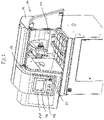
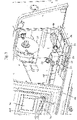
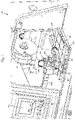
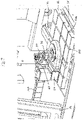
- FIG. 1 shows a cutting machine, more precisely a wet cutting machine of the type Brillant 275 of the applicant, which can be retrofitted with the present invention, as shown in FIG Figures 2 to 5 is evident.
- the cutting machine 10 has a device housing 12 which defines a working space 14 which can be opened and closed by means of a sliding closure hood 16 in order to gain access to the working space 14 .
- a cutting disk 22, in this example a corundum cutting disk 22, is arranged in the working space 14 and is driven by a drive motor which is located in the device housing 12 (not visible in the illustration).
- Coolant nozzles 24 ensure that the cutting disk 22 and the workpiece are cooled accordingly when the separating cuts are made.
- the cutting disk 22 is lowered in the direction of the y-axis by a lifting mechanism 26, in the present example designed as a pivoting mechanism, in order to be placed against the workpiece and to carry out the desired separating cuts.
- a workbench 32 is arranged in the working space 14 and is mounted so that it can be displaced two-dimensionally in the xz plane by means of an xz displacement device 34 , 36 .
- the control of the mechanical displacement of the Work table 32 in the x-direction and in the z-direction as well as the infeed of the cutting wheel 22 in the y-direction is controlled automatically by a program control 42, whereby the starting positions for individual separating cuts can also be controlled manually using a joystick 44. With the joystick 44, the workbench 32 can be manually shifted in the x and z directions. Numerical values can be entered via a touch screen display 46, for example the desired cutting paths or cutting depths.
- the current diameter of the cutting disk 22 can be measured by means of a laser measuring device 48, automatically or by user request, in order to automatically calculate the progressive wear of the cutting disk 22 in the previously programmed separating cuts and thus the wear of the cutting disk 22 between the individual separating cuts during a running To be able to automatically compensate for the separation task.
- a workpiece positioning device 50 is clamped on the workbench 32 and carries a quick-change plate 60, in which in turn the clamping device 70 for the workpiece 80 to be machined is fixed by means of a quick-release catch.
- Workpiece positioning device 50 includes a first mechanical rotary device 52, which rotates workpiece positioning device 50 about a vertical first axis of rotation D, symbolized by arrow 54.
- Workpiece positioning device 50 also includes a second mechanical rotary device 56, which rotates clamping device 70 about a horizontal second Axis of rotation E, which is perpendicular to the first axis of rotation D, is rotated, symbolized by the arrow 58.
- the workpiece 80 ( figure 5 ) by means of the work table 32 in both directions x and z of the work table plane xz by shifting the work table 32 and also rotate it about the two axes D and E by means of the workpiece positioning device 50, which means a wide range of positioning options for the workpiece 80.
- the corresponding separating cuts can be carried out automatically even in the case of complex separating tasks with a plurality of separating cuts at different angles and in different directions, without manual user intervention being necessary, in particular without the workpiece 80 having to be re-clamped.
- FIG. 6 shows a test specimen as an example workpiece in the form of a cam sleeve of an internal combustion engine, on which a total of 12 separating cuts a) to l) are to be carried out as a complex separating task, for example in order to carry out structural tests at different points of the cam sleeve.
- the cam sleeve 80 is clamped into the clamping device 70 in the region of the section 82, as is shown, for example, in figure 5 and 7 is shown.
- the workpiece positioning device 50 has a lower rotating device 52 .
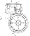
- a 2-phase stepper motor 102 drives a worm 106 via a motor shaft 104, which in turn drives a worm wheel 108.
- the worm wheel 108 runs around a ring gear 110 .
- a top plate 114 is tightly clamped with clamping elements 116 in grooves 118 of the work table, as a result of which the workpiece positioning device 50 is firmly clamped on the work table 32 .
- the engagement of the worm wheel 108 in the ring gear 110 driven by the stepping motor 102, causes the entire workpiece positioning device 50 to rotate with its rotary housing 51 about the head plate 114 or about the axis of rotation D.
- the second rotary device 56 ( Figures 11 to 14 ) rigidly connected to the first rotary device 52.
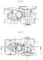
- the second rotary device 56 includes a 2-phase stepping motor 132 which drives a pinion 136 via a motor shaft 134 .
- the pinion 136 drives the worm shaft 142 via an intermediate gear 138 and a pinion 140 .
- the worm 144 seated on the worm shaft 142 drives the worm wheel 146, which is connected to the drive plate 148 and rotates it about the axis of rotation E.
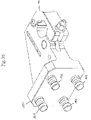
- a quick-release plate 60 with a quick-locking receptacle 152 is attached to the drive plate 148 .
- the clamping device 70 has a connecting plate 154 with quick-action clamping pins 156, which can be latched in the quick-locking receptacle 152 and can be easily released again. As a result, different workpieces with associated clamping devices 70 can be used and exchanged in a simple and rapid manner will.
- the control of the first and second mechanical rotary devices 52, 56 is integrated into the program control 42 of the cutting machine 10.
- the control panel 161 of the cutting machine 10 also has two rotary knobs 162, 164, with which the first and second manual rotary devices 52, 56 can be controlled manually.
- a complex separation task such as that of the cam sleeve 80 in 6 be programmed in that each starting position of the individual separating cuts to be carried out is manually approached by means of the manual operating elements 44, 162, 164.
- the program control 42 then automatically saves the manually approached positions as respective starting positions for each separating cut to be carried out.
- the depth of the separating cuts can then be programmed via the touchscreen display 46.
- the hood 16 is then closed and the entire separating task, including carrying out the 12 separating cuts a) to l), is carried out fully automatically.
- the program control 42 accordingly includes a multi-position process, which allows several separation steps to be programmed one after the other and carried out automatically, with the programming being able to take place step by step.
- the cutting machine according to the invention can thus be referred to as a 5-axis cutting machine 10 .
- the linear axes x and z denote the two-dimensional displacement of the worktable 32
- the axis y the infeed direction between the cutting wheel 22 and the workpiece 80
- the additional axes D and E the two Axis of rotation about which the workpiece 80 can be rotated in addition to the xz shift.
Landscapes
- Engineering & Computer Science (AREA)
- Business, Economics & Management (AREA)
- Human Resources & Organizations (AREA)
- Strategic Management (AREA)
- Physics & Mathematics (AREA)
- General Physics & Mathematics (AREA)
- Theoretical Computer Science (AREA)
- Economics (AREA)
- Development Economics (AREA)
- Entrepreneurship & Innovation (AREA)
- Mechanical Engineering (AREA)
- Accounting & Taxation (AREA)
- Finance (AREA)
- General Business, Economics & Management (AREA)
- Marketing (AREA)
- Game Theory and Decision Science (AREA)
- Quality & Reliability (AREA)
- Software Systems (AREA)
- Operations Research (AREA)
- Tourism & Hospitality (AREA)
- Data Mining & Analysis (AREA)
- General Engineering & Computer Science (AREA)
- Educational Administration (AREA)
- Evolutionary Computation (AREA)
- Artificial Intelligence (AREA)
- Robotics (AREA)
- Mathematical Physics (AREA)
- Computing Systems (AREA)
- Automation & Control Theory (AREA)
- Condensed Matter Physics & Semiconductors (AREA)
- Mathematical Optimization (AREA)
- Computer Vision & Pattern Recognition (AREA)
- Medical Informatics (AREA)
- Computational Mathematics (AREA)
- Pure & Applied Mathematics (AREA)
- Mathematical Analysis (AREA)
- Manufacturing & Machinery (AREA)
- Computational Linguistics (AREA)
- Health & Medical Sciences (AREA)
- Aviation & Aerospace Engineering (AREA)
Description
- Die Erfindung betrifft eine Trennmaschine mit einer rotierenden Trennscheibe zum Durchführen von Trennschnitten in einem Werkstück.
- Trennmaschinen, zum Beispiel Nasstrennschleifmaschinen werden für vielfältige Trennaufgaben eingesetzt. Beispiele für solche Trennmaschinen sind die Geräte der Serie Brillant, zum Beispiel die Trennmaschine Brillant 275 der Anmelderin.
- Ein beispielhaftes Anwendungsgebiet für solche Trennmaschinen ist das Abtrennen von Probenstücken von zu untersuchenden Prüflingen, zum Beispiel in der Automobilindustrie. Hiermit können selektiv an verschiedenen Stellen eines Prüflings zum Beispiel Gefügestrukturen untersucht werden. Hierzu werden mit der Trennmaschine Probestücke aus dem Prüfling herausgeschnitten. Mit dem Nasstrennverfahren ist es möglich, die Probenstücke so zu entnehmen, dass Gefügeschäden durch den Trennschnitt an der späteren Prüffläche gering gehalten werden.
- In vielen Fällen reichen ein oder zwei Trennschnitte um ein Probenstück vom Prüfling zu lösen. Für diese Fälle werden standardisierte Spannwerkzeuge verwendet, um den Prüfling in der Trennmaschine zu fixieren und dann den Trennschnitt zu platzieren und auszuführen. Durch immer größer werdende Anforderungen an Bauteile, zum Beispiel in der Automobilindustrie hinsichtlich ihrer kompakten Bauweise, ihres Gewichts, ihrer Materialeigenschaften, ihres Herstellungsverfahren etc. bei gleichzeitig erhöhten Anforderungen an die Qualität und Zuverlässigkeit der Bauteile werden allerdings auch die Prüfvorgaben aufwendiger und umfangreicher. Dadurch können zum Beispiel Trennaufgaben entstehen, bei welchen, je nach Bauteil, eine Mehrzahl, zum Beispiel 5 bis 10 Probenstücke aus einem Prüfling entnommen werden sollen, was entsprechend viele Trennschnitte ggf. in unterschiedlichen Winkellagen erfordert.
- Nachteilig bei den bisher bekannten Trennmaschinen ist, dass solch komplexe Trennaufgaben manuelle Benutzereingriffe erfordern können, insbesondere kann es erforderlich sein, den Prüfling bzw. das Werkstück ggf. sogar mehrfach umzuspannen, was umständlich und zeitintensiv ist. Hier setzt die vorliegende Erfindung an.
- Die
WO2014/128553A1 betrifft einen Cutter z.B. zum Zuschneiden von Dachsparren.DieWO2014/128553A1 offenbart eine Trennmaschine zum Bearbeiten von Werkstücken mit einer rotierenden Trennscheibe, umfassend eine Trennscheibe und einen Antriebsmotor zum Antreiben der Trennscheibe, eine erste Verschiebeeinrichtung zur Erzeugung einer Relativverschiebung zwischen dem Werkstück und der Trennscheibe in einer ersten Richtung in der x-z-Ebene, um das Werkstück für Trennschnitte mit der Trennscheibe in der ersten Richtung in der x-z-Ebene relativ zu der Trennscheibe zu positionieren, eine Werkstück-Positioniereinrichtung mit einer Einspannvorrichtung zum Einspannen des Werkstücks sowie eine Hubmechanik zum Anstellen der Trennscheibe an das Werkstück in y-Richtung quer zu der x-z-Ebene, um mit der Trennscheibe die Trennschnitte in dem Werkstück durchzuführen. - Die
DE 32 17 705 A1 betrifft eine mit Trenn- oder Schleifscheiben arbeitende Schleifvorrichtung mit einem handbedienten Antriebshebel für den Vorschub des Werkstücks. - Die
US 5,645,466 A betrifft einen Schleifapparat mit einem Schleifrad zum Konturschleifen z.B. von Gasturbinenschaufeln, um Schweißgrate zu entfernen. - Die
EP 1 201 347 A2 betrifft ein kombiniertes Schneid- und (Reib-)Schweißgerät. - Die Erfindung hat sich die Aufgabe gestellt, eine Trennmaschine bereit zu stellen, mit welcher komplexe Trennaufgaben mit wenig manuellem Aufwand für den Benutzer durchführbar sind.
- Eine weitere Aufgabe der Erfindung ist es, eine Trennmaschine bereit zu stellen, mit welcher Trennschnitte in unterschiedlichen Winkellagen schnell und einfach durchzuführen sind.
- Die Aufgabe der Erfindung wird durch den Gegenstand des Anspruch 1 gelöst. Vorteilhafte Weiterbildungen der Erfindung sind in den Unteransprüchen definiert.
- Erfindungsgemäß wird eine Trennmaschine zum Bearbeiten von Werkstücken bereit gestellt, welche eine Trennscheibe zum Durchführen von Trennschnitten in einem Werkstück, z.B. einem Prüfling, und einen Antriebsmotor zum Antreiben der Trennscheibe umfasst.
- Die Trennmaschine umfasst einen Werktisch zum Befestigen des zu bearbeitenden Werkstücks, wobei der Werktisch eine x-z-Ebene, z.B. die horizontale Ebene, definiert.
- Mittels einer ersten Verschiebeeinrichtung kann eine Relativverschiebung zwischen dem Werkstück und der Trennscheibe in einer ersten Richtung in der x-z-Ebene vorgenommen werden, um das Werkstück für Trennschnitte mit der Trennscheibe in der ersten Richtung in der x-z-Ebene relativ zu der Trennscheibe zu positionieren. Die Verschiebung kann je nach Trennmaschine z.B. durch eine Linearverschiebung des Werktisches oder durch eine Linearverschiebung der Trennscheibe erfolgen.
- Die Trennmaschine umfasst ferner eine Werkstück-Positioniereinrichtung mit einer Einspannvorrichtung zum Einspannen des Werkstücks. Die Werkstück-Positioniereinrichtung umfasst eine erste maschinelle Dreheinrichtung mittels welcher das in die Einspannvorrichtung eingespannte Werkstück vor oder zwischen dem Durchführen von Trennschnitten um eine erste Drehachse D gedreht bzw. drehend positioniert werden kann.
- Nach dem linearen und dem drehenden Positionieren des Werkstücks relativ zur Trennscheibe wird die Trennscheibe mittels einer Hubmechanik in y-Richtung quer zu der x-z-Ebene an das Werkstück angestellt, um mit der Trennscheibe Trennschnitte in dem Werkstück durchzuführen. Ein Trennschnitt in dem Werkstück wird ausgeführt, indem die rotierende Trennscheibe, insbesondere in einer Bewegungsrichtung senkrecht zur Rotationsachse der Trennscheibe, in das Werkstück hineingeführt wird und dabei ein Schleif-/Trennvorgang an dem Werkstück stattfindet. Ein Trennschnitt mit einer Trennscheibe erfolgt insbesondere durch einen schleifenden oder abrasiven Abtrag des Materials des Werkstücks. Daher werden Trennmaschinen manchmal auch als Trennschleifmaschinen bezeichnet. Vorzugsweise wird die Trennscheibe auf das Werkstück abgesenkt, z.B. durch eine Schwenkbewegung, es ist allerdings auch möglich die Kinematik umzukehren und den Werktisch quer zur x-z-Ebene auf die Trennscheibe zu zu bewegen, um die Trennscheibe an das Werkstück anzustellen. Vorzugsweise erfolgt die Bewegung der rotierenden Trennscheibe beim Zustellen und Trennen in der Ebene senkrecht zur Rotationsachse der Trennscheibe. Vorzugsweise ist die Trennscheibe nicht um eine Achse senkrecht zur Rotationsachse der Trennscheibe drehbar. Ferner vorzugsweise erfolgt die Zustellung der Trennscheibe bzw. erfolgen die Trennschnitte, insbesondere ausschließlich, unter Bewegung der Hubmechanik in y-Richtung bei ansonsten in der x-z-Ebene feststehendem Werktisch.
- In vorteilhafter Weise kann somit das Werkstück zum Durchführen von Trennschnitten nicht nur linear relativ zu der Trennscheibe positioniert werden, sondern auch gedreht werden, was die Ausführung komplexer Trennaufgaben mit Trennschnitten unter verschiedenen Winkeln ermöglicht. Das Anfahren unterschiedlicher Trennschnitte kann automatisch und ggf. ohne Umspannen des Werkstücks erfolgen. Ferner vorteilhaft kann der Aufwand für komplexe Werkstückentnahmeanweisungen reduziert oder vermieden werden. Hierdurch kann eine Zeitersparnis und eine Reduzierung der manuellen Eingriffe erzielt werden. Mit weiterem Vorteil kann die Anzahl der Einspannwerkzeuge verringert werden und trotzdem können präzise positionierte Trennschnitte durchgeführt werden. Ferner kann die Fehlergefahr minimiert werden.
- Vorzugsweise umfasst die Werkstück-Positioniereinrichtung noch eine zweite maschinelle Dreheinrichtung zum drehenden Positionieren des in die Einspannvorrichtung eingespannten Werkstücks um eine zweite Drehachse E vor oder zwischen dem Durchführen von Trennschnitten. Die zweite Drehachse verläuft vorzugsweise quer, insbesondere senkrecht zu der ersten Drehachse D.
- Hierdurch können die Flexibilität der Positionierung und der Automatisierungsgrad weiter erhöht, die Bearbeitungszeit weiter verkürzt, sowie die Anzahl manuellen Eingriffe und die Anzahl der Einspannwerkzeuge weiter reduziert werden.
- Erfindungsgemäß verläuft die erste Drehachse D senkrecht zur x-z-Ebene des Werktisches.
- Vorzugsweise erlaubt die erste und/oder zweite maschinelle Dreheinrichtung eine Drehung des Werkstücks jeweils um mindestens 90°, besonders bevorzugt um mindestens 180° um die erste bzw. zweite Drehachse. Es hat sich gezeigt, dass eine Drehbarkeit um jeweils 180° plus jeweils 10° Überlauf in beiden Drehrichtungen für die meisten Trennaufgaben ausreichend ist.
- Vorzugsweise umfasst die Trennmaschine eine zweite Verschiebeeinrichtung zur Erzeugung einer Relativverschiebung zwischen dem Werkstück und der Trennscheibe in einer zweiten Richtung in der x-z-Ebene quer, insbesondere senkrecht zur der ersten Richtung, um das Werkstück für Trennschnitte mit der Trennscheibe in der ersten und zweiten Richtung, d.h. in beiden Richtungen in der x-z-Ebene relativ zu der Trennscheibe positionieren zu können. Hierzu kann der Werktisch z.B. eine zweidimensionale x-z-Verschiebemechanik umfassen oder der Werktisch ist in einer Richtung x oder z verschiebbar ausgestaltet und die Trennscheibe lässt sich in der zweiten Richtung senkrecht hierzu verschieben, um die zweidimensionale lineare Relativ-Positionierung in der x-z-Ebene zwischen der Trennscheibe und dem Werkstück zu bewerkstelligen.
- Insbesondere wenn eine zweidimensionale Verschiebbarkeit in der x-z-Ebene und eine Drehbarkeit um beide Achsen D und E gegeben ist, lässt sich das Werkstück automatisch in fast allen Linearpositionen und Drehstellungen relativ zu der Trennscheibe positionieren, so dass ohne Benutzereingriff und ohne Umspannen fast jeder beliebige Trennschnitt in dem Werkstück durchgeführt werden kann. Dies ist mit einer Ersparnis an manueller Arbeitszeit und Bearbeitungsdauer verbunden. In diesem Fall kann von einer 5-Achsen-Trennmaschine gesprochen werden, wobei zwei Achsen von der x-z-Verschiebung, zwei Achsen durch die beiden Drehachsen D und E und die fünfte Achse von der Zustellrichtung y gebildet werden.
- Vorzugsweise erfolgt die Zustellung der Trennscheibe bzw. erfolgen die Trennschnitte unter Bewegung der Hubmechanik in y-Richtung, wobei das Werkstück während dem Durchführen der Trennschnitte nicht um die erste und/oder zweite Drehachse gedreht wird. Mit anderen Worten erfolgt vorzugsweise die Positionierung des Werkstückes in der x-Richtung, in der y-Richtung, um die erste Drehachse und/oder um die zweite Drehachse relativ zu der Trennscheibe lediglich zum Positionieren des Werkstücks vor der Durchführung des Trennschnittes und nicht während der Durchführung des Trennschnittes. Die Durchführung des Trennschnittes erfolgt vorzugsweise ausschließlich durch die Betätigung der Hubmechanik zum Zustellen der rotierenden Trennscheibe an das und hinein in das Werkstück.
- Gemäß einer bevorzugten Ausführungsform der Erfindung ist die Werkstück-Positioniereinrichtung lösbar auf dem Werktisch festspannbar, z.B. in den typischerweise im Werktisch vorhandenen Spann- oder Montagenuten. Die hat den Vorteil, dass bereits vorhandene Trennmaschinen mit der Werkstück-Positioniereinrichtung nachgerüstet werden können und die Werkstück-Positioniereinrichtung z.B. für Wartungs- oder Reinigungsarbeiten abmontiert werden kann. Ferner kann die Werkstück-Positioniereinrichtung z.B. in den Spann- oder Montagenuten auch an unterschiedlichen Stellen festgespannt werden. Trotzdem kann das Werkstück an der Werkstück-Positioniereinrichtung stabil und vibrationsarm festgespannt sein.
- Insbesondere ragt das Werkstück aus der Ebene, die durch den Werktisch definiert wird, hinaus und befindet sich demnach im eingespannten Zustand in einem Raumbereich zwischen dem Werktisch und der Trennscheibe bevor diese an das Werkstück angestellt wird.
- Vorzugsweise umfasst die Werkstück-Positioniereinrichtung jeweils einen Schrittmotor und einen von dem Schrittmotor angetriebenen Schneckenantrieb zum drehenden Positionieren des in die Einspannvorrichtung eingespannten Werkstücks um die erste und/oder zweite Drehachse. Bevorzugt ist die erste und/oder zweite maschinellen Dreheinrichtung somit selbsthemmend ausgebildet. Dadurch kann eine stabile Halterung des Werkstücks gewährleistet werden.
- Gemäß einer bevorzugten Ausführungsform der Erfindung umfasst die Werkstück-Positioniereinrichtung eine Fixierplatte und ein Drehgehäuse. Die Fixierplatte der Werkstück-Positioniereinrichtung wird lösbar auf dem Werktisch festgespannt, z.B. mittels Spannschrauben in den Spann- oder Montagenuten des Werktisches. Das Drehgehäuse ist drehbar um die Fixierplatte gelagert und das Drehgehäuse wird zum drehenden Positionieren des Werkstücks um die erste Drehachse D, insbesondere mitsamt dem ersten und/oder zweiten Antriebsmotor für die erste und zweite maschinelle Dreheinrichtung, um die Fixierplatte gedreht.
- Mit anderen Worten wird zur Drehung um die erste Drehachse D nahezu die gesamte Werkstück-Positioniereinrichtung - bis auf die festgespannte Fixierplatte - gedreht. Dies erlaubt eine stabile Konstruktion und präzise Drehung der Werkstück-Positioniereinrichtung.
- Vorzugsweise weist die Werkstück-Positioniereinrichtung elektrische Zuleitungen auf, welche flexibel um die y-Richtung quer zur x-z-Ebene geführt sind, z.B. mit einer biegsamen Kabelkette, manchmal auch Energiekette genannt.
- Bevorzugt umfasst die Werkstück-Positioniereinrichtung eine Schnellwechselvorrichtung, in welcher die Einspannvorrichtung verrastbar ist, so dass verschiedene Einspannvorrichtungen an der Werkstück-Positioniereinrichtung festlegbar, aber auch schnell und einfach austauschbar sind.
- Die Trennmaschine umfasst ferner ein Gerätegehäuse, welches die Trennscheibe, den Werktisch, die Werkstück-Positioniereinrichtung und/oder die flexibel geführten Zuleitungen beherbergt und einen verschließbaren Arbeitsraum definiert. Das Gerätegehäuse weist hierzu eine Verschlusshaube auf, welche den Arbeitsraum während der Durchführung der Trennschnitte verschließt jedoch vor und nach dem Durchführen der Trennschnitte Zugriff durch den Benutzer auf die Werkstück-Positioniereinrichtung und das Werkstück ermöglicht. In vorteilhafter Weise erfüllt die Trennmaschine somit hohe Sicherheitsanforderungen und ermöglicht das Arbeiten mit hohem Kühlmitteldruck, so dass eine hinreichende Kühlung der Trennscheibe und des Werkstücks gewährleistet sind.
- Die Trennmaschine umfasst ferner eine Programmsteuerung zur automatischen Steuerung der Trennschnitte. Dabei ist die Steuerung der Werkstück-Positioniereinrichtung bzw. die Steuerung der ersten und/oder zweiten Dreheinrichtung in die vorhandene Programmsteuerung der Trennmaschine integriert, so dass die Programmsteuerung die Relativverschiebung in der ersten und/oder der zweiten Richtung und die Drehung des Werkstücks um die erste und/oder zweite Drehachse vor und zwischen Trennschnitten automatisch steuert, so dass mehrere Trennschnitte an unterschiedlichen Positionen in der x-z-Ebene und mit unterschiedlichen Drehstellungen des Werkstücks nacheinander automatisch von der Programmsteuerung angesteuert werden können.
- Ferner vorzugsweise weist die Trennmaschine ein Bedienpanel mit einem oder mehreren Handknöpfen, z.B. Drehknöpfen und/oder sog. Joysticks zum manuellen Ansteuern der ersten und/oder der zweiten Verschiebeeinrichtung und der ersten und/oder zweiten maschinellen Dreheinrichtung auf, um Startpositionen für gewünschte Trennschnitte manuell anfahren zu können.
- Insbesondere können zum Programmieren der gewünschten Trennschnitte die Startposition in der ersten und/oder zweiten Richtung in der x-z-Ebene und bezüglich der ersten und/oder zweiten Drehstellung des Werkstücks für den jeweiligen Trennschnitt manuell mit dem oder den Handknöpfen angefahren und in der Programmsteuerung gespeichert werden. Der zugehörige Trennweg und ggf. weitere Trennparameter wie z.B. Vorschubgeschwindigkeit und/oder stoßweiser Vorschub können z.B. als Zahlenwerte oder Check-Boxen über das Bedienpanel in die Programmsteuerung einprogrammiert werden.
- Vorzugsweise umfasst die Trennmaschine noch eine Durchmesservermessungseinrichtung für die Trennscheibe, welche den Durchmesser der Trennscheibe automatisch, z.B. vor jedem Trennschnitt innerhalb einer Trennaufgabe mit mehreren Trennschnitten oder auf Benutzeranforderung zwischen den Trennschnitten vermisst. Die Programmsteuerung kann dann die vorher bereits gespeicherten Anfahrts- und Trennwege für die nach jeder Vermessung noch durchzuführenden Trennschnitte von der Programmsteuerung automatisch online an die gemessenen Durchmesserwerte anpassen, um die laufende Abnutzung der Trennscheibe auch innerhalb einer Trennaufgabe mit mehreren einzelnen Trennschnitten zu kompensieren.
- Im Folgenden wird die Erfindung anhand von Ausführungsbeispielen und unter Bezugnahme auf die Figuren näher erläutert, wobei gleiche und ähnliche Elemente teilweise mit gleichen Bezugszeichen versehen sind und Merkmale verschiedener Ausführungsbeispiele miteinander kombiniert werden können.
- Es zeigen:
- Fig. 1
- eine perspektivische Darstellung einer Trennmaschine Brillant 275 der Anmelderin,
- Fig. 2
- eine ausschnittsweise perspektivische Darstellung einer Trennmaschine gemäß einem Ausführungsbeispiel der vorliegenden Erfindung,
- Fig. 3
- wie
Fig. 2 mit einer um die vertikale Achse D gedrehten Werkstück-Positioniereinrichtung, - Fig. 4
- die Trennmaschine aus
Fig. 3 in einer Frontalansicht, - Fig. 5
- wie
Fig. 2 mit eingespanntem Werkstück, - Fig. 6
- eine perspektivische Darstellung eines beispielhaften Werkstücks mit zwölf eingezeichneten durchzuführenden Trennschnitten als komplexe Trennaufgabe,
- Fig. 7
- eine perspektivische Darstellung der Werkstück-Positioniereinrichtung montiert auf dem Werktisch der Trennmaschine,
- Fig. 8
- eine teilweise transparente Draufsicht auf die erste maschinelle Dreheinrichtung der Werkstück-Positioniereinrichtung,
- Fig. 9
- ein vertikalen Querschnitt entlang der Linie 9-9 in
Fig. 8 , - Fig. 10
- einen Querschnitt entlang der Linie 10-10 in
Fig. 9 , - Fig. 11
- eine teilweise transparente Ansicht von unten auf die zweite maschinelle Dreheinrichtung der Werkstück-Positioniereinrichtung,
- Fig. 12
- eine teilweise transparente Ansicht von oben auf die zweite maschinelle Dreheinrichtung aus
Fig. 11 , - Fig. 13
- einen vertikalen Querschnitt entlang der Linie 13-13 in
Fig. 12 , - Fig. 14
- einen Querschnitt entlang der Linie 14-14 in
Fig. 13 , - Fig. 15
- eine perspektivische Darstellung der Werkstück-Positioniereinrichtung,
- Fig. 16
- eine perspektivische Darstellung einer Einspannvorrichtung für ein zylindrisches Werkstück mit Anschlussbolzen für eine Schnellwechselvorrichtung,
- Fig. 17
- eine teilweise geschnittene Ansicht der Einspannvorrichtung aus
Fig. 16 . -
Fig. 1 zeigt eine Trennmaschine, genauer eine Nasstrennschleifmaschine von Typ Brillant 275 der Anmelderin, welche mit der vorliegenden Erfindung nachgerüstet werden kann, wie anhand derFig. 2 bis 5 ersichtlich ist. - Bezug nehmend auf die
Fig. 1 bis 5 weist die Trennmaschine 10 ein Gerätegehäuse 12 auf, welches einen Arbeitsraum 14 definiert, welcher mittels einer verschiebbaren Verschlusshaube 16 geöffnet und verschlossen werden kann, um Zugriff auf den Arbeitsraum 14 zu erhalten. In dem Arbeitsraum 14 ist eine Trennscheibe 22, in diesem Beispiel eine Korund-Trennscheibe 22 angeordnet, welche von einem Antriebsmotor angetrieben wird, der sich in dem Gerätegehäuse 12 befindet (in der Darstellung nicht sichtbar). Kühlmitteldüsen 24 sorgen beim Durchführen der Trennschnitte für eine entsprechende Kühlung der Trennscheibe 22 sowie des Werkstücks. Die Trennscheibe 22 wird durch eine Hubmechanik 26, im vorliegenden Beispiel ausgebildet als Schwenkmechanik, in Richtung der y-Achse abgesenkt, um an das Werkstück angestellt zu werden und die gewünschten Trennschnitte durchzuführen. - Im Arbeitsraum 14 ist ein Werktisch 32 angeordnet, welcher mittels einer x-z-Verschiebereinrichtung 34, 36 zweidimensional in der x-z-Ebene verschiebbar gelagert ist. Die Ansteuerung der maschinellen Verschiebung des Werktisches 32 in der x-Richtung und in der z-Richtung sowie das Zustellen der Trennscheibe 22 in y-Richtung wird durch eine Programmsteuerung 42 automatisch gesteuert, wobei die Ansteuerung von Startpositionen für einzelne Trennschnitte auch manuell mittels eines Joysticks 44 durchgeführt werden kann. Mit dem Joystick 44 kann der Werktisch 32 manuell in der x- und z-Richtung verschoben werden. Zahlenwerte können über ein Touchscreen-Display 46 eingegeben werden, zum Beispiel die gewünschten Schnittwege oder Schnitttiefen.
- Vor jedem Trennschnitt kann mittels einer Lasermessvorrichtung 48, automatisch oder per Benutzeranforderung der aktuelle Durchmesser der Trennscheibe 22 vermessen werden, um die fortschreitende Abnutzung der Trennscheibe 22 automatisch in die zuvor programmierten Trennschnitte einzuberechnen und so die Abnutzung der Trennscheibe 22 zwischen den einzelnen Trennschnitten während einer laufenden Trennaufgabe automatisch kompensieren zu können.
- Auf dem Werktisch 32 ist eine Werkstück-Positioniereinrichtung 50 festgespannt, welche eine Schnellwechselplatte 60 trägt, in welcher wiederum die Einspannvorrichtung 70 für das zu bearbeitende Werkstück 80 mittels Schnellspannverrastung festgelegt ist. Die Werkstück-Positioniereinrichtung 50 umfasst eine erste maschinelle Dreheinrichtung 52 welche die Werkstück-Positioniereinrichtung 50 um eine vertikale erste Drehachse D dreht, symbolisiert durch den Pfeil 54. Ferner umfasst die Werkstück-Positioniereinrichtung 50 eine zweite maschinelle Dreheinrichtung 56 welche die Einspannvorrichtung 70 um eine horizontale zweite Drehachse E, welche zur ersten Drehachse D senkrecht steht rotiert, symbolisiert durch den Pfeil 58.
- Somit lässt sich das in die Einspannvorrichtung 70 eingespannte Werkstück 80 (
Fig. 5 ) mittels des Werktisches 32 in beiden Richtungen x und z der Werktischebene x-z durch Verschiebung des Werktisches 32 verschieben und zusätzlich mittels der Werkstück-Positioniereinrichtung 50 um die beiden Achsen D und E drehen, was eine vielfältige Positioniermöglichkeit für das Werkstück 80 bedeutet. Dadurch können selbst bei komplexen Trennaufgaben mit mehreren Trennschnitten unter verschiedenen Winkeln und in verschiedenen Richtungen die entsprechenden Trennschnitte automatisch durchgeführt werden, ohne dass ein manueller Benutzereingriff, insbesondere ohne dass ein Umspannen des Werkstücks 80, notwendig ist. -
Fig. 6 zeigt einen Prüfling als beispielhaftes Werkstück in Form einer Nockenhülse eines Verbrennungsmotors, an welcher als komplexe Trennaufgabe insgesamt 12 Trennschnitte a) bis l) durchgeführt werden sollen, zum Beispiel um Gefügeuntersuchungen an verschiedenen Stellen der Nockenhülse durchzuführen. Mit der erfindungsgemäßen Trennmaschine 10 ist es möglich, alle 12 Trennschnitte a) bis l) vollautomatisiert und ohne Umspannen des Werkstücks 80 vorzunehmen. Die Nockenhülse 80 wird dabei in Bereich des Abschnitts 82 in die Einspannvorrichtung 70 eingespannt, wie dies zum Beispiel inFig. 5 und7 dargestellt ist. - Bezug nehmend auf die
Fig. 8 bis 10 weist die Werkstück-Positioniereinrichtung 50 eine untere Dreheinrichtung 52 auf. Ein 2-Phasen-Schrittmotor 102 treibt über eine Motorwelle 104 eine Schnecke 106 an, welche wiederum ein Schneckenrad 108 antreibt. Das Schneckenrad 108 läuft um einen Zahnkranz 110 um. Eine Kopfplatte 114 ist mit Spannelementen 116 in Nuten 118 des Werktisches fest verspannt, wodurch die Werkstück-Positioniereinrichtung 50 fest auf dem Werktisch 32 verspannt ist. Durch den Eingriff des Schneckenrades 108 in den Zahnkranz 110 dreht sich, angetrieben durch den Schrittmotor 102, die gesamte Werkstück-Positioniereinrichtung 50 mit ihrem Drehgehäuse 51 um die Kopfplatte 114, bzw. um die Drehachse D herum. - Mit einer Schwalbenschwanzführung 120, 121 ist die zweite Dreheinrichtung 56 (
Fig. 11 bis 14 ) starr mit der ersten Dreheinrichtung 52 verbunden. - Bezug nehmend auf die
Fig. 11 bis 14 umfasst die zweite Dreheinrichtung 56 einen 2-Phasen Schrittmotor 132, welcher über eine Motorwelle 134 ein Ritzel 136 antreibt. Das Ritzel 136 treibt über ein Zwischenzahnrad 138 und ein Ritzel 140 die Schneckenwelle 142 an. Die auf der Schneckenwelle 142 sitzende Schnecke 144 treibt das Schneckenrad 146 an, welches mit der Antriebsplatte 148 verbunden ist und diese um die Drehachse E dreht. - Bezug nehmend auf die
Fig. 15 bis 17 ist an der Antriebsplatte 148 eine Schnellwechselplatte 60 mit einer Schnellrastaufnahme 152 befestigt. Die Einspannvorrichtung 70 besitzt eine Anschlussplatte 154 mit Schnellspannzapfen 156, welche in der Schnellrastaufnahme 152 verrastbar und leicht wieder lösbar sind. Hierdurch können verschiedene Werkstücke mit zugehörigen Einspannvorrichtungen 70 in einfacher und schneller Weise eingesetzt und ausgewechselt werden. - Die Steuerung der ersten und zweiten maschinellen Dreheinrichtungen 52, 56 ist in die Programmsteuerung 42 der Trennmaschine 10 integriert. Das Bedienpanel 161 der Trennmaschine 10 weist neben dem Joystick 44 für die x-z-Ansteuerung des Werktisches 32 noch zwei Drehknöpfe 162, 164 auf, mit welchen die erste und zweite manuelle Dreheinrichtung 52, 56 manuell gesteuert werden können. So kann zum Beispiel eine komplexe Trennaufgabe wie diejenige der Nockenhülse 80 in
Fig. 6 dadurch programmiert werden, dass mittels der manuellen Bedienelemente 44, 162, 164 jede Startposition der einzelnen durchzuführenden Trennschnitte manuell angefahren wird. Die Programmsteuerung 42 speichert dann automatisch die manuell angefahrenen Positionen als jeweilige Startpositionen für jeden durchzuführenden Trennschnitt. Die Tiefe der Trennschnitte kann dann über das Touchscreen-Display 46 einprogrammiert werden. Anschließend wird die Haube 16 geschlossen und die gesamte Trennaufgabe, umfassend die Durchführung der 12 Trennschnitte a) bis l), wird vollautomatisch ausgeführt. Die Programmsteuerung 42 umfasst demnach einen Multi-Positions-Prozess, welcher es erlaubt, mehrere Trennschritte nacheinander zu programmieren und automatisch auszuführen, wobei das Programmieren Schritt für Schritt erfolgen kann. - Die erfindungsgemäße Trennmaschine kann somit als 5-Achsen-Trennmaschine 10 bezeichnet werden. Hierbei bezeichnen die linearen Achsen x und z die zweidimensionale Verschiebung des Werktisches 32, die Achse y die Zustellrichtung zwischen der Trennscheibe 22 und dem Werkstück 80 und die zusätzlichen Achsen D und E die beiden Drehachsen, um welche das Werkstück 80 zusätzlich zur x-z-Verschiebung gedreht werden kann.
- Es ist dem Fachmann ersichtlich, dass die vorstehend beschriebenen Ausführungsformen beispielhaft zu verstehen sind und die Erfindung nicht auf diese beschränkt ist, sondern in vielfältiger Weise variiert werden kann, ohne den Schutzbereich der Ansprüche zu verlassen. Es ist ersichtlich, dass die Merkmale unabhängig davon, ob sie in der Beschreibung, den Ansprüchen, den Figuren oder anderweitig offenbart sind, auch einzeln wesentliche Bestandteile der Erfindung definieren, selbst wenn sie zusammen mit anderen Merkmalen gemeinsam beschrieben sind.
Claims (14)
- Trennmaschine (10) zum Bearbeiten von Werkstücken (80) mit einer rotierenden Trennscheibe (22), umfassendeine Trennscheibe (22) und einen Antriebsmotor zum Antreiben der Trennscheibe (22),einen Werktisch (32) zum Befestigen eines zu bearbeitenden Werkstücks (80), wobei der Werktisch (32) eine x-z-Ebene definiert,eine erste Verschiebeeinrichtung (34) zur Erzeugung einer Relativverschiebung zwischen dem Werkstück (80) und der Trennscheibe (22) in einer ersten Richtung in der x-z-Ebene, um das Werkstück (80) für Trennschnitte (22) mit der Trennscheibe (22) in der ersten Richtung in der x-z-Ebene relativ zu der Trennscheibe (22) zu positionieren,eine Werkstück-Positioniereinrichtung (50) mit einer Einspannvorrichtung (70) zum Einspannen des Werkstücks (80) und einer ersten maschinellen Dreheinrichtung (52) zum drehenden Positionieren des in die Einspannvorrichtung (70) eingespannten Werkstücks (80) um eine erste Drehachse (D) vor oder zwischen dem Durchführen von Trennschnitten, wobei die erste Drehachse (D) senkrecht zur x-z-Ebene verläuft,ein Gerätegehäuse (12), welches die Trennscheibe (22), den Werktisch (32) und die Werkstück-Positioniereinrichtung (50) beherbergt und einen Arbeitsraum (14) definiert, wobei das Gerätegehäuse (12) eine Verschlusshaube (16) aufweist, welche den Arbeitsraum (14) während der Durchführung der Trennschnitte verschließt und vor und nach dem Durchführen der Trennschnitte Zugriff durch den Benutzer auf die Werkstück-Positioniereinrichtung (50) und das Werkstück (80) ermöglicht,eine Hubmechanik (26) zum Anstellen der Trennscheibe (22) an das Werkstück (80) in y-Richtung quer zu der x-z-Ebene, um mit der Trennscheibe (22) die Trennschnitte in dem Werkstück (80) durchzuführen undeine Programmsteuerung (42), in welche die Steuerung der ersten Dreheinrichtung (52) integriert ist, so dass die Programmsteuerung (42) die Relativverschiebung in der ersten Richtung und die Drehung des Werkstücks (80) um die erste Drehachse (D) vor und zwischen Trennschnitten automatisch steuert, so dass mehrere Trennschnitte an unterschiedlichen Positionen in der x-z-Ebene und mit unterschiedlichen Drehstellungen des Werkstücks (80) nacheinander automatisch angesteuert werden.
- Trennmaschine (10) nach Anspruch 1,
wobei die Werkstück-Positioniereinrichtung (50) eine zweite maschinelle Dreheinrichtung (56) zum drehenden Positionieren des in die Einspannvorrichtung (70) eingespannten Werkstücks (80) um eine zweite Drehachse (E) vor oder zwischen dem Durchführen von Trennschnitten umfasst. - Trennmaschine (10) nach Anspruch 1 oder 2,
wobei die zweite Drehachse (E) parallel zur x-z-Ebene verläuft. - Trennmaschine (10) nach einem der vorstehenden Ansprüche,
wobei die erste und/oder zweite maschinelle Dreheinrichtung (52, 56) eine Drehung des Werkstücks jeweils um mindestens 90° um die erste bzw. zweite Drehachse (D, E) erlaubt. - Trennmaschine (10) nach einem der vorstehenden Ansprüche,
ferner umfassend eine zweite Verschiebeeinrichtung (36) zur Erzeugung einer Relativverschiebung zwischen dem Werkstück (80) und der Trennscheibe (22) in einer zweiten Richtung in der x-z-Ebene quer zur der ersten Richtung, um das Werkstück (80) für Trennschnitte mit der Trennscheibe (22) in der ersten und zweiten Richtung in der x-z-Ebene relativ zu der Trennscheibe (22) zu positionieren. - Trennmaschine (10) nach einem der vorstehenden Ansprüche,
wobei die Werkstück-Positioniereinrichtung (50) lösbar auf dem Werktisch (32) festspannbar ist. - Trennmaschine (10) nach einem der vorstehenden Ansprüche,
wobei die Werkstück-Positioniereinrichtung (50) jeweils einen Schrittmotor (102, 132) und einen von dem Schrittmotor (102, 132) angetriebenen Schneckenantrieb (106, 108, 144, 146) zum drehenden Positionieren des in die Einspannvorrichtung (70) eingespannten Werkstücks (80) um die erste und/oder zweite Drehachse (D, E) umfasst. - Trennmaschine (10) nach einem der vorstehenden Ansprüche,
wobei die Werkstück-Positioniereinrichtung (50) eine Fixierplatte (114) und ein Drehgehäuse (51) umfasst, wobei die Fixierplatte (114) lösbar auf dem Werktisch (32) festspannbar ist und das Drehgehäuse (51) um die Fixierplatte (114) drehbar gelagert ist, derart dass zum drehenden Positionieren des Werkstücks (80) um die erste Drehachse (D) das Drehgehäuse (51), insbesondere mitsamt dem ersten und/oder dem zweiten Schrittmotor (102, 132), um die Fixierplatte (114) gedreht wird. - Trennmaschine (10) nach einem der vorstehenden Ansprüche,
wobei die Werkstück-Positioniereinrichtung (50) Zuleitungen (160) aufweist, welche flexibel um die y-Richtung quer zur x-z-Ebene geführt sind. - Trennmaschine (10) nach einem der vorstehenden Ansprüche,
wobei die Werkstück-Positioniereinrichtung (50) eine Schnellwechselvorrichtung (60) umfasst, mittels welcher verschiedene Einspannvorrichtungen (70) an der Werkstück-Positioniereinrichtung (50) festlegbar sind. - Trennmaschine (10) nach einem der Ansprüche 2-10,
wobei die Steuerung der zweiten Dreheinrichtung (56) in die Programmmsteuerung (42) integriert ist, so dass die Programmsteuerung (42) die Relativverschiebung in der ersten und/oder zweiten Richtung und die Drehung des Werkstücks (80) um die zweite Drehachse (E) vor und zwischen Trennschnitten automatisch steuert, so dass mehrere Trennschnitte an unterschiedlichen Positionen in der x-z-Ebene und mit unterschiedlichen Drehstellungen des Werkstücks (80) nacheinander automatisch angesteuert werden. - Trennmaschine (10) nach einem der vorstehenden Ansprüche,
umfassend ein oder mehrere Hand-Bedienelemente (44, 162, 164) zum manuellen Ansteuern der ersten und/oder zweiten Verschiebeeinrichtung (34, 36) und der ersten und/oder zweiten maschinellen Dreheinrichtung (52, 56), um gewünschte Trennschnitte manuell anfahren zu können. - Trennmaschine (10) nach einem der vorstehenden Ansprüche,
wobei zum Programmieren der gewünschten Trennschnitte die Startposition in der ersten und/oder zweiten Richtung in der x-z-Ebene und bezüglich der ersten und/oder der zweiten Drehstellung des Werkstücks (80) für den jeweiligen Trennschnitt manuell mit dem oder den Handbedienelementen (44, 162, 164) angefahren und gespeichert wird und der zugehörige Trennweg und ggf. weitere Trennparameter als Zahlenwerte in die Programmsteuerung (42) einprogrammiert werden. - Trennmaschine (10) nach einem der vorstehenden Ansprüche,
umfassend eine Durchmesservermessungseinrichtung (48) für die Trennscheibe (22), welche den Durchmesser der Trennscheibe (22) automatisch oder auf Benutzeranforderung zwischen den Trennschnitten vermisst und wobei die in der Programmsteuerung (42) gespeicherten Anfahrts- und Trennwege für die nach der Vermessung noch durchzuführenden Trennschnitte von der Programmsteuerung (42) automatisch an die gemessenen Durchmesserwerte angepasst werden.
Priority Applications (1)
| Application Number | Priority Date | Filing Date | Title |
|---|---|---|---|
| EP22186726.0A EP4112227A1 (de) | 2016-02-09 | 2017-02-09 | Trennmaschine |
Applications Claiming Priority (2)
| Application Number | Priority Date | Filing Date | Title |
|---|---|---|---|
| DE102016102218.7A DE102016102218A1 (de) | 2016-02-09 | 2016-02-09 | Trennmaschine |
| PCT/EP2017/052853 WO2017137490A1 (de) | 2016-02-09 | 2017-02-09 | Trennmaschine, werkstückpositioniereinrichtung |
Related Child Applications (1)
| Application Number | Title | Priority Date | Filing Date |
|---|---|---|---|
| EP22186726.0A Division EP4112227A1 (de) | 2016-02-09 | 2017-02-09 | Trennmaschine |
Publications (2)
| Publication Number | Publication Date |
|---|---|
| EP3414050A1 EP3414050A1 (de) | 2018-12-19 |
| EP3414050B1 true EP3414050B1 (de) | 2022-07-27 |
Family
ID=58016703
Family Applications (2)
| Application Number | Title | Priority Date | Filing Date |
|---|---|---|---|
| EP17704453.4A Active EP3414050B1 (de) | 2016-02-09 | 2017-02-09 | Trennmaschine |
| EP22186726.0A Pending EP4112227A1 (de) | 2016-02-09 | 2017-02-09 | Trennmaschine |
Family Applications After (1)
| Application Number | Title | Priority Date | Filing Date |
|---|---|---|---|
| EP22186726.0A Pending EP4112227A1 (de) | 2016-02-09 | 2017-02-09 | Trennmaschine |
Country Status (8)
| Country | Link |
|---|---|
| US (2) | US11660719B2 (de) |
| EP (2) | EP3414050B1 (de) |
| JP (1) | JP6847970B2 (de) |
| CN (1) | CN108602171B (de) |
| DE (2) | DE102016102218A1 (de) |
| DK (1) | DK3414050T3 (de) |
| ES (1) | ES2929015T3 (de) |
| WO (1) | WO2017137490A1 (de) |
Families Citing this family (20)
| Publication number | Priority date | Publication date | Assignee | Title |
|---|---|---|---|---|
| DE102016102218A1 (de) | 2016-02-09 | 2017-08-10 | Atm Gmbh | Trennmaschine |
| CH713798A1 (de) * | 2017-05-19 | 2018-11-30 | Reishauer Ag | Maschine zur Feinbearbeitung von verzahnten Werkstücken sowie Verfahren zur Vermessung von Kenngrössen eines Feinbearbeitungswerkzeugs. |
| CN107175370A (zh) * | 2017-07-14 | 2017-09-19 | 长兴德源机械科技有限公司 | 一种自动化数控切割设备 |
| CN108145491A (zh) * | 2018-02-09 | 2018-06-12 | 苏州经贸职业技术学院 | 夹具 |
| CN108687658B (zh) * | 2018-03-23 | 2022-06-14 | 先德智能装备股份有限公司 | 工件加工设备 |
| US11925465B2 (en) * | 2018-06-01 | 2024-03-12 | ClearTrac Technologies, LLC | Uroflowmeter |
| USD932632S1 (en) | 2018-07-13 | 2021-10-05 | ClearTrac Technologies, LLC | Uroflowmeter |
| US11897084B2 (en) * | 2018-09-07 | 2024-02-13 | Illinois Tool Works Inc. | Compact material removal machines |
| DE202018005258U1 (de) | 2018-11-13 | 2019-01-10 | Hochschule Trier | Scheibenförmiges Werkzeug zur Bearbeitung von Werkstücken, Trennvorrichtung sowie Verwendung einer Trenn-, Schleif- und Polierscheibe zum Erzeugen einer Oberflächenstruktur auf einem Werkstück |
| RS63356B1 (sr) | 2018-11-13 | 2022-07-29 | Klingspor Ag | Disk za sečenje, brušenje i poliranje i postupak za obradu radnih komada |
| CN114474418B (zh) * | 2020-10-23 | 2024-08-23 | 上海东河机电科技有限公司 | 一种斜角布局大工件金刚石砂线切割机 |
| CN112192381A (zh) * | 2020-10-26 | 2021-01-08 | 张仕艳 | 一种具有废料收集的智能加工用表面打磨装置及使用方法 |
| CN114131488A (zh) * | 2021-11-10 | 2022-03-04 | 杭州宏立机械制造有限公司 | 一种拉杆切槽机 |
| CN115609420B (zh) * | 2022-09-09 | 2026-07-17 | 上海富吉医疗科技有限公司 | 穿刺注射针针尖加工设备及方法 |
| CN219093836U (zh) * | 2022-12-13 | 2023-05-30 | 曼弗莱德智能制造(江苏)有限公司 | 一种五轴联动伺服圆盘锯切设备 |
| KR102686871B1 (ko) * | 2023-04-11 | 2024-07-19 | 주식회사 에이텍 | 파이프형 프레임 부재 절삭가공 장치 |
| WO2024259639A1 (en) * | 2023-06-21 | 2024-12-26 | Illinois Tool Works Inc. | Systems and methods for measuring a size of a cutting wheel |
| JP7884490B2 (ja) | 2023-10-13 | 2026-07-03 | 東芝テック株式会社 | 情報処理装置 |
| CN117564850A (zh) * | 2023-12-18 | 2024-02-20 | 安徽博马智能装备有限公司 | 一种铝合金压铸件的柔性去毛刺站 |
| CN117733259B (zh) * | 2024-01-18 | 2025-03-14 | 池州市千润宇信息技术有限公司 | 一种线切割设备 |
Citations (14)
| Publication number | Priority date | Publication date | Assignee | Title |
|---|---|---|---|---|
| DE3217705A1 (de) | 1981-08-24 | 1983-03-03 | Buehler Ltd., 60044 Lake Bluff, Ill. | Mit trenn- oder schleifscheiben arbeitende schneidvorrichtung |
| US4981402A (en) | 1987-08-24 | 1991-01-01 | The Gleason Works | Multi-axis bevel and hypoid gear generating machine |
| US5224716A (en) | 1990-10-09 | 1993-07-06 | Tsubakimoto Chain Co. | Tilting workpiece support having fine adjustment mechanism |
| US5645466A (en) | 1994-06-17 | 1997-07-08 | Wikle; Kenneth C. | Apparatus and method for contour grinding gas turbine blades |
| EP0743889B1 (de) | 1994-02-07 | 1998-01-07 | Struers A/S | Vorrichtung zum schneiden von materialproben von einem probenkörper |
| EP0823310A1 (de) | 1996-02-27 | 1998-02-11 | Kitamura Machinery Co., Ltd. | Werkzeugmaschine für kombinierte arbeit |
| EP1201347A2 (de) | 2000-10-27 | 2002-05-02 | Hitachi, Ltd. | Bearbeitungsmaschine mit kombinierter Bewegung und Reibrührschweissverfahren |
| WO2006012051A2 (en) | 2004-06-25 | 2006-02-02 | Thor Power Corp. | Electrical device for automatically adjusting operating speed of a tool based on tool wear |
| CN201026534Y (zh) | 2007-03-22 | 2008-02-27 | 李见成 | 切割机床 |
| EP2662186A1 (de) | 2011-01-07 | 2013-11-13 | Bando Kiko Co., Ltd | Verfahren und vorrichtung zum gravieren einer siliciumcarbidplatte |
| WO2014128553A1 (en) | 2013-02-25 | 2014-08-28 | Criddle Erron | Cutter |
| JP2014172123A (ja) | 2013-03-08 | 2014-09-22 | Fuji Heavy Ind Ltd | 傘歯車の歯切り加工方法および装置 |
| JP2015170805A (ja) | 2014-03-10 | 2015-09-28 | 株式会社ディスコ | 板状物の加工方法 |
| DE102016102218A1 (de) | 2016-02-09 | 2017-08-10 | Atm Gmbh | Trennmaschine |
Family Cites Families (28)
| Publication number | Priority date | Publication date | Assignee | Title |
|---|---|---|---|---|
| US4115956A (en) * | 1977-06-28 | 1978-09-26 | S. E. Huffman Corporation | Programmably controlled machine for grinding end cutting tools and the like |
| JPS59159529A (ja) | 1983-03-03 | 1984-09-10 | Nec Corp | 拡散炉制御装置 |
| JPH0415011Y2 (de) | 1985-07-08 | 1992-04-03 | ||
| JPS63182856U (de) * | 1987-08-31 | 1988-11-25 | ||
| DE3729162A1 (de) * | 1987-09-01 | 1989-03-09 | Guehring Automation | Werkzeugmaschine zur bearbeitung von werkstuecken mittels rundlaufender werkzeuge |
| US4989372A (en) * | 1988-07-27 | 1991-02-05 | The Boeing Company | Precision radial arm saw for composite materials |
| JPH04100689A (ja) * | 1990-08-14 | 1992-04-02 | Tsubakimoto Chain Co | レーザ加工機用5軸テーブル |
| US5377454A (en) * | 1992-05-01 | 1995-01-03 | The Gleason Works | Method of truing and angling cutter blades by sharpening |
| JP2808985B2 (ja) | 1992-05-25 | 1998-10-08 | 日本電気株式会社 | 情報処理装置及びデバッグ装置 |
| DE4242906C2 (de) * | 1992-12-18 | 1995-09-14 | Walter Ag | Numerisch gesteuerte Schleifmaschine zum Schleifen von vorzugsweise metallischen Werkstücken, insbesondere Werkzeugen |
| DE50211104D1 (de) * | 2001-05-17 | 2007-12-06 | Chiron Werke Gmbh | Werkzeugmaschine und Verfahren zur Bearbeitung eines stangenförmigen Werkstücks |
| US20040089125A1 (en) * | 2002-11-08 | 2004-05-13 | Emerson Electric Co. | Compound miter saw |
| US7000658B1 (en) * | 2004-01-29 | 2006-02-21 | Harry Soukiassian | Precision adjustable woodworking platform |
| EP1595639A1 (de) | 2004-05-11 | 2005-11-16 | Liechti Engineering AG | Werkzeugmaschine zum Bearbeiten von ringförmigen Werkstücken |
| JP2006082158A (ja) * | 2004-09-15 | 2006-03-30 | Okamoto Machine Tool Works Ltd | ワ−クの研削方法および研削装置 |
| US20100260569A1 (en) * | 2009-04-09 | 2010-10-14 | Marnie Elizabeth Jean Ham | Mill bed |
| US20100257711A1 (en) * | 2009-04-10 | 2010-10-14 | Ferguson Patrick J | Machine tool and methods for pointing wire |
| JP2011067876A (ja) * | 2009-09-24 | 2011-04-07 | Toshiba Corp | 加工装置 |
| JP5389604B2 (ja) * | 2009-10-20 | 2014-01-15 | 株式会社ディスコ | 切削装置における切削ブレードの消耗量管理方法 |
| CN201848649U (zh) * | 2010-10-26 | 2011-06-01 | 南京南传激光设备有限公司 | 双转台五轴联动三维光纤激光数控切割机 |
| JP5129320B2 (ja) * | 2010-12-15 | 2013-01-30 | 株式会社岡本工作機械製作所 | 円筒状単結晶シリコンインゴットブロックを四角柱状ブロックに加工する切断装置および切断方法 |
| CN202399118U (zh) * | 2011-12-31 | 2012-08-29 | 陕西万方汽车零部件有限公司 | 改进的砂轮锯片切割机 |
| DE102012201736B3 (de) * | 2012-02-06 | 2013-06-27 | Deckel Maho Pfronten Gmbh | Universal-Werkzeugmaschine mit Spänesammelraum |
| US9539698B2 (en) * | 2012-04-16 | 2017-01-10 | Mori Seiki Co., Ltd. | Grind hardening method |
| JP6261967B2 (ja) * | 2013-12-03 | 2018-01-17 | 株式会社ディスコ | 加工装置 |
| CN204035685U (zh) * | 2014-09-15 | 2014-12-24 | 陕西万方汽车零部件有限公司 | 弯管复合斜面切割设备 |
| ITMI20150580A1 (it) * | 2015-04-22 | 2016-10-22 | Gmm S P A | Macchina per la lavorazione di materiali in lastra |
| US9821426B2 (en) * | 2015-06-23 | 2017-11-21 | Cadillaxis, Llc | Apparatus for adding an additional rotation axis to a multi-axis tooling machine |
-
2016
- 2016-02-09 DE DE102016102218.7A patent/DE102016102218A1/de active Pending
- 2016-02-09 DE DE202016102268.1U patent/DE202016102268U1/de not_active Expired - Lifetime
-
2017
- 2017-02-09 EP EP17704453.4A patent/EP3414050B1/de active Active
- 2017-02-09 ES ES17704453T patent/ES2929015T3/es active Active
- 2017-02-09 US US16/076,446 patent/US11660719B2/en active Active
- 2017-02-09 JP JP2018543106A patent/JP6847970B2/ja active Active
- 2017-02-09 DK DK17704453.4T patent/DK3414050T3/da active
- 2017-02-09 WO PCT/EP2017/052853 patent/WO2017137490A1/de not_active Ceased
- 2017-02-09 EP EP22186726.0A patent/EP4112227A1/de active Pending
- 2017-02-09 CN CN201780008727.6A patent/CN108602171B/zh active Active
-
2023
- 2023-04-17 US US18/301,406 patent/US20230249310A1/en active Pending
Patent Citations (17)
| Publication number | Priority date | Publication date | Assignee | Title |
|---|---|---|---|---|
| DE3217705A1 (de) | 1981-08-24 | 1983-03-03 | Buehler Ltd., 60044 Lake Bluff, Ill. | Mit trenn- oder schleifscheiben arbeitende schneidvorrichtung |
| US4424649A (en) | 1981-08-24 | 1984-01-10 | Buehler Ltd. | Abrasive cutter |
| US4981402A (en) | 1987-08-24 | 1991-01-01 | The Gleason Works | Multi-axis bevel and hypoid gear generating machine |
| US5224716A (en) | 1990-10-09 | 1993-07-06 | Tsubakimoto Chain Co. | Tilting workpiece support having fine adjustment mechanism |
| EP0743889B1 (de) | 1994-02-07 | 1998-01-07 | Struers A/S | Vorrichtung zum schneiden von materialproben von einem probenkörper |
| US5645466A (en) | 1994-06-17 | 1997-07-08 | Wikle; Kenneth C. | Apparatus and method for contour grinding gas turbine blades |
| EP0823310A1 (de) | 1996-02-27 | 1998-02-11 | Kitamura Machinery Co., Ltd. | Werkzeugmaschine für kombinierte arbeit |
| EP1201347A2 (de) | 2000-10-27 | 2002-05-02 | Hitachi, Ltd. | Bearbeitungsmaschine mit kombinierter Bewegung und Reibrührschweissverfahren |
| WO2006012051A2 (en) | 2004-06-25 | 2006-02-02 | Thor Power Corp. | Electrical device for automatically adjusting operating speed of a tool based on tool wear |
| CN201026534Y (zh) | 2007-03-22 | 2008-02-27 | 李见成 | 切割机床 |
| EP2662186A1 (de) | 2011-01-07 | 2013-11-13 | Bando Kiko Co., Ltd | Verfahren und vorrichtung zum gravieren einer siliciumcarbidplatte |
| WO2014128553A1 (en) | 2013-02-25 | 2014-08-28 | Criddle Erron | Cutter |
| JP2014172123A (ja) | 2013-03-08 | 2014-09-22 | Fuji Heavy Ind Ltd | 傘歯車の歯切り加工方法および装置 |
| JP2015170805A (ja) | 2014-03-10 | 2015-09-28 | 株式会社ディスコ | 板状物の加工方法 |
| DE102016102218A1 (de) | 2016-02-09 | 2017-08-10 | Atm Gmbh | Trennmaschine |
| WO2017137490A1 (de) | 2016-02-09 | 2017-08-17 | Atm Gmbh | Trennmaschine, werkstückpositioniereinrichtung |
| EP4112227A1 (de) | 2016-02-09 | 2023-01-04 | ATM Qness GmbH | Trennmaschine |
Non-Patent Citations (32)
| Title |
|---|
| "ATM Brillant 220", 6 February 2013 (2013-02-06), Retrieved from the Internet <URL:https://www.youtube.com/watch?v=kXHtCCzQUrQ> |
| "Brillant 275 Cut Off Saw", 28 May 2015 (2015-05-28), Retrieved from the Internet <URL:https://www.youtube.com/watch?v=GengiKP15vQ> |
| "Werkzeugmaschinen Fertigungssysteme Band 1 - Maschinenarten, Bauformen und Anwendungsbereiche", 1 January 1991, ISBN: 3-18-401095-3, article WECK, MANFRED: "3.1.5 Spanende Maschinen für Werkzeuge mit geometrischunbestimmten Schneiden ", pages: 210 - 263, XP009555330 |
| "Werkzeugmaschinen Fertigungssysteme Band 1 - Maschinenarten, Bauformen und Anwendungsbereiche", 1 January 1991, VDI VERLAG, Düsseldorf, ISBN: 3-18-401095-3, article WECK, MANFRED: "Chapter 2: Begriffe im Werkzeugmaschinenbau ", pages: 20 - 40, XP009555328 |
| ANONYMOUS: "Axitom-5", STRUERS, 1 September 2012 (2012-09-01), XP093152033, Retrieved from the Internet <URL:https://documents.uow.edu.au/content/groups/public/@web/@aiim/documents/doc/uow155161.pdf> |
| ANONYMOUS: "Bremsscheibe ", WIKIPEDIA, 4 January 2016 (2016-01-04), XP093152206, Retrieved from the Internet <URL:https://de.wikipedia.org/w/index.php?title=Bremsscheibe&oldid=149774876> |
| ANONYMOUS: "Brillant 2000", ATM, 1 October 2014 (2014-10-01), XP093152185 |
| ANONYMOUS: "Brillant 220 Trennmaschine", ATM NEWSLETTER, 27 April 2010 (2010-04-27), XP093152187 |
| ANONYMOUS: "Brillant 265", ATM, 1 April 2012 (2012-04-01), XP093152181 |
| ANONYMOUS: "Brillant 285", ATM, 1 January 2013 (2013-01-01), XP093152131 |
| ANONYMOUS: "Easy-Clamping Base - UIC, Flexible and Coplanar", ATM, 1 October 2014 (2014-10-01), XP093152194 |
| ANONYMOUS: "https://de.wikipedia.org/wiki/Trennscheibe_(Werkzeug)", WIKIPEDIA, 22 August 2014 (2014-08-22), pages 1 - 7, XP093234785, Retrieved from the Internet <URL:https://de.wikipedia.org/wiki/Trennscheibe_(Werkzeug)> |
| ANONYMOUS: "Maschinenbauingenieur ", WIKIPEDIA, 12 February 2022 (2022-02-12), XP093152209, Retrieved from the Internet <URL:https://de.wikipedia.org/w/index.php?title=Maschinenbauingenieur&oldid=220119901> |
| ANONYMOUS: "MFP 50 (V2)", MÄGERLE, 1 April 2014 (2014-04-01), XP093152214 |
| ANONYMOUS: "Numerical control", WIKIPEDIA, 18 July 2022 (2022-07-18), XP093152211, Retrieved from the Internet <URL:https://en.wikipedia.org/w/index.php?title=Numerical%20control&oldid=1098989074> |
| ANONYMOUS: "Rotary table", WIKIPEDIA, 23 September 2015 (2015-09-23), XP093152200, Retrieved from the Internet <URL:https://en.wikipedia.org/w/index.php?title=Rotary_table&oldid=682352736> |
| ANONYMOUS: "Rotavice", ATM NEWSLETTER, 29 June 2010 (2010-06-29), XP093152189 |
| ANONYMOUS: "Trennen (Fertigungstechnik)", WIKIPEDIA, 3 December 2022 (2022-12-03), XP093152235, Retrieved from the Internet <URL:https://de.wikipedia.org/w/index.php?title=Trennen(Fertigungstechnik)&oldid=228536188> |
| D100: Irrläufer weitergeleitet vom Hessischen Polizeipräsidium Technik |
| D89: Ergebnis einer Google-Suche nach dem Begriff „Trennscheibe" ", Retrieved from the Internet <URL:https://www.google.com/search?q=trennscheibe&sca_esv=fef8a0a8565c2553&source=hp&ei=jtsHZ4P9M4GQxc8PrP-v6Ak&iflsig=AL9hbdgAAAAAZwfpnrbGAe_G2W95ZWw_DNDGsYwvdQ9v&ved=0ahUKEwiD_MGv-oOJAxUBSPEDHaz_C50Q4dUDCA8&uact=5&oq=trennscheibe&gs_lp=Egdnd3Mtd2l6Igx0cmVub> [retrieved on 20241004] |
| D90: AMAZON.DE: "Trennscheiben", Retrieved from the Internet <URL:https://www.amazon.de/Trennscheiben/b?ie=UTF8&node=2077232031> [retrieved on 20241004] |
| D91: Trennscheiben für präzise Schnitte_Eisenblätter Webshop , Retrieved from the Internet <URL:https://www.eisenblaetter.de/scheiben/trennscheiben/> [retrieved on 20241004] |
| D92: Diamant Trennscheiben für den Winkelschleifer vom Profi, Retrieved from the Internet <URL:https://www.saegeblatt-shop.de/c/diamanttrennscheiben/> [retrieved on 20241004] |
| D93: Trennscheiben Shop günstig , Retrieved from the Internet <URL:https://www.trennscheiben-shop.de/Trennscheibe /Trennscheibe-125-mm/?language=de] |
| D94: Trennscheiben finden und vergleichen_Husqvarna DE , Retrieved from the Internet <URL:https://www.husqvarnaconstruction.com/de/diamantwerkzeuge/diamanttrennscheiben/trennscheiben/] |
| D95: Trennscheiben bei FÖRCH online kaufen , Retrieved from the Internet <URL:https://www.foerch.de/plp/c/3fd966e9-ad34-42ab-9d0b-7d5d7f4aae53/trennscheiben] |
| D96: SCHRAUBEN HAMMER - SCHNELL.GUT.GÜNSTIG, "Trennscheibe 125x 1 mm x 22,23 XT F70, , [gefunden04.10.2024], [https://www.schrauben-hammer.de/trennscheibe-125-x-1-mm-x-22-23-xt-70_1144_8947] |
| D97: BTI Berner, "Trennscheibe" , [gefunden04.10.2024], [https://www.bti.de/shop-de/dsc/17807497-trennscheibe/] |
| D98: MDW - MÄRKISCHE DIAMANT WERKZEUG: "Diamant Trennscheiben ", Retrieved from the Internet <URL:https://www.mdw-shop.de/diamant-trennscheiben> [retrieved on 20241004] |
| D99: STRUERS : "MAGNUTOM-5000 Trennmaschine", Retrieved from the Internet <URL:https://www.struers.com/de-DE/Products/Cutting/Cutting-equipment/Magnutom> [retrieved on 20241009] |
| MANFRED WECK: "Werkzeugmaschinen Fertigungssysteme Band 1 - Maschinenarten, Bauformen und Anwendungsbereiche", 1 January 1991, ISBN: 3-18-401095-3, article WECK, MANFRED: "3.1.4 Spanende Maschinen für Werkzeuge mit geometrischbestimmten Schneiden 138 ", pages: 138 - 140, XP009555329 |
| SAW CUTTING MASTER: "CNC circular saw cutting machine programming training show", XP093413695, Retrieved from the Internet <URL:https://www.youtube.com/watch?v=jDmu3FFuU8k> |
Also Published As
| Publication number | Publication date |
|---|---|
| ES2929015T3 (es) | 2022-11-24 |
| EP3414050A1 (de) | 2018-12-19 |
| US11660719B2 (en) | 2023-05-30 |
| DE102016102218A1 (de) | 2017-08-10 |
| EP4112227A1 (de) | 2023-01-04 |
| DE202016102268U1 (de) | 2016-05-17 |
| CN108602171A (zh) | 2018-09-28 |
| US20190039201A1 (en) | 2019-02-07 |
| JP2019510646A (ja) | 2019-04-18 |
| US20230249310A1 (en) | 2023-08-10 |
| DK3414050T3 (da) | 2022-10-24 |
| JP6847970B2 (ja) | 2021-03-24 |
| WO2017137490A1 (de) | 2017-08-17 |
| CN108602171B (zh) | 2021-06-22 |
Similar Documents
| Publication | Publication Date | Title |
|---|---|---|
| EP4112227A1 (de) | Trennmaschine | |
| DE3502328C2 (de) | ||
| EP2855082B1 (de) | Vorrichtung zum schärfen von werkzeugen mit schneiden, wie beispielsweise bohrer, fräser oder dergleichen | |
| EP3681670B1 (de) | Vorrichtung zur ausrichtung und positionierung eines werkstücks relativ zu einem laserstrahl einer laserbearbeitungsmaschine | |
| DE3729162A1 (de) | Werkzeugmaschine zur bearbeitung von werkstuecken mittels rundlaufender werkzeuge | |
| EP0356921B1 (de) | Verfahren und Vorrichtung zur elektroerosiven Bearbeitung von metallischen Werkstücken | |
| EP3152000B1 (de) | Finishvorrichtung zur finishbearbeitung eines werkstücks, insbesondere einer kurbelwelle oder einer nockenwelle | |
| DE19855197A1 (de) | Programmgesteuerte Schleifmaschine | |
| EP4021679B1 (de) | Vorrichtung zum bearbeiten von aus profilstücken geschweissten fenster- oder türrahmen | |
| EP0787560A1 (de) | Vorrichtung zum Bearbeiten von Stangenmaterial, Profilen und dergleichen | |
| DE102005027785A1 (de) | Mehrachsige Drehbearbeitungsvorrichtung und Verfahren zum Drehen eines Werkstücks damit | |
| EP1677937B1 (de) | Werkzeugmaschine, insbesondere abdachmaschine | |
| EP2347848B1 (de) | Spanendes Bearbeitungsverfahren und zugehörige Werkzeugmaschine, insbesondere Abdachmaschine | |
| DE69125944T2 (de) | Verbesserungen in beziehung zu werkzeugmaschinen | |
| DE19739512A1 (de) | Dreh- und Fräsbearbeitungsvorrichtung | |
| EP2447797B1 (de) | Steuereinrichtung für eine Werkzeugmaschine | |
| DE8912243U1 (de) | Kurzhub-Werkzeugmaschine mit einem an einem Maschinengestell verfahrbar gelagerten Bohr- und Frässpindelstock | |
| DE4116873A1 (de) | Werkzeugmaschinen zur bearbeitung von werkstuecken mittels rundlaufender werkzeuge | |
| EP0189018A1 (de) | Fräsmaschine zum Bearbeiten von Kurbelwellen od. dgl. | |
| DE952583C (de) | Fraesmaschine, insbesondere zum Herstellen von Profillehren | |
| EP2401104B1 (de) | Einrichtung zur bearbeitung von werkstücken | |
| DE4401044A1 (de) | Hobelmaschine | |
| DE3611103A1 (de) | Schleifmaschine | |
| DE202023002848U1 (de) | Werkzeugmaschine | |
| DE102015121280A1 (de) | Verfahren und Vorrichtung zur Bearbeitung von rotierbaren Werkstücken |
Legal Events
| Date | Code | Title | Description |
|---|---|---|---|
| STAA | Information on the status of an ep patent application or granted ep patent |
Free format text: STATUS: UNKNOWN |
|
| STAA | Information on the status of an ep patent application or granted ep patent |
Free format text: STATUS: THE INTERNATIONAL PUBLICATION HAS BEEN MADE |
|
| PUAI | Public reference made under article 153(3) epc to a published international application that has entered the european phase |
Free format text: ORIGINAL CODE: 0009012 |
|
| STAA | Information on the status of an ep patent application or granted ep patent |
Free format text: STATUS: REQUEST FOR EXAMINATION WAS MADE |
|
| 17P | Request for examination filed |
Effective date: 20180611 |
|
| AK | Designated contracting states |
Kind code of ref document: A1 Designated state(s): AL AT BE BG CH CY CZ DE DK EE ES FI FR GB GR HR HU IE IS IT LI LT LU LV MC MK MT NL NO PL PT RO RS SE SI SK SM TR |
|
| AX | Request for extension of the european patent |
Extension state: BA ME |
|
| DAV | Request for validation of the european patent (deleted) | ||
| DAX | Request for extension of the european patent (deleted) | ||
| STAA | Information on the status of an ep patent application or granted ep patent |
Free format text: STATUS: EXAMINATION IS IN PROGRESS |
|
| 17Q | First examination report despatched |
Effective date: 20200506 |
|
| RAP1 | Party data changed (applicant data changed or rights of an application transferred) |
Owner name: ATM QNESS GMBH |
|
| GRAP | Despatch of communication of intention to grant a patent |
Free format text: ORIGINAL CODE: EPIDOSNIGR1 |
|
| STAA | Information on the status of an ep patent application or granted ep patent |
Free format text: STATUS: GRANT OF PATENT IS INTENDED |
|
| INTG | Intention to grant announced |
Effective date: 20220216 |
|
| GRAS | Grant fee paid |
Free format text: ORIGINAL CODE: EPIDOSNIGR3 |
|
| GRAA | (expected) grant |
Free format text: ORIGINAL CODE: 0009210 |
|
| STAA | Information on the status of an ep patent application or granted ep patent |
Free format text: STATUS: THE PATENT HAS BEEN GRANTED |
|
| AK | Designated contracting states |
Kind code of ref document: B1 Designated state(s): AL AT BE BG CH CY CZ DE DK EE ES FI FR GB GR HR HU IE IS IT LI LT LU LV MC MK MT NL NO PL PT RO RS SE SI SK SM TR |
|
| REG | Reference to a national code |
Ref country code: CH Ref legal event code: EP |
|
| REG | Reference to a national code |
Ref country code: AT Ref legal event code: REF Ref document number: 1506761 Country of ref document: AT Kind code of ref document: T Effective date: 20220815 |
|
| REG | Reference to a national code |
Ref country code: DE Ref legal event code: R096 Ref document number: 502017013522 Country of ref document: DE |
|
| REG | Reference to a national code |
Ref country code: IE Ref legal event code: FG4D Free format text: LANGUAGE OF EP DOCUMENT: GERMAN |
|
| REG | Reference to a national code |
Ref country code: DK Ref legal event code: T3 Effective date: 20221021 |
|
| REG | Reference to a national code |
Ref country code: LT Ref legal event code: MG9D |
|
| REG | Reference to a national code |
Ref country code: ES Ref legal event code: FG2A Ref document number: 2929015 Country of ref document: ES Kind code of ref document: T3 Effective date: 20221124 |
|
| REG | Reference to a national code |
Ref country code: NL Ref legal event code: MP Effective date: 20220727 |
|
| PG25 | Lapsed in a contracting state [announced via postgrant information from national office to epo] |
Ref country code: SE Free format text: LAPSE BECAUSE OF FAILURE TO SUBMIT A TRANSLATION OF THE DESCRIPTION OR TO PAY THE FEE WITHIN THE PRESCRIBED TIME-LIMIT Effective date: 20220727 Ref country code: RS Free format text: LAPSE BECAUSE OF FAILURE TO SUBMIT A TRANSLATION OF THE DESCRIPTION OR TO PAY THE FEE WITHIN THE PRESCRIBED TIME-LIMIT Effective date: 20220727 Ref country code: PT Free format text: LAPSE BECAUSE OF FAILURE TO SUBMIT A TRANSLATION OF THE DESCRIPTION OR TO PAY THE FEE WITHIN THE PRESCRIBED TIME-LIMIT Effective date: 20221128 Ref country code: NO Free format text: LAPSE BECAUSE OF FAILURE TO SUBMIT A TRANSLATION OF THE DESCRIPTION OR TO PAY THE FEE WITHIN THE PRESCRIBED TIME-LIMIT Effective date: 20221027 Ref country code: NL Free format text: LAPSE BECAUSE OF FAILURE TO SUBMIT A TRANSLATION OF THE DESCRIPTION OR TO PAY THE FEE WITHIN THE PRESCRIBED TIME-LIMIT Effective date: 20220727 Ref country code: LV Free format text: LAPSE BECAUSE OF FAILURE TO SUBMIT A TRANSLATION OF THE DESCRIPTION OR TO PAY THE FEE WITHIN THE PRESCRIBED TIME-LIMIT Effective date: 20220727 Ref country code: LT Free format text: LAPSE BECAUSE OF FAILURE TO SUBMIT A TRANSLATION OF THE DESCRIPTION OR TO PAY THE FEE WITHIN THE PRESCRIBED TIME-LIMIT Effective date: 20220727 Ref country code: FI Free format text: LAPSE BECAUSE OF FAILURE TO SUBMIT A TRANSLATION OF THE DESCRIPTION OR TO PAY THE FEE WITHIN THE PRESCRIBED TIME-LIMIT Effective date: 20220727 |
|
| PG25 | Lapsed in a contracting state [announced via postgrant information from national office to epo] |
Ref country code: PL Free format text: LAPSE BECAUSE OF FAILURE TO SUBMIT A TRANSLATION OF THE DESCRIPTION OR TO PAY THE FEE WITHIN THE PRESCRIBED TIME-LIMIT Effective date: 20220727 Ref country code: IS Free format text: LAPSE BECAUSE OF FAILURE TO SUBMIT A TRANSLATION OF THE DESCRIPTION OR TO PAY THE FEE WITHIN THE PRESCRIBED TIME-LIMIT Effective date: 20221127 Ref country code: HR Free format text: LAPSE BECAUSE OF FAILURE TO SUBMIT A TRANSLATION OF THE DESCRIPTION OR TO PAY THE FEE WITHIN THE PRESCRIBED TIME-LIMIT Effective date: 20220727 |
|
| REG | Reference to a national code |
Ref country code: DE Ref legal event code: R026 Ref document number: 502017013522 Country of ref document: DE |
|
| PG25 | Lapsed in a contracting state [announced via postgrant information from national office to epo] |
Ref country code: SM Free format text: LAPSE BECAUSE OF FAILURE TO SUBMIT A TRANSLATION OF THE DESCRIPTION OR TO PAY THE FEE WITHIN THE PRESCRIBED TIME-LIMIT Effective date: 20220727 Ref country code: RO Free format text: LAPSE BECAUSE OF FAILURE TO SUBMIT A TRANSLATION OF THE DESCRIPTION OR TO PAY THE FEE WITHIN THE PRESCRIBED TIME-LIMIT Effective date: 20220727 |
|
| PLBI | Opposition filed |
Free format text: ORIGINAL CODE: 0009260 |
|
| PLAX | Notice of opposition and request to file observation + time limit sent |
Free format text: ORIGINAL CODE: EPIDOSNOBS2 |
|
| PG25 | Lapsed in a contracting state [announced via postgrant information from national office to epo] |
Ref country code: SK Free format text: LAPSE BECAUSE OF FAILURE TO SUBMIT A TRANSLATION OF THE DESCRIPTION OR TO PAY THE FEE WITHIN THE PRESCRIBED TIME-LIMIT Effective date: 20220727 Ref country code: EE Free format text: LAPSE BECAUSE OF FAILURE TO SUBMIT A TRANSLATION OF THE DESCRIPTION OR TO PAY THE FEE WITHIN THE PRESCRIBED TIME-LIMIT Effective date: 20220727 |
|
| 26 | Opposition filed |
Opponent name: STRUERS APS Effective date: 20230426 |
|
| PG25 | Lapsed in a contracting state [announced via postgrant information from national office to epo] |
Ref country code: AL Free format text: LAPSE BECAUSE OF FAILURE TO SUBMIT A TRANSLATION OF THE DESCRIPTION OR TO PAY THE FEE WITHIN THE PRESCRIBED TIME-LIMIT Effective date: 20220727 |
|
| PG25 | Lapsed in a contracting state [announced via postgrant information from national office to epo] |
Ref country code: SI Free format text: LAPSE BECAUSE OF FAILURE TO SUBMIT A TRANSLATION OF THE DESCRIPTION OR TO PAY THE FEE WITHIN THE PRESCRIBED TIME-LIMIT Effective date: 20220727 |
|
| PG25 | Lapsed in a contracting state [announced via postgrant information from national office to epo] |
Ref country code: MC Free format text: LAPSE BECAUSE OF FAILURE TO SUBMIT A TRANSLATION OF THE DESCRIPTION OR TO PAY THE FEE WITHIN THE PRESCRIBED TIME-LIMIT Effective date: 20220727 |
|
| PLBB | Reply of patent proprietor to notice(s) of opposition received |
Free format text: ORIGINAL CODE: EPIDOSNOBS3 |
|
| REG | Reference to a national code |
Ref country code: CH Ref legal event code: PL |
|
| REG | Reference to a national code |
Ref country code: BE Ref legal event code: MM Effective date: 20230228 |
|
| GBPC | Gb: european patent ceased through non-payment of renewal fee |
Effective date: 20230209 |
|
| PG25 | Lapsed in a contracting state [announced via postgrant information from national office to epo] |
Ref country code: LU Free format text: LAPSE BECAUSE OF NON-PAYMENT OF DUE FEES Effective date: 20230209 Ref country code: LI Free format text: LAPSE BECAUSE OF NON-PAYMENT OF DUE FEES Effective date: 20230228 Ref country code: CH Free format text: LAPSE BECAUSE OF NON-PAYMENT OF DUE FEES Effective date: 20230228 |
|
| REG | Reference to a national code |
Ref country code: IE Ref legal event code: MM4A |
|
| PG25 | Lapsed in a contracting state [announced via postgrant information from national office to epo] |
Ref country code: GB Free format text: LAPSE BECAUSE OF NON-PAYMENT OF DUE FEES Effective date: 20230209 |
|
| PG25 | Lapsed in a contracting state [announced via postgrant information from national office to epo] |
Ref country code: IE Free format text: LAPSE BECAUSE OF NON-PAYMENT OF DUE FEES Effective date: 20230209 Ref country code: GB Free format text: LAPSE BECAUSE OF NON-PAYMENT OF DUE FEES Effective date: 20230209 |
|
| PG25 | Lapsed in a contracting state [announced via postgrant information from national office to epo] |
Ref country code: BE Free format text: LAPSE BECAUSE OF NON-PAYMENT OF DUE FEES Effective date: 20230228 |
|
| REG | Reference to a national code |
Ref country code: AT Ref legal event code: MM01 Ref document number: 1506761 Country of ref document: AT Kind code of ref document: T Effective date: 20230209 |
|
| PG25 | Lapsed in a contracting state [announced via postgrant information from national office to epo] |
Ref country code: AT Free format text: LAPSE BECAUSE OF NON-PAYMENT OF DUE FEES Effective date: 20230209 |
|
| PG25 | Lapsed in a contracting state [announced via postgrant information from national office to epo] |
Ref country code: AT Free format text: LAPSE BECAUSE OF NON-PAYMENT OF DUE FEES Effective date: 20230209 |
|
| PG25 | Lapsed in a contracting state [announced via postgrant information from national office to epo] |
Ref country code: BG Free format text: LAPSE BECAUSE OF FAILURE TO SUBMIT A TRANSLATION OF THE DESCRIPTION OR TO PAY THE FEE WITHIN THE PRESCRIBED TIME-LIMIT Effective date: 20220727 |
|
| PG25 | Lapsed in a contracting state [announced via postgrant information from national office to epo] |
Ref country code: BG Free format text: LAPSE BECAUSE OF FAILURE TO SUBMIT A TRANSLATION OF THE DESCRIPTION OR TO PAY THE FEE WITHIN THE PRESCRIBED TIME-LIMIT Effective date: 20220727 |
|
| APAH | Appeal reference modified |
Free format text: ORIGINAL CODE: EPIDOSCREFNO |
|
| APAW | Appeal reference deleted |
Free format text: ORIGINAL CODE: EPIDOSDREFNO |
|
| APBP | Date of receipt of notice of appeal recorded |
Free format text: ORIGINAL CODE: EPIDOSNNOA2O |
|
| PLAB | Opposition data, opponent's data or that of the opponent's representative modified |
Free format text: ORIGINAL CODE: 0009299OPPO |
|
| R26 | Opposition filed (corrected) |
Opponent name: STRUERS APS Effective date: 20230426 |
|
| APBQ | Date of receipt of statement of grounds of appeal recorded |
Free format text: ORIGINAL CODE: EPIDOSNNOA3O |
|
| APBQ | Date of receipt of statement of grounds of appeal recorded |
Free format text: ORIGINAL CODE: EPIDOSNNOA3O |
|
| PG25 | Lapsed in a contracting state [announced via postgrant information from national office to epo] |
Ref country code: CY Free format text: LAPSE BECAUSE OF FAILURE TO SUBMIT A TRANSLATION OF THE DESCRIPTION OR TO PAY THE FEE WITHIN THE PRESCRIBED TIME-LIMIT; INVALID AB INITIO Effective date: 20170209 |
|
| PG25 | Lapsed in a contracting state [announced via postgrant information from national office to epo] |
Ref country code: HU Free format text: LAPSE BECAUSE OF FAILURE TO SUBMIT A TRANSLATION OF THE DESCRIPTION OR TO PAY THE FEE WITHIN THE PRESCRIBED TIME-LIMIT; INVALID AB INITIO Effective date: 20170209 |
|
| PG25 | Lapsed in a contracting state [announced via postgrant information from national office to epo] |
Ref country code: GR Free format text: LAPSE BECAUSE OF FAILURE TO SUBMIT A TRANSLATION OF THE DESCRIPTION OR TO PAY THE FEE WITHIN THE PRESCRIBED TIME-LIMIT; INVALID AB INITIO Effective date: 20170209 |
|
| PGFP | Annual fee paid to national office [announced via postgrant information from national office to epo] |
Ref country code: ES Payment date: 20260319 Year of fee payment: 10 |
|
| PGFP | Annual fee paid to national office [announced via postgrant information from national office to epo] |
Ref country code: DE Payment date: 20251121 Year of fee payment: 10 Ref country code: DK Payment date: 20260217 Year of fee payment: 10 |
|
| PGFP | Annual fee paid to national office [announced via postgrant information from national office to epo] |
Ref country code: IT Payment date: 20260227 Year of fee payment: 10 |
|
| PGFP | Annual fee paid to national office [announced via postgrant information from national office to epo] |
Ref country code: FR Payment date: 20260223 Year of fee payment: 10 |
|
| PGFP | Annual fee paid to national office [announced via postgrant information from national office to epo] |
Ref country code: TR Payment date: 20260205 Year of fee payment: 10 |
|
| PGFP | Annual fee paid to national office [announced via postgrant information from national office to epo] |
Ref country code: CZ Payment date: 20260127 Year of fee payment: 10 |