EP3412943B1 - Entnahmeventile - Google Patents
Entnahmeventile Download PDFInfo
- Publication number
- EP3412943B1 EP3412943B1 EP18176054.7A EP18176054A EP3412943B1 EP 3412943 B1 EP3412943 B1 EP 3412943B1 EP 18176054 A EP18176054 A EP 18176054A EP 3412943 B1 EP3412943 B1 EP 3412943B1
- Authority
- EP
- European Patent Office
- Prior art keywords
- spool
- window
- sleeve
- valve
- windows
- Prior art date
- Legal status (The legal status is an assumption and is not a legal conclusion. Google has not performed a legal analysis and makes no representation as to the accuracy of the status listed.)
- Active
Links
Images



Classifications
-
- F—MECHANICAL ENGINEERING; LIGHTING; HEATING; WEAPONS; BLASTING
- F16—ENGINEERING ELEMENTS AND UNITS; GENERAL MEASURES FOR PRODUCING AND MAINTAINING EFFECTIVE FUNCTIONING OF MACHINES OR INSTALLATIONS; THERMAL INSULATION IN GENERAL
- F16K—VALVES; TAPS; COCKS; ACTUATING-FLOATS; DEVICES FOR VENTING OR AERATING
- F16K11/00—Multiple-way valves, e.g. mixing valves; Pipe fittings incorporating such valves
- F16K11/02—Multiple-way valves, e.g. mixing valves; Pipe fittings incorporating such valves with all movable sealing faces moving as one unit
- F16K11/06—Multiple-way valves, e.g. mixing valves; Pipe fittings incorporating such valves with all movable sealing faces moving as one unit comprising only sliding valves, i.e. sliding closure elements
- F16K11/065—Multiple-way valves, e.g. mixing valves; Pipe fittings incorporating such valves with all movable sealing faces moving as one unit comprising only sliding valves, i.e. sliding closure elements with linearly sliding closure members
- F16K11/07—Multiple-way valves, e.g. mixing valves; Pipe fittings incorporating such valves with all movable sealing faces moving as one unit comprising only sliding valves, i.e. sliding closure elements with linearly sliding closure members with cylindrical slides
- F16K11/0712—Multiple-way valves, e.g. mixing valves; Pipe fittings incorporating such valves with all movable sealing faces moving as one unit comprising only sliding valves, i.e. sliding closure elements with linearly sliding closure members with cylindrical slides comprising particular spool-valve sealing means
-
- F—MECHANICAL ENGINEERING; LIGHTING; HEATING; WEAPONS; BLASTING
- F16—ENGINEERING ELEMENTS AND UNITS; GENERAL MEASURES FOR PRODUCING AND MAINTAINING EFFECTIVE FUNCTIONING OF MACHINES OR INSTALLATIONS; THERMAL INSULATION IN GENERAL
- F16K—VALVES; TAPS; COCKS; ACTUATING-FLOATS; DEVICES FOR VENTING OR AERATING
- F16K11/00—Multiple-way valves, e.g. mixing valves; Pipe fittings incorporating such valves
- F16K11/02—Multiple-way valves, e.g. mixing valves; Pipe fittings incorporating such valves with all movable sealing faces moving as one unit
- F16K11/06—Multiple-way valves, e.g. mixing valves; Pipe fittings incorporating such valves with all movable sealing faces moving as one unit comprising only sliding valves, i.e. sliding closure elements
- F16K11/065—Multiple-way valves, e.g. mixing valves; Pipe fittings incorporating such valves with all movable sealing faces moving as one unit comprising only sliding valves, i.e. sliding closure elements with linearly sliding closure members
- F16K11/07—Multiple-way valves, e.g. mixing valves; Pipe fittings incorporating such valves with all movable sealing faces moving as one unit comprising only sliding valves, i.e. sliding closure elements with linearly sliding closure members with cylindrical slides
-
- F—MECHANICAL ENGINEERING; LIGHTING; HEATING; WEAPONS; BLASTING
- F16—ENGINEERING ELEMENTS AND UNITS; GENERAL MEASURES FOR PRODUCING AND MAINTAINING EFFECTIVE FUNCTIONING OF MACHINES OR INSTALLATIONS; THERMAL INSULATION IN GENERAL
- F16K—VALVES; TAPS; COCKS; ACTUATING-FLOATS; DEVICES FOR VENTING OR AERATING
- F16K3/00—Gate valves or sliding valves, i.e. cut-off apparatus with closing members having a sliding movement along the seat for opening and closing
- F16K3/30—Details
- F16K3/316—Guiding of the slide
-
- B—PERFORMING OPERATIONS; TRANSPORTING
- B64—AIRCRAFT; AVIATION; COSMONAUTICS
- B64D—EQUIPMENT FOR FITTING IN OR TO AIRCRAFT; FLIGHT SUITS; PARACHUTES; ARRANGEMENT OR MOUNTING OF POWER PLANTS OR PROPULSION TRANSMISSIONS IN AIRCRAFT
- B64D37/00—Arrangements in connection with fuel supply for power plant
- B64D37/005—Accessories not provided for in the groups B64D37/02 - B64D37/28
-
- F—MECHANICAL ENGINEERING; LIGHTING; HEATING; WEAPONS; BLASTING
- F15—FLUID-PRESSURE ACTUATORS; HYDRAULICS OR PNEUMATICS IN GENERAL
- F15B—SYSTEMS ACTING BY MEANS OF FLUIDS IN GENERAL; FLUID-PRESSURE ACTUATORS, e.g. SERVOMOTORS; DETAILS OF FLUID-PRESSURE SYSTEMS, NOT OTHERWISE PROVIDED FOR
- F15B13/00—Details of servomotor systems ; Valves for servomotor systems
- F15B13/02—Fluid distribution or supply devices characterised by their adaptation to the control of servomotors
- F15B13/04—Fluid distribution or supply devices characterised by their adaptation to the control of servomotors for use with a single servomotor
- F15B13/0401—Valve members; Fluid interconnections therefor
- F15B13/0402—Valve members; Fluid interconnections therefor for linearly sliding valves, e.g. spool valves
-
- F—MECHANICAL ENGINEERING; LIGHTING; HEATING; WEAPONS; BLASTING
- F16—ENGINEERING ELEMENTS AND UNITS; GENERAL MEASURES FOR PRODUCING AND MAINTAINING EFFECTIVE FUNCTIONING OF MACHINES OR INSTALLATIONS; THERMAL INSULATION IN GENERAL
- F16K—VALVES; TAPS; COCKS; ACTUATING-FLOATS; DEVICES FOR VENTING OR AERATING
- F16K11/00—Multiple-way valves, e.g. mixing valves; Pipe fittings incorporating such valves
- F16K11/02—Multiple-way valves, e.g. mixing valves; Pipe fittings incorporating such valves with all movable sealing faces moving as one unit
- F16K11/06—Multiple-way valves, e.g. mixing valves; Pipe fittings incorporating such valves with all movable sealing faces moving as one unit comprising only sliding valves, i.e. sliding closure elements
- F16K11/065—Multiple-way valves, e.g. mixing valves; Pipe fittings incorporating such valves with all movable sealing faces moving as one unit comprising only sliding valves, i.e. sliding closure elements with linearly sliding closure members
- F16K11/07—Multiple-way valves, e.g. mixing valves; Pipe fittings incorporating such valves with all movable sealing faces moving as one unit comprising only sliding valves, i.e. sliding closure elements with linearly sliding closure members with cylindrical slides
- F16K11/0704—Multiple-way valves, e.g. mixing valves; Pipe fittings incorporating such valves with all movable sealing faces moving as one unit comprising only sliding valves, i.e. sliding closure elements with linearly sliding closure members with cylindrical slides comprising locking elements
Definitions
- the present disclosure relates to valves, more specifically for transfer valves (e.g., for backup systems in aircraft).
- transfer valves have been used to simultaneous redirect multiple pressure ports.
- Two types of transfer valves include center flow valves and traditional valves.
- Traditional valves result in a heavy complex housing due to the multiple plumbing lines that need to be run thereto.
- Center flow valves reduce the plumbing complexity but introduce additional leakage paths and, thus, result in a larger, more complex valve.
- CN 205781085 U relates to a four-way electromagnetic valve.
- US 2012097278 discloses a valve according to the preamble of claim 1.
- a transfer valve and a method of actuating a transfer valve are defined according to claims 1 and 15.
- the spool can include an at least partially axial channel portion that connects the first circumferential flow channel and the second circumferential flow channel.
- the at least partially axial channel portion can include any suitable shape (e.g., straight, circumferentially spiral).
- the spool can include an anti-rotation slot defined in a portion thereof for receiving an anti-rotation pin, the slot being dimensioned to allow translation between the first position and the second position, but to prevent rotation of the spool within the sleeve.
- the sleeve can include a pin hole defined therethrough and configured to receive the anti-rotation pin.
- the valve can include the anti-rotation pin disposed in the pin hole of the sleeve and in the anti-rotation slot of the spool. Multiple combination of anti-rotation features can be incorporated.
- the valve can include a housing disposed over the sleeve that includes a port for each window.
- at least one seal can be disposed between the sleeve and the housing such that each window is fluidly isolated between the sleeve and the housing.
- the at least one seal can include at least one ladder seal or any other suitable seal.
- the spool can include a plurality of sets of first and second circumferential flow channels in different axial positions.
- the spool can include one or more seal channels defined therein between the plurality of sets.
- the valve can include a seal disposed in each seal channel of the spool, for example.
- the seals in the seal channels can be ring seals, for example, or any other suitable seal.
- an aircraft hydraulic system can include any suitable embodiment of a transfer valve as described herein. It is contemplated that the transfer valve can be used for any other purpose in any other application.
- a method of actuating a transfer valve includes axially moving a spool between a first position and a second position relative to a sleeve surrounding the spool, and altering fluidic communication between a first plurality of circumferentially defined windows and a second plurality of circumferentially defined windows in the same axial position as the first plurality of circumferentially defined windows through the axial movement of the spool.
- the altering fluid communication includes closing a first window and opening a second window.
- FIG. 1 an illustrative view of an embodiment of a valve is shown in accordance with the disclosure is shown in Fig. 1 and is designated generally by reference character 100.
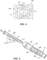
- FIGs. 2-7 Other embodiments and/or aspects of this disclosure are shown in Figs. 2-7 .
- the systems and methods described herein can be used to reduce size and weight of valves and related systems, e.g., by reducing the necessary linear length of the valve by having multiple ports in the same axial position.
- a transfer valve 100 includes a spool 101 comprising a first circumferential flow channel 103 at a first axial position of the spool 101 and a second circumferential flow channel 105 at a second axial position of the spool 101.
- the first circumferential flow channel 103 and the second circumferential flow channel 105 have different circumferential positions on the spool 101 and are defined only partially circumferentially.
- the flow channels 103, 105 can include any suitable axial or radial dimension.
- a sleeve 107 is disposed over the spool 101.
- the sleeve 107 includes at least three flow windows 109 defined through the sleeve 107 at a particular axial position of the sleeve 107.
- Each flow window 109 has a different circumferential position on the sleeve 107 as shown.
- the spool 101 and the sleeve 107 can be of any suitable shape (e.g., substantially cylindrical as shown, rectilinear, flat).
- the spool 101 is configured to translate within the sleeve 107 between a first position and a second position.
- the first circumferential flow channel 103 of the spool 101 is configured to fluidly connect a first plurality of the at least three windows 109 in the first position
- the second circumferential flow channel 105 is configured to connect a second plurality of the at least three windows 109 in the second position.
- the first plurality of windows 109 is different by at least one window 109 from the second plurality of windows 109.
- the spool 101 can include an at least partially axial channel portion 111 that connects the first circumferential flow channel 103 and the second circumferential flow channel 105.
- the axial channel can allow one window of the plurality to always be open.
- a window 109b may be an outlet window, and a window 109a can be an inlet window. While switching, window 109b can remain open while window 109a will get closed and then window 109c will be opened.
- the axial channel portion 111 is not required and the first circumferential flow channel 103 and the second circumferential flow channel 105 can be disconnected and/or discontinuous in any suitable manner.
- the axial channel portion 111 allows for constant communication with the common port, without restriction of the flow path.
- the axial channel portion 111 could be eliminated (e.g., by a barrier between circumferential flow channels 103, 105) and/or can incorporate a metering function of the two circumferential flow channels 103, 105 (e.g., variable area as a function of the spool stroke).
- the at least partially axial channel portion 111 can include any suitable shape (e.g., straight, circumferentially spiral).
- the at least partially axial channel portion 111 includes a partially toroidal shape and extends straight along in the axial direction.
- the spool 101 can include an anti-rotation slot 113 defined in a portion thereof for receiving an anti-rotation pin 115.
- the slot 113 can be dimensioned to allow translation between the first position and the second position, but to prevent rotation of the spool 101 within the sleeve 107.
- the sleeve 107 can include a pin hole 117 defined therethrough and configured to receive the anti-rotation pin 115.
- the valve 100 can include the anti-rotation pin 115 disposed in the pin hole 117 of the sleeve 107 and in the anti-rotation slot 113 of the spool 103.
- the valve 100 can include a housing 119 disposed over the sleeve 107 that includes a port 121 for each window (e.g., as shown in Fig. 2 ).
- at least one seal 123 e.g., as shown in Figs. 5A and 5B
- the at least one seal 123 can include at least one ladder seal or any other suitable seal and can be disposed in one or more sleeve seal slots 125.
- the spool 101 can include a plurality of sets of first and second circumferential flow channels 103, 105 in different axial positions.
- the spool 101 can include one or more seal channels 127 defined therein between the plurality of sets of channels 103, 105 as shown in Fig. 4 .
- the valve 100 can include a seal 129 (e.g., as shown in Figs. 5A and 5B ). disposed in each seal channel 127 of the spool 101, for example.
- the seals 129 in the seal channels 127 can be ring seals, for example, or any other suitable seal.
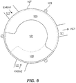
- the first plurality of the at least three windows 109 can include a first window 109a and a second window 109b in the first position.
- the second plurality can include a second window 109b and a third window 109c.
- Fig. 6 shows the transition between a first position and a second position in cross-section for this embodiment for example. This arrangement can allow switching between two sources and/or drains, for example (e.g., for a switching from a primary hydraulic system to a backup hydraulic system). Any other window 109 arrangements and fluid connections in the first and second positions are contemplated herein.
- an aircraft hydraulic system 700 can include any suitable embodiment of a transfer valve 100 as described herein.
- the valve 100 can be actuated via a pressurized circuit (e.g., having a solenoid valve). Any other suitable actuation (e.g., mechanical, electrical, etc.) is contemplated herein, and actuation can be manual or automated in any suitable manner.
- the transfer valve 100 can be used for any purpose in any application, e.g., hydraulic, fuel, oil, or other fluid system (e.g., for signaling).
- the valve 100 can be used with any system or flow scheme where switching of two or more pressure signals (e.g., two pressure signals as shown) happens at the same time.
- the spool 101 and/or the sleeve 107 can be made of metal (and/or any other suitable material).
- the spool 101 can be disposed in the sleeve 107 in a tight tolerance fit or in any other suitable manner.
- a method of actuating a transfer valve includes axially moving a spool between a first position and a second position relative to a sleeve surrounding the spool, and altering fluidic communication between a first plurality of circumferentially defined windows and a second plurality of circumferentially defined windows in the same axial position as the first plurality of circumferentially defined windows through the axial movement of the spool.
- Embodiments collapse the axial size of valves and reduce size/weight of valves.
- Embodiments improve the architecture of transfer valves in order to reduce weight and size of both the valve itself and the housing.
- Embodiments can drive two separate signal sources and an outlet signal into a single sealing location.
- the signal sources can be separated by a ladder seal.
- the valve can be timed to provide optimum flow connection.
- the switching between signal sources can be accomplished via a spool.
- Embodiments can be anti-rotated to align with the signal ports. With each signal source having its own land, the spool can accommodate seals between each signal source to greatly reduce leakage.
- Embodiments allow axial length compared to existing valves to decrease by about 25-50%, and leakage in valves can decrease by a large margin. Embodiments improve both the packaging of the valves and the performance. Embodiments can also be applied to combining multiple two position valves into the same valve in order to save weight and packaging. Reduced leakage of the valve may lead to a large reduction in the overall control leakage, which could lead to a smaller pump being required, reducing weight further.
Landscapes
- Engineering & Computer Science (AREA)
- General Engineering & Computer Science (AREA)
- Mechanical Engineering (AREA)
- Multiple-Way Valves (AREA)
Claims (15)
- Transferventil (100), umfassend:eine Spule (101), die einen ersten umlaufenden Strömungskanal (103) an einer ersten axialen Position der Spule (101) und einen zweiten umlaufenden Strömungskanal (105) an einer zweiten axialen Position der Spule (101) umfasst, wobei der erste umlaufende Strömungskanal (103) und der zweite umlaufende Strömungskanal (105) unterschiedliche Positionen in Umfangsrichtung aufweisen und nur teilweise umlaufend definiert sind; undeine Hülse (107), die über der Spule (101) angeordnet ist, wobei die Hülse (107) mindestens drei Öffnungen (109) beinhaltet, die durch die Hülse (107) definiert sind,wobei die Spule (101) dazu konfiguriert ist, innerhalb der Hülse (107) zwischen einer ersten Position und einer zweiten Position verschoben zu werden,wobei der erste umlaufende Strömungskanal (103) der Spule (101) dazu konfiguriert ist, in der ersten Position eine erste Vielzahl der mindestens drei Öffnungen (109) fluidisch zu verbinden, und der zweite umlaufende Strömungskanal (105) dazu konfiguriert ist, in der zweiten Position eine zweite Vielzahl der mindestens drei Öffnungen (109) fluidisch zu verbinden, wobei sich die erste Vielzahl von Öffnungen (109) in mindestens einer Öffnung von der zweiten Vielzahl von Öffnungen (109) unterscheidet, sodass beim Schalten aus einer Position in die andere eine erste Öffnung (109a) geschlossen und eine dritte Öffnung (109c) geöffnet wird, während eine zweite Öffnung (109b) offen bleibt,dadurch gekennzeichnet, dass die mindestens drei Öffnungen (109) an einer axialen Position der Hülse (107) definiert sind, wobei jede Öffnung (109) eine andere Position in Umfangsrichtung an der Hülse (107) aufweist.
- Ventil nach Anspruch 1, wobei die erste Vielzahl der mindestens drei Öffnungen (109) die erste Öffnung (109a) und die zweite Öffnung (109b) beinhaltet, wobei die zweite Vielzahl die zweite Öffnung (109b) und die dritte Öffnung (109c) beinhaltet.
- Ventil nach Anspruch 1 oder 2, wobei die Spule (101) ferner einen zumindest teilweise axialen Kanalabschnitt (111) beinhaltet, der den ersten umlaufenden Strömungskanal (103) und den zweiten umlaufenden Strömungskanal (105) verbindet.
- Ventil nach einem der vorhergehenden Ansprüche, wobei die Spule (101) einen in einem Abschnitt davon definierten Drehsicherungsschlitz (113) zum Aufnehmen eines Drehsicherungsstifts (115) beinhaltet, wobei der Schlitz (113) so bemessen ist, dass er eine Verschiebung zwischen der ersten Position und der zweiten Position ermöglicht, aber eine Drehung der Spule (101) innerhalb der Hülse verhindert.
- Ventil nach Anspruch 4, wobei die Hülse (107) ein Stiftloch (117) beinhaltet, das durch diese definiert und zum Aufnehmen des Drehsicherungsstifts (115) konfiguriert ist.
- Ventil nach Anspruch 5, ferner umfassend den Drehsicherungsstift (115), der in dem Stiftloch (117) der Hülse (107) und in dem Drehsicherungsschlitz (115) der Spule (101) angeordnet ist.
- Ventil nach einem der vorhergehenden Ansprüche, ferner umfassend ein Gehäuse (119), das über der Hülse (107) angeordnet ist und einen Einlass für jede der mindestens drei Öffnungen (109) beinhaltet.
- Ventil nach Anspruch 7, ferner umfassend mindestens eine Dichtung (129), die zwischen der Hülse (107) und dem Gehäuse (119) angeordnet ist, sodass jede Öffnung (109) zwischen der Hülse (107) und dem Gehäuse (119) fluidisch isoliert ist.
- Ventil nach Anspruch 8, wobei die mindestens eine Dichtung (129) mindestens eine Dichtung in Leiterform beinhaltet.
- Ventil nach einem der vorhergehenden Ansprüche, wobei die Spule (101) eine Vielzahl von Sätzen eines ersten und eines zweiten umlaufenden Strömungskanals (103, 105) an unterschiedlichen axialen Positionen beinhaltet.
- Ventil nach Anspruch 10, wobei die Spule (101) einen oder mehrere Dichtungskanäle beinhaltet, die in dieser zwischen der Vielzahl von Sätzen eines ersten und eines zweiten umlaufenden Strömungskanals definiert sind.
- Ventil nach Anspruch 11, ferner umfassend eine Dichtung, die in jedem Dichtungskanal angeordnet ist und
wobei es sich vorzugsweise bei den Dichtungen um Ringdichtungen handelt. - Flugzeughydrauliksystem (700), das ein Transferventil nach Anspruch 1 umfasst.
- System nach Anspruch 13, wobei die erste Vielzahl der mindestens drei Öffnungen (109) die erste Öffnung (109a) und die zweite Öffnung (109b) beinhaltet, wobei die zweite Vielzahl die zweite Öffnung (109b) und die dritte Öffnung (109c) beinhaltet.
- Verfahren zum Betätigen eines Transferventils nach Anspruch 1, umfassend:axiales Bewegen der Spule (101) zwischen der ersten Position und der zweiten Position relativ zu der die Spule (101) umgebenden Hülse (107); undVerändern der Fluidverbindung zwischen der ersten Vielzahl in Umfangsrichtung definierter Öffnungen (109) und der zweiten Vielzahl in Umfangsrichtung definierter Öffnungen (109), die sich an der gleichen axialen Position befindet wie die erste Vielzahl in Umfangsrichtung definierter Öffnungen (109), durch die axiale Bewegung der Spule (101),wobei das Verändern der Fluidverbindung ein Schließen der ersten Öffnung (109a) und Öffnen der dritten Öffnung (109c), während die zweite Öffnung (109b) offen bleibt, beinhaltet.
Applications Claiming Priority (1)
| Application Number | Priority Date | Filing Date | Title |
|---|---|---|---|
| US15/617,480 US10711903B2 (en) | 2017-06-08 | 2017-06-08 | Transfer valves |
Publications (2)
| Publication Number | Publication Date |
|---|---|
| EP3412943A1 EP3412943A1 (de) | 2018-12-12 |
| EP3412943B1 true EP3412943B1 (de) | 2021-08-04 |
Family
ID=62567354
Family Applications (1)
| Application Number | Title | Priority Date | Filing Date |
|---|---|---|---|
| EP18176054.7A Active EP3412943B1 (de) | 2017-06-08 | 2018-06-05 | Entnahmeventile |
Country Status (2)
| Country | Link |
|---|---|
| US (1) | US10711903B2 (de) |
| EP (1) | EP3412943B1 (de) |
Families Citing this family (6)
| Publication number | Priority date | Publication date | Assignee | Title |
|---|---|---|---|---|
| KR102842802B1 (ko) * | 2020-09-09 | 2025-08-05 | 현대자동차 주식회사 | 다유로 냉각수 밸브 |
| US12083856B2 (en) * | 2020-10-29 | 2024-09-10 | Rivian Ip Holdings, Llc | Integrated thermal management system for a vehicle |
| WO2023042775A1 (ja) * | 2021-09-17 | 2023-03-23 | 株式会社Ihi | スプール弁 |
| US20250044816A1 (en) * | 2023-07-31 | 2025-02-06 | Hamilton Sundstrand Corporation | Valve systems |
| US12163537B1 (en) * | 2023-10-20 | 2024-12-10 | Hamilton Sundstrand Corporation | Three way transfer valve for parallel electrohydraulic servo valve control of actuator |
| US12595854B2 (en) | 2024-09-17 | 2026-04-07 | Hamilton Sundstrand Corporation | Compact hydraulically centered three-way transfer valve |
Citations (1)
| Publication number | Priority date | Publication date | Assignee | Title |
|---|---|---|---|---|
| US20070265581A1 (en) * | 2006-05-15 | 2007-11-15 | Tyco Healthcare Group Lp | Liquid Coinjector |
Family Cites Families (26)
| Publication number | Priority date | Publication date | Assignee | Title |
|---|---|---|---|---|
| GB569829A (en) | 1943-10-04 | 1945-06-11 | Integral Ltd | Improvements in or relating to hydraulic control valves |
| US4674526A (en) | 1986-09-12 | 1987-06-23 | Bellofram Corporation | Switching valve |
| US4741364A (en) * | 1987-06-12 | 1988-05-03 | Deere & Company | Pilot-operated valve with load pressure feedback |
| WO1995018324A1 (en) * | 1993-12-28 | 1995-07-06 | Toto Ltd. | Hot and cold water mixing device |
| DE4400760C2 (de) | 1994-01-13 | 1997-03-27 | Festo Kg | Mehrwegeventil |
| US6116276A (en) | 1998-02-09 | 2000-09-12 | Sturman Bg, Llc | Balance latching fluid valve |
| JP4172211B2 (ja) * | 2002-06-06 | 2008-10-29 | 株式会社デンソー | 流量制御装置 |
| FR2844571B1 (fr) | 2002-09-18 | 2008-02-29 | Valeo Thermique Moteur Sa | Vanne de commande pour un circuit de fluide et circuit comportant cette vanne |
| US7766041B2 (en) * | 2006-08-08 | 2010-08-03 | Delta Power Company | Flow force reduction by incremental pressure drop |
| WO2008121365A1 (en) * | 2007-03-31 | 2008-10-09 | Microstaq, Inc. | Pilot operated spool valve |
| WO2009088504A1 (en) * | 2008-01-07 | 2009-07-16 | Vanderbilt University | Solenoid valve assembly |
| US8186378B2 (en) * | 2008-04-15 | 2012-05-29 | Husco Automotive Holdings, LLC | Filter band for an electrohydraulic valve |
| DE102009014029B4 (de) | 2009-03-23 | 2012-10-25 | Kreyenborg Verwaltungen Und Beteiligungen Gmbh & Co. Kg | Umschaltventil für eine Kunststoffschmelze |
| US8397687B2 (en) * | 2010-10-26 | 2013-03-19 | Delphi Technologies, Inc. | Axially compact camshaft phaser |
| CN101968128B (zh) | 2010-11-08 | 2012-04-18 | 浙江盾安机械有限公司 | 大容量四通换向阀 |
| CN202302095U (zh) | 2011-09-22 | 2012-07-04 | 深圳成霖洁具股份有限公司 | 混温阀 |
| US9625042B2 (en) * | 2012-10-08 | 2017-04-18 | First Sales Llc | Fluid additive control valve |
| US9175789B2 (en) * | 2012-10-23 | 2015-11-03 | Hamilton Sundstrand Corporation | Pressure regulating valve |
| US9249800B2 (en) * | 2012-11-01 | 2016-02-02 | Hamilton Sundstrand Corporation | Bypass directional control valve |
| JP6090278B2 (ja) * | 2013-11-11 | 2017-03-08 | 株式会社デンソー | バルブ装置 |
| US20150233480A1 (en) * | 2014-02-20 | 2015-08-20 | Hamilton Sundstrand Corporation | Pressure regulating valves for electrical generators |
| US9422840B2 (en) * | 2014-06-24 | 2016-08-23 | Hilite Germany Gmbh | Hydraulic valve for an internal combustion engine |
| WO2016021280A1 (ja) * | 2014-08-04 | 2016-02-11 | 日立オートモティブシステムズ株式会社 | 油圧制御弁及び該油圧制御弁が用いられた内燃機関のバルブタイミング制御装置 |
| US10508745B2 (en) * | 2015-09-18 | 2019-12-17 | The Oilgear Company | Valve assembly |
| DE102015225927A1 (de) * | 2015-12-18 | 2017-06-22 | Robert Bosch Gmbh | Ventilkolben und Schieberventil mit einem Ventilkolben |
| CN205781058U (zh) | 2016-05-19 | 2016-12-07 | 江苏恒达动力科技发展股份有限公司 | 一种双连通切换的高压四通电磁阀 |
-
2017
- 2017-06-08 US US15/617,480 patent/US10711903B2/en active Active
-
2018
- 2018-06-05 EP EP18176054.7A patent/EP3412943B1/de active Active
Patent Citations (1)
| Publication number | Priority date | Publication date | Assignee | Title |
|---|---|---|---|---|
| US20070265581A1 (en) * | 2006-05-15 | 2007-11-15 | Tyco Healthcare Group Lp | Liquid Coinjector |
Also Published As
| Publication number | Publication date |
|---|---|
| US20180355984A1 (en) | 2018-12-13 |
| EP3412943A1 (de) | 2018-12-12 |
| US10711903B2 (en) | 2020-07-14 |
Similar Documents
| Publication | Publication Date | Title |
|---|---|---|
| EP3412943B1 (de) | Entnahmeventile | |
| US9032988B2 (en) | Stackable shuttle valve | |
| CN104895859B (zh) | 具有负载保持功能的阀组件 | |
| MX2013014917A (es) | Valvula modular normalmente abierta, de multiples puertos, con asiento roscado. | |
| US8528600B2 (en) | Hydraulic valve | |
| WO2019122462A1 (en) | Flow control valve | |
| US9091355B2 (en) | Main stage in-line pressure control cartridge with optional reverse flow function | |
| US20180163879A1 (en) | Subsea Valve With Non-Circular Sliding Metal Seals | |
| US20080217573A1 (en) | Poppet cartridge with two-piece poppet and piston coupled by a floating coupler | |
| CN110735929A (zh) | 一种先导式电磁阀 | |
| CN118375465A (zh) | 一种极薄煤层液压支架用换向阀以及换向方法 | |
| US20100147388A1 (en) | Directional gate valve | |
| CN206845202U (zh) | 片式电液控换向阀 | |
| JPH0463272B2 (de) | ||
| EP3458749B1 (de) | Von vorne eingesetzte sitzdichtung | |
| CN212657082U (zh) | 换向阀 | |
| JP5730369B2 (ja) | 切換弁 | |
| US6408735B1 (en) | Actuator | |
| CN111828419A (zh) | 液压换向阀 | |
| US3092140A (en) | Releasable balanced fluid coupling | |
| US20210254639A1 (en) | Hydraulic control valves for ram air turbine stow actuators | |
| CN213236189U (zh) | 一种高响应的二通插装阀 | |
| US12049802B1 (en) | Fluid diverter system with chamber valves and method of use | |
| JPH10325476A (ja) | 切換弁 | |
| US3153528A (en) | Spool type control valve |
Legal Events
| Date | Code | Title | Description |
|---|---|---|---|
| PUAI | Public reference made under article 153(3) epc to a published international application that has entered the european phase |
Free format text: ORIGINAL CODE: 0009012 |
|
| STAA | Information on the status of an ep patent application or granted ep patent |
Free format text: STATUS: THE APPLICATION HAS BEEN PUBLISHED |
|
| AK | Designated contracting states |
Kind code of ref document: A1 Designated state(s): AL AT BE BG CH CY CZ DE DK EE ES FI FR GB GR HR HU IE IS IT LI LT LU LV MC MK MT NL NO PL PT RO RS SE SI SK SM TR |
|
| AX | Request for extension of the european patent |
Extension state: BA ME |
|
| RIN1 | Information on inventor provided before grant (corrected) |
Inventor name: CORETTO, AUGUST M. Inventor name: BOSTIGA, RICHARD H. Inventor name: SUSCA, RYAN Inventor name: RICKIS, AARON Inventor name: GRADISCHER, GLENN Inventor name: MAROCCHINI, FRANCIS P. |
|
| STAA | Information on the status of an ep patent application or granted ep patent |
Free format text: STATUS: REQUEST FOR EXAMINATION WAS MADE |
|
| 17P | Request for examination filed |
Effective date: 20190612 |
|
| RBV | Designated contracting states (corrected) |
Designated state(s): AL AT BE BG CH CY CZ DE DK EE ES FI FR GB GR HR HU IE IS IT LI LT LU LV MC MK MT NL NO PL PT RO RS SE SI SK SM TR |
|
| STAA | Information on the status of an ep patent application or granted ep patent |
Free format text: STATUS: EXAMINATION IS IN PROGRESS |
|
| 17Q | First examination report despatched |
Effective date: 20190820 |
|
| GRAP | Despatch of communication of intention to grant a patent |
Free format text: ORIGINAL CODE: EPIDOSNIGR1 |
|
| STAA | Information on the status of an ep patent application or granted ep patent |
Free format text: STATUS: GRANT OF PATENT IS INTENDED |
|
| INTG | Intention to grant announced |
Effective date: 20210210 |
|
| GRAS | Grant fee paid |
Free format text: ORIGINAL CODE: EPIDOSNIGR3 |
|
| GRAA | (expected) grant |
Free format text: ORIGINAL CODE: 0009210 |
|
| STAA | Information on the status of an ep patent application or granted ep patent |
Free format text: STATUS: THE PATENT HAS BEEN GRANTED |
|
| AK | Designated contracting states |
Kind code of ref document: B1 Designated state(s): AL AT BE BG CH CY CZ DE DK EE ES FI FR GB GR HR HU IE IS IT LI LT LU LV MC MK MT NL NO PL PT RO RS SE SI SK SM TR |
|
| REG | Reference to a national code |
Ref country code: GB Ref legal event code: FG4D |
|
| REG | Reference to a national code |
Ref country code: AT Ref legal event code: REF Ref document number: 1417304 Country of ref document: AT Kind code of ref document: T Effective date: 20210815 |
|
| REG | Reference to a national code |
Ref country code: CH Ref legal event code: EP |
|
| REG | Reference to a national code |
Ref country code: DE Ref legal event code: R096 Ref document number: 602018021055 Country of ref document: DE |
|
| REG | Reference to a national code |
Ref country code: IE Ref legal event code: FG4D |
|
| REG | Reference to a national code |
Ref country code: LT Ref legal event code: MG9D |
|
| REG | Reference to a national code |
Ref country code: NL Ref legal event code: MP Effective date: 20210804 |
|
| REG | Reference to a national code |
Ref country code: AT Ref legal event code: MK05 Ref document number: 1417304 Country of ref document: AT Kind code of ref document: T Effective date: 20210804 |
|
| PG25 | Lapsed in a contracting state [announced via postgrant information from national office to epo] |
Ref country code: HR Free format text: LAPSE BECAUSE OF FAILURE TO SUBMIT A TRANSLATION OF THE DESCRIPTION OR TO PAY THE FEE WITHIN THE PRESCRIBED TIME-LIMIT Effective date: 20210804 Ref country code: ES Free format text: LAPSE BECAUSE OF FAILURE TO SUBMIT A TRANSLATION OF THE DESCRIPTION OR TO PAY THE FEE WITHIN THE PRESCRIBED TIME-LIMIT Effective date: 20210804 Ref country code: FI Free format text: LAPSE BECAUSE OF FAILURE TO SUBMIT A TRANSLATION OF THE DESCRIPTION OR TO PAY THE FEE WITHIN THE PRESCRIBED TIME-LIMIT Effective date: 20210804 Ref country code: RS Free format text: LAPSE BECAUSE OF FAILURE TO SUBMIT A TRANSLATION OF THE DESCRIPTION OR TO PAY THE FEE WITHIN THE PRESCRIBED TIME-LIMIT Effective date: 20210804 Ref country code: SE Free format text: LAPSE BECAUSE OF FAILURE TO SUBMIT A TRANSLATION OF THE DESCRIPTION OR TO PAY THE FEE WITHIN THE PRESCRIBED TIME-LIMIT Effective date: 20210804 Ref country code: NO Free format text: LAPSE BECAUSE OF FAILURE TO SUBMIT A TRANSLATION OF THE DESCRIPTION OR TO PAY THE FEE WITHIN THE PRESCRIBED TIME-LIMIT Effective date: 20211104 Ref country code: PT Free format text: LAPSE BECAUSE OF FAILURE TO SUBMIT A TRANSLATION OF THE DESCRIPTION OR TO PAY THE FEE WITHIN THE PRESCRIBED TIME-LIMIT Effective date: 20211206 Ref country code: AT Free format text: LAPSE BECAUSE OF FAILURE TO SUBMIT A TRANSLATION OF THE DESCRIPTION OR TO PAY THE FEE WITHIN THE PRESCRIBED TIME-LIMIT Effective date: 20210804 Ref country code: BG Free format text: LAPSE BECAUSE OF FAILURE TO SUBMIT A TRANSLATION OF THE DESCRIPTION OR TO PAY THE FEE WITHIN THE PRESCRIBED TIME-LIMIT Effective date: 20211104 Ref country code: LT Free format text: LAPSE BECAUSE OF FAILURE TO SUBMIT A TRANSLATION OF THE DESCRIPTION OR TO PAY THE FEE WITHIN THE PRESCRIBED TIME-LIMIT Effective date: 20210804 |
|
| PG25 | Lapsed in a contracting state [announced via postgrant information from national office to epo] |
Ref country code: PL Free format text: LAPSE BECAUSE OF FAILURE TO SUBMIT A TRANSLATION OF THE DESCRIPTION OR TO PAY THE FEE WITHIN THE PRESCRIBED TIME-LIMIT Effective date: 20210804 Ref country code: LV Free format text: LAPSE BECAUSE OF FAILURE TO SUBMIT A TRANSLATION OF THE DESCRIPTION OR TO PAY THE FEE WITHIN THE PRESCRIBED TIME-LIMIT Effective date: 20210804 Ref country code: GR Free format text: LAPSE BECAUSE OF FAILURE TO SUBMIT A TRANSLATION OF THE DESCRIPTION OR TO PAY THE FEE WITHIN THE PRESCRIBED TIME-LIMIT Effective date: 20211105 |
|
| PG25 | Lapsed in a contracting state [announced via postgrant information from national office to epo] |
Ref country code: NL Free format text: LAPSE BECAUSE OF FAILURE TO SUBMIT A TRANSLATION OF THE DESCRIPTION OR TO PAY THE FEE WITHIN THE PRESCRIBED TIME-LIMIT Effective date: 20210804 |
|
| PG25 | Lapsed in a contracting state [announced via postgrant information from national office to epo] |
Ref country code: DK Free format text: LAPSE BECAUSE OF FAILURE TO SUBMIT A TRANSLATION OF THE DESCRIPTION OR TO PAY THE FEE WITHIN THE PRESCRIBED TIME-LIMIT Effective date: 20210804 |
|
| REG | Reference to a national code |
Ref country code: DE Ref legal event code: R097 Ref document number: 602018021055 Country of ref document: DE |
|
| PG25 | Lapsed in a contracting state [announced via postgrant information from national office to epo] |
Ref country code: SM Free format text: LAPSE BECAUSE OF FAILURE TO SUBMIT A TRANSLATION OF THE DESCRIPTION OR TO PAY THE FEE WITHIN THE PRESCRIBED TIME-LIMIT Effective date: 20210804 Ref country code: SK Free format text: LAPSE BECAUSE OF FAILURE TO SUBMIT A TRANSLATION OF THE DESCRIPTION OR TO PAY THE FEE WITHIN THE PRESCRIBED TIME-LIMIT Effective date: 20210804 Ref country code: RO Free format text: LAPSE BECAUSE OF FAILURE TO SUBMIT A TRANSLATION OF THE DESCRIPTION OR TO PAY THE FEE WITHIN THE PRESCRIBED TIME-LIMIT Effective date: 20210804 Ref country code: EE Free format text: LAPSE BECAUSE OF FAILURE TO SUBMIT A TRANSLATION OF THE DESCRIPTION OR TO PAY THE FEE WITHIN THE PRESCRIBED TIME-LIMIT Effective date: 20210804 Ref country code: CZ Free format text: LAPSE BECAUSE OF FAILURE TO SUBMIT A TRANSLATION OF THE DESCRIPTION OR TO PAY THE FEE WITHIN THE PRESCRIBED TIME-LIMIT Effective date: 20210804 Ref country code: AL Free format text: LAPSE BECAUSE OF FAILURE TO SUBMIT A TRANSLATION OF THE DESCRIPTION OR TO PAY THE FEE WITHIN THE PRESCRIBED TIME-LIMIT Effective date: 20210804 |
|
| PLBE | No opposition filed within time limit |
Free format text: ORIGINAL CODE: 0009261 |
|
| STAA | Information on the status of an ep patent application or granted ep patent |
Free format text: STATUS: NO OPPOSITION FILED WITHIN TIME LIMIT |
|
| 26N | No opposition filed |
Effective date: 20220506 |
|
| PG25 | Lapsed in a contracting state [announced via postgrant information from national office to epo] |
Ref country code: IT Free format text: LAPSE BECAUSE OF FAILURE TO SUBMIT A TRANSLATION OF THE DESCRIPTION OR TO PAY THE FEE WITHIN THE PRESCRIBED TIME-LIMIT Effective date: 20210804 |
|
| PG25 | Lapsed in a contracting state [announced via postgrant information from national office to epo] |
Ref country code: SI Free format text: LAPSE BECAUSE OF FAILURE TO SUBMIT A TRANSLATION OF THE DESCRIPTION OR TO PAY THE FEE WITHIN THE PRESCRIBED TIME-LIMIT Effective date: 20210804 |
|
| PG25 | Lapsed in a contracting state [announced via postgrant information from national office to epo] |
Ref country code: MC Free format text: LAPSE BECAUSE OF FAILURE TO SUBMIT A TRANSLATION OF THE DESCRIPTION OR TO PAY THE FEE WITHIN THE PRESCRIBED TIME-LIMIT Effective date: 20210804 |
|
| REG | Reference to a national code |
Ref country code: CH Ref legal event code: PL |
|
| REG | Reference to a national code |
Ref country code: BE Ref legal event code: MM Effective date: 20220630 |
|
| PG25 | Lapsed in a contracting state [announced via postgrant information from national office to epo] |
Ref country code: LU Free format text: LAPSE BECAUSE OF NON-PAYMENT OF DUE FEES Effective date: 20220605 Ref country code: LI Free format text: LAPSE BECAUSE OF NON-PAYMENT OF DUE FEES Effective date: 20220630 Ref country code: IE Free format text: LAPSE BECAUSE OF NON-PAYMENT OF DUE FEES Effective date: 20220605 Ref country code: CH Free format text: LAPSE BECAUSE OF NON-PAYMENT OF DUE FEES Effective date: 20220630 |
|
| PG25 | Lapsed in a contracting state [announced via postgrant information from national office to epo] |
Ref country code: BE Free format text: LAPSE BECAUSE OF NON-PAYMENT OF DUE FEES Effective date: 20220630 |
|
| P01 | Opt-out of the competence of the unified patent court (upc) registered |
Effective date: 20230522 |
|
| PG25 | Lapsed in a contracting state [announced via postgrant information from national office to epo] |
Ref country code: HU Free format text: LAPSE BECAUSE OF FAILURE TO SUBMIT A TRANSLATION OF THE DESCRIPTION OR TO PAY THE FEE WITHIN THE PRESCRIBED TIME-LIMIT; INVALID AB INITIO Effective date: 20180605 |
|
| PG25 | Lapsed in a contracting state [announced via postgrant information from national office to epo] |
Ref country code: MK Free format text: LAPSE BECAUSE OF FAILURE TO SUBMIT A TRANSLATION OF THE DESCRIPTION OR TO PAY THE FEE WITHIN THE PRESCRIBED TIME-LIMIT Effective date: 20210804 Ref country code: CY Free format text: LAPSE BECAUSE OF FAILURE TO SUBMIT A TRANSLATION OF THE DESCRIPTION OR TO PAY THE FEE WITHIN THE PRESCRIBED TIME-LIMIT Effective date: 20210804 |
|
| PG25 | Lapsed in a contracting state [announced via postgrant information from national office to epo] |
Ref country code: TR Free format text: LAPSE BECAUSE OF FAILURE TO SUBMIT A TRANSLATION OF THE DESCRIPTION OR TO PAY THE FEE WITHIN THE PRESCRIBED TIME-LIMIT Effective date: 20210804 |
|
| PG25 | Lapsed in a contracting state [announced via postgrant information from national office to epo] |
Ref country code: MT Free format text: LAPSE BECAUSE OF FAILURE TO SUBMIT A TRANSLATION OF THE DESCRIPTION OR TO PAY THE FEE WITHIN THE PRESCRIBED TIME-LIMIT Effective date: 20210804 |
|
| PGFP | Annual fee paid to national office [announced via postgrant information from national office to epo] |
Ref country code: DE Payment date: 20250520 Year of fee payment: 8 |
|
| PGFP | Annual fee paid to national office [announced via postgrant information from national office to epo] |
Ref country code: GB Payment date: 20250520 Year of fee payment: 8 |
|
| PGFP | Annual fee paid to national office [announced via postgrant information from national office to epo] |
Ref country code: FR Payment date: 20250520 Year of fee payment: 8 |