WO2023042775A1 - スプール弁 - Google Patents
スプール弁 Download PDFInfo
- Publication number
- WO2023042775A1 WO2023042775A1 PCT/JP2022/033990 JP2022033990W WO2023042775A1 WO 2023042775 A1 WO2023042775 A1 WO 2023042775A1 JP 2022033990 W JP2022033990 W JP 2022033990W WO 2023042775 A1 WO2023042775 A1 WO 2023042775A1
- Authority
- WO
- WIPO (PCT)
- Prior art keywords
- spool
- sleeve
- outlet port
- working fluid
- circumferential direction
- Prior art date
Links
- 239000012530 fluid Substances 0.000 claims abstract description 65
- 238000001514 detection method Methods 0.000 claims abstract description 10
- 230000002093 peripheral effect Effects 0.000 description 16
- 230000003068 static effect Effects 0.000 description 10
- 230000000052 comparative effect Effects 0.000 description 8
- 238000010586 diagram Methods 0.000 description 8
- 230000007423 decrease Effects 0.000 description 7
- 230000004308 accommodation Effects 0.000 description 6
- 238000004891 communication Methods 0.000 description 4
- 238000013459 approach Methods 0.000 description 3
- 230000001133 acceleration Effects 0.000 description 1
- 230000015572 biosynthetic process Effects 0.000 description 1
- 230000003749 cleanliness Effects 0.000 description 1
- 230000006835 compression Effects 0.000 description 1
- 238000007906 compression Methods 0.000 description 1
- 239000000356 contaminant Substances 0.000 description 1
- 230000008602 contraction Effects 0.000 description 1
- 230000005489 elastic deformation Effects 0.000 description 1
- 239000000446 fuel Substances 0.000 description 1
- 239000000463 material Substances 0.000 description 1
- 238000012986 modification Methods 0.000 description 1
- 230000004048 modification Effects 0.000 description 1
- 230000010349 pulsation Effects 0.000 description 1
- 238000007789 sealing Methods 0.000 description 1
Images


Classifications
-
- G—PHYSICS
- G05—CONTROLLING; REGULATING
- G05D—SYSTEMS FOR CONTROLLING OR REGULATING NON-ELECTRIC VARIABLES
- G05D16/00—Control of fluid pressure
- G05D16/04—Control of fluid pressure without auxiliary power
- G05D16/10—Control of fluid pressure without auxiliary power the sensing element being a piston or plunger
-
- F—MECHANICAL ENGINEERING; LIGHTING; HEATING; WEAPONS; BLASTING
- F16—ENGINEERING ELEMENTS AND UNITS; GENERAL MEASURES FOR PRODUCING AND MAINTAINING EFFECTIVE FUNCTIONING OF MACHINES OR INSTALLATIONS; THERMAL INSULATION IN GENERAL
- F16K—VALVES; TAPS; COCKS; ACTUATING-FLOATS; DEVICES FOR VENTING OR AERATING
- F16K11/00—Multiple-way valves, e.g. mixing valves; Pipe fittings incorporating such valves
- F16K11/02—Multiple-way valves, e.g. mixing valves; Pipe fittings incorporating such valves with all movable sealing faces moving as one unit
- F16K11/06—Multiple-way valves, e.g. mixing valves; Pipe fittings incorporating such valves with all movable sealing faces moving as one unit comprising only sliding valves, i.e. sliding closure elements
- F16K11/065—Multiple-way valves, e.g. mixing valves; Pipe fittings incorporating such valves with all movable sealing faces moving as one unit comprising only sliding valves, i.e. sliding closure elements with linearly sliding closure members
- F16K11/07—Multiple-way valves, e.g. mixing valves; Pipe fittings incorporating such valves with all movable sealing faces moving as one unit comprising only sliding valves, i.e. sliding closure elements with linearly sliding closure members with cylindrical slides
- F16K11/0712—Multiple-way valves, e.g. mixing valves; Pipe fittings incorporating such valves with all movable sealing faces moving as one unit comprising only sliding valves, i.e. sliding closure elements with linearly sliding closure members with cylindrical slides comprising particular spool-valve sealing means
-
- F—MECHANICAL ENGINEERING; LIGHTING; HEATING; WEAPONS; BLASTING
- F16—ENGINEERING ELEMENTS AND UNITS; GENERAL MEASURES FOR PRODUCING AND MAINTAINING EFFECTIVE FUNCTIONING OF MACHINES OR INSTALLATIONS; THERMAL INSULATION IN GENERAL
- F16K—VALVES; TAPS; COCKS; ACTUATING-FLOATS; DEVICES FOR VENTING OR AERATING
- F16K47/00—Means in valves for absorbing fluid energy
- F16K47/02—Means in valves for absorbing fluid energy for preventing water-hammer or noise
- F16K47/023—Means in valves for absorbing fluid energy for preventing water-hammer or noise for preventing water-hammer, e.g. damping of the valve movement
-
- G—PHYSICS
- G05—CONTROLLING; REGULATING
- G05D—SYSTEMS FOR CONTROLLING OR REGULATING NON-ELECTRIC VARIABLES
- G05D16/00—Control of fluid pressure
- G05D16/04—Control of fluid pressure without auxiliary power
- G05D16/10—Control of fluid pressure without auxiliary power the sensing element being a piston or plunger
- G05D16/101—Control of fluid pressure without auxiliary power the sensing element being a piston or plunger the controller being arranged as a multiple-way valve
Definitions
- the present disclosure relates to spool valves.
- a spool valve is a valve that has a sleeve and a spool housed in the sleeve, and opens and closes a flow path by movement of the spool.
- the sleeve is provided with an accommodation hole for the spool, and is provided with an inlet port and an outlet port for the working fluid on its side surface.
- the spool has a land portion (large diameter portion) having an outer diameter approximately equal to the diameter of the housing hole of the sleeve, and a groove portion (small diameter portion) recessed radially inward from the outer peripheral surface of the land portion.
- the groove has a width that allows communication between the inlet port and the outlet port. The opening of the spool valve is adjusted according to the position of the groove due to the movement of the spool.
- Patent document 1 discloses a spool type pressure control valve for the purpose of suppressing this pulsation.
- the pressure control valve and the flow control valve should be able to control the pressure of the working fluid to be constant with respect to increases and decreases in the flow rate of the working fluid.
- these valves have a so-called override characteristic in which the pressure of the working fluid increases as the flow rate of the working fluid increases.
- the fluid forces mentioned above also affect this override characteristic. For example, as the fluid force increases, the ratio of the pressure change of the working fluid to the flow rate change of the working fluid increases, making it difficult to control the pressure or flow rate.
- An object of the present disclosure is to provide a spool valve that suppresses the influence of fluid force on override characteristics and that can be applied to pressure control valves or flow control valves.
- a spool valve includes an axially extending sleeve including an inlet port and an outlet port for a working fluid, a spool movably accommodated in the sleeve in the axial direction, and the spool a biasing device including a biasing member that presses the proximal end of the spool toward the distal end of the spool; and a pressure detection port for the working fluid that opens toward the distal end of the spool, and the outlet port includes a plurality of slits, said plurality of slits being spaced circumferentially of said sleeve and extending in said axial direction.
- the outlet port may be formed in a plurality of regions that define the outer shape of the outlet port and are arranged at intervals in the circumferential direction.
- the outlet port may be divided into a first portion and a second portion located further from the inlet port than the first portion.
- the width of the first portion along the circumferential direction of the sleeve may increase toward the second portion.
- the width of the second portion along the circumferential direction of the sleeve may be constant.
- the plurality of slits may be formed over the entire circumferential direction while being spaced at predetermined intervals in the circumferential direction.
- a spool valve that suppresses the influence of fluid force on override characteristics and that can be applied to pressure control valves or flow control valves.
- FIG. 1 is a perspective view of a spool valve according to one embodiment of the present disclosure
- FIG. 1 is a cross-sectional view of a spool valve including a shaft
- FIG. 3 is an enlarged cross-sectional view of the periphery of a groove portion of the spool shown in FIG. 2
- FIG. 3 is a cross-sectional view of the spool valve, where (a) is a cross-sectional view taken along line IVA-IVA in FIG. 2 and (b) is a cross-sectional view taken along line IVB-IVB in FIG. 2;
- FIG. 1 is a perspective view of a spool valve according to one embodiment of the present disclosure
- FIG. 1 is a cross-sectional view of a spool valve including a shaft
- FIG. 3 is an enlarged cross-sectional view of the periphery of a groove portion of the spool shown in FIG. 2
- FIG. FIG. 3 is a cross-sectional view of the s
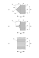
- FIG. 4 is a plan development view showing several examples of outlet ports viewed from the radial direction, (a) showing a first example of the outlet port, (b) showing a second example of the outlet port, (c ) shows a third example of the outlet port.
- FIG. 2 is a diagram showing the results of numerical analysis using CFD (Computational Fluid Dynamics) for the velocity distribution of the jet on a cross section including the axis, (a) is a diagram showing the velocity distribution of the jet in a comparative example, and (b) is the present It is a figure which shows the velocity distribution of the jet in embodiment.
- CFD Computer Fluid Dynamics
- FIG. 4 is a diagram showing the results of numerical analysis using CFD for the static pressure distribution in the groove near the outlet port on a cross section perpendicular to the axis, (a) showing the static pressure distribution in a comparative example, (b) 4 is a diagram showing a static pressure distribution in this embodiment;
- FIG. FIG. 4 is a graph showing changes in fluid force with respect to the opening area of the outlet port;
- the spool valve according to this embodiment can be applied as a pressure control valve or a flow control valve in an environment where electrical control is difficult, such as an aircraft fuel supply system.
- FIG. 1 is a perspective view of the spool valve 1
- FIG. 2 is a sectional view of the spool valve 1 including the shaft 2.
- FIG. FIG. 3 is an enlarged cross-sectional view of the periphery of the groove portion 23 of the spool 20 shown in FIG. 4 is a sectional view of the spool valve 1, (a) is a sectional view taken along line IVA-IVA in FIG. 2, and (b) is a sectional view taken along line IVB-IVB in FIG.
- the extending direction of the shaft 2 will be called the axial direction AD
- the circumferential direction and the radial direction around the shaft 2 will be called the circumferential direction CD and the radial direction RD, respectively.
- Axis 2 is the central axis of sleeve 10 (described later) and spool 20 (described later).
- the direction in which the spool 20 opens the outlet port 12 of the sleeve 10 (to the right in FIG. 2) is called the opening direction
- the direction in which the spool 20 closes the outlet port 12 of the sleeve 10 to the left in FIG. 2) is called the closing direction. Both the opening and closing directions are parallel to the axial direction AD.
- the spool valve 1 As shown in FIG. 1, the spool valve 1 according to this embodiment has a substantially cylindrical outer shape extending in the axial direction AD.
- the spool valve 1 comprises a sleeve 10 , a spool (piston) 20 and a biasing device 30 .
- the spool valve 1 is attached to the housing 40 by inserting it into an attachment hole 43 formed in the housing 40, for example.
- the sleeve 10 is a hollow cylindrical member extending in the axial direction AD, and accommodates the spool 20 in the accommodation hole 13 so as to be movable in the axial direction AD.
- a receiving hole 13 is formed in the sleeve 10 and extends in the axial direction AD about the axis 2 .
- An inlet port 11 and an outlet port 12 are provided on the outer peripheral surface 10 a of the sleeve 10 .
- the inlet port 11 is an inlet for working fluid and communicates with an inlet passage 41 formed in the housing 40 .
- the inlet port 11 has a predetermined width in the axial direction AD, and is formed over the entire circumferential direction CD except where the ribs 14 are provided. Also, the inlet port 11 always communicates with the groove portion 23 of the spool 20 .
- the outlet port 12 is located between the inlet port 11 and the proximal end 20a of the spool 20.
- the outlet port 12 is an outlet for working fluid and communicates with an outlet passage 42 formed in the housing 40 .
- the outlet ports 12 are formed in a plurality of regions 15 (FIG. 5) arranged at intervals in the circumferential direction CD. Each region 15 defines the contour of the outlet port 12 .
- the regions 15 are, for example, evenly spaced along the circumferential direction CD (eg, every 90° around the axis 2).
- exit port 12 includes a plurality of slits (slots, openings) 16 .
- the plurality of slits 16 are arranged at intervals in the circumferential direction CD and extend parallel to each other in the axial direction AD.
- the plurality of slits 16 are parallel to one plane that includes the axis 2 and extends in the radial direction RD (see FIG. 4B). Two adjacent slits 16, 16 are separated by a rib 19 therebetween.
- the widths of the slits 16 and the ribs 19 in the circumferential direction CD may be the same or different.
- the widths of the plurality of slits 16 may be constant or different from each other. The same applies to the widths of the plurality of ribs 19 as well.
- the outlet port 12 is divided into a first portion (first segment) 17 and a second portion (second segment) 18 .
- the first portion 17 is positioned closer to the inlet port 11 than the second portion 18 is.
- the second portion 18 is positioned farther from the inlet port 11 than the first portion 17 .
- the outer shape of the first portion 17 has an isosceles triangle or similar shape with the vertex 17a facing the inlet port 11. That is, the width of the first portion 17 along the circumferential direction CD increases as it approaches the second portion 18 .
- the rate of increase of the width in the circumferential direction CD may be constant as shown in FIG. good. In the latter case, the outer shape of the first portion 17 is different from the triangular outer shape shown in FIG. toward) curved.
- the outer shape of the second portion 18 is a rectangle having sides extending in the axial direction AD and the circumferential direction CD. That is, the width of the first portion 17 along the circumferential direction CD is constant.
- the area 15 of the outlet port 12 shown in FIG. 5 is expanded outside the area in which the plurality of slits 16 are formed.
- the axial AD end of the slit 16 lies on the contour of the area 15 of the outlet port 12 . That is, the outer shape (contour) of the region 15 of the outlet port 12 can be defined by connecting the ends of the adjacent slits 16 in the axial direction AD.
- the shape of the region 15 is not limited to the substantially pentagonal shape described above. That is, depending on the specifications of the spool valve 1 , the region 15 may consist of only the first portion 17 or only the second portion 18 .
- the outlet port 12 may be formed over the entire circumferential direction CD while having a predetermined width in the axial direction AD.
- the plurality of slits 16 are formed over the entire area in the circumferential direction CD while being spaced at predetermined intervals in the circumferential direction CD.
- a through hole 50 is formed in the outer peripheral surface 10 a of the sleeve 10 .
- the through hole 50 extends in the radial direction RD and communicates with the flow path 47 formed in the housing 40 .
- the through hole 50 also communicates with the accommodation hole 13 . Therefore, the working fluid flows between the second land portion 22 and the sleeve 10 through the through hole 50 .
- the working fluid also flows between the first land portion 21 and the sleeve 10 through a similar through hole (not shown).
- the channel 47 is connected to the inflow channel 41 or a channel (not shown) to which the inflow channel 41 is connected.
- the flow path 47 is a flow path whose cleanliness is maintained by intentionally redundantly connecting filters with small pressure loss. Therefore, the pressure in channel 47 is equal to the pressure in inlet channel 41 .
- the channel 47 may be connected to the outflow channel 42 or a channel (not shown) to which the outflow channel 42 is connected. In this case, the amount of fluid flowing through the flow path 47 is relatively less than the amount of fluid flowing through the inflow path 41 due to the filter described above. Therefore, the pressure in channel 47 is equal to the pressure in outflow channel 42 .
- a projection 51 is provided on the outer peripheral surface 10a of the sleeve 10. As shown in FIG. 3, each protrusion 51 protrudes radially outward and is formed in an annular shape about the axis 2 . Moreover, the protrusion 51 has a groove 52 that is recessed inward in the radial direction RD. A seal member 53 (see FIG. 2) such as an O-ring is mounted in the groove 52 . When the spool valve 1 is inserted into the mounting hole 43 , the seal member 53 is pressed against the inner peripheral surface 43 a of the mounting hole 43 formed in the housing 40 by elastic deformation.
- the space (gap) between the sleeve 10 and the housing 40 is separated, and the working fluid that has flowed into the separated space is prevented from leaking. Also, the pressure contact of the seal member 53 maintains the position of the sleeve 10 in the mounting hole 43 stably.
- the tip 10b of the sleeve 10 is provided with a washer (cover) 55.
- the washer 55 is a disk covering the housing hole 13, and a pressure detection port 56 is formed in the center thereof. As shown in FIG. 1 , the pressure detection port 56 penetrates the washer 55 in the axial direction AD and communicates between the pressure detection flow path 45 and the housing hole 13 .
- the washer 55 may be provided separately from the sleeve 10, or may be formed from a single base material together with the sleeve 10 as the tip surface of the sleeve 10.
- the pressure detection channel 45 is connected to the inflow channel 41 or a channel (not shown) to which the inflow channel 41 is connected. Therefore, the pressure inside the pressure detection channel 45 is equal to the pressure inside the inflow channel 41 .
- the spool 20 is a rod-like member with a circular cross section that extends in the axial direction AD from a base end portion 20a to a tip end portion 20b. As shown in FIG. 1, the spool 20 is accommodated in an accommodation hole 13 formed in the sleeve 10 so as to be movable (reciprocable) in the axial direction AD.
- the spool 20 includes a first land portion (large diameter portion) 21 , a second land portion (large diameter portion) 22 and a groove portion (small diameter portion) 23 .
- the first land portion 21 and the second land portion 22 have an outer diameter substantially equal to (that is, slightly smaller than) the inner diameter of the accommodation hole 13, and are arranged in the axial direction AD with the groove portion 23 interposed therebetween.
- the first land portion 21 is positioned between the pressure detection port 56 (the washer 55) and the inlet port 11 in the axial direction AD.
- the second land portion 22 is located at a position where the movement of the sleeve 10 can close the outlet port 12 .
- the outer peripheral surface 21a of the first land portion 21 and the outer peripheral surface 22a of the second land portion 22 are each provided with a plurality of grooves (so-called labyrinth grooves) (not shown) for preventing hydraulic lock. ) is formed.
- the groove portion 23 has a width in the axial direction AD that allows the inlet port 11 and the outlet port 12 to communicate with each other, and forms a working fluid flow path within the groove portion 23 .
- the groove portion 23 is recessed radially inward from the outer peripheral surface of the spool 20 and extends over the entire circumferential direction CD. Therefore, when viewed from the axial direction AD, the groove portion 23 is formed in an annular shape centering on the axis 2 .
- the inner surface of the groove portion (small diameter portion) 23 includes a cylindrical surface (intermediate portion) 24 , a first annular surface (enlarged diameter portion) 25 and a second annular surface (enlarged diameter portion) 26 .
- Cylindrical surface 24 has a constant diameter and extends in axial direction AD about axis 2 .
- the first annular surface 25 extends from the cylindrical surface 24 while curving toward the outer peripheral surface 21a of the first land portion 21 and connects to the outer peripheral surface 21a.
- the first annular surface 25 gradually deflects the flow of working fluid entering the groove 23 from the inlet port 11 in the axial direction AD from the radial direction RD.
- the second annular surface 26 extends from the cylindrical surface 24 while curving toward the outer peripheral surface 22a of the second land portion 22 and connects to the outer peripheral surface 22a.
- the second annular surface 26 gradually deflects the flow of working fluid exiting the groove 23 into the outlet port 12 from the axial direction AD to the radial direction RD.
- the continuous deflection by each annular surface reduces excessive impingement of the working fluid on groove 23 and reduces excessive pressure on spool 20 caused by such impingement.
- the groove 23 moves in the axial direction AD as the spool 20 moves. Depending on the position of the groove 23, the communication between the inlet port 11 and the outlet port 12 is established through the groove 23, or the communication is blocked. Further, by changing the opening area of the groove portion 23 with respect to the outlet port 12, the flow rate of the working fluid is adjusted.
- the biasing device 30 biases the proximal end 20a of the spool 20 toward the distal end 20b (that is, toward the closing direction of the valve).
- the biasing device 30 has a spring 31 as a biasing member, a pair of retainers 32 , 32 and an operating portion (handle) 33 .
- a spring 31 presses the proximal end 20a of the spool 20 toward the distal end 20b of the spool.
- the spring 31 is a so-called compression coil spring and has a spring coefficient that produces an urging force within a predetermined range.
- the spring 31 is housed in the operating portion 33 while being held from both sides in the axial direction AD by a pair of retainers 32 , 32 .
- the operation part 33 is a hollow cylindrical member with a bottom, and has a housing part 34 that opens toward the spool 20 .
- a spring 31 and a pair of retainers 32 , 32 are accommodated in the accommodation portion 34 .
- a screw thread 35 is formed on the outer peripheral surface 33 a of the operating portion 33 , and the screw thread 35 is screwed into a thread groove 44 formed on the inner peripheral surface 43 a of the mounting hole 43 . Therefore, the operation part 33 moves in the axial direction AD by rotating around the axis 2 .
- An annular groove 37 is formed in a portion of the outer peripheral surface 33a of the operating portion 33 between the edge portion 36 of the operating portion 33 facing the spool 20 and the thread 35 (see FIG. 3).
- a seal member 53 is mounted in the groove 37 . When the operating portion 33 is inserted into the mounting hole 43 , the sealing member 53 is pressed against the inner peripheral surface 43 a of the mounting hole 43 . Leakage of the working fluid from between the surfaces 43a is prevented.
- the accommodating portion 34 of the operating portion 33 communicates with the drain passage 46 regardless of the position of the operating portion 33 .
- the drain passage 46 is connected to the outflow passage 42 or a passage (not shown) connected to the outflow passage 42 via an orifice (not shown). Therefore, the pressure in the container 34 changes slowly so as to maintain equilibrium with the pressure in the outflow passage 42 .
- a groove (notch) 38 may be formed in the edge portion 36 of the operation portion 33 . Due to the formation of the groove 38 , communication between the drain passage 46 and the housing portion 34 is maintained even if the edge portion 36 of the operating portion 33 contacts the spool 20 .
- the operating part 33 By rotating the operating part 33 , the operating part 33 approaches or separates from the sleeve 10 .
- the spring 31 contracts, and the biasing force of the spring 31 and the pressure inside the operating portion 33 are transmitted to the spool 20 via the retainer 32 . Therefore, the pressure applied to the spool valve 1 can be adjusted by adjusting the rotational speed of the operating portion 33 .
- the pressure can be set only by a mechanical operation of rotating the operation portion 33 . In other words, electrical control using a solenoid or the like is unnecessary.
- the operation of the spool valve 1 according to this embodiment as a pressure control valve or flow control valve is basically the same as that of a conventional pressure control valve or flow control valve provided with a spool. That is, the position of the spool 20 is determined according to the difference between the pressure applied to the spool 20 by the biasing device 30 and the pressure of the working fluid in the pressure detection port 56, and the opening area (opening degree) of the outlet port is determined according to this position. determined.
- the contraction of the spring 31 increases and the biasing force at that flow rate also increases.
- the fluid force due to the jet flow at the outlet port 12 also increases. Therefore, when the spool valve 1 is open, the pressure of the working fluid rises as the flow rate increases (override characteristic).
- the spool valve 1 functions as a pressure control valve or a flow control valve, it is desirable to be able to control the pressure of the working fluid to a constant value as the flow rate increases or decreases.
- the outlet port 12 is configured with a plurality of slits 16.
- the presence of these slits 16 disperses the jet of working fluid generated at the outlet port 12, slowing the jet and reducing the axial component of the flow.
- the fluid force in the axial direction AD acting in the direction of closing the valve is reduced, and the override characteristics are improved.
- FIG. 6 is a diagram showing the results of numerical analysis using CFD (Computational Fluid Dynamics) for the velocity distribution of the jet on a cross section containing axis 2.
- FIG. 6(a) shows the velocity distribution of the jet in the comparative example
- FIG. 6(b) shows the velocity distribution of the jet in this embodiment.
- the exit port 12 of this embodiment is composed of a plurality of slits 16 .
- the exit port 112 of the comparative example is formed as a single opening. However, its outer shape is similar to that of the outlet port 12 .
- the opening area of the outlet port in both analyzes was set to the same value, which is half the opening area when the outlet port is fully open.
- both figures show a region 65 at the same position surrounded by a dotted line. Comparing the velocity distribution in this region 65, in FIG. 6(a), a relatively high velocity flow occurs over a wide range, while in FIG. 6(b), a similar velocity flow decreases, Its distribution is also shrinking.
- FIG. 6(b) shows that among the velocity components of the jet 60, the velocity component contributing to the fluid force in the axial direction AD is reduced.
- FIG. 7 is a diagram showing the results of numerical analysis using CFD on the static pressure distribution in the groove 23 near the outlet port on the cross section orthogonal to the axis 2.
- FIG. 7(a) shows the static pressure distribution in the comparative example
- FIG. 7(b) shows the static pressure distribution in this embodiment.
- the configuration of the comparative example shown in FIG. 7(a) is the same as the configuration assumed in FIG. 6(a). In both figures, changes in static pressure are indicated by color shading, and darker (darker black) regions indicate lower static pressure regions.
- FIG. 7(b) shows the region where the pressure drop is most significant (that is, the darkest region) distributed near the boundary between the groove 23 and the outlet port 12.
- FIG. 7(b) does not show the distribution of such regions.
- a decrease in static pressure in a certain area means an increase in dynamic pressure in that area. That is, a drop in static pressure suggests acceleration of the working fluid in that region.
- the vicinity of the interface between the groove 23 and the outlet port 12 is the starting point of the jet of working fluid. Therefore, the reduction in the low pressure region 62B shown in FIG. 7(b) indicates a decrease in the velocity of the jet 60 of working fluid, that is, a decrease in fluid force.
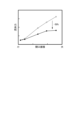
- FIG. 8 is a graph showing changes in fluid force with respect to the opening area of the outlet port.
- White circles in the figure indicate values obtained by the configuration of the comparative example described above, and black circles in the figure indicate values obtained by the configuration of this embodiment. These values were obtained by numerical analysis using CFD.
- the fluid force generated by the configuration of this embodiment is lower than the fluid force generated by the configuration of the comparative example regardless of the opening area of the outlet port. The rate of this decrease increases as the exit port opening area increases. For example, it has been found that when the exit port is fully open, the hydraulic forces are reduced by as much as 50%.
- the axial fluid force can be reduced compared to the case where the outlet port is configured with a single opening having the same opening area. That is, according to this embodiment, it is possible to suppress the influence of the fluid force on the override characteristics of the pressure control valve or the flow control valve.
- a reduction in axial fluid force is also obtained by configuring the outlet port with multiple slits. That is, it is not necessary to locally change the shape of the inner surface of the groove of the spool, such as a recess, in order to deflect the jet of the working fluid, unlike the prior art.
- minute recesses or the like are provided on the surface facing the working fluid, foreign matter in the working fluid tends to adhere to those portions. Adhesion of foreign matter interferes with the deflection of the jet.
- the present embodiment does not require such local shape changes. Therefore, the original performance of the spool valve can be maintained for a long period of time even in an environment where the working fluid is likely to be contaminated with foreign matter.
Landscapes
- Engineering & Computer Science (AREA)
- Physics & Mathematics (AREA)
- General Engineering & Computer Science (AREA)
- Fluid Mechanics (AREA)
- General Physics & Mathematics (AREA)
- Automation & Control Theory (AREA)
- Mechanical Engineering (AREA)
- Sliding Valves (AREA)
Abstract
Description
スリーブ10は軸方向ADに延伸する中空の円筒部材であり、収容穴13にスプール20を軸方向ADに移動可能に収容する。収容穴13はスリーブ10に形成され、軸2を中心として軸方向ADに延伸している。
図5は径方向RDから見た出口ポート12の幾つかの例を示す平面展開図であり、(a)は出口ポート12の第1例を示す図、(b)は出口ポート12の第2例を示す図、(c)は出口ポート12の第3例を示す図である。これらの図に示すように、出口ポート12は、複数のスリット(スロット、開口部)16を含む。複数のスリット16は、周方向CDに間隔を置きながら配置され、互いに平行に軸方向ADに延伸する。また、複数のスリット16は、軸2を含み径方向RDに延びる一平面と平行である(図4(b)参照)。隣接する2本のスリット16、16はその間のリブ19によって仕切られている。周方向CDにおけるスリット16とリブ19のそれぞれの幅は互いに等しくてもよく、異なっていてもよい。また、複数のスリット16の幅は一定でも、互いに異なっていてもよい。これは複数のリブ19の幅についても同様である。
スプール20は、基端部20aから先端部20bまで軸方向ADに延伸する断面円形の棒状部材である。図1に示すように、スプール20は、スリーブ10に形成された収容穴13内に、軸方向ADに移動可能(往復可能)に収容される。
付勢装置30は、スプール20の基端部20aを先端部20bに向けて(即ち、弁の閉方向に向けて)付勢する。図2に示すように、付勢装置30は、付勢部材としてのばね31と、一対のリテーナ32、32と、操作部(ハンドル)33とを有する。ばね31はスプール20の基端部20aをスプールの先端部20bに向けて押圧する。ばね31は所謂圧縮コイルばねであり、所定の範囲の付勢力を生じるばね係数を有する。ばね31は、一対のリテーナ32、32によって軸方向ADの両側から保持された状態で、操作部33に収容される。
本実施形態に係るスプール弁1の、圧力制御弁又は流量制御弁としての動作は、スプールを備える従来の圧力制御弁又は流量制御弁の動作と基本的に同一である。即ち、付勢装置30によるスプール20への圧力と検圧ポート56内の作動流体の圧力の差に応じてスプール20の位置が定まり、この位置に応じて出口ポートの開口面積(開度)が定まる。
Claims (4)
- 作動流体の入口ポート及び出口ポートを含み、軸方向に延伸するスリーブと、
前記スリーブ内に、前記軸方向に移動可能に収容されるスプールと、
前記スプールの基端部を当該スプールの先端部に向けて押圧する付勢部材を含む付勢装置と、
前記スプールの前記先端部に向けて開口する前記作動流体の検圧ポートと
を備え、
前記出口ポートは複数のスリットを含み、
前記複数のスリットは、前記スリーブの周方向に間隔を置きながら配置され、前記軸方向に延伸している
スプール弁。 - 前記出口ポートは、当該出口ポートの外形を規定すると共に前記周方向に間隔を置いて並んだ複数の領域に形成されている、
請求項1に記載のスプール弁。 - 前記出口ポートは、第1部分と、前記第1部分よりも前記入口ポートから離れた位置に位置する第2部分に分けられ、
前記スリーブの前記周方向に沿った前記第1部分の幅は、前記第2部分に近づくに従って増加し、
前記スリーブの前記周方向に沿った前記第2部分の幅は一定である、
請求項2に記載のスプール弁。 - 前記複数のスリットは、前記周方向に所定の間隔を置きながら、前記周方向の全域に形成されている、
請求項1に記載のスプール弁。
Priority Applications (3)
| Application Number | Priority Date | Filing Date | Title |
|---|---|---|---|
| JP2023548451A JPWO2023042775A1 (ja) | 2021-09-17 | 2022-09-12 | |
| EP22869922.9A EP4390189A1 (en) | 2021-09-17 | 2022-09-12 | Spool valve |
| US18/404,065 US20240143001A1 (en) | 2021-09-17 | 2024-01-04 | Spool valve |
Applications Claiming Priority (2)
| Application Number | Priority Date | Filing Date | Title |
|---|---|---|---|
| JP2021152171 | 2021-09-17 | ||
| JP2021-152171 | 2021-09-17 |
Related Child Applications (1)
| Application Number | Title | Priority Date | Filing Date |
|---|---|---|---|
| US18/404,065 Continuation US20240143001A1 (en) | 2021-09-17 | 2024-01-04 | Spool valve |
Publications (1)
| Publication Number | Publication Date |
|---|---|
| WO2023042775A1 true WO2023042775A1 (ja) | 2023-03-23 |
Family
ID=85602862
Family Applications (1)
| Application Number | Title | Priority Date | Filing Date |
|---|---|---|---|
| PCT/JP2022/033990 WO2023042775A1 (ja) | 2021-09-17 | 2022-09-12 | スプール弁 |
Country Status (4)
| Country | Link |
|---|---|
| US (1) | US20240143001A1 (ja) |
| EP (1) | EP4390189A1 (ja) |
| JP (1) | JPWO2023042775A1 (ja) |
| WO (1) | WO2023042775A1 (ja) |
Citations (4)
| Publication number | Priority date | Publication date | Assignee | Title |
|---|---|---|---|---|
| JPS50150832U (ja) * | 1974-05-31 | 1975-12-15 | ||
| JPH03374U (ja) * | 1989-05-25 | 1991-01-07 | ||
| JP2007315605A (ja) * | 2002-09-30 | 2007-12-06 | Jtekt Corp | 電磁弁 |
| JP2015169212A (ja) | 2014-03-04 | 2015-09-28 | 株式会社デンソー | 流体制御弁 |
-
2022
- 2022-09-12 WO PCT/JP2022/033990 patent/WO2023042775A1/ja active Application Filing
- 2022-09-12 EP EP22869922.9A patent/EP4390189A1/en active Pending
- 2022-09-12 JP JP2023548451A patent/JPWO2023042775A1/ja active Pending
-
2024
- 2024-01-04 US US18/404,065 patent/US20240143001A1/en active Pending
Patent Citations (4)
| Publication number | Priority date | Publication date | Assignee | Title |
|---|---|---|---|---|
| JPS50150832U (ja) * | 1974-05-31 | 1975-12-15 | ||
| JPH03374U (ja) * | 1989-05-25 | 1991-01-07 | ||
| JP2007315605A (ja) * | 2002-09-30 | 2007-12-06 | Jtekt Corp | 電磁弁 |
| JP2015169212A (ja) | 2014-03-04 | 2015-09-28 | 株式会社デンソー | 流体制御弁 |
Also Published As
| Publication number | Publication date |
|---|---|
| JPWO2023042775A1 (ja) | 2023-03-23 |
| EP4390189A1 (en) | 2024-06-26 |
| US20240143001A1 (en) | 2024-05-02 |
Similar Documents
| Publication | Publication Date | Title |
|---|---|---|
| US5901749A (en) | Three-way poppet valve | |
| EP2307772B1 (en) | Axial drag valve with internal sleeve actuator | |
| US10309544B2 (en) | Valve assembly | |
| US6457697B1 (en) | Foreign particle resistant valve | |
| US5199769A (en) | Valve, in particular for slip-controlled hydraulic brake systems | |
| US20230151897A1 (en) | Fuel nozzle with reduced flow tolerance | |
| CS270418B2 (en) | Pressure limiting valve for hydraulic outfit of face | |
| JP5856917B2 (ja) | 減圧弁 | |
| JP3441289B2 (ja) | 油圧回路用弁構造 | |
| WO2023042775A1 (ja) | スプール弁 | |
| WO2023042776A1 (ja) | スプール弁 | |
| US10794499B2 (en) | Servo valve housing | |
| US12048889B2 (en) | Filter assembly for a servovalve | |
| US4825903A (en) | Pressure control valve | |
| US8251097B2 (en) | Sliding valve | |
| JP7165042B2 (ja) | メカニカルシール及びその使用方法 | |
| CN111836989B (zh) | 逆止阀 | |
| EP3985231B1 (en) | Dual windage blocker and retention feature design for seal assembly | |
| EP3284931B1 (en) | Pressure regulating valve with flow anti-rotation | |
| JP2005144439A (ja) | 流体フィルタ用弁およびばね | |
| EP0628460B1 (en) | Changeover valve and flow control valve assembly having the same | |
| KR100285080B1 (ko) | 유압장치 | |
| JP3150012B2 (ja) | スプール弁 | |
| US4186909A (en) | Fail-to-neutral module | |
| JP4805711B2 (ja) | 弁装置およびそれを備える整圧器 |
Legal Events
| Date | Code | Title | Description |
|---|---|---|---|
| 121 | Ep: the epo has been informed by wipo that ep was designated in this application |
Ref document number: 22869922 Country of ref document: EP Kind code of ref document: A1 |
|
| WWE | Wipo information: entry into national phase |
Ref document number: 2023548451 Country of ref document: JP |
|
| WWE | Wipo information: entry into national phase |
Ref document number: 22869922 Country of ref document: EP Ref document number: 2022869922 Country of ref document: EP |
|
| ENP | Entry into the national phase |
Ref document number: 2022869922 Country of ref document: EP Effective date: 20240323 |
|
| NENP | Non-entry into the national phase |
Ref country code: DE |