EP3412146A2 - Aquaponic system - Google Patents
Aquaponic system Download PDFInfo
- Publication number
- EP3412146A2 EP3412146A2 EP18157774.3A EP18157774A EP3412146A2 EP 3412146 A2 EP3412146 A2 EP 3412146A2 EP 18157774 A EP18157774 A EP 18157774A EP 3412146 A2 EP3412146 A2 EP 3412146A2
- Authority
- EP
- European Patent Office
- Prior art keywords
- tanks
- water
- inlet
- cultivating
- outlet
- Prior art date
- Legal status (The legal status is an assumption and is not a legal conclusion. Google has not performed a legal analysis and makes no representation as to the accuracy of the status listed.)
- Granted
Links
Images


Classifications
-
- A—HUMAN NECESSITIES
- A01—AGRICULTURE; FORESTRY; ANIMAL HUSBANDRY; HUNTING; TRAPPING; FISHING
- A01G—HORTICULTURE; CULTIVATION OF VEGETABLES, FLOWERS, RICE, FRUIT, VINES, HOPS OR SEAWEED; FORESTRY; WATERING
- A01G31/00—Soilless cultivation, e.g. hydroponics
- A01G31/02—Special apparatus therefor
-
- A—HUMAN NECESSITIES
- A01—AGRICULTURE; FORESTRY; ANIMAL HUSBANDRY; HUNTING; TRAPPING; FISHING
- A01K—ANIMAL HUSBANDRY; CARE OF BIRDS, FISHES, INSECTS; FISHING; REARING OR BREEDING ANIMALS, NOT OTHERWISE PROVIDED FOR; NEW BREEDS OF ANIMALS
- A01K63/00—Receptacles for live fish, e.g. aquaria; Terraria
- A01K63/003—Aquaria; Terraria
-
- A—HUMAN NECESSITIES
- A01—AGRICULTURE; FORESTRY; ANIMAL HUSBANDRY; HUNTING; TRAPPING; FISHING
- A01G—HORTICULTURE; CULTIVATION OF VEGETABLES, FLOWERS, RICE, FRUIT, VINES, HOPS OR SEAWEED; FORESTRY; WATERING
- A01G31/00—Soilless cultivation, e.g. hydroponics
- A01G31/02—Special apparatus therefor
- A01G31/06—Hydroponic culture on racks or in stacked containers
-
- A—HUMAN NECESSITIES
- A01—AGRICULTURE; FORESTRY; ANIMAL HUSBANDRY; HUNTING; TRAPPING; FISHING
- A01K—ANIMAL HUSBANDRY; CARE OF BIRDS, FISHES, INSECTS; FISHING; REARING OR BREEDING ANIMALS, NOT OTHERWISE PROVIDED FOR; NEW BREEDS OF ANIMALS
- A01K63/00—Receptacles for live fish, e.g. aquaria; Terraria
- A01K63/04—Arrangements for treating water specially adapted to receptacles for live fish
- A01K63/045—Filters for aquaria
-
- C—CHEMISTRY; METALLURGY
- C02—TREATMENT OF WATER, WASTE WATER, SEWAGE, OR SLUDGE
- C02F—TREATMENT OF WATER, WASTE WATER, SEWAGE, OR SLUDGE
- C02F3/00—Biological treatment of water, waste water, or sewage
- C02F3/32—Biological treatment of water, waste water, or sewage characterised by the animals or plants used, e.g. algae
- C02F3/327—Biological treatment of water, waste water, or sewage characterised by the animals or plants used, e.g. algae characterised by animals and plants
-
- C—CHEMISTRY; METALLURGY
- C05—FERTILISERS; MANUFACTURE THEREOF
- C05F—ORGANIC FERTILISERS NOT COVERED BY SUBCLASSES C05B, C05C, e.g. FERTILISERS FROM WASTE OR REFUSE
- C05F3/00—Fertilisers from human or animal excrements, e.g. manure
-
- A—HUMAN NECESSITIES
- A01—AGRICULTURE; FORESTRY; ANIMAL HUSBANDRY; HUNTING; TRAPPING; FISHING
- A01G—HORTICULTURE; CULTIVATION OF VEGETABLES, FLOWERS, RICE, FRUIT, VINES, HOPS OR SEAWEED; FORESTRY; WATERING
- A01G31/00—Soilless cultivation, e.g. hydroponics
-
- C—CHEMISTRY; METALLURGY
- C02—TREATMENT OF WATER, WASTE WATER, SEWAGE, OR SLUDGE
- C02F—TREATMENT OF WATER, WASTE WATER, SEWAGE, OR SLUDGE
- C02F1/00—Treatment of water, waste water, or sewage
- C02F1/001—Processes for the treatment of water whereby the filtration technique is of importance
-
- C—CHEMISTRY; METALLURGY
- C02—TREATMENT OF WATER, WASTE WATER, SEWAGE, OR SLUDGE
- C02F—TREATMENT OF WATER, WASTE WATER, SEWAGE, OR SLUDGE
- C02F2103/00—Nature of the water, waste water, sewage or sludge to be treated
- C02F2103/20—Nature of the water, waste water, sewage or sludge to be treated from animal husbandry
-
- Y—GENERAL TAGGING OF NEW TECHNOLOGICAL DEVELOPMENTS; GENERAL TAGGING OF CROSS-SECTIONAL TECHNOLOGIES SPANNING OVER SEVERAL SECTIONS OF THE IPC; TECHNICAL SUBJECTS COVERED BY FORMER USPC CROSS-REFERENCE ART COLLECTIONS [XRACs] AND DIGESTS
- Y02—TECHNOLOGIES OR APPLICATIONS FOR MITIGATION OR ADAPTATION AGAINST CLIMATE CHANGE
- Y02A—TECHNOLOGIES FOR ADAPTATION TO CLIMATE CHANGE
- Y02A40/00—Adaptation technologies in agriculture, forestry, livestock or agroalimentary production
- Y02A40/10—Adaptation technologies in agriculture, forestry, livestock or agroalimentary production in agriculture
- Y02A40/20—Fertilizers of biological origin, e.g. guano or fertilizers made from animal corpses
-
- Y—GENERAL TAGGING OF NEW TECHNOLOGICAL DEVELOPMENTS; GENERAL TAGGING OF CROSS-SECTIONAL TECHNOLOGIES SPANNING OVER SEVERAL SECTIONS OF THE IPC; TECHNICAL SUBJECTS COVERED BY FORMER USPC CROSS-REFERENCE ART COLLECTIONS [XRACs] AND DIGESTS
- Y02—TECHNOLOGIES OR APPLICATIONS FOR MITIGATION OR ADAPTATION AGAINST CLIMATE CHANGE
- Y02P—CLIMATE CHANGE MITIGATION TECHNOLOGIES IN THE PRODUCTION OR PROCESSING OF GOODS
- Y02P20/00—Technologies relating to chemical industry
- Y02P20/141—Feedstock
- Y02P20/145—Feedstock the feedstock being materials of biological origin
-
- Y—GENERAL TAGGING OF NEW TECHNOLOGICAL DEVELOPMENTS; GENERAL TAGGING OF CROSS-SECTIONAL TECHNOLOGIES SPANNING OVER SEVERAL SECTIONS OF THE IPC; TECHNICAL SUBJECTS COVERED BY FORMER USPC CROSS-REFERENCE ART COLLECTIONS [XRACs] AND DIGESTS
- Y02—TECHNOLOGIES OR APPLICATIONS FOR MITIGATION OR ADAPTATION AGAINST CLIMATE CHANGE
- Y02P—CLIMATE CHANGE MITIGATION TECHNOLOGIES IN THE PRODUCTION OR PROCESSING OF GOODS
- Y02P60/00—Technologies relating to agriculture, livestock or agroalimentary industries
- Y02P60/20—Reduction of greenhouse gas [GHG] emissions in agriculture, e.g. CO2
- Y02P60/21—Dinitrogen oxide [N2O], e.g. using aquaponics, hydroponics or efficiency measures
-
- Y—GENERAL TAGGING OF NEW TECHNOLOGICAL DEVELOPMENTS; GENERAL TAGGING OF CROSS-SECTIONAL TECHNOLOGIES SPANNING OVER SEVERAL SECTIONS OF THE IPC; TECHNICAL SUBJECTS COVERED BY FORMER USPC CROSS-REFERENCE ART COLLECTIONS [XRACs] AND DIGESTS
- Y02—TECHNOLOGIES OR APPLICATIONS FOR MITIGATION OR ADAPTATION AGAINST CLIMATE CHANGE
- Y02W—CLIMATE CHANGE MITIGATION TECHNOLOGIES RELATED TO WASTEWATER TREATMENT OR WASTE MANAGEMENT
- Y02W10/00—Technologies for wastewater treatment
- Y02W10/10—Biological treatment of water, waste water, or sewage
Definitions
- the present invention relates to a fish and plant symbiotic system and, more particularly, to an aquaponic system that combines the aquaculture and the hydroponics.
- a conventional aquaponic system comprises a frame, an aquarium mounted on the frame, and a plurality of cultivating tanks arranged on the frame.
- the aquarium is provided with a pump to pump the water and the fish excrement in the aquarium to the cultivating tanks.
- Each of the cultivating tanks is provided with a siphon to deliver the water in each of the cultivating tanks to the aquarium.
- the fish excrement and feedstuff remains of the aquarium are not fermented so that the plant cannot directly absorb the nutrient of the fish excrement and feedstuff remains.
- the root of the plant easily blocks the water flow path in each of the cultivating tanks, so that the fish excrement and feedstuff remains cannot flow with the water smoothly and are easily jammed with the root of the plant, and the root of the plant will becomes black and cannot grow healthily.
- the height of the siphon cannot be adjusted when overflow happens, so that the siphon cannot correspond to different water levels required by different roots of the plant.
- the siphon needs to connect a bent tube to produce a vacuum pulling force, thereby wasting the material and space.
- the size of the frame is fixed and cannot be adjusted according to the practical requirement, so that the conventional aquaponic system is not available for places of different sizes.
- an aquaponic system comprising a frame, an aquarium located at a lower portion of the frame and having an interior provided with a motor, a plurality of cultivating tanks arranged on the frame and having two opposite sides provided with a plurality of inlet tanks and a plurality of outlet tanks, and a strainer unit mounted on the frame.
- Each of the inlet tanks is provided with a water inlet seat.
- the water inlet seat of the uppermost one of the inlet tanks is connected with a water inlet pipe.
- Each of the outlet tanks is connected with a lower one of the inlet tanks.
- Each of the outlet tanks is provided with a water outlet seat which is provided with a water outlet tube.
- the water outlet tube of the lowermost one of the outlet tanks is connected to the aquarium.
- the strainer unit includes a water outlet port connected with the water inlet pipe, a water inlet port connected with a water feeding pipe which is connected with the motor of the aquarium, two hollow clamping plates located between the water outlet port and the water inlet port, a filtering sponge clamped between the two clamping plates, a fertilizer ferment chamber located under the water inlet port, and a drain pipe connected with the fertilizer ferment chamber.
- the water inlet port is located at a position lower than that of the water outlet port.
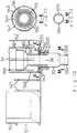
- an aquaponic system in accordance with the preferred embodiment of the present invention comprises an aquarium 10, a frame 20, a plurality of cultivating tanks 30, a plurality of inlet tanks 40, a plurality of outlet tanks 50, a strainer unit 60 and a plurality of illuminating devices 70.
- the aquarium 10 is located at a lower portion of the frame 20 and has an interior provided with a motor 11 (see FIG. 16 ).
- the frame 20 includes a plurality of connectors 21, a plurality of upright tubes 22, a plurality of transverse tubes 23, a plurality of adjusting tubes 24, a plurality of stands 25, a plurality of hanging brackets 26, a plurality of pins 27 and a plurality of fasteners 28.
- Each of the connectors 21 is hollow and allows insertion of two of the upright tubes 22.
- Each of the connectors 21 is provided with two mounting sleeves 29 allowing insertion of two of the transverse tubes 23.
- the two mounting sleeves 29 are perpendicular to each other.
- the lowermost one of the connectors 21 has a lower end connected with one of the adjusting tubes 24.
- Each of the adjusting tubes 24 has a lower end provided with an external thread 241.
- Each of the stands 25 has an upper end provided with an internal thread 251 screwed onto the external thread 241 of one of the adjusting tubes 24, so that each of the stands 25 is moved relative to one of the adjusting tubes 24 by rotation to adjust the distance between each of the stands 25 and one of the adjusting tubes 24.
- the uppermost one of the connectors 21 has an upper end connected with one of the hanging brackets 26.
- Each of the connectors 21, each of the mounting sleeves 29, each of the upright tubes 22, each of the transverse tubes 23 and each of the adjusting tubes 24 is provided with an aperture 211, 291, 221, 231 and 242 allowing insertion of the pins 27 and fastened by the fasteners 28.
- Each of the pins 27 is provided with an annular groove 271.
- Each of the fasteners 28 is provided with a C-shaped snap ring 281 retained in the annular groove 271 of one of the pins 27.
- the cultivating tanks 30 are arranged on the frame 20 to grow the plant.
- Each of the cultivating tanks 30 has a bottom provided with an arcuate separation board 34 to separate and prevent the root of the plant from blocking the water flow path 342 (see FIG. 18 ).
- the arcuate separation board 34 has two sides provided with a plurality of connecting holes 341 which are arranged in a corrugated manner to allow circulation of the water so that the water freely flows forward and backward, upward and downward, and leftward and rightward.
- Each of the cultivating tanks 30 has a first end provided with a hollow external thread 35 and a second end provided with a through hole 36.
- the hollow external thread 35 of one of the cultivating tanks 30 extends through the through hole 36 of another one of the cultivating tanks 30, and a nut 37 is screwed onto the hollow external thread 35, so that the cultivating tanks 30 are connected serially.
- the inlet tanks 40 and the outlet tanks 50 are located at two opposite sides of the cultivating tanks 30 and are arranged in an alternating manner as shown in FIG. 1 .
- a plurality of inverted U-shaped securing plates 38 are located between the cultivating tanks 30, the inlet tanks 40 and the outlet tanks 50 to connect and secure the cultivating tanks 30, the inlet tanks 40 and the outlet tanks 50 as shown in FIGS. 4 and 21 .
- the inlet tanks 40 are arranged on the left side of odd layers of the cultivating tanks 30 and the right side of even layers of the cultivating tanks 30 as shown in FIG. 1 .
- Each of the inlet tanks 40 is provided with a plurality of hollow external threads 41 each of which extends through the through hole 36 of one of the cultivating tanks 30, and a nut 37 is screwed onto the hollow external thread 41, so that the cultivating tanks 30 and the inlet tanks 40 are combined together.
- each of the inlet tanks 40 is provided with a water inlet seat 42 having a water intake port 43.
- the water intake port 43 of the uppermost one of the inlet tanks 40 is connected with a water inlet pipe 44.
- the outlet tanks 50 are arranged on the right side of odd layers of the cultivating tanks 30 and the left side of even layers of the cultivating tanks 30 as shown in FIG. 1 .
- Each of the outlet tanks 50 is provided with a plurality of through holes 51, the hollow external thread 35 of each of the cultivating tanks 30 extends through one of the through holes 51 of one of the cultivating tanks 30, and a nut 37 is screwed onto the hollow external thread 35, so that the cultivating tanks 30 and the outlet tanks 50 are combined together.
- a plurality of caps 31 are mounted on the cultivating tanks 30, the inlet tanks 40 and the outlet tanks 50.
- Each of the caps 31 is provided with a plurality of large holes 32 for mounting larger plant baskets 1 (see FIG. 21 ) and a plurality of small holes 33 for mounting smaller plant baskets 2 (see FIG. 22 ).
- each of the outlet tanks 50 is provided with a water outlet seat 52 which is provided with two retaining groves 521, two hollow clamping plates 53 (see FIG. 7 ) are mounted in the two retaining groves 521 as shown in FIG. 14 , and a filtering sponge "A" (see FIG. 7 ) is clamped between the two clamping plates 53.
- the water outlet seat 52 of each of the outlet tanks 50 has a bottom provided with a water outlet hole 522, and a housing 54 is received in the water outlet seat 52 and located above the water outlet hole 522.
- the housing 54 has a bottom provided with a plurality of passages 541 allowing entrance of the water and a plurality of wings 542 arranged between the passages 541.
- Each of the wings 542 is provided with a positioning portion 543.
- the housing 54 has a closed top face provided with a plurality of channels 544 extending through the housing 54 and connected to the passages 541, and ambient air passes through the channels 544 into the water outlet seat 52 as shown in FIG. 13 .
- a water outlet tube 55 extends through the water outlet hole 522 of each of the outlet tanks 50.
- the water outlet tube 55 is provided with an outer thread 553, and a nut "N" is screwed onto the outer thread 553 of the water outlet tube 55.
- the water outlet tube 55 has an upper end provided with an enlarged stop edge 551 abutting the positioning portion 543 of each of the wings 542 of the housing 54, and an O-ring 552 is mounted on the water outlet tube 55 and located between the stop edge 551 and the bottom of the water outlet seat 52.
- the water outlet tube 55 has a lower end provided with a reduced pipe joint 554 connected with a water drain pipe 556 which is connected with the water intake port 43 of the water inlet seat 42 of a lower one of the inlet tanks 40.
- the water drain pipe 556 of the lowermost one of the outlet tanks 50 is connected to the aquarium 10 as shown in FIG. 16 .
- the pipe joint 554 has an inner wall provided with a projection 555 that produces a vacuum pulling force to form a turbulent flow.
- the projection 555 protrudes inward and has area that is one third of a cross-sectional area of the pipe joint 554, to reduce the water outlet area of the pipe joint 554.
- a siphon 56 is mounted in the housing 54 and inserted into the water outlet tube 55.
- the siphon 56 has an upper end provided with a water entrance 561 which has an outer diameter smaller than an inner diameter of the housing 54, and a water intake space 545 (see FIG. 13 ) is defined between the water entrance 561 and the housing 54.
- the water entrance 561 has a lower end provided with a reduced conic portion 562 which has a lower end provided with a water outlet line 563 which has a periphery provided with a plurality of positioning teeth 564 engaging and positioned in an inner wall of the water outlet tube 55 by a friction between the positioning teeth 564 and the inner wall of the water outlet tube 55.
- the positioning teeth 564 are moved upward or downward in the water outlet tube 55 to adjust the position of the siphon 56.
- the housing 54 has a closed top face, and the ambient air cannot enter the water outlet seat 52 from the housing 54, so that the water will always flow downward due to the siphoning action.
- the top face of the housing 54 is provided with the channels 544, to allow the ambient air passing through the channels 544 into the water outlet seat 52, and to form a flow cut state, so that the pressure in the housing 54 is the same as that of the ambient environment, and the water will not always flow downward due to the siphoning action.
- the projection 555 reduces the water outlet area of the pipe joint 554, so that when the water flows through the projection 555, the flow rate is increased, to produce a vacuum pulling force that forms a turbulent flow as shown in FIG. 13 .
- the strainer unit 60 is mounted on the frame 20 and includes a water outlet port 61 connected with the water inlet pipe 44, two hanging cords 62 suspended on one of the hanging brackets 26 of the frame 20, a water inlet port 63 connected with a water feeding pipe 64 which is connected with the motor 11 of the aquarium 10, two hollow clamping plates 65 and 66 located between the water outlet port 61 and the water inlet port 63, a filtering sponge "A" clamped between the two clamping plates 65 and 66, a fertilizer ferment chamber 67 located under the water inlet port 63, and a drain pipe 68 connected with the fertilizer ferment chamber 67.
- the water inlet port 63 is located at a position lower than that of the water outlet port 61.
- the illuminating devices 70 are located above the cultivating tanks 30 to provide a light source for growth of the plant.
- each of the illuminating devices 70 is a light emitting diode (LED).
- the fish excrement and feedstuff remains attached to the bottom of the filtering sponge "A" are flushed by the water flow of the water feeding pipe 64 and are moved downward into the fertilizer ferment chamber 67, so that the fish excrement and feedstuff remains are fermented into a small molecular fertilizer which is lighter than the water.
- the small molecular fertilizer is pushed upward by the water flow to pass through the filtering sponge "A".
- the small molecular fertilizer is carried by the clean water to pass through the water outlet port 61, the water inlet pipe 44 and the water intake port 43 of the water inlet seat 42 into the uppermost one of the inlet tanks 40, and is then delivered into and evenly distributed to the cultivating tanks 30, so that the small molecular fertilizer provides nutrient for growth of the plant in the cultivating tanks 30.
- the water flows through the cultivating tanks 30 into the uppermost one of the outlet tanks 50.
- the filtering sponge "A" strains the impurities contained in the water.
- the clean water flows through the passages 541 of the housing 54, then flows upward through the water intake space between the water entrance 561 and the housing 54, then flows downward into the siphon 56 as shown in FIG.
- the water flows through one of the inlet tanks 40, the cultivating tanks 30 and one of the outlet tanks 50 of an upper layer and then flows through one of the inlet tanks 40, the cultivating tanks 30 and one of the outlet tanks 50 of a lower layer, so that the water in turn flows through the inlet tanks 40, the cultivating tanks 30 and the outlet tanks 50 from top to down as shown in FIG. 16 , and the small molecular fertilizer provides nutrient to the plant in the cultivating tanks 30 layer by layer.
- the filtering sponge "A" of the lowermost one of the outlet tanks 50 strains the impurities contained in the water, and the clean water flows through the water drain pipe 556 into the aquarium 10 as shown in FIG. 24 .
- the water flows through all of the cultivating tanks 30 from top to down and layer by layer in a substantially S-shaped manner as shown in FIG. 17 .
- the fish excrement and feedstuff remains of the aquarium 10 are fermented into a small molecular fertilizer that is easily absorbed by the plant so as to promote the growth of the plant.
- the arcuate separation board 34 of each of the cultivating tanks 30 separates and prevents the root of the plant from blocking the water flow path 342.
- the connecting holes 341 of the arcuate separation board 34 are arranged in a corrugated manner to allow circulation of the water, so that the fish excrement, feedstuff remains and impurities do not contact the root of the plant and will flow with the water conveniently, thereby preventing the root of the plant from being jammed or choked, such that the root of the plant absorbs the air and nutrient freely and is kept at a white color so as to grow healthily.
- the positioning teeth 564 are moved in the water outlet tube 55 to adjust the height of the siphon 56, and to control the water level when overflow happens, so as to correspond to different water levels required by different roots of the plant.
- the siphon 56 produces a vacuum pulling force without needing a bent tube, so that the water drain pipe 556 may be made into a straight pipe, thereby saving the material and space.
- the frame 20 is shortened or expanded according to the practical requirement, so that the aquaponic system is available for places of different sizes.
Abstract
Description
- The present invention relates to a fish and plant symbiotic system and, more particularly, to an aquaponic system that combines the aquaculture and the hydroponics.
- A conventional aquaponic system comprises a frame, an aquarium mounted on the frame, and a plurality of cultivating tanks arranged on the frame. The aquarium is provided with a pump to pump the water and the fish excrement in the aquarium to the cultivating tanks. Each of the cultivating tanks is provided with a siphon to deliver the water in each of the cultivating tanks to the aquarium. However, the fish excrement and feedstuff remains of the aquarium are not fermented so that the plant cannot directly absorb the nutrient of the fish excrement and feedstuff remains. In addition, the root of the plant easily blocks the water flow path in each of the cultivating tanks, so that the fish excrement and feedstuff remains cannot flow with the water smoothly and are easily jammed with the root of the plant, and the root of the plant will becomes black and cannot grow healthily. Further, the height of the siphon cannot be adjusted when overflow happens, so that the siphon cannot correspond to different water levels required by different roots of the plant. Further, the siphon needs to connect a bent tube to produce a vacuum pulling force, thereby wasting the material and space. Further, the size of the frame is fixed and cannot be adjusted according to the practical requirement, so that the conventional aquaponic system is not available for places of different sizes.
- In accordance with the present invention, there is provided an aquaponic system comprising a frame, an aquarium located at a lower portion of the frame and having an interior provided with a motor, a plurality of cultivating tanks arranged on the frame and having two opposite sides provided with a plurality of inlet tanks and a plurality of outlet tanks, and a strainer unit mounted on the frame. Each of the inlet tanks is provided with a water inlet seat. The water inlet seat of the uppermost one of the inlet tanks is connected with a water inlet pipe. Each of the outlet tanks is connected with a lower one of the inlet tanks. Each of the outlet tanks is provided with a water outlet seat which is provided with a water outlet tube. The water outlet tube of the lowermost one of the outlet tanks is connected to the aquarium. The strainer unit includes a water outlet port connected with the water inlet pipe, a water inlet port connected with a water feeding pipe which is connected with the motor of the aquarium, two hollow clamping plates located between the water outlet port and the water inlet port, a filtering sponge clamped between the two clamping plates, a fertilizer ferment chamber located under the water inlet port, and a drain pipe connected with the fertilizer ferment chamber. The water inlet port is located at a position lower than that of the water outlet port.
- Further benefits and advantages of the present invention will become apparent after a careful reading of the detailed description with appropriate reference to the accompanying drawings.
- In the drawings:
-
FIG. 1 is a perspective view of an aquaponic system in accordance with the preferred embodiment of the present invention. -
FIG. 2 is a partially exploded perspective view of a frame of the aquaponic system as shown inFIG. 1 . -
FIG. 3 is a partially exploded perspective view of the frame of the aquaponic system as shown inFIG. 1 . -
FIG. 4 is a partially perspective view of the aquaponic system as shown inFIG. 1 . -
FIG. 5 is a partially exploded perspective view of the cultivating tanks of the aquaponic system in accordance with the preferred embodiment of the present invention. -
FIG. 6 is a partially exploded perspective view of the aquaponic system as shown inFIG. 4 . -
FIG. 7 is a partially exploded perspective view of the aquaponic system as shown inFIG. 4 . -
FIG. 8 is a locally enlarged perspective view of the outlet tank of the aquaponic system as shown inFIG. 4 . -
FIG. 9 is an exploded perspective view of the outlet tank of the aquaponic system as shown inFIG. 8 , and a locally enlarged view taken along character "D". -
FIG. 10 is a cross-sectional view of the outlet tank of the aquaponic system as shown inFIG. 8 . -
FIG. 11 is a cross-sectional view of the outlet tank of the aquaponic system taken along line E-E as shown inFIG. 10 . -
FIG. 12 is a cross-sectional view of the outlet tank of the aquaponic system taken along line M-M as shown inFIG. 10 . -
FIG. 13 is a schematic operational view of the aquaponic system as shown inFIG. 10 in use. -
FIG. 14 is a schematic operational view of the aquaponic system as shown inFIG. 10 , showing adjustment of the siphon. -
FIG. 15 is an exploded perspective view of a strainer unit of the aquaponic system as shown inFIG. 1 . -
FIG. 16 is a schematic side operational view of the aquaponic system as shown inFIG. 1 in use. -
FIG. 17 is a schematic front operational view of the aquaponic system as shown inFIG. 1 in use. -
FIG. 18 is a cross-sectional view of the aquaponic system taken along line M-M as shown inFIG. 17 . -
FIG. 19 is a cross-sectional view of the aquaponic system taken along line S-S as shown inFIG. 17 . -
FIG. 20 is a cross-sectional view of the aquaponic system taken along line E-E as shown inFIG. 17 . -
FIG. 21 is a partially front view of the aquaponic system for larger plant baskets, and a locally enlarged view taken along circle "A". -
FIG. 22 is a partially front view of the aquaponic system for smaller plant baskets. -
FIG. 23 is a partially front operational view of the aquaponic system as shown inFIG. 1 in use. -
FIG. 24 is a partially front operational view of the aquaponic system as shown inFIG. 1 in use. - Referring to the drawings and initially to
FIGS. 1-17 , an aquaponic system in accordance with the preferred embodiment of the present invention comprises anaquarium 10, aframe 20, a plurality of cultivatingtanks 30, a plurality ofinlet tanks 40, a plurality ofoutlet tanks 50, astrainer unit 60 and a plurality ofilluminating devices 70. - The
aquarium 10 is located at a lower portion of theframe 20 and has an interior provided with a motor 11 (seeFIG. 16 ). - As best shown in
FIGS. 2 and3 , theframe 20 includes a plurality ofconnectors 21, a plurality ofupright tubes 22, a plurality oftransverse tubes 23, a plurality of adjustingtubes 24, a plurality ofstands 25, a plurality ofhanging brackets 26, a plurality ofpins 27 and a plurality offasteners 28. Each of theconnectors 21 is hollow and allows insertion of two of theupright tubes 22. Each of theconnectors 21 is provided with twomounting sleeves 29 allowing insertion of two of thetransverse tubes 23. The twomounting sleeves 29 are perpendicular to each other. The lowermost one of theconnectors 21 has a lower end connected with one of the adjustingtubes 24. Each of the adjustingtubes 24 has a lower end provided with anexternal thread 241. Each of thestands 25 has an upper end provided with aninternal thread 251 screwed onto theexternal thread 241 of one of the adjustingtubes 24, so that each of thestands 25 is moved relative to one of the adjustingtubes 24 by rotation to adjust the distance between each of thestands 25 and one of the adjustingtubes 24. The uppermost one of theconnectors 21 has an upper end connected with one of the hangingbrackets 26. Each of theconnectors 21, each of themounting sleeves 29, each of theupright tubes 22, each of thetransverse tubes 23 and each of the adjustingtubes 24 is provided with anaperture pins 27 and fastened by thefasteners 28. Each of thepins 27 is provided with anannular groove 271. Each of thefasteners 28 is provided with a C-shaped snap ring 281 retained in theannular groove 271 of one of thepins 27. - As best shown in
FIGS. 4-7 , the cultivatingtanks 30 are arranged on theframe 20 to grow the plant. Each of the cultivatingtanks 30 has a bottom provided with anarcuate separation board 34 to separate and prevent the root of the plant from blocking the water flow path 342 (seeFIG. 18 ). Thearcuate separation board 34 has two sides provided with a plurality of connectingholes 341 which are arranged in a corrugated manner to allow circulation of the water so that the water freely flows forward and backward, upward and downward, and leftward and rightward. Each of the cultivatingtanks 30 has a first end provided with a hollowexternal thread 35 and a second end provided with athrough hole 36. The hollowexternal thread 35 of one of the cultivatingtanks 30 extends through the throughhole 36 of another one of the cultivatingtanks 30, and anut 37 is screwed onto the hollowexternal thread 35, so that the cultivatingtanks 30 are connected serially. - The
inlet tanks 40 and theoutlet tanks 50 are located at two opposite sides of the cultivatingtanks 30 and are arranged in an alternating manner as shown inFIG. 1 . A plurality of inverted U-shapedsecuring plates 38 are located between the cultivatingtanks 30, theinlet tanks 40 and theoutlet tanks 50 to connect and secure the cultivatingtanks 30, theinlet tanks 40 and theoutlet tanks 50 as shown inFIGS. 4 and21 . - The
inlet tanks 40 are arranged on the left side of odd layers of the cultivatingtanks 30 and the right side of even layers of the cultivatingtanks 30 as shown inFIG. 1 . Each of theinlet tanks 40 is provided with a plurality of hollow external threads 41 each of which extends through the throughhole 36 of one of the cultivatingtanks 30, and anut 37 is screwed onto the hollow external thread 41, so that the cultivatingtanks 30 and theinlet tanks 40 are combined together. As best shown inFIGS. 19 and21 , each of theinlet tanks 40 is provided with awater inlet seat 42 having awater intake port 43. Thewater intake port 43 of the uppermost one of theinlet tanks 40 is connected with awater inlet pipe 44. - The
outlet tanks 50 are arranged on the right side of odd layers of the cultivatingtanks 30 and the left side of even layers of the cultivatingtanks 30 as shown inFIG. 1 . Each of theoutlet tanks 50 is provided with a plurality of throughholes 51, the hollowexternal thread 35 of each of the cultivatingtanks 30 extends through one of the throughholes 51 of one of the cultivatingtanks 30, and anut 37 is screwed onto the hollowexternal thread 35, so that the cultivatingtanks 30 and theoutlet tanks 50 are combined together. - A plurality of
caps 31 are mounted on the cultivatingtanks 30, theinlet tanks 40 and theoutlet tanks 50. Each of thecaps 31 is provided with a plurality oflarge holes 32 for mounting larger plant baskets 1 (seeFIG. 21 ) and a plurality ofsmall holes 33 for mounting smaller plant baskets 2 (seeFIG. 22 ). - As best shown in
FIGS. 7-14 , each of theoutlet tanks 50 is provided with awater outlet seat 52 which is provided with two retaininggroves 521, two hollow clamping plates 53 (seeFIG. 7 ) are mounted in the two retaininggroves 521 as shown inFIG. 14 , and a filtering sponge "A" (seeFIG. 7 ) is clamped between the two clampingplates 53. Thewater outlet seat 52 of each of theoutlet tanks 50 has a bottom provided with awater outlet hole 522, and ahousing 54 is received in thewater outlet seat 52 and located above thewater outlet hole 522. Thehousing 54 has a bottom provided with a plurality ofpassages 541 allowing entrance of the water and a plurality ofwings 542 arranged between thepassages 541. Each of thewings 542 is provided with apositioning portion 543. Thehousing 54 has a closed top face provided with a plurality ofchannels 544 extending through thehousing 54 and connected to thepassages 541, and ambient air passes through thechannels 544 into thewater outlet seat 52 as shown inFIG. 13 . Awater outlet tube 55 extends through thewater outlet hole 522 of each of theoutlet tanks 50. Thewater outlet tube 55 is provided with anouter thread 553, and a nut "N" is screwed onto theouter thread 553 of thewater outlet tube 55. Thewater outlet tube 55 has an upper end provided with anenlarged stop edge 551 abutting thepositioning portion 543 of each of thewings 542 of thehousing 54, and an O-ring 552 is mounted on thewater outlet tube 55 and located between thestop edge 551 and the bottom of thewater outlet seat 52. Thewater outlet tube 55 has a lower end provided with a reduced pipe joint 554 connected with awater drain pipe 556 which is connected with thewater intake port 43 of thewater inlet seat 42 of a lower one of theinlet tanks 40. Thewater drain pipe 556 of the lowermost one of theoutlet tanks 50 is connected to theaquarium 10 as shown inFIG. 16 . The pipe joint 554 has an inner wall provided with aprojection 555 that produces a vacuum pulling force to form a turbulent flow. Theprojection 555 protrudes inward and has area that is one third of a cross-sectional area of the pipe joint 554, to reduce the water outlet area of thepipe joint 554. A siphon 56 is mounted in thehousing 54 and inserted into thewater outlet tube 55. The siphon 56 has an upper end provided with awater entrance 561 which has an outer diameter smaller than an inner diameter of thehousing 54, and a water intake space 545 (seeFIG. 13 ) is defined between thewater entrance 561 and thehousing 54. Thewater entrance 561 has a lower end provided with a reducedconic portion 562 which has a lower end provided with awater outlet line 563 which has a periphery provided with a plurality ofpositioning teeth 564 engaging and positioned in an inner wall of thewater outlet tube 55 by a friction between the positioningteeth 564 and the inner wall of thewater outlet tube 55. The positioningteeth 564 are moved upward or downward in thewater outlet tube 55 to adjust the position of the siphon 56. - It is appreciated that, the
housing 54 has a closed top face, and the ambient air cannot enter thewater outlet seat 52 from thehousing 54, so that the water will always flow downward due to the siphoning action. Thus, the top face of thehousing 54 is provided with thechannels 544, to allow the ambient air passing through thechannels 544 into thewater outlet seat 52, and to form a flow cut state, so that the pressure in thehousing 54 is the same as that of the ambient environment, and the water will not always flow downward due to the siphoning action. In addition, theprojection 555 reduces the water outlet area of the pipe joint 554, so that when the water flows through theprojection 555, the flow rate is increased, to produce a vacuum pulling force that forms a turbulent flow as shown inFIG. 13 . - As best shown in
FIGS. 15 and16 , thestrainer unit 60 is mounted on theframe 20 and includes awater outlet port 61 connected with thewater inlet pipe 44, two hangingcords 62 suspended on one of the hangingbrackets 26 of theframe 20, awater inlet port 63 connected with awater feeding pipe 64 which is connected with the motor 11 of theaquarium 10, twohollow clamping plates water outlet port 61 and thewater inlet port 63, a filtering sponge "A" clamped between the two clampingplates fertilizer ferment chamber 67 located under thewater inlet port 63, and adrain pipe 68 connected with thefertilizer ferment chamber 67. Thewater inlet port 63 is located at a position lower than that of thewater outlet port 61. - As best shown in
FIG. 17 , the illuminatingdevices 70 are located above the cultivatingtanks 30 to provide a light source for growth of the plant. Preferably, each of the illuminatingdevices 70 is a light emitting diode (LED). - In operation, referring to
FIGS. 16-24 with reference toFIGS. 1-15 , when the dirty water of theaquarium 10 is extracted by the motor 11 and delivered through thewater feeding pipe 64 into thestrainer unit 60, the dirty water flows upward to pass through the filtering sponge "A" as shown inFIG. 19 . At this time, the filtering sponge "A" strains the fish excrement, feedstuff remains and impurities contained in the dirty water, and the filtered water passes through the filtering sponge "A", thewater outlet port 61, thewater inlet pipe 44 and thewater intake port 43 of thewater inlet seat 42 into the uppermost one of theinlet tanks 40, and is delivered into the cultivatingtanks 30. At the same time, the fish excrement and feedstuff remains attached to the bottom of the filtering sponge "A" are flushed by the water flow of thewater feeding pipe 64 and are moved downward into thefertilizer ferment chamber 67, so that the fish excrement and feedstuff remains are fermented into a small molecular fertilizer which is lighter than the water. In such a manner, the small molecular fertilizer is pushed upward by the water flow to pass through the filtering sponge "A". Then, the small molecular fertilizer is carried by the clean water to pass through thewater outlet port 61, thewater inlet pipe 44 and thewater intake port 43 of thewater inlet seat 42 into the uppermost one of theinlet tanks 40, and is then delivered into and evenly distributed to the cultivatingtanks 30, so that the small molecular fertilizer provides nutrient for growth of the plant in the cultivatingtanks 30. Then, the water flows through the cultivatingtanks 30 into the uppermost one of theoutlet tanks 50. At this time, the filtering sponge "A" strains the impurities contained in the water. Then, the clean water flows through thepassages 541 of thehousing 54, then flows upward through the water intake space between thewater entrance 561 and thehousing 54, then flows downward into the siphon 56 as shown inFIG. 23 , then flows through thewater outlet tube 55 and thewater drain pipe 556, and then flows through thewater intake port 43 of thewater inlet seat 42 into a lower one of theinlet tanks 40. In such a manner, the water flows through one of theinlet tanks 40, the cultivatingtanks 30 and one of theoutlet tanks 50 of an upper layer and then flows through one of theinlet tanks 40, the cultivatingtanks 30 and one of theoutlet tanks 50 of a lower layer, so that the water in turn flows through theinlet tanks 40, the cultivatingtanks 30 and theoutlet tanks 50 from top to down as shown inFIG. 16 , and the small molecular fertilizer provides nutrient to the plant in the cultivatingtanks 30 layer by layer. Finally, the filtering sponge "A" of the lowermost one of theoutlet tanks 50 strains the impurities contained in the water, and the clean water flows through thewater drain pipe 556 into theaquarium 10 as shown inFIG. 24 . Thus, the water flows through all of the cultivatingtanks 30 from top to down and layer by layer in a substantially S-shaped manner as shown inFIG. 17 . - Accordingly, the fish excrement and feedstuff remains of the
aquarium 10 are fermented into a small molecular fertilizer that is easily absorbed by the plant so as to promote the growth of the plant. In addition, thearcuate separation board 34 of each of the cultivatingtanks 30 separates and prevents the root of the plant from blocking the water flow path 342. Further, the connectingholes 341 of thearcuate separation board 34 are arranged in a corrugated manner to allow circulation of the water, so that the fish excrement, feedstuff remains and impurities do not contact the root of the plant and will flow with the water conveniently, thereby preventing the root of the plant from being jammed or choked, such that the root of the plant absorbs the air and nutrient freely and is kept at a white color so as to grow healthily. Further, the positioningteeth 564 are moved in thewater outlet tube 55 to adjust the height of the siphon 56, and to control the water level when overflow happens, so as to correspond to different water levels required by different roots of the plant. Further, the siphon 56 produces a vacuum pulling force without needing a bent tube, so that thewater drain pipe 556 may be made into a straight pipe, thereby saving the material and space. Further, theframe 20 is shortened or expanded according to the practical requirement, so that the aquaponic system is available for places of different sizes. - Although the invention has been explained in relation to its preferred embodiment(s) as mentioned above, it is to be understood that many other possible modifications and variations can be made without departing from the scope of the present invention. It is, therefore, contemplated that the appended claim or claims will cover such modifications and variations that fall within the scope of the invention.
Claims (10)
- An aquaponic system comprising:a frame (20);an aquarium (10) located at a lower portion of the frame and having an interior provided with a motor (11);a plurality of cultivating tanks (30) arranged on the frame and having two opposite sides provided with a plurality of inlet tanks (40) and a plurality of outlet tanks (50); anda strainer unit (60) mounted on the frame;wherein:each of the inlet tanks is provided with a water inlet seat (42);the water inlet seat of the uppermost one of the inlet tanks is connected with a water inlet pipe (44);each of the outlet tanks is connected with a lower one of the inlet tanks;each of the outlet tanks is provided with a water outlet seat (52) which is provided with a water outlet tube (55);the water outlet tube of the lowermost one of the outlet tanks is connected to the aquarium;the strainer unit includes:a water outlet port (61) connected with the water inlet pipe;a water inlet port (63) connected with a water feeding pipe (64) which is connected with the motor of the aquarium;two hollow clamping plates (65, 66) located between the water outlet port and the water inlet port;a filtering sponge (A) clamped between the two clamping plates;a fertilizer ferment chamber (67) located under the water inlet port; anda drain pipe (68) connected with the fertilizer ferment chamber; andthe water inlet port is located at a position lower than that of the water outlet port.
- An aquaponic system comprising:a frame;an aquarium located at a lower portion of the frame and having an interior provided with a motor; anda plurality of cultivating tanks arranged on the frame and having two opposite sides provided with a plurality of inlet tanks and a plurality of outlet tanks;wherein:each of the outlet tanks is connected with a lower one of the inlet tanks;each of the cultivating tanks has a first end provided with a hollow external thread (35) and a second end provided with a through hole (36);the hollow external thread of one of the cultivating tanks extends through the through hole of another one of the cultivating tanks, and a nut (37) is screwed onto the hollow external thread, so that the cultivating tanks are connected serially;each of the inlet tanks is provided with a plurality of hollow external threads (41) each of which extends through the through hole of one of the cultivating tanks, and a nut is screwed onto the hollow external thread, so that the cultivating tanks and the inlet tanks are combined together;each of the outlet tanks is provided with a plurality of through holes (51), the hollow external thread of each of the cultivating tanks extends through one of the through holes of one of the cultivating tanks, and a nut is screwed onto the hollow external thread, so that the cultivating tanks and the outlet tanks are combined together;a plurality of caps (31) are mounted on the cultivating tanks, the inlet tanks and the outlet tanks; andeach of the caps is provided with a plurality of large holes (32) and a plurality of small holes (33).
- An aquaponic system comprising:a frame;an aquarium located at a lower portion of the frame and having an interior provided with a motor; anda plurality of cultivating tanks arranged on the frame and having two opposite sides provided with a plurality of inlet tanks and a plurality of outlet tanks;wherein:each of the outlet tanks is connected with a lower one of the inlet tanks;each of the cultivating tanks has a bottom provided with an arcuate separation board (34); andthe arcuate separation board has two sides provided with a plurality of connecting holes (341) which are arranged in a corrugated manner.
- The aquaponic system of claim 1, wherein:the frame includes a plurality of connectors (21), a plurality of upright tubes (22), a plurality of transverse tubes (23), a plurality of adjusting tubes (24), a plurality of stands (25), a plurality of pins (27) and a plurality of fasteners (28);each of the connectors allows insertion of two of the upright tubes;each of the connectors is provided with two mounting sleeves (29) allowing insertion of two of the transverse tubes;the lowermost one of the connectors has a lower end connected with one of the adjusting tubes;each of the adjusting tubes has a lower end provided with an external thread (241);each of the stands has an upper end provided with an internal thread (251) screwed onto the external thread of one of the adjusting tubes;each of the connectors, each of the mounting sleeves, each of the upright tubes, each of the transverse tubes and each of the adjusting tubes is provided with an aperture (211, 291, 221, 231, 242) allowing insertion of the pins and fastened by the fasteners;each of the pins is provided with an annular groove (271); andeach of the fasteners is provided with a C-shaped snap ring (281) retained in the annular groove of one of the pins.
- The aquaponic system of claim 1, wherein a plurality of inverted U-shaped securing plates (38) are located between the cultivating tanks, the inlet tanks and the outlet tanks to connect and secure the cultivating tanks, the inlet tanks and the outlet tanks.
- The aquaponic system of claim 1, wherein:the water inlet seat of each of the inlet tanks has a water intake port (43);the water intake port of the uppermost one of the inlet tanks is connected with the water inlet pipe; andthe water outlet tube of each of the outlet tanks is connected to the water intake port of the water inlet seat of a lower one of the inlet tanks.
- The aquaponic system of claim 1, wherein:each of the cultivating tanks has a first end provided with a hollow external thread (35) and a second end provided with a through hole (36);the hollow external thread of one of the cultivating tanks extends through the through hole of another one of the cultivating tanks, and a nut (37) is screwed onto the hollow external thread, so that the cultivating tanks are connected serially;each of the inlet tanks is provided with a plurality of hollow external threads each of which extends through the through hole of one of the cultivating tanks, and a nut is screwed onto the hollow external thread, so that the cultivating tanks and the inlet tanks are combined together; andeach of the outlet tanks is provided with a plurality of through holes, the hollow external thread of each of the cultivating tanks extends through one of the through holes of one of the cultivating tanks, and a nut is screwed onto the hollow external thread, so that the cultivating tanks and the outlet tanks are combined together.
- The aquaponic system of claim 1, wherein the frame includes a plurality of hanging brackets (26).
- The aquaponic system of claim 1, further comprising:a plurality of illuminating devices (70) located above the cultivating tanks.
- The aquaponic system of claim 1, wherein:two hollow clamping plates are mounted in the water outlet seat of each of the outlet tanks, and a filtering sponge (A) is clamped between the two clamping plates;the water outlet seat of each of the outlet tanks has a bottom provided with a water outlet hole (522), and a housing (54) is received in the water outlet seat and located above the water outlet hole;the housing has a bottom provided with a plurality of passages (541) and a plurality of wings (542) arranged between the passages;the housing has a closed top face provided with a plurality of channels (544) extending through the housing and connected to the passages, and ambient air passes through the channels into the water outlet seat;the water outlet tube extends through the water outlet hole of each of the outlet tanks;the water outlet tube is provided with an outer thread (553), and a nut (N) is screwed onto the outer thread of the water outlet tube;the water outlet tube has an upper end provided with an enlarged stop edge (551), and an O-ring (552) is mounted on the water outlet tube and located between the stop edge and the bottom of the water outlet seat;the water outlet tube has a lower end provided with a reduced pipe joint (554) connected with a water drain pipe (556) which is connected with the water intake port of the water inlet seat of a lower one of the inlet tanks;the pipe joint has an inner wall provided with a projection (555);a siphon (56) is mounted in the housing and inserted into the water outlet tube;the siphon has an upper end provided with a water entrance (561) which has an outer diameter smaller than an inner diameter of the housing, and a water intake space (545) is defined between the water entrance and the housing; andthe water entrance has a lower end provided with a reduced conic portion (562) which has a lower end provided with a water outlet line (563).
Applications Claiming Priority (1)
| Application Number | Priority Date | Filing Date | Title |
|---|---|---|---|
| US15/615,863 US9775330B1 (en) | 2017-06-07 | 2017-06-07 | Aquaponic system |
Publications (3)
| Publication Number | Publication Date |
|---|---|
| EP3412146A2 true EP3412146A2 (en) | 2018-12-12 |
| EP3412146A3 EP3412146A3 (en) | 2019-02-13 |
| EP3412146B1 EP3412146B1 (en) | 2021-01-13 |
Family
ID=59928472
Family Applications (1)
| Application Number | Title | Priority Date | Filing Date |
|---|---|---|---|
| EP18157774.3A Active EP3412146B1 (en) | 2017-06-07 | 2018-02-21 | Aquaponic system |
Country Status (3)
| Country | Link |
|---|---|
| US (1) | US9775330B1 (en) |
| EP (1) | EP3412146B1 (en) |
| JP (1) | JP6922125B2 (en) |
Cited By (2)
| Publication number | Priority date | Publication date | Assignee | Title |
|---|---|---|---|---|
| CN109892273A (en) * | 2019-01-17 | 2019-06-18 | 嘉兴职业技术学院 | A kind of fish and vegetable symbiotic device |
| CN111742872A (en) * | 2020-07-14 | 2020-10-09 | 安徽盛渔农业科技有限公司 | Rhodeus pang that water can circulate breeds with system of laying eggs |
Families Citing this family (25)
| Publication number | Priority date | Publication date | Assignee | Title |
|---|---|---|---|---|
| CN105792641A (en) * | 2013-08-14 | 2016-07-20 | 有限会社日本通商 | Hydroponic culture system, and plant factory provided with hydroponic culture system and greenhouse produced from styrene foam |
| US9648811B2 (en) * | 2014-08-28 | 2017-05-16 | Venkatesh H Narasipur | Sequential and cyclic aeroponic system |
| FI126180B (en) * | 2015-01-23 | 2016-07-29 | Jouni Spets | Vertical plant growing system |
| JP6047749B1 (en) * | 2016-02-09 | 2016-12-21 | ホリマサシティファーム株式会社 | Aquaponics system, seafood breeding method and plant cultivation method using the same |
| WO2018208686A1 (en) | 2017-05-08 | 2018-11-15 | Spiro Daniel S | Automated vertical plant cultivation system |
| US11122748B2 (en) | 2017-05-08 | 2021-09-21 | Daniel S. Spiro | Automated outdoor modular vertical plant cultivation system |
| US11617309B2 (en) | 2017-05-08 | 2023-04-04 | Urban Planter, Llc | Automated vertical plant cultivation system |
| US11147215B2 (en) * | 2017-05-08 | 2021-10-19 | Daniel S. Spiro | Automated outdoor modular vertical plant cultivation system |
| US11622510B2 (en) | 2017-05-08 | 2023-04-11 | Urban Planter, Llc | Automated vertical plant cultivation system |
| US10524433B2 (en) | 2017-05-08 | 2020-01-07 | Daniel S. Spiro | Automated vertical plant cultivation system |
| US11617316B2 (en) * | 2017-11-10 | 2023-04-04 | James S. Ray | Apparatus and methods for a hydroponics system with enhanced heat transfer |
| CN107873505A (en) * | 2017-11-17 | 2018-04-06 | 池州罗城天地人生态家庭农场 | A kind of vegetable aquaculture container |
| US11778955B2 (en) | 2017-11-29 | 2023-10-10 | Urban Planter, Llc | Automated vertical plant cultivation system |
| JP7113494B2 (en) * | 2018-04-09 | 2022-08-05 | 株式会社産機 | Liquid manure extractor and cultivation system |
| WO2020132357A1 (en) * | 2018-12-20 | 2020-06-25 | Local Urban Vegetables, Lllp | Harvesting air tool and air circulator for aeroponic or hydroponic farming systems |
| US11363761B2 (en) | 2019-01-17 | 2022-06-21 | Robert V. Neuhoff, JR. | Automated hydroponics system |
| US11659795B2 (en) * | 2019-07-12 | 2023-05-30 | Rise Gardens Inc. | Plant support for hydroponic growing system |
| CN114340379B (en) * | 2019-08-26 | 2023-03-21 | 果树办公室株式会社 | Cultivation method, cultivation mechanism and cultivation system |
| CN110467277B (en) * | 2019-09-17 | 2024-02-13 | 中国通用机械工程有限公司 | Rural domestic sewage treatment facility goes out water normal position resourceful utilization system |
| JP7345627B2 (en) * | 2019-09-27 | 2023-09-15 | ジョン,ヒョチャン | hydroponic cultivation block |
| USD954354S1 (en) | 2020-10-01 | 2022-06-07 | Mytek International Inc. | Aquaponics fish tank |
| WO2022071950A1 (en) * | 2020-10-01 | 2022-04-07 | Mytek International Inc. | Frame structure of aquaponic system assembled by module elements |
| CN112335595A (en) * | 2020-10-28 | 2021-02-09 | 寻甸麦扬种养殖专业合作社 | Dual-purpose combined device for planting and breeding |
| CN113229201A (en) * | 2021-05-19 | 2021-08-10 | 安徽皖涛生态农业科技有限公司 | Intelligent greenhouse fish-vegetable symbiotic system based on resource recycling |
| CN115053719B (en) * | 2022-07-03 | 2023-06-23 | 厦门千日红园艺有限公司 | Plant diseases and insect pests treatment equipment for bougainvillea spectabilis matrix planting |
Family Cites Families (15)
| Publication number | Priority date | Publication date | Assignee | Title |
|---|---|---|---|---|
| US6305324B1 (en) * | 1999-11-05 | 2001-10-23 | Thoren Caging Systems, Inc. | High density housing for aquatic animals |
| JP4036606B2 (en) * | 2000-07-24 | 2008-01-23 | 金子農機株式会社 | Hydroponic equipment |
| US8181391B1 (en) * | 2008-03-14 | 2012-05-22 | INKA Biospheric Systems | Vertical aquaponic micro farm |
| US8778184B2 (en) * | 2010-10-15 | 2014-07-15 | Derek Byrd | Modular bioreactor system |
| US9426949B1 (en) * | 2011-11-21 | 2016-08-30 | David A. Epstein | Systems and apparatus for extracting and delivering nutrients from biomass for plant growth |
| CN202652946U (en) * | 2012-06-21 | 2013-01-09 | 汪兵 | Landscape frame structure for hydroponic plants and fish farming |
| US10021860B2 (en) * | 2012-08-08 | 2018-07-17 | Robin Plante | Kit for assembling an aquarium aquaponic assembly and aquarium aquaponic assemblies thereof |
| JP2014033673A (en) * | 2012-08-08 | 2014-02-24 | Plant Robin | Hydroponic system |
| KR101370075B1 (en) * | 2013-08-13 | 2014-03-07 | 농업회사법인 만나씨이에이 주식회사 | Plant culture system and operating method thereof |
| US9901078B2 (en) * | 2013-08-29 | 2018-02-27 | Aqua Design Innovations, LLC | Aquarium filtration system |
| US9420768B2 (en) * | 2014-03-21 | 2016-08-23 | Aqualibrium LLC | Aquaponics system and methods of use |
| EP3005866A4 (en) * | 2014-08-13 | 2016-10-12 | Republic Of Korea Nat Fisheries Res And Dev | Urban type biofloc culture and plant cultivation system using aquaponics |
| JP2016082900A (en) * | 2014-10-24 | 2016-05-19 | ホリマサ インターナショナル カンパニイ エルティディ | Multilayer aquaponics system and method |
| CN104920199A (en) * | 2015-03-09 | 2015-09-23 | 活力循环有限公司 | Aquatic vegetable cultivating device |
| JP6047749B1 (en) * | 2016-02-09 | 2016-12-21 | ホリマサシティファーム株式会社 | Aquaponics system, seafood breeding method and plant cultivation method using the same |
-
2017
- 2017-06-07 US US15/615,863 patent/US9775330B1/en active Active
-
2018
- 2018-02-21 EP EP18157774.3A patent/EP3412146B1/en active Active
- 2018-06-05 JP JP2018107972A patent/JP6922125B2/en active Active
Cited By (2)
| Publication number | Priority date | Publication date | Assignee | Title |
|---|---|---|---|---|
| CN109892273A (en) * | 2019-01-17 | 2019-06-18 | 嘉兴职业技术学院 | A kind of fish and vegetable symbiotic device |
| CN111742872A (en) * | 2020-07-14 | 2020-10-09 | 安徽盛渔农业科技有限公司 | Rhodeus pang that water can circulate breeds with system of laying eggs |
Also Published As
| Publication number | Publication date |
|---|---|
| US9775330B1 (en) | 2017-10-03 |
| JP2018201507A (en) | 2018-12-27 |
| EP3412146B1 (en) | 2021-01-13 |
| JP6922125B2 (en) | 2021-08-18 |
| EP3412146A3 (en) | 2019-02-13 |
Similar Documents
| Publication | Publication Date | Title |
|---|---|---|
| US9775330B1 (en) | Aquaponic system | |
| US7516574B2 (en) | Vertical garden | |
| KR20130009323A (en) | Water culture machine | |
| US20140223818A1 (en) | Filtration system for use in aquariums | |
| US4334386A (en) | Soiless gardening system | |
| US9420768B2 (en) | Aquaponics system and methods of use | |
| KR101698643B1 (en) | All-in-one filter apparatus for fish tank | |
| US20140318466A1 (en) | Aquarium having filtering function | |
| CA2981912A1 (en) | Vertical indoor eco-system | |
| KR20130061562A (en) | Plants cultivation apparatus | |
| US7832358B2 (en) | Filter device for aquarium | |
| CN206350415U (en) | Fish and vegetable symbiotic | |
| US6983562B2 (en) | Method and apparatus for the hydroponic cultivation of plants | |
| US7431848B2 (en) | Modular ultraviolet sterilizer | |
| US20060273037A1 (en) | Aquarium filter | |
| KR102601250B1 (en) | Purification apparatus for fishtank | |
| CN102578024A (en) | Ecological fish tank | |
| KR102264142B1 (en) | Fishbowl | |
| WO2018065910A1 (en) | Hydroponics system | |
| US20210307266A1 (en) | Drainage device and system for plant pots | |
| KR20210026624A (en) | Aquaculture tank for seahorse fry | |
| KR200435608Y1 (en) | Flowerpot with automatic watersupply | |
| KR20150097326A (en) | An artificial fish egg incubator | |
| TWM465006U (en) | Fish and vegetable symbiotic device | |
| JP6559508B2 (en) | Drainage device in plant cultivation equipment |
Legal Events
| Date | Code | Title | Description |
|---|---|---|---|
| PUAI | Public reference made under article 153(3) epc to a published international application that has entered the european phase |
Free format text: ORIGINAL CODE: 0009012 |
|
| STAA | Information on the status of an ep patent application or granted ep patent |
Free format text: STATUS: REQUEST FOR EXAMINATION WAS MADE |
|
| 17P | Request for examination filed |
Effective date: 20181105 |
|
| AK | Designated contracting states |
Kind code of ref document: A2 Designated state(s): AL AT BE BG CH CY CZ DE DK EE ES FI FR GB GR HR HU IE IS IT LI LT LU LV MC MK MT NL NO PL PT RO RS SE SI SK SM TR |
|
| AX | Request for extension of the european patent |
Extension state: BA ME |
|
| PUAL | Search report despatched |
Free format text: ORIGINAL CODE: 0009013 |
|
| AK | Designated contracting states |
Kind code of ref document: A3 Designated state(s): AL AT BE BG CH CY CZ DE DK EE ES FI FR GB GR HR HU IE IS IT LI LT LU LV MC MK MT NL NO PL PT RO RS SE SI SK SM TR |
|
| AX | Request for extension of the european patent |
Extension state: BA ME |
|
| RIC1 | Information provided on ipc code assigned before grant |
Ipc: A01K 63/00 20170101AFI20190108BHEP |
|
| GRAP | Despatch of communication of intention to grant a patent |
Free format text: ORIGINAL CODE: EPIDOSNIGR1 |
|
| STAA | Information on the status of an ep patent application or granted ep patent |
Free format text: STATUS: GRANT OF PATENT IS INTENDED |
|
| INTG | Intention to grant announced |
Effective date: 20201020 |
|
| GRAS | Grant fee paid |
Free format text: ORIGINAL CODE: EPIDOSNIGR3 |
|
| GRAA | (expected) grant |
Free format text: ORIGINAL CODE: 0009210 |
|
| STAA | Information on the status of an ep patent application or granted ep patent |
Free format text: STATUS: THE PATENT HAS BEEN GRANTED |
|
| AK | Designated contracting states |
Kind code of ref document: B1 Designated state(s): AL AT BE BG CH CY CZ DE DK EE ES FI FR GB GR HR HU IE IS IT LI LT LU LV MC MK MT NL NO PL PT RO RS SE SI SK SM TR |
|
| REG | Reference to a national code |
Ref country code: GB Ref legal event code: FG4D |
|
| REG | Reference to a national code |
Ref country code: CH Ref legal event code: EP |
|
| REG | Reference to a national code |
Ref country code: IE Ref legal event code: FG4D |
|
| REG | Reference to a national code |
Ref country code: DE Ref legal event code: R096 Ref document number: 602018011720 Country of ref document: DE |
|
| REG | Reference to a national code |
Ref country code: AT Ref legal event code: REF Ref document number: 1353856 Country of ref document: AT Kind code of ref document: T Effective date: 20210215 |
|
| REG | Reference to a national code |
Ref country code: AT Ref legal event code: MK05 Ref document number: 1353856 Country of ref document: AT Kind code of ref document: T Effective date: 20210113 |
|
| REG | Reference to a national code |
Ref country code: NL Ref legal event code: MP Effective date: 20210113 |
|
| REG | Reference to a national code |
Ref country code: LT Ref legal event code: MG9D |
|
| PG25 | Lapsed in a contracting state [announced via postgrant information from national office to epo] |
Ref country code: HR Free format text: LAPSE BECAUSE OF FAILURE TO SUBMIT A TRANSLATION OF THE DESCRIPTION OR TO PAY THE FEE WITHIN THE PRESCRIBED TIME-LIMIT Effective date: 20210113 Ref country code: GR Free format text: LAPSE BECAUSE OF FAILURE TO SUBMIT A TRANSLATION OF THE DESCRIPTION OR TO PAY THE FEE WITHIN THE PRESCRIBED TIME-LIMIT Effective date: 20210414 Ref country code: FI Free format text: LAPSE BECAUSE OF FAILURE TO SUBMIT A TRANSLATION OF THE DESCRIPTION OR TO PAY THE FEE WITHIN THE PRESCRIBED TIME-LIMIT Effective date: 20210113 Ref country code: PT Free format text: LAPSE BECAUSE OF FAILURE TO SUBMIT A TRANSLATION OF THE DESCRIPTION OR TO PAY THE FEE WITHIN THE PRESCRIBED TIME-LIMIT Effective date: 20210513 Ref country code: NO Free format text: LAPSE BECAUSE OF FAILURE TO SUBMIT A TRANSLATION OF THE DESCRIPTION OR TO PAY THE FEE WITHIN THE PRESCRIBED TIME-LIMIT Effective date: 20210413 Ref country code: BG Free format text: LAPSE BECAUSE OF FAILURE TO SUBMIT A TRANSLATION OF THE DESCRIPTION OR TO PAY THE FEE WITHIN THE PRESCRIBED TIME-LIMIT Effective date: 20210413 Ref country code: LT Free format text: LAPSE BECAUSE OF FAILURE TO SUBMIT A TRANSLATION OF THE DESCRIPTION OR TO PAY THE FEE WITHIN THE PRESCRIBED TIME-LIMIT Effective date: 20210113 |
|
| PG25 | Lapsed in a contracting state [announced via postgrant information from national office to epo] |
Ref country code: SE Free format text: LAPSE BECAUSE OF FAILURE TO SUBMIT A TRANSLATION OF THE DESCRIPTION OR TO PAY THE FEE WITHIN THE PRESCRIBED TIME-LIMIT Effective date: 20210113 Ref country code: AT Free format text: LAPSE BECAUSE OF FAILURE TO SUBMIT A TRANSLATION OF THE DESCRIPTION OR TO PAY THE FEE WITHIN THE PRESCRIBED TIME-LIMIT Effective date: 20210113 Ref country code: PL Free format text: LAPSE BECAUSE OF FAILURE TO SUBMIT A TRANSLATION OF THE DESCRIPTION OR TO PAY THE FEE WITHIN THE PRESCRIBED TIME-LIMIT Effective date: 20210113 Ref country code: RS Free format text: LAPSE BECAUSE OF FAILURE TO SUBMIT A TRANSLATION OF THE DESCRIPTION OR TO PAY THE FEE WITHIN THE PRESCRIBED TIME-LIMIT Effective date: 20210113 Ref country code: LV Free format text: LAPSE BECAUSE OF FAILURE TO SUBMIT A TRANSLATION OF THE DESCRIPTION OR TO PAY THE FEE WITHIN THE PRESCRIBED TIME-LIMIT Effective date: 20210113 |
|
| PG25 | Lapsed in a contracting state [announced via postgrant information from national office to epo] |
Ref country code: IS Free format text: LAPSE BECAUSE OF FAILURE TO SUBMIT A TRANSLATION OF THE DESCRIPTION OR TO PAY THE FEE WITHIN THE PRESCRIBED TIME-LIMIT Effective date: 20210513 |
|
| REG | Reference to a national code |
Ref country code: DE Ref legal event code: R097 Ref document number: 602018011720 Country of ref document: DE |
|
| REG | Reference to a national code |
Ref country code: BE Ref legal event code: MM Effective date: 20210228 |
|
| PG25 | Lapsed in a contracting state [announced via postgrant information from national office to epo] |
Ref country code: SM Free format text: LAPSE BECAUSE OF FAILURE TO SUBMIT A TRANSLATION OF THE DESCRIPTION OR TO PAY THE FEE WITHIN THE PRESCRIBED TIME-LIMIT Effective date: 20210113 Ref country code: CH Free format text: LAPSE BECAUSE OF NON-PAYMENT OF DUE FEES Effective date: 20210228 Ref country code: EE Free format text: LAPSE BECAUSE OF FAILURE TO SUBMIT A TRANSLATION OF THE DESCRIPTION OR TO PAY THE FEE WITHIN THE PRESCRIBED TIME-LIMIT Effective date: 20210113 Ref country code: CZ Free format text: LAPSE BECAUSE OF FAILURE TO SUBMIT A TRANSLATION OF THE DESCRIPTION OR TO PAY THE FEE WITHIN THE PRESCRIBED TIME-LIMIT Effective date: 20210113 Ref country code: LI Free format text: LAPSE BECAUSE OF NON-PAYMENT OF DUE FEES Effective date: 20210228 Ref country code: MC Free format text: LAPSE BECAUSE OF FAILURE TO SUBMIT A TRANSLATION OF THE DESCRIPTION OR TO PAY THE FEE WITHIN THE PRESCRIBED TIME-LIMIT Effective date: 20210113 Ref country code: LU Free format text: LAPSE BECAUSE OF NON-PAYMENT OF DUE FEES Effective date: 20210221 |
|
| PLBE | No opposition filed within time limit |
Free format text: ORIGINAL CODE: 0009261 |
|
| STAA | Information on the status of an ep patent application or granted ep patent |
Free format text: STATUS: NO OPPOSITION FILED WITHIN TIME LIMIT |
|
| PG25 | Lapsed in a contracting state [announced via postgrant information from national office to epo] |
Ref country code: RO Free format text: LAPSE BECAUSE OF FAILURE TO SUBMIT A TRANSLATION OF THE DESCRIPTION OR TO PAY THE FEE WITHIN THE PRESCRIBED TIME-LIMIT Effective date: 20210113 Ref country code: DK Free format text: LAPSE BECAUSE OF FAILURE TO SUBMIT A TRANSLATION OF THE DESCRIPTION OR TO PAY THE FEE WITHIN THE PRESCRIBED TIME-LIMIT Effective date: 20210113 Ref country code: SK Free format text: LAPSE BECAUSE OF FAILURE TO SUBMIT A TRANSLATION OF THE DESCRIPTION OR TO PAY THE FEE WITHIN THE PRESCRIBED TIME-LIMIT Effective date: 20210113 |
|
| 26N | No opposition filed |
Effective date: 20211014 |
|
| PG25 | Lapsed in a contracting state [announced via postgrant information from national office to epo] |
Ref country code: ES Free format text: LAPSE BECAUSE OF FAILURE TO SUBMIT A TRANSLATION OF THE DESCRIPTION OR TO PAY THE FEE WITHIN THE PRESCRIBED TIME-LIMIT Effective date: 20210113 Ref country code: IE Free format text: LAPSE BECAUSE OF NON-PAYMENT OF DUE FEES Effective date: 20210221 Ref country code: FR Free format text: LAPSE BECAUSE OF NON-PAYMENT OF DUE FEES Effective date: 20210313 Ref country code: AL Free format text: LAPSE BECAUSE OF FAILURE TO SUBMIT A TRANSLATION OF THE DESCRIPTION OR TO PAY THE FEE WITHIN THE PRESCRIBED TIME-LIMIT Effective date: 20210113 |
|
| PG25 | Lapsed in a contracting state [announced via postgrant information from national office to epo] |
Ref country code: SI Free format text: LAPSE BECAUSE OF FAILURE TO SUBMIT A TRANSLATION OF THE DESCRIPTION OR TO PAY THE FEE WITHIN THE PRESCRIBED TIME-LIMIT Effective date: 20210113 |
|
| PG25 | Lapsed in a contracting state [announced via postgrant information from national office to epo] |
Ref country code: IT Free format text: LAPSE BECAUSE OF FAILURE TO SUBMIT A TRANSLATION OF THE DESCRIPTION OR TO PAY THE FEE WITHIN THE PRESCRIBED TIME-LIMIT Effective date: 20210113 |
|
| PG25 | Lapsed in a contracting state [announced via postgrant information from national office to epo] |
Ref country code: IS Free format text: LAPSE BECAUSE OF FAILURE TO SUBMIT A TRANSLATION OF THE DESCRIPTION OR TO PAY THE FEE WITHIN THE PRESCRIBED TIME-LIMIT Effective date: 20210513 |
|
| PG25 | Lapsed in a contracting state [announced via postgrant information from national office to epo] |
Ref country code: BE Free format text: LAPSE BECAUSE OF NON-PAYMENT OF DUE FEES Effective date: 20210228 |
|
| GBPC | Gb: european patent ceased through non-payment of renewal fee |
Effective date: 20220221 |
|
| PG25 | Lapsed in a contracting state [announced via postgrant information from national office to epo] |
Ref country code: GB Free format text: LAPSE BECAUSE OF NON-PAYMENT OF DUE FEES Effective date: 20220221 |
|
| PGFP | Annual fee paid to national office [announced via postgrant information from national office to epo] |
Ref country code: DE Payment date: 20230207 Year of fee payment: 6 |
|
| PG25 | Lapsed in a contracting state [announced via postgrant information from national office to epo] |
Ref country code: NL Free format text: LAPSE BECAUSE OF NON-PAYMENT OF DUE FEES Effective date: 20210113 Ref country code: CY Free format text: LAPSE BECAUSE OF FAILURE TO SUBMIT A TRANSLATION OF THE DESCRIPTION OR TO PAY THE FEE WITHIN THE PRESCRIBED TIME-LIMIT Effective date: 20210113 |
|
| PG25 | Lapsed in a contracting state [announced via postgrant information from national office to epo] |
Ref country code: HU Free format text: LAPSE BECAUSE OF FAILURE TO SUBMIT A TRANSLATION OF THE DESCRIPTION OR TO PAY THE FEE WITHIN THE PRESCRIBED TIME-LIMIT; INVALID AB INITIO Effective date: 20180221 |