EP3411585B1 - Kolben aus stahl- oder grauguss für einen verbrennungsmotor und verfahren zur herstellung eines kolbens durch stahl- oder grauguss - Google Patents
Kolben aus stahl- oder grauguss für einen verbrennungsmotor und verfahren zur herstellung eines kolbens durch stahl- oder grauguss Download PDFInfo
- Publication number
- EP3411585B1 EP3411585B1 EP17703381.8A EP17703381A EP3411585B1 EP 3411585 B1 EP3411585 B1 EP 3411585B1 EP 17703381 A EP17703381 A EP 17703381A EP 3411585 B1 EP3411585 B1 EP 3411585B1
- Authority
- EP
- European Patent Office
- Prior art keywords
- piston
- cooling channel
- internal combustion
- combustion engine
- walls
- Prior art date
- Legal status (The legal status is an assumption and is not a legal conclusion. Google has not performed a legal analysis and makes no representation as to the accuracy of the status listed.)
- Not-in-force
Links
- 238000002485 combustion reaction Methods 0.000 title claims description 13
- 238000004519 manufacturing process Methods 0.000 title claims description 11
- 238000005266 casting Methods 0.000 title claims description 10
- 229910001060 Gray iron Inorganic materials 0.000 title claims description 8
- 229910000831 Steel Inorganic materials 0.000 title claims description 7
- 238000000034 method Methods 0.000 title claims description 7
- 239000010959 steel Substances 0.000 title claims description 7
- 229910001208 Crucible steel Inorganic materials 0.000 title description 3
- 238000001816 cooling Methods 0.000 claims description 28
- 239000008186 active pharmaceutical agent Substances 0.000 claims description 2
- 239000000654 additive Substances 0.000 claims description 2
- 230000000996 additive effect Effects 0.000 claims description 2
- 238000003825 pressing Methods 0.000 claims description 2
- 239000004576 sand Substances 0.000 claims description 2
- 239000002826 coolant Substances 0.000 description 8
- 230000007704 transition Effects 0.000 description 3
- 238000003754 machining Methods 0.000 description 2
- 238000009412 basement excavation Methods 0.000 description 1
- 238000011161 development Methods 0.000 description 1
- 230000018109 developmental process Effects 0.000 description 1
- 230000000694 effects Effects 0.000 description 1
- 239000002184 metal Substances 0.000 description 1
- 229910052751 metal Inorganic materials 0.000 description 1
- 230000000930 thermomechanical effect Effects 0.000 description 1
- 238000003466 welding Methods 0.000 description 1
Images
Classifications
-
- F—MECHANICAL ENGINEERING; LIGHTING; HEATING; WEAPONS; BLASTING
- F02—COMBUSTION ENGINES; HOT-GAS OR COMBUSTION-PRODUCT ENGINE PLANTS
- F02F—CYLINDERS, PISTONS OR CASINGS, FOR COMBUSTION ENGINES; ARRANGEMENTS OF SEALINGS IN COMBUSTION ENGINES
- F02F3/00—Pistons
- F02F3/16—Pistons having cooling means
- F02F3/20—Pistons having cooling means the means being a fluid flowing through or along piston
- F02F3/22—Pistons having cooling means the means being a fluid flowing through or along piston the fluid being liquid
-
- B—PERFORMING OPERATIONS; TRANSPORTING
- B22—CASTING; POWDER METALLURGY
- B22D—CASTING OF METALS; CASTING OF OTHER SUBSTANCES BY THE SAME PROCESSES OR DEVICES
- B22D15/00—Casting using a mould or core of which a part significant to the process is of high thermal conductivity, e.g. chill casting; Moulds or accessories specially adapted therefor
- B22D15/02—Casting using a mould or core of which a part significant to the process is of high thermal conductivity, e.g. chill casting; Moulds or accessories specially adapted therefor of cylinders, pistons, bearing shells or like thin-walled objects
-
- F—MECHANICAL ENGINEERING; LIGHTING; HEATING; WEAPONS; BLASTING
- F02—COMBUSTION ENGINES; HOT-GAS OR COMBUSTION-PRODUCT ENGINE PLANTS
- F02B—INTERNAL-COMBUSTION PISTON ENGINES; COMBUSTION ENGINES IN GENERAL
- F02B23/00—Other engines characterised by special shape or construction of combustion chambers to improve operation
- F02B23/02—Other engines characterised by special shape or construction of combustion chambers to improve operation with compression ignition
- F02B23/06—Other engines characterised by special shape or construction of combustion chambers to improve operation with compression ignition the combustion space being arranged in working piston
- F02B23/0672—Omega-piston bowl, i.e. the combustion space having a central projection pointing towards the cylinder head and the surrounding wall being inclined towards the cylinder center axis
-
- F—MECHANICAL ENGINEERING; LIGHTING; HEATING; WEAPONS; BLASTING
- F02—COMBUSTION ENGINES; HOT-GAS OR COMBUSTION-PRODUCT ENGINE PLANTS
- F02F—CYLINDERS, PISTONS OR CASINGS, FOR COMBUSTION ENGINES; ARRANGEMENTS OF SEALINGS IN COMBUSTION ENGINES
- F02F3/00—Pistons
- F02F3/02—Pistons having means for accommodating or controlling heat expansion
-
- B—PERFORMING OPERATIONS; TRANSPORTING
- B22—CASTING; POWDER METALLURGY
- B22C—FOUNDRY MOULDING
- B22C9/00—Moulds or cores; Moulding processes
- B22C9/10—Cores; Manufacture or installation of cores
-
- F—MECHANICAL ENGINEERING; LIGHTING; HEATING; WEAPONS; BLASTING
- F02—COMBUSTION ENGINES; HOT-GAS OR COMBUSTION-PRODUCT ENGINE PLANTS
- F02F—CYLINDERS, PISTONS OR CASINGS, FOR COMBUSTION ENGINES; ARRANGEMENTS OF SEALINGS IN COMBUSTION ENGINES
- F02F2200/00—Manufacturing
- F02F2200/06—Casting
-
- Y—GENERAL TAGGING OF NEW TECHNOLOGICAL DEVELOPMENTS; GENERAL TAGGING OF CROSS-SECTIONAL TECHNOLOGIES SPANNING OVER SEVERAL SECTIONS OF THE IPC; TECHNICAL SUBJECTS COVERED BY FORMER USPC CROSS-REFERENCE ART COLLECTIONS [XRACs] AND DIGESTS
- Y02—TECHNOLOGIES OR APPLICATIONS FOR MITIGATION OR ADAPTATION AGAINST CLIMATE CHANGE
- Y02T—CLIMATE CHANGE MITIGATION TECHNOLOGIES RELATED TO TRANSPORTATION
- Y02T10/00—Road transport of goods or passengers
- Y02T10/10—Internal combustion engine [ICE] based vehicles
- Y02T10/12—Improving ICE efficiencies
Definitions
- the invention relates to a piston made of steel or gray cast iron for an internal combustion engine with a cooling channel, skirt walls and connecting walls between the skirt walls, as well as a method for producing a piston using steel or gray cast iron.
- pistons for internal combustion engines Numerous cast light metal pistons which can have one or more cooling channels are known as pistons for internal combustion engines.
- pistons for internal combustion engines For support on the cylinder walls or a cylinder liner, opposite skirt walls are provided, which are essentially sections of a cylinder jacket surface.
- the skirt walls are connected by so-called connecting walls, in which piston pin bosses are provided for receiving a piston pin which extends through the eye of a connecting rod held between the connecting walls.
- a cast steel piston with the above features is from the CN 102979641 A known.
- the DE 10 2013 099 155 A1 relates to the preamble of claims 1 and 9.
- DE19908670 A1 and DE102007020447 A1 disclose further pistons for an internal combustion engine.
- the invention is based on the object of creating an improved piston.
- the one-piece piston according to the invention made of cast steel or gray cast iron is asymmetrical between the pressure side and the counter pressure side.
- the shaft and / or connecting walls are designed differently on the pressure and counter-pressure side.
- This relates in particular to the width of the skirt walls and / or the thickness and / or the extension of the connecting walls in the piston axis direction.
- the width of the shaft wall on the pressure side that is to say the extent of the shaft wall in the circumferential direction, can be greater than on the counter-pressure side.
- this design can already be provided during the casting of the blank for the piston according to the invention, so that the structure described can be produced with little effort. Casting can save overall weight.
- the production is simplified, for example, compared to conventional, two-part steel pistons, the two parts of which are connected, for example, by friction welding, in which connection a cooling channel can also be formed, and can be designed more cost-effectively.
- the design options are extremely diverse due to the casting process used.
- the thickness of the connecting walls which can be significantly greater on the pressure side, in particular up to three times the thickness on the counterpressure side.
- the extension of the connecting walls in the piston axis direction can be adapted to the pressure and counterpressure side.
- recesses can be provided at the lower end of the connecting walls in order to save weight.
- the design of the connecting walls provides a shoulder and at least one concave curvature at their end remote from the piston crown, viewed in the direction of the piston pin axis.
- the recess as a result of the concave curvature can save weight, and the shoulder can advantageously ensure a defined arrangement of the piston on a receptacle for machining, for example by turning.
- At least one skirt wall widens in a direction away from the piston head.
- the loads can be absorbed particularly well if at least one shaft wall thickens in the direction of at least one connecting wall.
- Weight can be saved to a particular extent in that at least one recess is formed on the underside of the piston, so to speak below the cooling channel, that is to say further away from the piston head in the direction of the piston axis than the cooling channel.
- the recess can be located inside and / or outside the connecting walls at the point mentioned.
- At least one cooling channel inlet is at least the same size or larger than at least one cooling channel outlet. This offers advantages, for example if inclined oil nozzles are built into the associated engine. However, there can be applications in which at least one outlet is larger than at least one inlet.
- At least one cooling channel outlet it is also preferred that it has a flow diffuser. This is essentially a rounded rib on the upper boundary of the cooling channel, approximately in the middle above the cooling channel outlet, so that the incoming coolant is favorably deflected in the direction of the outlet.
- At least one cooling channel inlet and / or outlet it is also currently preferred that it is oval or elliptical in shape.
- the inlet this can ensure that sufficient coolant enters the cooling channel, even with inclined oil nozzles.
- the outlet a comparatively large, oval or elliptically shaped outlet offers the advantage that the heated coolant safely leaves the cooling channel and does not hinder the flow of cool coolant that is suitable for absorbing heat.
- the piston according to the invention has at least one piston pin hub, which is located in an upper and / or lower and / or in at least one lateral Area has a recess for a locking ring.
- a particular advantage in manufacturing by casting is that such an excavation groove can already be formed during casting, so that separate processing can be dispensed with.
- At least one connecting wall preferably on the counterpressure side, has at least one recess, in other words an opening.
- the invention also relates to a method for producing a piston, in which the piston described above is formed from steel or gray cast iron.
- the properties of the piston with regard to further processing, the fatigue strength and the resistance to thermomechanical loads can advantageously be improved in that the piston is heat-treated.
- the core used to form the cooling channel during production it has also proven to be advantageous if it comprises sand and / or wax.
- the properties of the core can be improved if it is coated.
- a pressing or an additive or generative manufacturing process is also preferred.
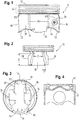
- a one-piece piston 10 has a piston head 12, an annular zone 14, a skirt wall 16 on the pressure side (DS), a skirt wall 18 on the counterpressure side and connecting walls 20 in between.
- A1, A2 and A3 indicate positions at which there can be a lifting groove for a locking ring that is formed during casting and is therefore particularly easy to manufacture, namely in the area of the top (A1), in the area of the bottom (A2) and / or one or both side areas (A3).
- FIG. 1 also to recognize their special shape. This is because they each have a shoulder 22 and a concave curvature 24.
- the concave curved recess at the lower end of the connecting wall extends higher on the counterpressure side, thus further in the direction of the piston head 12 than on the pressure side.
- at least one connecting wall on the counterpressure side can have at least one recess, in other words an opening, which in Fig. 1 is indicated with 26.
- the recess can be enlarged as indicated by dashed lines, preferably only on the counterpressure side. In other words, the recess can extend obliquely upwards approximately in the direction of the piston pin axis.
- the piston 10 according to the invention is shown in a side view or in a direction perpendicular to the piston pin axis, and it can be seen that the skirt wall 18 on the (to the viewer of the Fig. 2 directed) counter-pressure side is narrower than the distance between the respective outer edges 28 of the piston pin bosses.
- the narrowest width of the skirt wall 18 on the counterpressure side can be, for example, in a range from 0.22 to 0.28 of the piston diameter, while the corresponding width on the pressure side can be 0.27 to 0.33.
- the angle D at which the skirt wall widens in the direction of the lower end of the piston can be 0.08 to 0.12 times the piston diameter (specified in degrees) on the pressure side, while the angle on the counter pressure side is, for example 0.03 to 0.07 times the piston diameter (given in degrees).
- the dimension E according to Fig. 2 ie the distance between the lower end of the skirt wall and its narrowest point is, for example, about 5% of the product of the piston pin diameter and piston diameter (specified in millimeters), and 18 to 22% of this at the lower end of the skirt wall can be designed as in Fig. 2 shown, namely that the width is reduced here.
- the thickness of the shaft wall 18 can be in the region of (in Fig. 3 vertically running) center axis 2.0 to 2.4 mm plus 1% of the piston diameter, while 2.0 to 2.4 mm plus 2% of the piston diameter have proven to be advantageous for the pressure side.
- the connecting walls 20 on the pressure side are about 0.5 to 1 mm thicker than the above-described dimension of the skirt wall 18 on the pressure side on the piston center axis, and a value of about 0.15 to 0.35 mm thicker than that applies to the counter pressure side Thickness of the skirt wall on the counter-pressure side in the area of the piston axis.
- the connecting walls extend diverging from one another on both sides in the direction of the piston center axis, and on the pressure side they are connected from the outside at approximately a third of the axial extent (based on the piston pin) of the pin hub, while this connection is connected on the counter-pressure side is provided from the inside for a third of the reference value mentioned.
- the distance between the piston pin bosses in the lower area should be less than in the upper area.
- a curved, oval or “bean-shaped” coolant outlet 30 can also be seen, wherein a coolant inlet 32 can be located opposite, in other words, within the respective shaft wall 16 or 18. Additional coolant outlets 34 may be present in areas "next to" the piston pin bosses.
- the shaft and / or connecting wall can be made thickened, and a harmonious transition can advantageously be provided in order to reduce any notch effect. This applies in the same way to the area of the transition 38 to the piston pin bosses.
- a recess 42 is provided in order to save weight here.
- this recess can also be provided outside the connecting walls 20, for example in those areas in which the coolant outlets 34 are indicated and in the circumferential direction along the annular zone 14 on the inside of the piston. If such a recess is particularly important within the connecting (and the shaft) walls, as in FIG Fig. 4 to be recognized, is dispensed with, the cooling channel can advantageously be directed in the direction of the piston axis (in Fig. 4 vertically).
Landscapes
- Engineering & Computer Science (AREA)
- Mechanical Engineering (AREA)
- Chemical & Material Sciences (AREA)
- Combustion & Propulsion (AREA)
- General Engineering & Computer Science (AREA)
- Physics & Mathematics (AREA)
- Fluid Mechanics (AREA)
- Pistons, Piston Rings, And Cylinders (AREA)
Description
- Die Erfindung betrifft einen Kolben aus Stahl- oder Grauguss für einen Verbrennungsmotor mit einem Kühlkanal, Schaftwänden und Verbindungswänden zwischen den Schaftwänden, sowie ein Verfahren zur Herstellung eines Kolbens durch Stahl- oder Grauguss.
- Als Kolben für Verbrennungsmotoren sind zahlreiche gegossene Leichtmetallkolben bekannt, die einen oder mehrere Kühlkanäle aufweisen können. Zur Abstützung an den Zylinderwänden oder einer Zylinderlaufbuchse sind gegenüberliegende Schaftwände vorgesehen, die im Wesentlichen Abschnitte einer Zylindermantelfläche sind. Die Schaftwände sind durch sogenannte Verbindungswände verbunden, in denen Kolbenbolzennaben für die Aufnahme eines Kolbenbolzens vorgesehen sind, der sich durch das Auge eines zwischen den Verbindungswänden aufgenommenen Pleuels erstreckt.
- Ein gegossener Stahlkolben mit den oben genannten Merkmalen ist aus der
CN 102979641 A bekannt. DieDE 10 2013 099 155 A1 betrifft den Oberbegriff der Ansprüche 1 und 9. -
DE19908670 A1 undDE102007020447 A1 offenbaren weitere Kolben für einen Verbrennungsmotor. - Vor diesem Hintergrund liegt der Erfindung die Aufgabe zugrunde, einen verbesserten Kolben zu schaffen.
- Die Lösung dieser Aufgabe erfolgt durch den Gegenstand des Anspruchs 1.
- Demzufolge ist der erfindungsgemäße, einstückige Kolben aus Stahl- oder Grauguss zwischen Druck- und Gegendruckseite asymmetrisch. Mit anderen Worten sind die Schaft- und/oder Verbindungswände auf Druck- und Gegendruckseite unterschiedlich ausgebildet. Dies betrifft insbesondere die Breite der Schaftwände und/oder die Dicke und/oder die Erstreckung der Verbindungswände in Kolbenachsrichtung. Um den Anforderungen mit besonders einfachen Mitteln gerecht zu werden, kann beispielsweise die Breite der Schaftwand auf der Druckseite, also die Erstreckung der Schaftwand in Umfangsrichtung, größer sein, als auf der Gegendruckseite. In vorteilhafter Weise kann diese Gestaltung bereits beim Gießen des Rohlings für den erfindungsgemäßen Kolben vorgesehen werden, so dass die beschriebene Struktur mit geringem Aufwand herstellbar ist. Durch das Gießen kann insgesamt Gewicht eingespart werden. Ferner wird die Herstellung beispielsweise gegenüber herkömmlichen, zweiteiligen Stahlkolben, deren beide Teile beispielsweise durch Reibschweißen verbunden werden, wobei in diesem Zusammenhang auch ein Kühlkanal ausgebildet werden kann, vereinfacht und kann kostengünstiger gestaltet werden. Darüber hinaus sind die Gestaltungsmöglichkeiten durch den verwendeten Gießprozess äußerst vielfältig.
- Dies betrifft insbesondere auch die Dicke der Verbindungswände, die auf der Druckseite deutlich größer, insbesondere bis zu dem dreifachen Wert der Dicke auf der Gegendruckseite sein kann. Schließlich kann die Erstreckung der Verbindungswände in Kolbenachsrichtung an die Druck- und Gegendruckseite angepasst vorgenommen werden. Insbesondere können an dem unteren Ende der Verbindungswände Ausnehmungen vorgesehen werden, um Gewicht einzusparen. Diese Vorteile lassen sich mit einer Kostenreduzierung gegenüber herkömmlichen, zweiteiligen Kolben erreichen. Dies geht beispielsweise auch deshalb, weil bei zweiteiligen, geschmiedeten und reibgeschweißten Kolben umfangreiche Nachbearbeitungen erforderlich sind, um Spannungen infolge der genannten Bearbeitungsvorgänge zu reduzieren.
- Die Gestaltung der Verbindungswände sieht an ihrem vom Kolbenboden entfernt liegenden Ende, in Richtung der Kolbenbolzenachse betrachtet, einen Absatz und zumindest eine konkave Krümmung vor. Durch die Aussparung infolge der konkaven Krümmung kann Gewicht eingespart werden, und der Absatz kann in vorteilhafter Weise eine definierte Anordnung des Kolbens an einer Aufnahme zur Bearbeitung, beispielsweise durch Drehen, gewährleisten.
- Für die auftretenden Belastungen hat es sich darüber hinaus als vorteilhaft erwiesen, dass sich zumindest eine Schaftwand in einer sich von dem Kolbenboden entfernenden Richtung verbreitert.
- Vorteilhafte Weiterbildungen des erfindungsgemäßen Kolbens sind in den weiteren Ansprüchen beschrieben.
- Ferner können die Belastungen besonders gut aufgenommen werden, wenn sich zumindest eine Schaftwand in Richtung zumindest einer Verbindungswand verdickt.
- Gewicht kann in besonderem Maße dadurch eingespart werden, dass an der Unterseite des Kolbens gewissermaßen unterhalb des Kühlkanals, das heißt in Richtung der Kolbenachse weiter vom Kolbenboden entfernt als der Kühlkanal zumindest eine Ausnehmung ausgebildet ist. Mit anderen Worten kann sich die Ausnehmung innerhalb und/oder außerhalb der Verbindungswände an der genannten Stelle befinden.
- Für die Aus- und Einlässe des Kühlkanals wird derzeit bevorzugt, dass zumindest ein Kühlkanaleinlass zumindest gleich groß oder größer ist als zumindest ein Kühlkanalauslass. Dies bietet Vorteile, beispielsweise, wenn in dem zugehörigen Motor schräge Öldüsen verbaut sind. Es kann jedoch Anwendungsfälle geben, bei denen zumindest ein Auslass größer ist als zumindest ein Einlass.
- Für zumindest einen Kühlkanalauslass wird ferner bevorzugt, dass er einen Strömungsdiffusor aufweist. Hierbei handelt es sich im Wesentlichen um eine gerundete Rippe an der oberen Begrenzung des Kühlkanals, in etwa mittig über dem Kühlkanalauslass, so dass das heranströmende Kühlmittel in günstiger Weise in Richtung des Auslasses abgelenkt wird.
- Für zumindest einen Kühlkanalein- und/oder -auslass wird ferner derzeit bevorzugt, dass er oval oder elliptisch geformt ist. Im Hinblick auf den Einlass kann hierdurch auch bei schrägstehenden Öldüsen sichergestellt werden, dass genügend Kühlmittel in den Kühlkanal eintritt. Im Hinblick auf den Auslass bietet ein vergleichsweise großer, oval oder elliptisch geformter Auslass den Vorteil, dass das erwärmte Kühlmittel den Kühlkanal sicher verlässt und das Nachströmen von kühlem, und somit zur Aufnahme von Wärme geeignetem Kühlmittel nicht behindert.
- Es wird ferner bevorzugt, dass der erfindungsgemäße, Kolben zumindest eine Kolbenbolzennabe aufweist, die in einem oberen und/oder unteren und/oder in zumindest einem seitlichen Bereich eine Aushebenut für einen Sicherungsring aufweist. Diesbezüglich besteht ein besonderer Vorteil in der Herstellung durch Gießen darin, dass eine derartige Aushebenut bereits beim Gießen ausgebildet werden kann, und somit eine gesonderte Bearbeitung entfallen kann.
- Für die weitere Gewichtseinsparung ist es darüber hinaus vorteilhaft, wenn zumindest eine Verbindungswand, bevorzugt auf der Gegendruckseite, zumindest eine Aussparung, mit anderen Worten eine Öffnung aufweist.
- Die Erfindung betrifft ferner ein Verfahren zur Herstellung eines Kolbens, bei dem der vorangehend beschriebene Kolben durch Stahl- oder Grauguss ausgebildet wird. Hierdurch können die entsprechenden Vorteile erreicht werden, und es sei an dieser Stelle erwähnt, dass sämtliche vorangehend und nachfolgend lediglich im Zusammenhang mit dem Kolben genannten Merkmale bei dem erfindungsgemäß Verfahren angewendet werden können, und umgekehrt.
- Die Eigenschaften des Kolbens im Hinblick auf die weitere Bearbeitung, die Ermüdungsfestigkeit und den Widerstand gegen thermomechanische Belastungen können in vorteilhafter Weise dadurch verbessert werden, dass der Kolben wärmebehandelt wird.
- Für den bei der Herstellung zur Ausbildung des Kühlkanals verwendeten Kern hat es sich darüber hinaus als vorteilhaft erwiesen, wenn dieser Sand und/oder Wachs aufweist.
- Ferner können die Eigenschaften des Kerns verbessert werden, wenn dieser beschichtet ist.
- Für die Herstellung des Kerns wird ferner ein Press- oder ein additives oder generatives Herstellungsverfahren bevorzugt.
- Nachfolgend werden bevorzugte Ausführungsbeispiele der Erfindung unter Bezugnahme auf die Zeichnungen näher erläutert. Es zeigen:
- Fig. 1
- einen erfindungsgemäßen Kolben in einer Seitenansicht in Richtung der Kolbenbolzenachse;
- Fig. 2
- den erfindungsgemäßen Kolben in einer Seitenansicht in einer Richtung senkrecht zur Kolbenbolzenachse;
- Fig. 3
- eine Unteransicht eines erfindungsgemäßen Kolbens; und
- Fig. 4
- eine Schnittansicht eines erfindungsgemäßen Kolbens.
- Wie in
Fig. 1 zu erkennen ist, weist ein erfindungsgemäßer, einstückiger Kolben 10 einen Kolbenboden 12, ein Ringfeld 14, eine Schaftwand 16 auf der Druckseite (DS), eine Schaftwand 18 auf der Gegendruckseite und dazwischenliegende Verbindungswände 20 auf. InFig. 1 sind mit A1, A2 und A3 Positionen angedeutet, an denen sich eine beim Gießen ausgebildete und deshalb besonders einfach herzustellende Aushebenut für einen Sicherungsring befinden kann, nämlich im Bereich der Oberseite (A1), im Bereich der Unterseite (A2) und/oder einem oder beiden seitlichen Bereichen (A3). - An den jeweiligen unteren Enden der Verbindungswände 20 ist in
Fig. 1 ferner deren besondere Form zu erkennen. Sie weisen nämlich jeweils einen Absatz 22 und eine konkave Krümmung 24 auf. Die konkav gekrümmte Aussparung am unteren Ende der Verbindungswand erstreckt sich auf der Gegendruckseite höher, also weiter in Richtung des Kolbenbodens 12, als auf der Druckseite. ZurFig. 1 sei ergänzend erwähnt, dass insbesondere zumindest eine Verbindungswand auf der Gegendruckseite zumindest eine Aussparung, mit anderen Worten eine Öffnung aufweisen kann, die inFig. 1 mit 26 angedeutet ist. Zu der Kontur auf der Gegendruckseite sei ergänzend erwähnt, dass hier ein zweiter Absatz 22 nahe der Kolbenbolzennabe vorhanden ist. Ferner kann die Aussparung wie mit gestrichelten Linien angezeigt, bevorzugt lediglich auf der Gegendruckseite, vergrößert werden. Mit anderen Worten kann sich die Aussparung schräg nach oben in etwa in Richtung der Kolbenbolzenachse erstrecken. - Aus der
Fig. 2 ist der erfindungsgemäße Kolben 10 in einer Seitenansicht oder in einer Richtung senkrecht zur Kolbenbolzenachse gezeigt, und es ist zu erkennen, dass die Schaftwand 18 auf der (zum Betrachter derFig. 2 gerichteten) Gegendruckseite schmaler ist, als der Abstand zwischen den jeweils äußeren Rändern 28 der Kolbenbolzennaben. Es sei erwähnt, dass die schmalste Breite der Schaftwand 18 auf der Gegendruckseite beispielsweise bei einem Bereich von 0,22 bis 0,28 des Kolbendurchmessers liegen kann, während die entsprechende Breite auf der Druckseite bei 0,27 bis 0,33 liegen kann. Der Winkel D, mit dem sich die Schaftwand jeweils in Richtung des unteren Endes des Kolbens verbreitert, kann bei 0,08 bis 0,12 mal dem Kolbendurchmesser (angegeben in Grad) liegen, auf der Druckseite, während der Winkel auf der Gegendruckseite beispielsweise bei 0,03 bis 0,07 mal dem Kolbendurchmesser (angegeben in Grad) liegen kann. Die Abmessung E gemäßFig. 2 , d. h. die Entfernung zwischen dem unteren Ende der Schaftwand und dessen schmalster Stelle beträgt beispielsweise etwa 5 % des Produkts von Kolbenbolzendurchmesser und Kolbendurchmesser (in Millimeter angegeben), und 18 bis 22 % davon können am unteren Ende der Schaftwand so gestaltet sein wie inFig. 2 gezeigt, nämlich dass sich die Breite hier verringert. - In
Fig. 3 sind weitere Abmessungen zu erkennen. Beispielsweise kann die Dicke der Schaftwand 18 im Bereich der (inFig. 3 vertikal verlaufenden) Mittelachse 2,0 bis 2,4 mm zuzüglich 1 % des Kolbendurchmessers betragen, während sich für die Druckseite 2,0 bis 2,4 mm zuzüglich 2 % des Kolbendurchmessers als vorteilhaft erwiesen haben. Die Verbindungswände 20 auf der Druckseite sind etwa 0,5 bis 1 mm dicker als die oben beschriebene Abmessung der Schaftwand 18 auf der Druckseite an der Kolbenmittelachse, und für die Gegendruckseite gilt ein Wert von etwa 0,15 bis 0,35 mm dicker als die Dicke der Schaftwand auf der Gegendruckseite im Bereich der Kolbenachse. Ferner erstrecken sich die Verbindungswände auf beiden Seiten in Richtung der Kolbenmittelachse voneinander divergierend, und auf der Druckseite sind sie in etwa bei einem Drittel der axialen Erstreckung (bezogen auf den Kolbenbolzen) der Bolzennabe von der Außenseite her angebunden, während diese Anbindung auf der Gegendruckseite etwa bei einem Drittel der genannten Bezugsgröße von der Innenseite her vorgesehen ist. An dieser Innenseite kann der Abstand zwischen den Kolbenbolzennaben im unteren Bereich (inFig. 3 zu dem Betrachter gerichtet) geringer sein als im oberen Bereich. - In der Unteransicht von
Fig. 3 ist ferner ein gekrümmt ovaler oder in gewisser Weise "bohnenförmiger" Kühlmittelauslass 30 zu erkennen, wobei sich ein Kühlmitteleinlass 32 gegenüber, mit anderen Worten innerhalb der jeweiligen Schaftwand 16 bzw. 18 befinden kann. In Bereichen "neben" den Kolbenbolzennaben können zusätzliche Kühlmittelauslässe 34 vorhanden sein. An dem jeweiligen Übergang 36 von der Schaftwand zu der Verbindungswand können die Schaft- und/oder Verbindungswand verdickt ausgeführt sein, und es kann in vorteilhafter Weise ein harmonischer Übergang vorgesehen sein, um jegliche Kerbwirkung zu vermindern. Dies gilt in gleicher Weise für den Bereich des Übergangs 38 zu den Kolbenbolzennaben. - In
Fig. 4 ist in der Schnittdarstellung erstmalig der Kühlkanal 40 zu erkennen, unterhalb dessen eine Ausnehmung 42 vorgesehen ist, um hier Gewicht einzusparen. Wie ergänzend in der Unteransicht vonFig. 3 erkennbar ist, kann diese Ausnehmung auch außerhalb der Verbindungswände 20 vorgesehen sein, beispielsweise in denjenigen Bereichen, in denen die Kühlmittelauslässe 34 angedeutet sind sowie in Umfangsrichtung entlang des Ringfeldes 14 an der Innenseite des Kolbens. Wenn auf eine derartige Ausnehmung insbesondere innerhalb der Verbindungs- (und der Schaft-)Wände, wie inFig. 4 zu erkennen, verzichtet wird, kann der Kühlkanal in vorteilhafter Weise in Richtung der Kolbenachse (inFig. 4 vertikal) vergrößert werden.
Claims (13)
- Kolben (10) aus Stahl- oder Grauguss für einen Verbrennungsmotor, mit einem Kühlkanal (40), Schaftwänden (16, 18) und Verbindungswänden (20) zwischen den Schaftwänden (16, 18),
wobei dieser im Hinblick auf die Breite (C) der Schaftwände (16, 18) und Dicke und Erstreckung der Verbindungswände (20) in Kolbenachsrichtung zwischen Druck- (DS) und Gegendruckseite asymmetrisch ist,
wobei zumindest eine Verbindungswand (20) an ihrem vom Kolbenboden (12) entfernt liegenden Ende in Richtung der Kolbenbolzenachse betrachtet zumindest einen Absatz (22) und zumindest eine konkave Krümmung (24) aufweist, und
wobei sich die konkav gekrümmte Aussparung am unteren Ende der Verbindungswand auf der Gegendruckseite weiter in Richtung des Kolbenbodens (12) erstreckt als auf der Druckseite,
wobei zumindest eine Schaftwand (16, 18) in einer sich von dem Kolbenboden (12) entfernenden Richtung verbreitert ist. - Kolben (10) für einen Verbrennungsmotor nach einem der vorangehenden Ansprüche,
dadurch gekennzeichnet, dass
zumindest eine Schaftwand (16, 18) in Richtung zumindest einer Verbindungswand (20) verdickt (36) ist. - Kolben (10) für einen Verbrennungsmotor nach einem der vorangehenden Ansprüche,
dadurch gekennzeichnet, dass
unterhalb des Kühlkanals (40), das heißt in Kolbenachsrichtung weiter von dem Kolbenboden (12) entfernt als der Kühlkanal (40) zumindest eine Ausnehmung (42) ausgebildet ist. - Kolben (10) für einen Verbrennungsmotor nach einem der vorangehenden Ansprüche,
dadurch gekennzeichnet, dass
zumindest ein Kühlkanaleinlass (32) gleich groß oder größer ist als zumindest ein Kühlkanalauslass (30). - Kolben (10) für einen Verbrennungsmotor nach einem der vorangehenden Ansprüche,
dadurch gekennzeichnet, dass
zumindest ein Kühlkanalauslass (30) einen Strömungsdiffusor aufweist. - Kolben (10) für einen Verbrennungsmotor nach einem der vorangehenden Ansprüche,
dadurch gekennzeichnet, dass
zumindest ein Kühlkanalauslass (30) oval oder elliptisch geformt ist. - Kolben (10) für einen Verbrennungsmotor nach einem der vorangehenden Ansprüche, ferner mit zumindest einer Kolbenbolzennabe, die in einem oberen Bereich (A1) und/oder einem unteren Bereich (A2) und/oder in zumindest einem seitlichen Bereich (A3) eine Aushebenut für einen Sicherungsring aufweist.
- Kolben (10) für einen Verbrennungsmotor nach einem der vorangehenden Ansprüche,
dadurch gekennzeichnet, dass
zumindest eine Verbindungswand (20) zumindest eine Öffnung (26) aufweist. - Verfahren zur Herstellung eines Kolbens (10) für einen Verbrennungsmotor mittels Stahl- oder Grauguss mit einem Kühlkanal (40), Schaftwänden (16, 18) und Verbindungswänden (20) zwischen den Schaftwänden (16, 18),
wobei der Kolben derart gegossen wird, dass er im Hinblick auf die Breite der Schaftwände (16, 18) und Dicke und Erstreckung der Verbindungswände (20) in Kolbenachsrichtung zwischen Druck- und Gegendruckseite asymmetrisch ausgebildet wird, und
wobei an zumindest einer Verbindungswand (20) an ihrem vom Kolbenboden (12) entfernt liegenden Ende in Richtung der Bolzenachse betrachtet zumindest ein Absatz (22) und zumindest eine konkave Krümmung (24) ausgebildet wird, und
wobei sich die konkav gekrümmte Aussparung am unteren Ende der Verbindungswand auf der Gegendruckseite weiter in Richtung des Kolbenbodens (12) erstreckt als auf der Druckseite, und
wobei zumindest eine Schaftwand (16, 18) in einer sich von dem Kolbenboden (12) entfernenden Richtung verbreitert ist. - Verfahren nach Anspruch 9,
dadurch gekennzeichnet, dass
der Kolben wärmebehandelt wird. - Verfahren nach einem der Ansprüche 9 oder 10,
dadurch gekennzeichnet, dass
ein zur Herstellung des Kühlkanals (40) verwendeter Kern Sand und/oder Wachs aufweist. - Verfahren nach einem der Ansprüche 9 bis 10,
dadurch gekennzeichnet, dass
ein zur Herstellung des Kühlkanals (40) verwendeter Kern beschichtet ist. - Verfahren nach einem der Ansprüche 9 bis 12,
dadurch gekennzeichnet, dass
ein zur Herstellung des Kühlkanals (40) verwendeter Kern durch ein Press- oder ein additives oder generatives Herstellungsverfahren hergestellt wird.
Applications Claiming Priority (2)
| Application Number | Priority Date | Filing Date | Title |
|---|---|---|---|
| DE102016201628.8A DE102016201628A1 (de) | 2016-02-03 | 2016-02-03 | Kolben aus Stahl- oder Grauguss für einen Verbrennungsmotor und Verfahren zur Herstellung eines Kolbens durch Stahl- oder Grauguss |
| PCT/EP2017/052235 WO2017134155A1 (de) | 2016-02-03 | 2017-02-02 | Kolben aus stahl- oder grauguss für einen verbrennungsmotor und verfahren zur herstellung eines kolbens durch stahl- oder grauguss |
Publications (2)
| Publication Number | Publication Date |
|---|---|
| EP3411585A1 EP3411585A1 (de) | 2018-12-12 |
| EP3411585B1 true EP3411585B1 (de) | 2020-09-30 |
Family
ID=57965932
Family Applications (1)
| Application Number | Title | Priority Date | Filing Date |
|---|---|---|---|
| EP17703381.8A Not-in-force EP3411585B1 (de) | 2016-02-03 | 2017-02-02 | Kolben aus stahl- oder grauguss für einen verbrennungsmotor und verfahren zur herstellung eines kolbens durch stahl- oder grauguss |
Country Status (4)
| Country | Link |
|---|---|
| EP (1) | EP3411585B1 (de) |
| KR (1) | KR20180105714A (de) |
| DE (1) | DE102016201628A1 (de) |
| WO (1) | WO2017134155A1 (de) |
Families Citing this family (3)
| Publication number | Priority date | Publication date | Assignee | Title |
|---|---|---|---|---|
| EP3710686B1 (de) | 2017-11-14 | 2026-02-25 | KS Kolbenschmidt GmbH | Stahlkolben mit optimiertem design |
| DE102019216252A1 (de) | 2019-10-22 | 2021-04-22 | Mahle International Gmbh | Kolben für eine Brennkraftmaschine |
| CN116727606B (zh) * | 2023-06-15 | 2026-03-24 | 陕西柴油机重工有限公司 | 高强度灰铸铁柴油机机体无冒口铸造成型方法 |
Citations (2)
| Publication number | Priority date | Publication date | Assignee | Title |
|---|---|---|---|---|
| DE19908670A1 (de) * | 1999-02-27 | 2000-11-02 | Federal Mogul Burscheid Gmbh | Kolben für Brennkraftmaschinen |
| DE102007020447A1 (de) * | 2007-04-27 | 2008-10-30 | Mahle International Gmbh | Kolben für einen Verbrennungsmotor |
Family Cites Families (17)
| Publication number | Priority date | Publication date | Assignee | Title |
|---|---|---|---|---|
| DE4109160C3 (de) * | 1991-03-20 | 2000-11-30 | Federal Mogul Nuernberg Gmbh | Kolben für Brennkraftmaschinen |
| JPH0667838U (ja) * | 1993-02-23 | 1994-09-22 | 株式会社ユニシアジェックス | 内燃機関のピストン構造 |
| DE4340891A1 (de) * | 1993-12-01 | 1995-06-08 | Mahle Gmbh | Hubkolben für Verbrennungsmotoren aus insbesondere Leichtmetall |
| JP3091141B2 (ja) * | 1996-09-27 | 2000-09-25 | 川崎重工業株式会社 | 内燃機関用ピストン |
| JPH11303674A (ja) * | 1998-04-24 | 1999-11-02 | Unisia Jecs Corp | 内燃機関のピストン |
| JP2000039066A (ja) * | 1998-07-23 | 2000-02-08 | Toyota Motor Corp | ピストン |
| WO2007025686A1 (de) * | 2005-08-29 | 2007-03-08 | Ks Kolbenschmidt Gmbh | Leichtbaukolben |
| DE102007018932A1 (de) * | 2007-04-21 | 2008-10-23 | Ks Kolbenschmidt Gmbh | Belastungsoptimierter Innenraum eines Kolbens |
| DE102009032379A1 (de) * | 2008-08-13 | 2010-02-18 | Mahle International Gmbh | Kolben für einen Verbrennungsmotor |
| US9970384B2 (en) * | 2009-11-06 | 2018-05-15 | Federal-Mogul Llc | Steel piston with cooling gallery and method of construction thereof |
| DE102009059056A1 (de) * | 2009-12-18 | 2011-06-22 | MAHLE International GmbH, 70376 | Kolben für einen Verbrennungsmotor |
| EP2541004B1 (de) * | 2010-02-23 | 2014-05-14 | Honda Motor Co., Ltd. | Kolbenkühlvorrichtung |
| DE102010053925A1 (de) * | 2010-12-09 | 2012-06-14 | Mahle International Gmbh | Kolben für einen Verbrennungsmotor und Verfahren zu seiner Herstellung |
| DE102012203570A1 (de) * | 2012-03-07 | 2013-09-12 | Mahle International Gmbh | Gegossener Leichtmetallkolben, insbesondere ein Aluminiumkolben |
| CN102979641B (zh) | 2012-12-06 | 2015-06-17 | 湖南江滨机器(集团)有限责任公司 | 整体式铸钢活塞及其制造方法 |
| DE102013009155A1 (de) * | 2013-05-31 | 2014-12-04 | Mahle International Gmbh | Kolben für einen Verbrennungsmotor |
| DE102014211350A1 (de) * | 2013-06-14 | 2014-12-18 | Ks Kolbenschmidt Gmbh | Gussverfahren zur Herstellung eines Kolbens und Kolben für Brennkraftmaschinen |
-
2016
- 2016-02-03 DE DE102016201628.8A patent/DE102016201628A1/de not_active Ceased
-
2017
- 2017-02-02 KR KR1020187025507A patent/KR20180105714A/ko not_active Ceased
- 2017-02-02 EP EP17703381.8A patent/EP3411585B1/de not_active Not-in-force
- 2017-02-02 WO PCT/EP2017/052235 patent/WO2017134155A1/de not_active Ceased
Patent Citations (2)
| Publication number | Priority date | Publication date | Assignee | Title |
|---|---|---|---|---|
| DE19908670A1 (de) * | 1999-02-27 | 2000-11-02 | Federal Mogul Burscheid Gmbh | Kolben für Brennkraftmaschinen |
| DE102007020447A1 (de) * | 2007-04-27 | 2008-10-30 | Mahle International Gmbh | Kolben für einen Verbrennungsmotor |
Also Published As
| Publication number | Publication date |
|---|---|
| EP3411585A1 (de) | 2018-12-12 |
| KR20180105714A (ko) | 2018-09-28 |
| DE102016201628A1 (de) | 2017-08-03 |
| WO2017134155A1 (de) | 2017-08-10 |
Similar Documents
| Publication | Publication Date | Title |
|---|---|---|
| DE68914179T2 (de) | Kolben. | |
| EP3027874B1 (de) | Leichtbau eines dieselkolbens | |
| DE60220925T2 (de) | Einstückiger kolben für dieselmotoren | |
| EP2222947B1 (de) | Gusskolben mit stützrippen und verfahren zur herstellung eines solchen kolbens | |
| DE102012014193A1 (de) | Kolben für einen Verbrennungsmotor | |
| EP3334918B1 (de) | Kolben für eine brennkraftmaschine | |
| DE102013215538B4 (de) | Kolben für einen Verbrennungsmotor | |
| EP2823166A1 (de) | Gegossener leichtmetallkolben, insbesondere ein aluminiumkolben | |
| WO2007028466A1 (de) | Kolben für eine brennkraftmaschine | |
| EP3746651B1 (de) | Hubkolben für eine hubkolbenbrennkraftmaschine sowie verwendung eines hubkolbens in einer hubkolbenbrennkraftmaschine | |
| EP2771558B1 (de) | Kolben und pleuel für eine brennkraftmaschine | |
| WO2017134155A1 (de) | Kolben aus stahl- oder grauguss für einen verbrennungsmotor und verfahren zur herstellung eines kolbens durch stahl- oder grauguss | |
| DE3609019C1 (en) | Method for the production of the hub hole of a trunk piston, particularly for internal combustion engines | |
| EP3004611A1 (de) | Kolben für einen verbrennungsmotor | |
| WO2016120246A1 (de) | Kolben für einen verbrennungsmotor sowie verfahren zur herstellung des kolbens für einen verbrennungsmotor | |
| WO2019238528A1 (de) | Gegossener kolben für einen verbrennungsmotor, aus einem material auf eisenbasis | |
| DE102017215834A1 (de) | Kolben | |
| EP3615784B1 (de) | Einteiliger, gegossener kolben für einen verbrennungsmotor | |
| DE10126493B4 (de) | Kolben mit zu den Hauptachsen geneigtem Kühlkanal | |
| DE10113639A1 (de) | Kühlkanal für einen flüssigkeitsgekühlten Kolben | |
| DE19953384C1 (de) | Kolben | |
| EP1704319B1 (de) | Zylinderkurbelgehäuse mit zylinderlaufbuchse | |
| EP3545182B1 (de) | Stahlkolben für einen verbrennungsmotor | |
| DE3714400A1 (de) | Kolben fuer brennkraftmaschinen | |
| DE102009001888B4 (de) | Kolben für einen Verbrennungsmotor |
Legal Events
| Date | Code | Title | Description |
|---|---|---|---|
| STAA | Information on the status of an ep patent application or granted ep patent |
Free format text: STATUS: UNKNOWN |
|
| STAA | Information on the status of an ep patent application or granted ep patent |
Free format text: STATUS: THE INTERNATIONAL PUBLICATION HAS BEEN MADE |
|
| PUAI | Public reference made under article 153(3) epc to a published international application that has entered the european phase |
Free format text: ORIGINAL CODE: 0009012 |
|
| STAA | Information on the status of an ep patent application or granted ep patent |
Free format text: STATUS: REQUEST FOR EXAMINATION WAS MADE |
|
| 17P | Request for examination filed |
Effective date: 20180727 |
|
| AK | Designated contracting states |
Kind code of ref document: A1 Designated state(s): AL AT BE BG CH CY CZ DE DK EE ES FI FR GB GR HR HU IE IS IT LI LT LU LV MC MK MT NL NO PL PT RO RS SE SI SK SM TR |
|
| AX | Request for extension of the european patent |
Extension state: BA ME |
|
| DAV | Request for validation of the european patent (deleted) | ||
| DAX | Request for extension of the european patent (deleted) | ||
| GRAP | Despatch of communication of intention to grant a patent |
Free format text: ORIGINAL CODE: EPIDOSNIGR1 |
|
| STAA | Information on the status of an ep patent application or granted ep patent |
Free format text: STATUS: GRANT OF PATENT IS INTENDED |
|
| INTG | Intention to grant announced |
Effective date: 20200430 |
|
| GRAS | Grant fee paid |
Free format text: ORIGINAL CODE: EPIDOSNIGR3 |
|
| GRAA | (expected) grant |
Free format text: ORIGINAL CODE: 0009210 |
|
| STAA | Information on the status of an ep patent application or granted ep patent |
Free format text: STATUS: THE PATENT HAS BEEN GRANTED |
|
| AK | Designated contracting states |
Kind code of ref document: B1 Designated state(s): AL AT BE BG CH CY CZ DE DK EE ES FI FR GB GR HR HU IE IS IT LI LT LU LV MC MK MT NL NO PL PT RO RS SE SI SK SM TR |
|
| REG | Reference to a national code |
Ref country code: GB Ref legal event code: FG4D Free format text: NOT ENGLISH Ref country code: CH Ref legal event code: EP |
|
| REG | Reference to a national code |
Ref country code: AT Ref legal event code: REF Ref document number: 1319028 Country of ref document: AT Kind code of ref document: T Effective date: 20201015 Ref country code: DE Ref legal event code: R096 Ref document number: 502017007506 Country of ref document: DE |
|
| REG | Reference to a national code |
Ref country code: IE Ref legal event code: FG4D Free format text: LANGUAGE OF EP DOCUMENT: GERMAN |
|
| PG25 | Lapsed in a contracting state [announced via postgrant information from national office to epo] |
Ref country code: SE Free format text: LAPSE BECAUSE OF FAILURE TO SUBMIT A TRANSLATION OF THE DESCRIPTION OR TO PAY THE FEE WITHIN THE PRESCRIBED TIME-LIMIT Effective date: 20200930 Ref country code: FI Free format text: LAPSE BECAUSE OF FAILURE TO SUBMIT A TRANSLATION OF THE DESCRIPTION OR TO PAY THE FEE WITHIN THE PRESCRIBED TIME-LIMIT Effective date: 20200930 Ref country code: BG Free format text: LAPSE BECAUSE OF FAILURE TO SUBMIT A TRANSLATION OF THE DESCRIPTION OR TO PAY THE FEE WITHIN THE PRESCRIBED TIME-LIMIT Effective date: 20201230 Ref country code: NO Free format text: LAPSE BECAUSE OF FAILURE TO SUBMIT A TRANSLATION OF THE DESCRIPTION OR TO PAY THE FEE WITHIN THE PRESCRIBED TIME-LIMIT Effective date: 20201230 Ref country code: GR Free format text: LAPSE BECAUSE OF FAILURE TO SUBMIT A TRANSLATION OF THE DESCRIPTION OR TO PAY THE FEE WITHIN THE PRESCRIBED TIME-LIMIT Effective date: 20201231 Ref country code: HR Free format text: LAPSE BECAUSE OF FAILURE TO SUBMIT A TRANSLATION OF THE DESCRIPTION OR TO PAY THE FEE WITHIN THE PRESCRIBED TIME-LIMIT Effective date: 20200930 |
|
| PG25 | Lapsed in a contracting state [announced via postgrant information from national office to epo] |
Ref country code: LV Free format text: LAPSE BECAUSE OF FAILURE TO SUBMIT A TRANSLATION OF THE DESCRIPTION OR TO PAY THE FEE WITHIN THE PRESCRIBED TIME-LIMIT Effective date: 20200930 Ref country code: RS Free format text: LAPSE BECAUSE OF FAILURE TO SUBMIT A TRANSLATION OF THE DESCRIPTION OR TO PAY THE FEE WITHIN THE PRESCRIBED TIME-LIMIT Effective date: 20200930 |
|
| REG | Reference to a national code |
Ref country code: NL Ref legal event code: MP Effective date: 20200930 |
|
| REG | Reference to a national code |
Ref country code: LT Ref legal event code: MG4D |
|
| PG25 | Lapsed in a contracting state [announced via postgrant information from national office to epo] |
Ref country code: PT Free format text: LAPSE BECAUSE OF FAILURE TO SUBMIT A TRANSLATION OF THE DESCRIPTION OR TO PAY THE FEE WITHIN THE PRESCRIBED TIME-LIMIT Effective date: 20210201 Ref country code: RO Free format text: LAPSE BECAUSE OF FAILURE TO SUBMIT A TRANSLATION OF THE DESCRIPTION OR TO PAY THE FEE WITHIN THE PRESCRIBED TIME-LIMIT Effective date: 20200930 Ref country code: CZ Free format text: LAPSE BECAUSE OF FAILURE TO SUBMIT A TRANSLATION OF THE DESCRIPTION OR TO PAY THE FEE WITHIN THE PRESCRIBED TIME-LIMIT Effective date: 20200930 Ref country code: LT Free format text: LAPSE BECAUSE OF FAILURE TO SUBMIT A TRANSLATION OF THE DESCRIPTION OR TO PAY THE FEE WITHIN THE PRESCRIBED TIME-LIMIT Effective date: 20200930 Ref country code: EE Free format text: LAPSE BECAUSE OF FAILURE TO SUBMIT A TRANSLATION OF THE DESCRIPTION OR TO PAY THE FEE WITHIN THE PRESCRIBED TIME-LIMIT Effective date: 20200930 Ref country code: SM Free format text: LAPSE BECAUSE OF FAILURE TO SUBMIT A TRANSLATION OF THE DESCRIPTION OR TO PAY THE FEE WITHIN THE PRESCRIBED TIME-LIMIT Effective date: 20200930 |
|
| PG25 | Lapsed in a contracting state [announced via postgrant information from national office to epo] |
Ref country code: AL Free format text: LAPSE BECAUSE OF FAILURE TO SUBMIT A TRANSLATION OF THE DESCRIPTION OR TO PAY THE FEE WITHIN THE PRESCRIBED TIME-LIMIT Effective date: 20200930 Ref country code: ES Free format text: LAPSE BECAUSE OF FAILURE TO SUBMIT A TRANSLATION OF THE DESCRIPTION OR TO PAY THE FEE WITHIN THE PRESCRIBED TIME-LIMIT Effective date: 20200930 Ref country code: PL Free format text: LAPSE BECAUSE OF FAILURE TO SUBMIT A TRANSLATION OF THE DESCRIPTION OR TO PAY THE FEE WITHIN THE PRESCRIBED TIME-LIMIT Effective date: 20200930 Ref country code: IS Free format text: LAPSE BECAUSE OF FAILURE TO SUBMIT A TRANSLATION OF THE DESCRIPTION OR TO PAY THE FEE WITHIN THE PRESCRIBED TIME-LIMIT Effective date: 20210130 |
|
| PG25 | Lapsed in a contracting state [announced via postgrant information from national office to epo] |
Ref country code: NL Free format text: LAPSE BECAUSE OF FAILURE TO SUBMIT A TRANSLATION OF THE DESCRIPTION OR TO PAY THE FEE WITHIN THE PRESCRIBED TIME-LIMIT Effective date: 20200930 Ref country code: SK Free format text: LAPSE BECAUSE OF FAILURE TO SUBMIT A TRANSLATION OF THE DESCRIPTION OR TO PAY THE FEE WITHIN THE PRESCRIBED TIME-LIMIT Effective date: 20200930 |
|
| REG | Reference to a national code |
Ref country code: DE Ref legal event code: R097 Ref document number: 502017007506 Country of ref document: DE |
|
| PLBE | No opposition filed within time limit |
Free format text: ORIGINAL CODE: 0009261 |
|
| STAA | Information on the status of an ep patent application or granted ep patent |
Free format text: STATUS: NO OPPOSITION FILED WITHIN TIME LIMIT |
|
| PG25 | Lapsed in a contracting state [announced via postgrant information from national office to epo] |
Ref country code: DK Free format text: LAPSE BECAUSE OF FAILURE TO SUBMIT A TRANSLATION OF THE DESCRIPTION OR TO PAY THE FEE WITHIN THE PRESCRIBED TIME-LIMIT Effective date: 20200930 |
|
| 26N | No opposition filed |
Effective date: 20210701 |
|
| PG25 | Lapsed in a contracting state [announced via postgrant information from national office to epo] |
Ref country code: MC Free format text: LAPSE BECAUSE OF FAILURE TO SUBMIT A TRANSLATION OF THE DESCRIPTION OR TO PAY THE FEE WITHIN THE PRESCRIBED TIME-LIMIT Effective date: 20200930 |
|
| GBPC | Gb: european patent ceased through non-payment of renewal fee |
Effective date: 20210202 |
|
| REG | Reference to a national code |
Ref country code: BE Ref legal event code: MM Effective date: 20210228 |
|
| PG25 | Lapsed in a contracting state [announced via postgrant information from national office to epo] |
Ref country code: LU Free format text: LAPSE BECAUSE OF NON-PAYMENT OF DUE FEES Effective date: 20210202 Ref country code: IT Free format text: LAPSE BECAUSE OF FAILURE TO SUBMIT A TRANSLATION OF THE DESCRIPTION OR TO PAY THE FEE WITHIN THE PRESCRIBED TIME-LIMIT Effective date: 20200930 Ref country code: LI Free format text: LAPSE BECAUSE OF NON-PAYMENT OF DUE FEES Effective date: 20210228 Ref country code: CH Free format text: LAPSE BECAUSE OF NON-PAYMENT OF DUE FEES Effective date: 20210228 |
|
| PG25 | Lapsed in a contracting state [announced via postgrant information from national office to epo] |
Ref country code: SI Free format text: LAPSE BECAUSE OF FAILURE TO SUBMIT A TRANSLATION OF THE DESCRIPTION OR TO PAY THE FEE WITHIN THE PRESCRIBED TIME-LIMIT Effective date: 20200930 |
|
| PG25 | Lapsed in a contracting state [announced via postgrant information from national office to epo] |
Ref country code: IE Free format text: LAPSE BECAUSE OF NON-PAYMENT OF DUE FEES Effective date: 20210202 Ref country code: GB Free format text: LAPSE BECAUSE OF NON-PAYMENT OF DUE FEES Effective date: 20210202 Ref country code: FR Free format text: LAPSE BECAUSE OF NON-PAYMENT OF DUE FEES Effective date: 20210228 |
|
| PG25 | Lapsed in a contracting state [announced via postgrant information from national office to epo] |
Ref country code: IS Free format text: LAPSE BECAUSE OF FAILURE TO SUBMIT A TRANSLATION OF THE DESCRIPTION OR TO PAY THE FEE WITHIN THE PRESCRIBED TIME-LIMIT Effective date: 20210130 |
|
| PG25 | Lapsed in a contracting state [announced via postgrant information from national office to epo] |
Ref country code: BE Free format text: LAPSE BECAUSE OF NON-PAYMENT OF DUE FEES Effective date: 20210228 |
|
| REG | Reference to a national code |
Ref country code: AT Ref legal event code: MM01 Ref document number: 1319028 Country of ref document: AT Kind code of ref document: T Effective date: 20220202 |
|
| PG25 | Lapsed in a contracting state [announced via postgrant information from national office to epo] |
Ref country code: AT Free format text: LAPSE BECAUSE OF NON-PAYMENT OF DUE FEES Effective date: 20220202 |
|
| PGFP | Annual fee paid to national office [announced via postgrant information from national office to epo] |
Ref country code: DE Payment date: 20230119 Year of fee payment: 7 |
|
| PG25 | Lapsed in a contracting state [announced via postgrant information from national office to epo] |
Ref country code: CY Free format text: LAPSE BECAUSE OF FAILURE TO SUBMIT A TRANSLATION OF THE DESCRIPTION OR TO PAY THE FEE WITHIN THE PRESCRIBED TIME-LIMIT Effective date: 20200930 |
|
| P01 | Opt-out of the competence of the unified patent court (upc) registered |
Effective date: 20230528 |
|
| PG25 | Lapsed in a contracting state [announced via postgrant information from national office to epo] |
Ref country code: HU Free format text: LAPSE BECAUSE OF FAILURE TO SUBMIT A TRANSLATION OF THE DESCRIPTION OR TO PAY THE FEE WITHIN THE PRESCRIBED TIME-LIMIT; INVALID AB INITIO Effective date: 20170202 |
|
| PG25 | Lapsed in a contracting state [announced via postgrant information from national office to epo] |
Ref country code: MK Free format text: LAPSE BECAUSE OF FAILURE TO SUBMIT A TRANSLATION OF THE DESCRIPTION OR TO PAY THE FEE WITHIN THE PRESCRIBED TIME-LIMIT Effective date: 20200930 |
|
| PG25 | Lapsed in a contracting state [announced via postgrant information from national office to epo] |
Ref country code: TR Free format text: LAPSE BECAUSE OF FAILURE TO SUBMIT A TRANSLATION OF THE DESCRIPTION OR TO PAY THE FEE WITHIN THE PRESCRIBED TIME-LIMIT Effective date: 20200930 |
|
| REG | Reference to a national code |
Ref country code: DE Ref legal event code: R119 Ref document number: 502017007506 Country of ref document: DE |
|
| PG25 | Lapsed in a contracting state [announced via postgrant information from national office to epo] |
Ref country code: MT Free format text: LAPSE BECAUSE OF FAILURE TO SUBMIT A TRANSLATION OF THE DESCRIPTION OR TO PAY THE FEE WITHIN THE PRESCRIBED TIME-LIMIT Effective date: 20200930 |
|
| PG25 | Lapsed in a contracting state [announced via postgrant information from national office to epo] |
Ref country code: DE Free format text: LAPSE BECAUSE OF NON-PAYMENT OF DUE FEES Effective date: 20240903 |
|
| PG25 | Lapsed in a contracting state [announced via postgrant information from national office to epo] |
Ref country code: DE Free format text: LAPSE BECAUSE OF NON-PAYMENT OF DUE FEES Effective date: 20240903 |