EP3411584B1 - Stromaggregat - Google Patents
Stromaggregat Download PDFInfo
- Publication number
- EP3411584B1 EP3411584B1 EP17703152.3A EP17703152A EP3411584B1 EP 3411584 B1 EP3411584 B1 EP 3411584B1 EP 17703152 A EP17703152 A EP 17703152A EP 3411584 B1 EP3411584 B1 EP 3411584B1
- Authority
- EP
- European Patent Office
- Prior art keywords
- power unit
- cylinder head
- crankshafts
- camshaft
- unit according
- Prior art date
- Legal status (The legal status is an assumption and is not a legal conclusion. Google has not performed a legal analysis and makes no representation as to the accuracy of the status listed.)
- Active
Links
Images

Classifications
-
- F—MECHANICAL ENGINEERING; LIGHTING; HEATING; WEAPONS; BLASTING
- F02—COMBUSTION ENGINES; HOT-GAS OR COMBUSTION-PRODUCT ENGINE PLANTS
- F02B—INTERNAL-COMBUSTION PISTON ENGINES; COMBUSTION ENGINES IN GENERAL
- F02B75/00—Other engines
- F02B75/16—Engines characterised by number of cylinders, e.g. single-cylinder engines
- F02B75/18—Multi-cylinder engines
- F02B75/22—Multi-cylinder engines with cylinders in V, fan, or star arrangement
- F02B75/225—Multi-cylinder engines with cylinders in V, fan, or star arrangement having two or more crankshafts
-
- F—MECHANICAL ENGINEERING; LIGHTING; HEATING; WEAPONS; BLASTING
- F02—COMBUSTION ENGINES; HOT-GAS OR COMBUSTION-PRODUCT ENGINE PLANTS
- F02F—CYLINDERS, PISTONS OR CASINGS, FOR COMBUSTION ENGINES; ARRANGEMENTS OF SEALINGS IN COMBUSTION ENGINES
- F02F1/00—Cylinders; Cylinder heads
- F02F1/24—Cylinder heads
-
- F—MECHANICAL ENGINEERING; LIGHTING; HEATING; WEAPONS; BLASTING
- F02—COMBUSTION ENGINES; HOT-GAS OR COMBUSTION-PRODUCT ENGINE PLANTS
- F02B—INTERNAL-COMBUSTION PISTON ENGINES; COMBUSTION ENGINES IN GENERAL
- F02B63/00—Adaptations of engines for driving pumps, hand-held tools or electric generators; Portable combinations of engines with engine-driven devices
- F02B63/04—Adaptations of engines for driving pumps, hand-held tools or electric generators; Portable combinations of engines with engine-driven devices for electric generators
- F02B63/042—Rotating electric generators
-
- F—MECHANICAL ENGINEERING; LIGHTING; HEATING; WEAPONS; BLASTING
- F02—COMBUSTION ENGINES; HOT-GAS OR COMBUSTION-PRODUCT ENGINE PLANTS
- F02B—INTERNAL-COMBUSTION PISTON ENGINES; COMBUSTION ENGINES IN GENERAL
- F02B69/00—Internal-combustion engines convertible into other combustion-engine type, not provided for in F02B11/00; Internal-combustion engines of different types characterised by constructions facilitating use of same main engine-parts in different types
-
- F—MECHANICAL ENGINEERING; LIGHTING; HEATING; WEAPONS; BLASTING
- F02—COMBUSTION ENGINES; HOT-GAS OR COMBUSTION-PRODUCT ENGINE PLANTS
- F02B—INTERNAL-COMBUSTION PISTON ENGINES; COMBUSTION ENGINES IN GENERAL
- F02B75/00—Other engines
- F02B75/06—Engines with means for equalising torque
- F02B75/065—Engines with means for equalising torque with double connecting rods or crankshafts
-
- F—MECHANICAL ENGINEERING; LIGHTING; HEATING; WEAPONS; BLASTING
- F02—COMBUSTION ENGINES; HOT-GAS OR COMBUSTION-PRODUCT ENGINE PLANTS
- F02B—INTERNAL-COMBUSTION PISTON ENGINES; COMBUSTION ENGINES IN GENERAL
- F02B75/00—Other engines
- F02B75/16—Engines characterised by number of cylinders, e.g. single-cylinder engines
- F02B75/18—Multi-cylinder engines
- F02B75/22—Multi-cylinder engines with cylinders in V, fan, or star arrangement
- F02B75/228—Multi-cylinder engines with cylinders in V, fan, or star arrangement with cylinders arranged in parallel banks
-
- F—MECHANICAL ENGINEERING; LIGHTING; HEATING; WEAPONS; BLASTING
- F02—COMBUSTION ENGINES; HOT-GAS OR COMBUSTION-PRODUCT ENGINE PLANTS
- F02B—INTERNAL-COMBUSTION PISTON ENGINES; COMBUSTION ENGINES IN GENERAL
- F02B75/00—Other engines
- F02B75/16—Engines characterised by number of cylinders, e.g. single-cylinder engines
- F02B75/18—Multi-cylinder engines
- F02B2075/1804—Number of cylinders
- F02B2075/1808—Number of cylinders two
-
- F—MECHANICAL ENGINEERING; LIGHTING; HEATING; WEAPONS; BLASTING
- F02—COMBUSTION ENGINES; HOT-GAS OR COMBUSTION-PRODUCT ENGINE PLANTS
- F02B—INTERNAL-COMBUSTION PISTON ENGINES; COMBUSTION ENGINES IN GENERAL
- F02B2275/00—Other engines, components or details, not provided for in other groups of this subclass
- F02B2275/02—Attachment or mounting of cylinder heads on cylinders
Definitions
- the invention relates to a power unit, in particular a power unit of a hybrid vehicle, and a vehicle with such a power unit.
- a generator of the type mentioned is, for example, from WO 2012/056275 A1 known.
- the well-known generator comprises a two-cylinder reciprocating engine with two pistons, which are guided in two cylinders in tandem. Each piston is connected to a respective crankshaft by a connecting rod. The two crankshafts rotate in opposite directions.
- the two-cylinder reciprocating engine also includes a crankshaft housing in which the crankshafts are arranged. Furthermore, a generator is provided, which is drive-connected to at least one crankshaft. A cylinder head is placed on the crankshaft housing and is firmly connected to the crankshaft housing.
- the previously known power unit is preferably used in a hybrid vehicle.
- hybrid vehicles of this type a particularly large installation space is required for the energy storage elements, in particular accumulators, so that a reduction in the size of the power unit is desirable.
- the desired location of the generator set in a vehicle must also be taken into account.
- a power unit that can be integrated into a vehicle in such a flexible and space-saving manner.
- the generator set described therein comprises a two-cylinder reciprocating engine which is coupled to a generator by means of an auxiliary shaft.
- the auxiliary shaft is arranged between the cylinders of the reciprocating engine.
- a camshaft is provided on each side of the reciprocating engine.
- the two camshafts are each coupled to the valves of one of the cylinders.
- the disadvantage of this design is that the overall depth of the power unit is large due to the generator being placed essentially in front of the reciprocating piston engine. This limits the options for installing the generator set in a vehicle.
- the object on which the present invention is based is to improve a power unit of the type mentioned at the outset in such a way that the power unit can be used flexibly in different installation situations and that it has a compact structure.
- a further object of the invention is to specify a vehicle with such a power unit.
- the invention is based on the idea of specifying a power unit, in particular a power unit of a hybrid vehicle, with a two-cylinder reciprocating piston engine that has a crankshaft housing.
- Two counter-rotating crankshafts are arranged in the crankshaft housing, which are connected to two pistons by connecting rods.
- the pistons are guided in two cylinders in tandem arrangement.
- At least one crankshaft is drivingly connected to a generator.
- the reciprocating engine has a cylinder head connected to the crankcase.
- the reciprocating engine preferably has a bottom camshaft.
- the cylinder head can in at least two, in particular 180° rotated to each other, positions can be connected to the crankshaft housing.
- the combination of the camshaft located below and the cylinder head that can be connected to the crankshaft housing in a rotatable manner offers particular advantages.
- the camshaft located below ensures that the power unit is small in size.
- the cylinder head, which can be connected to the crankshaft housing in two different positions, contributes to this in that the arrangement of the generator set within a vehicle can be designed flexibly in this way. Depending on the installation situation, the power unit therefore requires as little installation space as possible in the vehicle, since the cylinder head, which can be connected to the crankshaft housing in various ways, allows appropriate routing of air supply or exhaust gas lines.
- the generator set can be positioned relatively close to a bulkhead in an engine compartment because the cylinder head can be oriented so that the air intake pipe or exhaust pipe emerges forward from the cylinder head. This leaves a larger proportion of available volume in the engine compartment, which can be used by storage elements, for example. In a horizontal arrangement of the generator, however, a different line routing can be advantageous.
- the power unit can be used flexibly because of the cylinder head that can be connected to the crankshaft housing in various positions.
- the cylinder head has a symmetrical structure.
- the connection surfaces or connection openings in the cylinder head and/or in the crankshaft housing can be arranged axially symmetrically to a central axis of the power unit, so that the orientation of the cylinder head relative to the crankshaft housing can be selected as desired.
- the cylinder head can be connected to the crankshaft housing in any two different orientations, with the respective connection openings being congruent at the same time, regardless of the orientation of the cylinder head relative to the crankshaft housing.
- the invention provides that the camshaft is arranged in a center plane between the crankshafts.
- the camshaft can the center plane between the connecting rods of the pistons. This means that the space available between the connecting rods of the pistons is used particularly efficiently, which contributes to the compactness of the generator set.
- the camshaft is arranged below a bottom dead center of the pistons.
- the generator is designed to be particularly compact.
- the pistons can be moved closer together without the connecting rods or cylinders colliding with the camshaft.
- the cylinder head preferably has an intake port for an ignition mixture and an outlet port for exhaust gases.
- the intake manifold and the exhaust manifold are preferably located on opposite sides of the cylinder head.
- the camshaft is preferably drive-connected to one of the crankshafts via a belt drive or a chain drive.
- the camshaft may include at least one cam coupled to a control rod.
- the control rod is preferably operatively connected to a rocker arm of a valve in the cylinder head.
- the control rod transfers the outer contour of the cam to a rocking movement of the rocker arm, so that the valve in the cylinder head can be opened and closed using the cam contour.
- the camshaft has a plurality of, in particular four, cams which are each coupled to a control rod. It is preferably provided that the control rod, in particular all control rods, are arranged between the two cylinders. This arrangement of the control rods also makes very efficient use of the free space between the cylinders and pistons, so that this benefits the compact design of the power unit.
- the two crankshafts can each carry a toothed spur gear, the spur gears of the two crankshafts meshing and coupling the crankshafts to one another in phase. Due to the meshing of the spur gears of the crankshaft, a forced dependence of the movements of the two pistons on one another is achieved. This promotes synchronization of the generator set.
- Each crankshaft preferably carries a flywheel with a balancing mass.
- At least one flywheel can have a circumferential marking for detecting a crankshaft position using a crankshaft sensor.
- one of the flywheels has external teeth, the external teeth having essentially the same tooth spacing.
- An exception is at a point on the flywheel circumference where the external teeth can have a longer gap, for example.
- the longer gap is preferably arranged in such a way that, when passing a corresponding sensor, for example an optical sensor, it indicates that one of the two pistons is at its bottom or top dead center.
- the position of the crankshaft can be determined by means of such a marking and used to control the power unit.
- a further aspect of the invention relates to a vehicle, in particular a single-track or multi-track hybrid motor vehicle, with a power unit as described above.
- the generator set is preferably arranged in the engine compartment on a bulkhead, the bulkhead separating a passenger compartment from the engine compartment. It is advantageous that the power unit can be used in two different orientations in the engine compartment, making the power unit universally suitable for a variety of vehicle shapes.
- the accompanying figures show a power unit overall, in particular a power unit of a hybrid vehicle, which has a two-cylinder reciprocating piston engine 1 .
- the two-cylinder reciprocating engine is mechanically coupled to generators 41,42.
- the generators 41, 42 generate electricity that is used, for example, to charge a drive battery.
- the two-cylinder reciprocating engine 1 includes a crankshaft housing 10 in which a first crankshaft 11 and a second crankshaft 12 are arranged.
- the first crankshaft 11 and the second crankshaft 12 are connected to a first piston 18 and a second piston 19 by connecting rods 13, respectively.
- the pistons 18, 19 are guided in tandem in two cylinders 21, 22.
- the cylinders 21, 22 are arranged in a cylinder head 20.
- the cylinder head 20 also has two intake ports 23 and one outlet port 24 . Combustion air can be drawn in via the intake manifold 23 and routed to the cylinders 21 , 22 . Exhaust gases arising in the cylinders 21 , 22 are discharged via the outlet port 24 .
- the generators 41, 42 are arranged laterally next to the two-cylinder piston engine 1.
- the two-cylinder reciprocating engine 1 is arranged essentially between the two generators 41 , 42 .
- the generators 41, 42 are in particular in line with the Two-cylinder reciprocating engine 1 aligned, resulting in a particularly narrow design of the generator.
- electronics housing 27 are provided on both sides of the two-cylinder reciprocating engine, which can contain power electronics.
- the electronics housings are each arranged above a generator 41 , 42 .
- the power electronics arranged in the electronics housings 27 can each be electrically connected to one of the generators 41 , 42 .
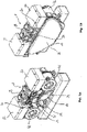
- Fig. 1b shows a rear view of the power unit, whereby it can be seen that in the variant according to Figures 1a-1d the exhaust port 24 of the cylinder head 20 is oriented toward the rear.
- a cover 28 is provided on the rear of the generator set. The cover 28 covers spur gears 34, 35 which are non-rotatably connected to the crankshafts 11, 12.
- FIG. 1c a plan view of the generator set is shown. It can be seen that the arrangement of the generators 41, 42 and the electronics housing 27 results in a particularly compact, in particular narrow construction of the power unit. In addition, the design of the cylinder head 20 can be clearly seen in the plan view.
- the cylinder head 20 has the outlet port 24 on one end face.
- the outlet connector 24 has two lumens and opens into each of the cylinders 21, 22.
- the intake connectors 23 are arranged on an opposite end face of the cylinder head 20.
- the intake manifolds 23 are arranged at a distance from one another and each open directly into the first cylinder 21 and the second cylinder 22.
- a separate intake manifold 23 is assigned to each of the cylinders 21, 22.
- the cylinder head 20 is configured essentially axially symmetrically. This has the advantage that the cylinder head 20 can be placed on the crankshaft housing 10 in two different orientations.
- the cylinder head 20 may be seated on the crankcase 10 in a 180° rotated orientation such that the exhaust stub 24 is oriented toward a front of the power plant rather than a rear.
- the power unit in which the cylinder head 20 is rotated by 180° and placed on the crankshaft housing 10.
- the components of the generator set are as per Figures 1a-1d identical to the components of the generating set according to Figures 2a-2c .
- the only difference is that the cylinder head 20 according to the assembly Figures 1a-1d compared to the assembly according to Figures 2a-2c is placed on the crankcase 10 in an orientation offset by 180°.
- a valve cover 29 that is placed on the cylinder head 20 can also be seen from above.
- Fig. 1d 12 shows the internal structure of the generator set, with the crankcase 10 and the valve cover 29 omitted for clarity.
- the generator has two crankshafts 11, 12 which are coupled to each other in phase.
- the coupling takes place via the spur gears 34, 35, which have interlocking teeth.
- the spur gears 34, 35 are arranged on a rear side of the power unit and well in accordance with the exempted representation 3 recognizable.
- a drive wheel 36, 37 sits on each spur gear 34, 35.
- Each drive wheel 36, 37 is coupled to a drive wheel of one of the generators 41, 42 via a belt or a chain.
- crankshaft 11, 12 The coupling of the crankshaft 11, 12 with the respective associated generator 41, 42 is therefore carried out via the drive wheel 36, 37 coaxially connected to the crankshaft 11, 12, a belt drive or chain drive and the drive wheel on the generator coaxially connected non-rotatably to a generator axis.
- FIG. 1d Another important aspect of the generator set is shown, which contributes to reducing the size of the generator set.
- the camshaft 30 located between the crankshafts 11,12.
- the camshaft 30 extends between the connecting rods 13 and below the cylinder head 20.
- the connecting rods 13 with the cylinder head 20 and the crankshafts 11, 12 delimit a free space that is used efficiently by the camshaft 30.
- the camshaft 30 is arranged in particular in a center line between the two crankshafts 11, 12.
- the camshaft 30 is driven via a belt drive 31.
- the belt drive 31 connects a gear wheel 39 of the second crankshaft 12 to the camshaft 30.
- the camshaft 30 has four cams 32, each of which is assigned a control rod 33.
- the control rods 33 extend from the camshaft 30 through the crankshaft housing 10 and the cylinder head 20 into the valve chamber below the valve cover 29.
- Rocker arms 26 which interact with the valves 25 are arranged in the valve chamber.
- An outer contour of the cam 32 is picked up via the control rod 33 and converted into a corresponding tilted position of the rocker arm 26 .
- a valve 25 is thus assigned to each control rod 33 .
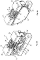
- the Figures 2a and 2b show a generator set essentially analogous to the generator set according to FIG Figures 1a, 1b is trained.
- the representation according to Figures 2a, 2b differs from the assembly according to Figures 1a, 1b by the twisted arrangement of the cylinder head 20.
- the cylinder head 20 is mounted on the crankcase 10 so that the exhaust port 24 faces the front of the generator set.
- the valve cover 29 is compared to the assembly according to FIG Fig. 1a rotated by 180°.
- the cylinder head 20 and the valve cover 29 are rotated through 180° and placed on the crankshaft housing 10 .
- Figure 2c shows the top view of the power unit during assembly according to FIG Figures 2a, 2b . According to the top view Figure 2c shows in comparison to the top view according to FIG 1c It is also clear that the cylinder head 20 can be mounted on the crankcase 10 in two different orientations.
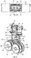
- FIG. 3 illustrates the internal structure of the two-cylinder reciprocating engine with the two crankshafts 11, 12, each having spur gears 34, 35.
- the teeth of the spur gears 34, 35 mesh and thus synchronize the movement of the pistons 18, 19.
- the pistons are guided in a tandem arrangement in the cylinders 21, 22 (not shown here). This means that the pistons 18, 19 reach their upper and lower dead centers simultaneously.
- valves 25 are provided, which can be actuated via rocker arms 26 .
- the rocker arms 26 are coupled to the four control rods 33, each of which is associated with a cam 32 of the camshaft 30.
- crankshafts 11, 12 there can also be seen that they each have a flywheel 14, 15 on the side opposite the drive wheels 36, 37.
- each flywheel has a balancing mass 16 in order to reduce vibrations during operation of the two-cylinder reciprocating engine 1 .
- At least the first flywheel 14 connected to the first crankshaft 11 has a circumferential mark 17 on it.
- a crankshaft sensor can use the circumferential marking 17 to detect the current position of the piston 18 , 19 in the cylinder 21 , 22 .
- a broadened marking indicates the top or bottom dead center of the piston 18, 19.
Landscapes
- Engineering & Computer Science (AREA)
- Chemical & Material Sciences (AREA)
- Combustion & Propulsion (AREA)
- Mechanical Engineering (AREA)
- General Engineering & Computer Science (AREA)
- Hybrid Electric Vehicles (AREA)
- Valve-Gear Or Valve Arrangements (AREA)
- Cylinder Crankcases Of Internal Combustion Engines (AREA)
- Control Of Vehicle Engines Or Engines For Specific Uses (AREA)
Description
- Die Erfindung betrifft ein Stromaggregat, insbesondere ein Stromaggregat eines Hybridfahrzeugs, sowie ein Fahrzeug mit einem derartigen Stromaggregat. Ein Stromaggregat der eingangs genannten Art ist beispielsweise aus
WO 2012/056275 A1 bekannt. - Das bekannte Stromaggregat umfasst einen Zweizylinder-Hubkolbenmotor mit zwei Kolben, die in zwei Zylindern in Tandemanordnung geführt sind. Jeder Kolben ist durch einen Pleuel mit jeweils einer Kurbelwelle verbunden. Die beiden Kurbelwellen drehen gegenläufig. Der Zweizylinder-Hubkolbenmotor umfasst ferner ein Kurbelwellengehäuse, in welchem die Kurbelwellen angeordnet sind. Ferner ist ein Generator vorgesehen, der wenigstens mit einer Kurbelwelle antriebsverbunden ist. Auf das Kurbelwellengehäuse ist ein Zylinderkopf aufgesetzt, der mit dem Kurbelwellengehäuse fest verbunden ist.
- Das vorbekannte Stromaggregat kommt vorzugsweise in einem Hybridfahrzeug zum Einsatz. Bei derartigen Hybridfahrzeugen wird ein besonders großer Bauraum für die Energiespeicherelemente, insbesondere Akkumulatoren, benötigt, so dass eine Reduktion der Baugröße des Stromaggregats wünschenswert ist. Zu berücksichtigen ist auch der gewünschte Einbauort des Stromaggregats in einem Fahrzeug. Aus Gewichtsverteilungsgründen ist es vorteilhaft, das Stromaggregat möglichst nah an eine Spritzwand des Motorraums zu platzieren. Dabei können Abgasleitungen oder Luftzuführleitungen, die am Zylinderkopf angeschlossen sind, hinderlich sein. Es besteht insofern ein Bedarf an einem Stromaggregat, das derart flexibel und platzsparend in ein Fahrzeug integrierbar ist.
- Ein weiteres Stromaggregat ist aus
WO 2012/163902 A1 bekannt. Das darin beschriebene Stromaggregat umfasst einen Zweizylinder-Hubkolbenmotor, der mittels einer Nebenwelle an einen Generator gekoppelt ist. Die Nebenwelle ist zwischen den Zylindern der Hubkolbenmotors angeordnet. An jeder Seite des Hubkolbenmotors ist jeweils eine Nockenwelle vorgesehen. Die beiden Nockenwellen sind die jeweils mit den Ventilen eines der Zylinder gekoppelt. Der Nachteil dieser Gestaltung ist es, dass durch den im Wesentlichen vor dem Hubkolbenmotor platzierten Generator die Bautiefe des Stromaggregats groß ist. Damit sind die Möglichkeiten zum Einbau des Stromaggregats in ein Fahrzeug beschränkt. - Vor diesem Hintergrund stellt sich die Aufgabe, die der vorliegenden Erfindung zugrunde liegt, ein Stromaggregat der eingangs genannten Art so zu verbessern, dass dadurch das Stromaggregat flexibel in unterschiedlichen Einbausituationen eingesetzt werden kann und dass es einen kompakten Aufbau aufweist. Eine weitere Aufgabe der Erfindung besteht darin, ein Fahrzeug mit einem solchen Stromaggregat anzugeben.
- Erfindungsgemäß wird diese Aufgabe im Hinblick auf das Stromaggregat durch den Gegenstand des Patentanspruchs 1 gelöst. Im Hinblick auf das Fahrzeug wird die Aufgabe durch den Gegenstand des Patentanspruchs 9 gelöst.
- So beruht die Erfindung auf dem Gedanken, ein Stromaggregat, insbesondere ein Stromaggregat eines Hybridfahrzeugs, mit einem Zweizylinderhubkolbenmotor anzugeben, der ein Kurbelwellengehäuse aufweist. In dem Kurbelwellengehäuse sind zwei gegenläufige Kurbelwellen angeordnet, die durch Pleuel mit zwei Kolben verbunden sind. Die Kolben sind in zwei Zylindern in Tandemanordnung geführt. Wenigstens eine Kurbelwelle ist mit einem Generator antriebsverbunden. Der Hubkolbenmotor weist einen Zylinderkopf auf, der mit dem Kurbelwellengehäuse verbunden ist. Der Hubkolbenmotor weist vorzugsweise eine untenliegende Nockenwelle auf. Der Zylinderkopf kann in wenigstens zwei, insbesondere um 180° zueinander verdrehten, Positionen mit dem Kurbelwellengehäuse verbindbar sein.
- Die Kombination aus der unten liegenden Nockenwelle und dem drehbar mit dem Kurbelwellengehäuse verbindbaren Zylinderkopf sind besondere Vorteile verbunden. Die unten liegende Nockenwelle sorgt insbesondere für eine geringe Baugröße des Stromaggregats. Der in zwei unterschiedlichen Positionen mit dem Kurbelwellengehäuse verbindbare Zylinderkopf trägt dazu insofern bei, als dass auf diese Weise die Anordnung des Stromaggregats innerhalb eines Fahrzeugs flexibel gestaltet werden kann. Somit benötigt das Stromaggregat je nach Einbausituation einen möglichst geringen Bauraum im Fahrzeug, da der verschiedenartig mit dem Kurbelwellengehäuse verbindbare Zylinderkopf eine entsprechende Leitungsführung für Luftzufuhr- oder Abgasleitungen erlaubt.
- Beispielsweise kann das Stromaggregat vergleichsweise nah an eine Spritzwand in einem Motorraum positioniert werden, da der Zylinderkopf so ausgerichtet werden kann, dass Luftansaugrohr oder Abgasrohr in Fahrtrichtung nach vorne aus dem Zylinderkopf entspringen. Damit bleibt im Motorraum ein größerer Anteil verfügbaren Volumens, der beispielsweise durch Speicherelemente genutzt werden kann. Bei einer liegenden Anordnung des Stromaggregats kann indessen eine andere Leitungsführung vorteilhaft sein. Insofern ist das Stromaggregat wegen des in verschiedenen Positionen mit dem Kurbelwellengehäuse verbindbaren Zylinderkopfs flexibel einsetzbar.
- Insbesondere ist bevorzugt vorgesehen, dass der Zylinderkopf einen symmetrischen Aufbau aufweist. Konkret können die Anschlussflächen bzw. Anschlussöffnungen im Zylinderkopf und/oder im Kurbelwellengehäuse zu einer Mittelachse des Stromaggregats achsensymmetrisch angeordnet sein, so dass die Orientierung des Zylinderkopfs gegenüber dem Kurbelwellengehäuse beliebig wählbar ist. Mit anderen Worten kann der Zylinderkopf beliebig in zwei verschiedenen Orientierungen mit dem Kurbelwellengehäuse verbunden werden, wobei gleichzeitig unabhängig von der Orientierung des Zylinderkopfs gegenüber dem Kurbelwellengehäuse die jeweiligen Anschlussöffnungen deckungsgleich sind.
- Bei der Erfindung ist vorgesehen, dass die Nockenwelle in einer Mittelebene zwischen den Kurbelwellen angeordnet ist. Insbesondere kann die Nockenwelle in der Mittelebene zwischen den Pleueln der Kolben angeordnet sein. Damit wird der zwischen den Pleueln der Kolben verfügbare Platz besonders effizient genutzt, was zur Kompaktheit des Stromaggregats beiträgt.
- Die Nockenwelle ist erfindungsgemäß unterhalb eines unteren Totpunkts der Kolben angeordnet. Dies führt ebenfalls dazu, dass das Stromaggregat besonders kompakt ausgebildet ist. Insbesondere können die Kolben näher zusammengerückt werden, ohne dass die Pleuel oder Zylinder mit der Nockenwelle kollidieren.
- Der Zylinderkopf weist vorzugsweise einen Ansaugstutzen für ein Zündgemisch und einen Auslassstutzen für Abgase auf. Der Ansaugstutzen und der Auslassstutzen sind vorzugsweise auf gegenüberliegenden Seiten des Zylinderkopfs angeordnet.
- Die Nockenwelle ist vorzugsweise über einen Riementrieb oder einen Kettentrieb mit einer der Kurbelwellen antriebsverbunden. Die Nockenwelle kann wenigstens einen Nocken aufweisen, der mit einer Steuerstange gekoppelt ist. Die Steuerstange ist vorzugsweise mit einem Kipphebel eines Ventils im Zylinderkopf wirkverbunden. Die Steuerstange überträgt die Außenkontur der Nocke auf eine Kippbewegung des Kipphebels, so dass das Ventil im Zylinderkopf anhand der Nockenkontur geöffnet und geschlossen werden kann.
- Besonders bevorzugt ist es bei der vorliegenden Erfindung, wenn die Nockenwelle mehrere, insbesondere vier, Nocken aufweist, die mit jeweils einer Steuerstange gekoppelt sind. Dabei ist bevorzugt vorgesehen, dass die Steuerstange, insbesondere alle Steuerstangen zwischen den beiden Zylindern angeordnet sind. Diese Anordnung der Steuerstangen nutzt ebenfalls sehr effizient den zwischen den Zylindern bzw. Kolben verbleibenden Freiraum, so dass dies dem kompakten Aufbau des Stromaggregats zu Gute kommt.
- Die beiden Kurbelwellen können bei einer bevorzugten Ausgestaltung der Erfindung jeweils ein verzahntes Stirnrad tragen, wobei die Stirnräder der beiden Kurbelwellen ineinander greifen und die Kurbelwellen miteinander phasengleich koppeln. Durch das Ineinandergreifen der Stirnräder der Kurbelwellen wird eine erzwungene Abhängigkeit der Bewegungen der beiden Kolben voneinander erreicht. Dies fördert den Gleichlauf des Stromaggregats.
- Vorzugsweise trägt jede Kurbelwelle ein Schwungrad mit einer Ausgleichsmasse. Dabei kann wenigstens ein Schwungrad eine Umfangsmarkierung zur Erfassung einer Kurbelwellenstellung mittels eines Kurbelwellensensors aufweisen. Konkret kann vorgesehen sein, dass eines der Schwungräder eine Außenverzahnung aufweist, wobei die Außenverzahnung im Wesentlichen gleiche Zahnabstände aufweist. Eine Ausnahme besteht an einer Stelle des Schwungradumfangs, bei welchem die Außenverzahnung beispielsweise eine längere Lücke aufweisen kann. Die längere Lücke ist vorzugsweise so angeordnet, dass sie beim Vorbeilaufen an einem entsprechenden, beispielweise optischen, Sensor zu erkennen gibt, dass sich einer der beiden Kolben an seinem unteren oder oberen Totpunkt befindet. Jedenfalls kann mittels einer solchen Markierung die Position der Kurbelwelle ermittelt und für die Regelung des Stromaggregats eingesetzt werden.
- Ein weiterer Aspekt der Erfindung betrifft ein Fahrzeug, insbesondere ein einspuriges oder mehrspuriges Hybridmotorfahrzeug, mit einem zuvor beschriebenen Stromaggregat. Bei dem Fahrzeug ist das Stromaggregat vorzugsweise im Motorraum an einer Spritzwand angeordnet, wobei die Spritzwand einen Fahrgastraum von dem Motorraum trennt. Vorteilhaft ist es, dass das Stromaggregat in zwei unterschiedlichen Orientierungen in dem Motorraum eingesetzt werden kann, wodurch sich das Stromaggregat universell für eine Vielzahl von Fahrzeugformen eignet.
- Die Erfindung wird im Folgenden anhand eines Ausführungsbeispiels unter Bezugnahme auf die beigefügten, schematischen Zeichnungen näher erläutert. Darin zeigen:
- Fig. 1a:
- eine perspektivische Vorderansicht eines erfindungsgemäßen Stromaggregats nach einem bevorzugten Ausführungsbeispiel;
- Fig. 1b:
- eine perspektivische Rückansicht des Stromaggregats gemäß
Fig. 1a ; - Fig. 1c:
- eine Draufsicht auf das Stromaggregat gemäß
Fig. 1a ; - Fig. 1d:
- eine perspektivische Vorderansicht des Stromaggregats gemäß
Fig. 1a ohne ein Kurbelwellengehäuse; - Fig. 2a:
- eine perspektivische Vorderansicht des Stromaggregats gemäß
Fig. 1a , wobei der Zylinderkopf um 180° verdreht aufgesetzt ist; - Fig. 2b:
- eine perspektivische Rückansicht des Stromaggregats gemäß
Fig. 2a ; - Fig. 2c:
- eine Draufsicht auf das Stromaggregat gemäß
Fig. 2a ; und - Fig. 3:
- eine perspektivische Rückansicht der Kolbenanordnung des Stromaggregats gemäß
Fig. 1a . - In den beigefügten Figuren ist insgesamt ein Stromaggregat, insbesondere ein Stromaggregat eines Hybridfahrzeugs, gezeigt, welches einen Zweizylinder-Hubkolbenmotor 1 aufweist. Der Zweizylinder-Hubkolbenmotor ist mit Generatoren 41, 42 mechanisch gekoppelt. Die Generatoren 41, 42 erzeugen Strom, der beispielsweise zum Laden eines Fahrakkumulators genutzt wird.
- Der Zweizylinder-Hubkolbenmotor 1 umfasst ein Kurbelwellengehäuse 10, in dem eine erste Kurbelwelle 11 und eine zweite Kurbelwelle 12 angeordnet sind. Die erste Kurbelwelle 11 und die zweite Kurbelwelle 12 sind jeweils durch Pleuel 13 mit einem ersten Kolben 18 und einem zweiten Kolben 19 verbunden. Die Kolben 18, 19 sind in Tandemanordnung in zwei Zylindern 21, 22 geführt. Die Zylinder 21, 22 sind in einem Zylinderkopf 20 angeordnet. Der Zylinderkopf 20 weist ferner zwei Ansaugstutzen 23 und einen Auslassstutzen 24 auf. Über den Ansaugstutzen 23 kann Verbrennungsluft angesaugt und an die Zylinder 21, 22 geleitet werden. In den Zylinder 21, 22 entstehende Abgase werden über den Auslassstutzen 24 ausgeleitet.
- Wie in
Fig. 1a gut erkennbar ist, sind seitlich neben dem Zweizylinder-Hubkolbenmotor 1 die Generatoren 41, 42 angeordnet. Insbesondere ist der Zweizylinder-Hubkolbenmotor 1 im Wesentlichen zwischen den beiden Generatoren 41, 42 angeordnet. Die Generatoren 41, 42 sind insbesondere in einer Linie mit dem Zweizylinder-Hubkolbenmotor 1 ausgerichtet, wodurch sich eine besonders schmale Bauweise des Stromaggregats ergibt. - Auf Höhe des Zylinderkopfs 20 sind beidseitig am Zweizylinder-Hubkolbenmotor 1 Elektronikgehäuse 27 vorgesehen, die eine Leistungselektronik enthalten können. Die Elektronikgehäuse sind jeweils oberhalb eines Generators 41, 42 angeordnet. Die in den Elektronikgehäusen 27 angeordneten Leistungselektroniken können jeweils elektrisch mit einem der Generatoren 41, 42 verbunden sein.
-
Fig. 1b zeigt eine Rückansicht des Stromaggregats, wobei erkennbar ist, dass bei der Variante gemäßFig. 1a-1d der Auslassstutzen 24 des Zylinderkopfs 20 zur Rückseite ausgerichtet ist. Auf der Rückseite des Stromaggregats ist eine Abdeckung 28 vorgesehen. Die Abdeckung 28 deckt Stirnräder 34, 35 ab, die drehfest mit den Kurbelwellen 11, 12 verbunden sind. - In
Fig. 1c ist eine Draufsicht auf das Stromaggregat gezeigt. Es ist erkennbar, dass durch die Anordnung der Generatoren 41, 42 und der Elektronikgehäuse 27 eine besonders kompakte, insbesondere schmale Bauweise des Stromaggregats erreicht wird. Außerdem ist in der Draufsicht die Gestaltung des Zylinderkopfs 20 gut erkennbar. - Der Zylinderkopf 20 weist auf einer Stirnseite den Auslassstutzen 24 auf. Der Auslassstutzen 24 ist zweilumig ausgeführt und mündet in jeden der Zylinder 21, 22. Auf einer gegenüberliegenden Stirnseite des Zylinderkopfs 20 sind die Ansaugstutzen 23 angeordnet. Die Ansaugstutzen 23 sind voneinander beabstandet angeordnet und münden jeweils direkt in den ersten Zylinder 21 bzw. den zweiten Zylinder 22. Jedem der Zylinder 21, 22 ist ein separater Ansaugstutzen 23 zugeordnet.
- Im Übrigen ist in der Draufsicht gemäß
Fig. 1c erkennbar, dass bezogen auf eine in der Zeichnungsebene vertikale Symmetrieachse der Zylinderkopf 20 im Wesentlichen achsensymmetrisch ausgebildet ist. Das hat den Vorteil, dass der Zylinderkopf 20 in zwei unterschiedlichen Orientierungen auf das Kurbelwellengehäuse 10 aufgesetzt werden kann. Insbesondere kann der Zylinderkopf 20 in einer um 180° verdrehten Orientierung auf das Kurbelwellengehäuse 10 aufgesetzt werden, so dass der Abgasstutzen 24 anstatt zu einer Rückseite, zu einer Vorderseite des Stromaggregats ausgerichtet ist. - In den
Figuren 2a-2c ist das Stromaggregat erkennbar, bei dem der Zylinderkopf 20 um 180° verdreht auf das Kurbelwellengehäuse 10 aufgesetzt ist. Im Wesentlichen sind die Bauteile des Stromaggregats gemäßFiguren 1a-1d identisch zu den Bauteilen des Stromaggregats gemäßFiguren 2a-2c . Der Unterschied besteht lediglich darin, dass der Zylinderkopf 20 bei dem Zusammenbau gemäßFiguren 1a-1d gegenüber dem Zusammenbau gemäßFiguren 2a-2c in um 180° versetzter Orientierung auf das Kurbelwellengehäuse 10 aufgesetzt ist. - In
Fig. 1c ist von oben zusätzlich ein Ventildeckel 29 erkennbar, der auf den Zylinderkopf 20 aufgesetzt ist.Fig. 1d zeigt hingegen den inneren Aufbau des Stromaggregats, wobei zur Verdeutlichung das Kurbelwellengehäuse 10 und der Ventildeckel 29 weggelassen wurden. - Wie in
Fig. 1d gut erkennbar ist, weist das Stromaggregat zwei Kurbelwellen 11, 12 auf, die phasengleich miteinander gekoppelt sind. Die Kopplung erfolgt über die Stirnräder 34, 35, die eine ineinandergreifende Verzahnung aufweisen. Die Stirnräder 34, 35 sind auf einer Rückseite des Stromaggregats angeordnet und gut in der freigestellten Darstellung gemäßFig. 3 erkennbar. Auf jedem Stirnrad 34, 35 sitzt ein Treibrad 36, 37. Jedes Treibrad 36, 37 ist über einen Riemen oder eine Kette mit einem Antriebsrad eines der Generatoren 41, 42 gekoppelt. Die Kopplung der Kurbelwelle 11, 12 mit dem jeweilig zugeordneten Generator 41, 42 erfolgt also über das koaxial mit der Kurbelwelle 11, 12 verbundene Treibrad 36, 37, einen Riementrieb oder Kettentrieb und das koaxial mit einer Generatorachse drehfest verbundene Antriebsrad am Generator. - In
Fig. 1d ist ein weiterer wesentlicher Aspekt des Stromaggregats gezeigt, der zur Reduktion der Baugröße des Stromaggregats beiträgt. Konkret zeigtFig. 1d die Nockenwelle 30, die sich zwischen den Kurbelwellen 11, 12 befindet. Insbesondere erstreckt sich die Nockenwelle 30 zwischen den Pleueln 13 und unterhalb des Zylinderkopfs 20. Konkret begrenzen die Pleuel 13 mit dem Zylinderkopf 20 und den Kurbelwellen 11, 12 einen Freiraum, der effizient durch die Nockenwelle 30 genutzt wird. Die Nockenwelle 30 ist insbesondere in einer Mittellinie zwischen den beiden Kurbelwellen 11, 12 angeordnet. Der Antrieb der Nockenwelle 30 erfolgt über einen Riementrieb 31. Der Riementrieb 31 verbindet ein Zahnrad 39 der zweiten Kurbelwelle 12 mit der Nockenwelle 30. - Die Nockenwelle 30 weist bei dem dargestellten Ausführungsbeispiel vier Nocken 32 auf, welchen jeweils eine Steuerstange 33 zugeordnet ist. Die Steuerstangen 33 erstrecken sich von der Nockenwelle 30 durch das Kurbelwellengehäuse 10 und den Zylinderkopf 20 bis in den Ventilraum unterhalb des Ventildeckels 29. Im Ventilraum sind Kipphebel 26 angeordnet, die mit den Ventilen 25 zusammenwirken. So wird über die Steuerstange 33 eine Außenkontur des Nockens 32 abgegriffen und in eine entsprechende Kippstellung des Kipphebels 26 umgewandelt. Bei dem hier dargestellten Ausführungsbeispiel ist es bevorzugt, wenn insgesamt vier Ventile vorgesehen sind. Jeder Steuerstange 33 ist somit ein Ventil 25 zugeordnet.
- Die
Figuren 2a und 2b zeigen ein Stromaggregat, das im Wesentlichen analog zum Stromaggregat gemäßFig. 1a, 1b ausgebildet ist. Jedenfalls die einzelnen Bauteile sind identisch. Die Darstellung gemäßFiguren 2a, 2b unterscheidet sich von dem Zusammenbau gemäßFig. 1a, 1b durch die verdrehte Anordnung des Zylinderkopfs 20. InFig. 2a ist erkennbar, dass im Unterschied zu der Anordnung gemäßFig. 1a , der Zylinderkopf 20 so auf dem Kurbelgehäuse 10 montiert ist, dass der Auslassstutzen 24 zur Vorderseite des Stromaggregats gerichtet ist. Ebenso ist der Ventildeckel 29 gegenüber dem Zusammenbau gemäßFig. 1a um 180° verdreht aufgesetzt. Dasselbe gilt im Wesentlichen für die Darstellung gemäßFig. 2b , bei der gegenüber der Darstellung gemäßFig. 1b erkennbar ist, dass der Zylinderkopf 20 und der Ventildeckel 29 um 180° verdreht auf das Kurbelwellengehäuse 10 aufgesetzt ist. -
Fig. 2c zeigt die Draufsicht auf das Stromaggregat bei dem Zusammenbau gemäßFiguren 2a, 2b . Die Draufsicht gemäßFig. 2c zeigt im Vergleich zu der Draufsicht gemäßFig. 1c ebenfalls deutlich, dass der Zylinderkopf 20 in zwei verschiedenen Orientierung auf das Kurbelwellengehäuse 10 montiert werden kann. -
Fig. 3 verdeutlicht den inneren Aufbau des Zweizylinder-Hubkolbenmotors mit den beiden Kurbelwellen 11, 12, die jeweils Stirnräder 34, 35 aufweisen. Die Stirnräder 34, 35 greifen mit ihrer Verzahnung ineinander und synchronisieren so die Bewegung der Kolben 18, 19. Die Kolben sind in den hier nicht dargestellten Zylindern 21, 22 in Tandemanordnung geführt. Das bedeutet, dass die Kolben 18, 19 gleichzeitig ihren oberen bzw. unteren Totpunkt erreichen. - In
Fig. 3 ist ebenfalls erkennbar, dass insgesamt vier Ventile 25 vorgesehen sind, die über Kipphebel 26 betätigbar sind. Die Kipphebel 26 sind mit den vier Steuerstangen 33 gekoppelt, denen jeweils ein Nocken 32 der Nockenwelle 30 zugeordnet ist. - Hinsichtlich der Kurbelwellen 11, 12 ist außerdem erkennbar, dass diese auf der den Treibrädern 36, 37 gegenüberliegenden Seiten jeweils ein Schwungrad 14, 15 aufweisen. Dabei weist jedes Schwungrad eine Ausgleichsmasse 16 auf, um Schwingungen beim Betrieb des Zweizylinder-Hubkolbenmotors 1 zu reduzieren. Wenigstens das erste Schwungrad 14, das mit der ersten Kurbelwelle 11 verbunden ist, weist eine Umfangsmarkierung 17 auf. Anhand der Umfangsmarkierung 17 kann ein Kurbelwellensensor die aktuelle Position des Kolbens 18, 19 im Zylinder 21, 22 erfassen. Eine verbreiterte Markierung zeigt dabei den oberen oder unteren Totpunkt des Kolbens 18, 19 an.
- Aus den beigefügten Zeichnungen ist erkennbar, dass durch die Möglichkeit, den Zylinderkopf 20 in unterschiedlichen Orientierungen auf das Kurbelgehäuse 10 zu setzen, die Einbausituation für das Stromaggregat individuell anpassbar ist. Gleichzeitig bewirkt die untenliegende Nockenwelle 30 einen besonders kompakten Aufbau des Stromaggregats. Insgesamt kann so der notwendige Bauraum in einem Fahrzeug reduziert werden.
-
- 1
- Zweizylinder-Hubkolbenmotor
- 10
- Kurbelwellengehäuse
- 11
- erste Kurbelwelle
- 12
- zweite Kurbelwelle
- 13
- Pleuel
- 14
- erste Schwungrad
- 15
- zweites Schwungrad
- 16
- Ausgleichsmasse
- 17
- Umfangsmarkierung
- 18
- erster Kolben
- 19
- zweiter Kolben
- 20
- Zylinderkopf
- 21
- erster Zylinder
- 22
- zweiter Zylinder
- 23
- Ansaugstutzen
- 24
- Auslassstutzen
- 25
- Ventil
- 26
- Kipphebel
- 27
- Elektronikgehäuse
- 28
- Abdeckung
- 29
- Ventildeckel
- 30
- Nockenwelle
- 31
- Riementrieb
- 32
- Nocken
- 33
- Steuerstange
- 34
- erstes Stirnrad
- 35
- zweites Stirnrad
- 36
- erstes Treibrad
- 37
- zweites Treibrad
- 39
- Zahnrad
- 41
- erster Generator
- 42
- zweiter Generator
Claims (9)
- Stromaggregat, insbesondere Stromaggregat eines Hybridfahrzeugs, mit einem Zweizylinder-Hubkolbenmotor (1), der ein Kurbelwellengehäuse (10) aufweist, in dem zwei gegenläufige Kurbelwellen (11, 12) angeordnet sind, die durch Pleuel (13) mit Kolben (18, 19) verbunden sind, welche in zwei Zylindern (21, 22) in Tandem-Anordnung geführt sind, wobei beide Kurbelwellen (11, 12) jeweils mit einem Generator (41, 42) antriebsverbunden sind, und wobei der Hubkolbenmotor (1) einen Zylinderkopf (20) aufweist, der mit dem Kurbelwellengehäuse (10) verbunden ist,
dadurch gekennzeichnet, dass
der Hubkolbenmotor (1) eine untenliegende Nockenwelle (30) aufweist und der Zylinderkopf (20) in wenigstens zwei, insbesondere um 180° zueinander verdrehten, Positionen mit dem Kurbelwellengehäuse (10) verbindbar ist, wobei die Nockenwelle (30) in einer Mittelebene zwischen den Kurbelwellen (11, 12) unterhalb eines unteren Totpunkts der beiden Kolben (18, 19) angeordnet ist. - Stromaggregat nach dem vorhergehenden Anspruch
dadurch gekennzeichnet, dassder Zylinderkopf (20) einen Ansaugstutzen (23) für ein Zündgemisch undeinen Auslassstutzen (24) für Abgase aufweist, wobei der Ansaugstutzen (23) und der Auslassstutzen (24) auf unterschiedlichen Seiten des Zylinderkopfs (20) angeordnet sind. - Stromaggregat nach einem der vorhergehenden Ansprüche,
dadurch gekennzeichnet, dass
die Nockenwelle (30) über einen Riementrieb (31) oder Kettentrieb mit einer der Kurbelwellen (11, 12) antriebsverbunden ist. - Stromaggregat nach einem der vorhergehenden Ansprüche,
dadurch gekennzeichnet, dass
die Nockenwelle (30) wenigstens einen Nocken (32) aufweist, der mit einer Steuerstange (33) gekoppelt ist, die mit einem Kipphebel (26) eines Ventils (25) im Zylinderkopf (20) wirkverbunden ist. - Stromaggregat nach Anspruch 4,
dadurch gekennzeichnet, dass
die Nockenwelle (30) mehrere, insbesondere vier, Nocken (32) aufweist, die mit jeweils einer Steuerstange (33) gekoppelt sind. - Stromaggregat nach Anspruch 4 oder 5,
dadurch gekennzeichnet, dass
die Steuerstange (33), insbesondere alle Steuerstangen (33), zwischen den beiden Zylindern (21, 22) angeordnet ist/sind. - Stromaggregat nach einem der vorhergehenden Ansprüche,
dadurch gekennzeichnet, dass
die beiden Kurbelwellen (11, 12) jeweils ein verzahntes Stirnrad (34, 35) tragen, wobei die Stirnräder (34, 35) der beiden Kurbelwellen (11, 12) ineinandergreifen und die Kurbelwellen (11, 12) miteinander phasengleich koppeln. - Stromaggregat nach einem der vorhergehenden Ansprüche,
dadurch gekennzeichnet, dass
jede Kurbelwelle (11, 12) ein Schwungrad (14, 15) mit einer Ausgleichsmasse (16) trägt, wobei wenigstens ein Schwungrad (14) eine Umfangsmarkierung (17) zur Erfassung einer Kurbelwellenstellung mittels eines Kurbelwellensensors aufweist. - Fahrzeug, insbesondere einspuriges oder mehrspuriges Hybridmotorfahrzeug, mit einem Stromaggregat nach einem der vorhergehenden Ansprüche.
Applications Claiming Priority (2)
| Application Number | Priority Date | Filing Date | Title |
|---|---|---|---|
| DE102016102048.6A DE102016102048B4 (de) | 2016-02-05 | 2016-02-05 | Stromaggregat |
| PCT/EP2017/052508 WO2017134294A1 (de) | 2016-02-05 | 2017-02-06 | Stromaggregat |
Publications (2)
| Publication Number | Publication Date |
|---|---|
| EP3411584A1 EP3411584A1 (de) | 2018-12-12 |
| EP3411584B1 true EP3411584B1 (de) | 2022-06-08 |
Family
ID=57963237
Family Applications (1)
| Application Number | Title | Priority Date | Filing Date |
|---|---|---|---|
| EP17703152.3A Active EP3411584B1 (de) | 2016-02-05 | 2017-02-06 | Stromaggregat |
Country Status (7)
| Country | Link |
|---|---|
| US (1) | US10844783B2 (de) |
| EP (1) | EP3411584B1 (de) |
| JP (1) | JP6770078B2 (de) |
| KR (1) | KR102181736B1 (de) |
| CN (1) | CN108474319B (de) |
| DE (1) | DE102016102048B4 (de) |
| WO (1) | WO2017134294A1 (de) |
Families Citing this family (2)
| Publication number | Priority date | Publication date | Assignee | Title |
|---|---|---|---|---|
| DE102020001432B3 (de) * | 2020-03-05 | 2021-03-25 | Obrist Technologies Gmbh | Stromaggregat |
| DE102020118076A1 (de) | 2020-07-09 | 2022-01-13 | Bayerische Motoren Werke Aktiengesellschaft | Maschinenkombination mit Verbrennungskraftmaschine und Generator |
Citations (1)
| Publication number | Priority date | Publication date | Assignee | Title |
|---|---|---|---|---|
| DE102010025002A1 (de) * | 2010-06-24 | 2011-12-29 | Fev Motorentechnik Gmbh | Arbeitsmaschine |
Family Cites Families (21)
| Publication number | Priority date | Publication date | Assignee | Title |
|---|---|---|---|---|
| GB324409A (en) * | 1928-10-27 | 1930-01-27 | Harry Ralph Ricardo | Improvements in valve gear for internal combustion engines |
| GB324410A (en) * | 1928-10-27 | 1930-01-27 | Harry Ralph Ricardo | Improvements in or relating to petrol-electric road vehicles |
| GB463278A (en) | 1935-11-13 | 1937-03-25 | Ariel Motors J S Ltd | Improvements relating to internal combustion engines |
| FR915993A (fr) * | 1942-05-22 | 1946-11-22 | United Aircraft Corp | Perfectionnements aux culasses pour moteurs à combustion interne et à refroidissement par l'air |
| GB584215A (en) | 1944-12-15 | 1947-01-09 | Birmingham Small Arms Co Ltd | Improvements in or relating to internal combustion engines having twin cylinders with parallel axes |
| US2596410A (en) * | 1947-12-26 | 1952-05-13 | Le Grand L Jordan | Internal-combustion engine |
| JPS5217107A (en) * | 1975-07-30 | 1977-02-08 | Nissan Motor Co Ltd | Engine |
| JPH0672546B2 (ja) * | 1986-10-14 | 1994-09-14 | 本田技研工業株式会社 | 汎用二気筒エンジン |
| DE19542758A1 (de) | 1994-11-23 | 1996-05-30 | Luk Lamellen & Kupplungsbau | Topf-Schwungrad |
| US6280158B1 (en) | 1999-01-19 | 2001-08-28 | Honda Giken Kogyo Kabushiki Kaisha | Water pump for circulating cooling water in an internal combustion engine and camshaft mounting structure therefor |
| JP4201417B2 (ja) * | 1999-01-19 | 2008-12-24 | 本田技研工業株式会社 | カムシャフトの取付構造 |
| US20050051115A1 (en) * | 2003-07-09 | 2005-03-10 | Urs Wenger | Engine with rotatable cylinder head assembly |
| MXPA06008097A (es) * | 2004-01-17 | 2007-03-21 | Optimum Power Technology Lp | Metodo para arrancar un motor. |
| DE102004041958B4 (de) | 2004-08-31 | 2017-01-19 | Deutz Ag | Hubkolbenbrennkraftmaschine mit 2- oder 4-Ventilzylinderkopf |
| DE102005048561A1 (de) | 2005-10-11 | 2007-04-12 | Bayerische Motoren Werke Ag | Zylinderkopf für eine Brennkraftmaschine |
| CN200978717Y (zh) * | 2006-03-14 | 2007-11-21 | 陆懋增 | 一种双缸v型柴油机 |
| CN1928328A (zh) * | 2006-09-18 | 2007-03-14 | 陈维加 | 便携式发电机的发动机装置 |
| JP2008255971A (ja) * | 2007-04-09 | 2008-10-23 | Hino Motors Ltd | 回転検出装置 |
| CH703972A1 (de) * | 2010-10-29 | 2012-04-30 | Obrist Engineering Gmbh | Verbrennungskraftmaschine. |
| AT511552B1 (de) * | 2011-05-30 | 2015-02-15 | Avl List Gmbh | Stromerzeuger für ein kraftfahrzeug |
| JP6199102B2 (ja) * | 2013-07-19 | 2017-09-20 | 本田技研工業株式会社 | エンジン発電機 |
-
2016
- 2016-02-05 DE DE102016102048.6A patent/DE102016102048B4/de active Active
-
2017
- 2017-02-06 CN CN201780007608.9A patent/CN108474319B/zh active Active
- 2017-02-06 JP JP2018540111A patent/JP6770078B2/ja active Active
- 2017-02-06 US US16/073,220 patent/US10844783B2/en active Active
- 2017-02-06 KR KR1020187020842A patent/KR102181736B1/ko active Active
- 2017-02-06 WO PCT/EP2017/052508 patent/WO2017134294A1/de not_active Ceased
- 2017-02-06 EP EP17703152.3A patent/EP3411584B1/de active Active
Patent Citations (1)
| Publication number | Priority date | Publication date | Assignee | Title |
|---|---|---|---|---|
| DE102010025002A1 (de) * | 2010-06-24 | 2011-12-29 | Fev Motorentechnik Gmbh | Arbeitsmaschine |
Also Published As
| Publication number | Publication date |
|---|---|
| CN108474319B (zh) | 2021-07-30 |
| CN108474319A (zh) | 2018-08-31 |
| US10844783B2 (en) | 2020-11-24 |
| JP6770078B2 (ja) | 2020-10-14 |
| JP2019505437A (ja) | 2019-02-28 |
| DE102016102048B4 (de) | 2022-02-17 |
| KR20180105651A (ko) | 2018-09-28 |
| DE102016102048A1 (de) | 2017-08-10 |
| US20190032554A1 (en) | 2019-01-31 |
| KR102181736B1 (ko) | 2020-11-24 |
| EP3411584A1 (de) | 2018-12-12 |
| WO2017134294A1 (de) | 2017-08-10 |
Similar Documents
| Publication | Publication Date | Title |
|---|---|---|
| EP3025041B1 (de) | Stromaggregat | |
| DE3231988C2 (de) | ||
| DE3612641A1 (de) | Brennkraftmaschine der v-bauart mit mittig angeordneten, zwei obenliegende nockenwellen koppelnden antriebsraedern | |
| DE3007746A1 (de) | Brennkraftmaschine | |
| DE102015122794B4 (de) | Freikolbenlineargenerator | |
| DE3540899A1 (de) | Ausbildung eines v-motors, mit jeweils zwei obenliegenden, austauschbaren ansaug- und auslassnockenwellen | |
| DE102012203701B4 (de) | Abgasturboladermodul und damit ausgerüstete Brennkraftmaschine | |
| DE102016102048B4 (de) | Stromaggregat | |
| DE102007013651A1 (de) | Brennkraftmaschine mit Aufladung | |
| DE202015106690U1 (de) | Einteiliger Nockenwellendeckel und -Träger aus Verbundmaterial | |
| DE602004005114T2 (de) | Reihenbrennkraftmaschine | |
| DE102010016356A1 (de) | Verbrennungskraftmaschine mit Kraftstoffpumpe | |
| DE102015210597A1 (de) | Hubkolbenmotor und Kraftfahrzeug | |
| DE2943560C2 (de) | Vorrichtung für einen Verbrennungsmotor | |
| DE102019112540B4 (de) | Zweiventil-pro-zylinder-schubstangen-ventiltrieb-verbrennungssystem mit direkter kraftstoffeinspritzung für einen verbrennungsmotor | |
| DE102006013940A1 (de) | V-Motor mit drehbaren Zylinderköpfen | |
| DE102020122675A1 (de) | Stromaggregat zur Anordnung in einem Frontbereich eines Hybridfahrzeugs | |
| DE202021100494U1 (de) | Kurbelwelle mit mindestens einem Gegengewicht | |
| DE102011119884B4 (de) | Motorbaugruppe mit einer Anordnung mit modifizierter Einlassöffnung | |
| DE102024109705A1 (de) | Stromaggregat | |
| DE102011107225A1 (de) | Brennkraftmaschine | |
| DE102019125705B4 (de) | Lufteinlassstruktur für einen v-motor | |
| DE102018207512A1 (de) | Antriebsvorrichtung | |
| DE102017128572B4 (de) | Verbrennungsmotor mit Drehventilen für den Gaswechsel | |
| DE102020118076A1 (de) | Maschinenkombination mit Verbrennungskraftmaschine und Generator |
Legal Events
| Date | Code | Title | Description |
|---|---|---|---|
| STAA | Information on the status of an ep patent application or granted ep patent |
Free format text: STATUS: UNKNOWN |
|
| STAA | Information on the status of an ep patent application or granted ep patent |
Free format text: STATUS: THE INTERNATIONAL PUBLICATION HAS BEEN MADE |
|
| PUAI | Public reference made under article 153(3) epc to a published international application that has entered the european phase |
Free format text: ORIGINAL CODE: 0009012 |
|
| STAA | Information on the status of an ep patent application or granted ep patent |
Free format text: STATUS: REQUEST FOR EXAMINATION WAS MADE |
|
| 17P | Request for examination filed |
Effective date: 20180619 |
|
| AK | Designated contracting states |
Kind code of ref document: A1 Designated state(s): AL AT BE BG CH CY CZ DE DK EE ES FI FR GB GR HR HU IE IS IT LI LT LU LV MC MK MT NL NO PL PT RO RS SE SI SK SM TR |
|
| AX | Request for extension of the european patent |
Extension state: BA ME |
|
| DAV | Request for validation of the european patent (deleted) | ||
| DAX | Request for extension of the european patent (deleted) | ||
| STAA | Information on the status of an ep patent application or granted ep patent |
Free format text: STATUS: EXAMINATION IS IN PROGRESS |
|
| 17Q | First examination report despatched |
Effective date: 20200728 |
|
| GRAP | Despatch of communication of intention to grant a patent |
Free format text: ORIGINAL CODE: EPIDOSNIGR1 |
|
| STAA | Information on the status of an ep patent application or granted ep patent |
Free format text: STATUS: GRANT OF PATENT IS INTENDED |
|
| INTG | Intention to grant announced |
Effective date: 20220111 |
|
| GRAS | Grant fee paid |
Free format text: ORIGINAL CODE: EPIDOSNIGR3 |
|
| GRAA | (expected) grant |
Free format text: ORIGINAL CODE: 0009210 |
|
| STAA | Information on the status of an ep patent application or granted ep patent |
Free format text: STATUS: THE PATENT HAS BEEN GRANTED |
|
| AK | Designated contracting states |
Kind code of ref document: B1 Designated state(s): AL AT BE BG CH CY CZ DE DK EE ES FI FR GB GR HR HU IE IS IT LI LT LU LV MC MK MT NL NO PL PT RO RS SE SI SK SM TR |
|
| REG | Reference to a national code |
Ref country code: AT Ref legal event code: REF Ref document number: 1497076 Country of ref document: AT Kind code of ref document: T Effective date: 20220615 Ref country code: CH Ref legal event code: EP |
|
| REG | Reference to a national code |
Ref country code: DE Ref legal event code: R096 Ref document number: 502017013279 Country of ref document: DE |
|
| REG | Reference to a national code |
Ref country code: IE Ref legal event code: FG4D Free format text: LANGUAGE OF EP DOCUMENT: GERMAN |
|
| REG | Reference to a national code |
Ref country code: LT Ref legal event code: MG9D |
|
| REG | Reference to a national code |
Ref country code: NL Ref legal event code: MP Effective date: 20220608 |
|
| PG25 | Lapsed in a contracting state [announced via postgrant information from national office to epo] |
Ref country code: SE Free format text: LAPSE BECAUSE OF FAILURE TO SUBMIT A TRANSLATION OF THE DESCRIPTION OR TO PAY THE FEE WITHIN THE PRESCRIBED TIME-LIMIT Effective date: 20220608 Ref country code: NO Free format text: LAPSE BECAUSE OF FAILURE TO SUBMIT A TRANSLATION OF THE DESCRIPTION OR TO PAY THE FEE WITHIN THE PRESCRIBED TIME-LIMIT Effective date: 20220908 Ref country code: LT Free format text: LAPSE BECAUSE OF FAILURE TO SUBMIT A TRANSLATION OF THE DESCRIPTION OR TO PAY THE FEE WITHIN THE PRESCRIBED TIME-LIMIT Effective date: 20220608 Ref country code: HR Free format text: LAPSE BECAUSE OF FAILURE TO SUBMIT A TRANSLATION OF THE DESCRIPTION OR TO PAY THE FEE WITHIN THE PRESCRIBED TIME-LIMIT Effective date: 20220608 Ref country code: GR Free format text: LAPSE BECAUSE OF FAILURE TO SUBMIT A TRANSLATION OF THE DESCRIPTION OR TO PAY THE FEE WITHIN THE PRESCRIBED TIME-LIMIT Effective date: 20220909 Ref country code: FI Free format text: LAPSE BECAUSE OF FAILURE TO SUBMIT A TRANSLATION OF THE DESCRIPTION OR TO PAY THE FEE WITHIN THE PRESCRIBED TIME-LIMIT Effective date: 20220608 Ref country code: ES Free format text: LAPSE BECAUSE OF FAILURE TO SUBMIT A TRANSLATION OF THE DESCRIPTION OR TO PAY THE FEE WITHIN THE PRESCRIBED TIME-LIMIT Effective date: 20220608 Ref country code: BG Free format text: LAPSE BECAUSE OF FAILURE TO SUBMIT A TRANSLATION OF THE DESCRIPTION OR TO PAY THE FEE WITHIN THE PRESCRIBED TIME-LIMIT Effective date: 20220908 |
|
| PG25 | Lapsed in a contracting state [announced via postgrant information from national office to epo] |
Ref country code: RS Free format text: LAPSE BECAUSE OF FAILURE TO SUBMIT A TRANSLATION OF THE DESCRIPTION OR TO PAY THE FEE WITHIN THE PRESCRIBED TIME-LIMIT Effective date: 20220608 Ref country code: LV Free format text: LAPSE BECAUSE OF FAILURE TO SUBMIT A TRANSLATION OF THE DESCRIPTION OR TO PAY THE FEE WITHIN THE PRESCRIBED TIME-LIMIT Effective date: 20220608 |
|
| PG25 | Lapsed in a contracting state [announced via postgrant information from national office to epo] |
Ref country code: NL Free format text: LAPSE BECAUSE OF FAILURE TO SUBMIT A TRANSLATION OF THE DESCRIPTION OR TO PAY THE FEE WITHIN THE PRESCRIBED TIME-LIMIT Effective date: 20220608 |
|
| PG25 | Lapsed in a contracting state [announced via postgrant information from national office to epo] |
Ref country code: SM Free format text: LAPSE BECAUSE OF FAILURE TO SUBMIT A TRANSLATION OF THE DESCRIPTION OR TO PAY THE FEE WITHIN THE PRESCRIBED TIME-LIMIT Effective date: 20220608 Ref country code: SK Free format text: LAPSE BECAUSE OF FAILURE TO SUBMIT A TRANSLATION OF THE DESCRIPTION OR TO PAY THE FEE WITHIN THE PRESCRIBED TIME-LIMIT Effective date: 20220608 Ref country code: RO Free format text: LAPSE BECAUSE OF FAILURE TO SUBMIT A TRANSLATION OF THE DESCRIPTION OR TO PAY THE FEE WITHIN THE PRESCRIBED TIME-LIMIT Effective date: 20220608 Ref country code: PT Free format text: LAPSE BECAUSE OF FAILURE TO SUBMIT A TRANSLATION OF THE DESCRIPTION OR TO PAY THE FEE WITHIN THE PRESCRIBED TIME-LIMIT Effective date: 20221010 Ref country code: EE Free format text: LAPSE BECAUSE OF FAILURE TO SUBMIT A TRANSLATION OF THE DESCRIPTION OR TO PAY THE FEE WITHIN THE PRESCRIBED TIME-LIMIT Effective date: 20220608 Ref country code: CZ Free format text: LAPSE BECAUSE OF FAILURE TO SUBMIT A TRANSLATION OF THE DESCRIPTION OR TO PAY THE FEE WITHIN THE PRESCRIBED TIME-LIMIT Effective date: 20220608 |
|
| PG25 | Lapsed in a contracting state [announced via postgrant information from national office to epo] |
Ref country code: PL Free format text: LAPSE BECAUSE OF FAILURE TO SUBMIT A TRANSLATION OF THE DESCRIPTION OR TO PAY THE FEE WITHIN THE PRESCRIBED TIME-LIMIT Effective date: 20220608 Ref country code: IS Free format text: LAPSE BECAUSE OF FAILURE TO SUBMIT A TRANSLATION OF THE DESCRIPTION OR TO PAY THE FEE WITHIN THE PRESCRIBED TIME-LIMIT Effective date: 20221008 |
|
| REG | Reference to a national code |
Ref country code: DE Ref legal event code: R097 Ref document number: 502017013279 Country of ref document: DE |
|
| PG25 | Lapsed in a contracting state [announced via postgrant information from national office to epo] |
Ref country code: AL Free format text: LAPSE BECAUSE OF FAILURE TO SUBMIT A TRANSLATION OF THE DESCRIPTION OR TO PAY THE FEE WITHIN THE PRESCRIBED TIME-LIMIT Effective date: 20220608 |
|
| PLBE | No opposition filed within time limit |
Free format text: ORIGINAL CODE: 0009261 |
|
| STAA | Information on the status of an ep patent application or granted ep patent |
Free format text: STATUS: NO OPPOSITION FILED WITHIN TIME LIMIT |
|
| PG25 | Lapsed in a contracting state [announced via postgrant information from national office to epo] |
Ref country code: DK Free format text: LAPSE BECAUSE OF FAILURE TO SUBMIT A TRANSLATION OF THE DESCRIPTION OR TO PAY THE FEE WITHIN THE PRESCRIBED TIME-LIMIT Effective date: 20220608 |
|
| 26N | No opposition filed |
Effective date: 20230310 |
|
| PG25 | Lapsed in a contracting state [announced via postgrant information from national office to epo] |
Ref country code: SI Free format text: LAPSE BECAUSE OF FAILURE TO SUBMIT A TRANSLATION OF THE DESCRIPTION OR TO PAY THE FEE WITHIN THE PRESCRIBED TIME-LIMIT Effective date: 20220608 |
|
| PG25 | Lapsed in a contracting state [announced via postgrant information from national office to epo] |
Ref country code: MC Free format text: LAPSE BECAUSE OF FAILURE TO SUBMIT A TRANSLATION OF THE DESCRIPTION OR TO PAY THE FEE WITHIN THE PRESCRIBED TIME-LIMIT Effective date: 20220608 |
|
| REG | Reference to a national code |
Ref country code: CH Ref legal event code: PL |
|
| REG | Reference to a national code |
Ref country code: BE Ref legal event code: MM Effective date: 20230228 |
|
| GBPC | Gb: european patent ceased through non-payment of renewal fee |
Effective date: 20230206 |
|
| PG25 | Lapsed in a contracting state [announced via postgrant information from national office to epo] |
Ref country code: LU Free format text: LAPSE BECAUSE OF NON-PAYMENT OF DUE FEES Effective date: 20230206 Ref country code: LI Free format text: LAPSE BECAUSE OF NON-PAYMENT OF DUE FEES Effective date: 20230228 Ref country code: CH Free format text: LAPSE BECAUSE OF NON-PAYMENT OF DUE FEES Effective date: 20230228 |
|
| REG | Reference to a national code |
Ref country code: IE Ref legal event code: MM4A |
|
| PG25 | Lapsed in a contracting state [announced via postgrant information from national office to epo] |
Ref country code: GB Free format text: LAPSE BECAUSE OF NON-PAYMENT OF DUE FEES Effective date: 20230206 |
|
| PG25 | Lapsed in a contracting state [announced via postgrant information from national office to epo] |
Ref country code: IT Free format text: LAPSE BECAUSE OF FAILURE TO SUBMIT A TRANSLATION OF THE DESCRIPTION OR TO PAY THE FEE WITHIN THE PRESCRIBED TIME-LIMIT Effective date: 20220608 Ref country code: IE Free format text: LAPSE BECAUSE OF NON-PAYMENT OF DUE FEES Effective date: 20230206 Ref country code: GB Free format text: LAPSE BECAUSE OF NON-PAYMENT OF DUE FEES Effective date: 20230206 Ref country code: FR Free format text: LAPSE BECAUSE OF NON-PAYMENT OF DUE FEES Effective date: 20230228 |
|
| PG25 | Lapsed in a contracting state [announced via postgrant information from national office to epo] |
Ref country code: BE Free format text: LAPSE BECAUSE OF NON-PAYMENT OF DUE FEES Effective date: 20230228 |
|
| REG | Reference to a national code |
Ref country code: AT Ref legal event code: MM01 Ref document number: 1497076 Country of ref document: AT Kind code of ref document: T Effective date: 20230206 |
|
| PG25 | Lapsed in a contracting state [announced via postgrant information from national office to epo] |
Ref country code: AT Free format text: LAPSE BECAUSE OF NON-PAYMENT OF DUE FEES Effective date: 20230206 |
|
| PG25 | Lapsed in a contracting state [announced via postgrant information from national office to epo] |
Ref country code: AT Free format text: LAPSE BECAUSE OF NON-PAYMENT OF DUE FEES Effective date: 20230206 |
|
| PG25 | Lapsed in a contracting state [announced via postgrant information from national office to epo] |
Ref country code: BG Free format text: LAPSE BECAUSE OF FAILURE TO SUBMIT A TRANSLATION OF THE DESCRIPTION OR TO PAY THE FEE WITHIN THE PRESCRIBED TIME-LIMIT Effective date: 20220608 |
|
| PG25 | Lapsed in a contracting state [announced via postgrant information from national office to epo] |
Ref country code: BG Free format text: LAPSE BECAUSE OF FAILURE TO SUBMIT A TRANSLATION OF THE DESCRIPTION OR TO PAY THE FEE WITHIN THE PRESCRIBED TIME-LIMIT Effective date: 20220608 |
|
| PG25 | Lapsed in a contracting state [announced via postgrant information from national office to epo] |
Ref country code: CY Free format text: LAPSE BECAUSE OF FAILURE TO SUBMIT A TRANSLATION OF THE DESCRIPTION OR TO PAY THE FEE WITHIN THE PRESCRIBED TIME-LIMIT; INVALID AB INITIO Effective date: 20170206 |
|
| PG25 | Lapsed in a contracting state [announced via postgrant information from national office to epo] |
Ref country code: HU Free format text: LAPSE BECAUSE OF FAILURE TO SUBMIT A TRANSLATION OF THE DESCRIPTION OR TO PAY THE FEE WITHIN THE PRESCRIBED TIME-LIMIT; INVALID AB INITIO Effective date: 20170206 |
|
| PG25 | Lapsed in a contracting state [announced via postgrant information from national office to epo] |
Ref country code: TR Free format text: LAPSE BECAUSE OF FAILURE TO SUBMIT A TRANSLATION OF THE DESCRIPTION OR TO PAY THE FEE WITHIN THE PRESCRIBED TIME-LIMIT Effective date: 20220608 |
|
| PGFP | Annual fee paid to national office [announced via postgrant information from national office to epo] |
Ref country code: DE Payment date: 20260227 Year of fee payment: 10 |