EP3410101A1 - Auswertungsvorrichtung und aufzeichnungsmedium zur speicherung eines auswertungsprogramms - Google Patents
Auswertungsvorrichtung und aufzeichnungsmedium zur speicherung eines auswertungsprogramms Download PDFInfo
- Publication number
- EP3410101A1 EP3410101A1 EP18173895.6A EP18173895A EP3410101A1 EP 3410101 A1 EP3410101 A1 EP 3410101A1 EP 18173895 A EP18173895 A EP 18173895A EP 3410101 A1 EP3410101 A1 EP 3410101A1
- Authority
- EP
- European Patent Office
- Prior art keywords
- image
- data
- evaluation
- image data
- reflective
- Prior art date
- Legal status (The legal status is an assumption and is not a legal conclusion. Google has not performed a legal analysis and makes no representation as to the accuracy of the status listed.)
- Granted
Links
Images




Classifications
-
- G—PHYSICS
- G01—MEASURING; TESTING
- G01N—INVESTIGATING OR ANALYSING MATERIALS BY DETERMINING THEIR CHEMICAL OR PHYSICAL PROPERTIES
- G01N21/00—Investigating or analysing materials by the use of optical means, i.e. using sub-millimetre waves, infrared, visible or ultraviolet light
- G01N21/84—Systems specially adapted for particular applications
- G01N21/8422—Investigating thin films, e.g. matrix isolation method
-
- G—PHYSICS
- G06—COMPUTING OR CALCULATING; COUNTING
- G06T—IMAGE DATA PROCESSING OR GENERATION, IN GENERAL
- G06T7/00—Image analysis
- G06T7/0002—Inspection of images, e.g. flaw detection
-
- G—PHYSICS
- G06—COMPUTING OR CALCULATING; COUNTING
- G06T—IMAGE DATA PROCESSING OR GENERATION, IN GENERAL
- G06T7/00—Image analysis
- G06T7/10—Segmentation; Edge detection
- G06T7/13—Edge detection
-
- G—PHYSICS
- G06—COMPUTING OR CALCULATING; COUNTING
- G06T—IMAGE DATA PROCESSING OR GENERATION, IN GENERAL
- G06T7/00—Image analysis
- G06T7/10—Segmentation; Edge detection
- G06T7/136—Segmentation; Edge detection involving thresholding
-
- G—PHYSICS
- G01—MEASURING; TESTING
- G01J—MEASUREMENT OF INTENSITY, VELOCITY, SPECTRAL CONTENT, POLARISATION, PHASE OR PULSE CHARACTERISTICS OF INFRARED, VISIBLE OR ULTRAVIOLET LIGHT; COLORIMETRY; RADIATION PYROMETRY
- G01J3/00—Spectrometry; Spectrophotometry; Monochromators; Measuring colours
- G01J3/46—Measurement of colour; Colour measuring devices, e.g. colorimeters
- G01J2003/467—Colour computing
-
- G—PHYSICS
- G01—MEASURING; TESTING
- G01N—INVESTIGATING OR ANALYSING MATERIALS BY DETERMINING THEIR CHEMICAL OR PHYSICAL PROPERTIES
- G01N21/00—Investigating or analysing materials by the use of optical means, i.e. using sub-millimetre waves, infrared, visible or ultraviolet light
- G01N21/84—Systems specially adapted for particular applications
- G01N21/88—Investigating the presence of flaws or contamination
- G01N21/8806—Specially adapted optical and illumination features
- G01N2021/8829—Shadow projection or structured background, e.g. for deflectometry
-
- G—PHYSICS
- G01—MEASURING; TESTING
- G01N—INVESTIGATING OR ANALYSING MATERIALS BY DETERMINING THEIR CHEMICAL OR PHYSICAL PROPERTIES
- G01N21/00—Investigating or analysing materials by the use of optical means, i.e. using sub-millimetre waves, infrared, visible or ultraviolet light
- G01N21/17—Systems in which incident light is modified in accordance with the properties of the material investigated
- G01N21/25—Colour; Spectral properties, i.e. comparison of effect of material on the light at two or more different wavelengths or wavelength bands
- G01N21/31—Investigating relative effect of material at wavelengths characteristic of specific elements or molecules, e.g. atomic absorption spectrometry
-
- G—PHYSICS
- G01—MEASURING; TESTING
- G01N—INVESTIGATING OR ANALYSING MATERIALS BY DETERMINING THEIR CHEMICAL OR PHYSICAL PROPERTIES
- G01N21/00—Investigating or analysing materials by the use of optical means, i.e. using sub-millimetre waves, infrared, visible or ultraviolet light
- G01N21/17—Systems in which incident light is modified in accordance with the properties of the material investigated
- G01N21/55—Specular reflectivity
-
- G—PHYSICS
- G06—COMPUTING OR CALCULATING; COUNTING
- G06T—IMAGE DATA PROCESSING OR GENERATION, IN GENERAL
- G06T2207/00—Indexing scheme for image analysis or image enhancement
- G06T2207/30—Subject of image; Context of image processing
- G06T2207/30168—Image quality inspection
Definitions
- Embodiments of the present disclosure relate to an evaluation device and a recording medium storing an evaluation program.
- JP-2007-155709-A relates to technologies in which the image clarity is evaluated as follows. A frosted glass is disposed between illumination (light source) and a sample, and the degree of distortion on the chart, which is reflected in the sample, is evaluated by calculating the standard deviation of the degree of distortion. Then, the obtained standard deviation of the degree of distortion is compared with the standard deviation of the sample that serves as a reference.
- the above related art example has a problem that the precision of the image-clarity evaluation is low. More specifically, the evaluation result of a visual check may vary depending on the physical condition of a person who does such a visual check or as the person who does the visual check changes. In JP-2007-155709-A , only the reflective properties of the surfaces of samples are measured, and thus the measured values become the same regardless of the color of the surface (even if the color of the surface is different). The precision in such a configuration is low.
- Embodiments of the present disclosure described herein provide two types of evaluation devices and a carrier means carrying computer readable code for controlling a computer system to carry out a method.
- One of the two types of evaluation device includes a projector configured to project a pattern having an edge component onto an object, an imaging device configured to capture an image of the object, a reflective-property correction unit configured to correct an amount of change in shape of a virtual image of the pattern reflected in the object, using reflective-property data of a surface of the object, and an evaluation-value calculator configured to evaluate image clarity of the surface of the object based on the corrected amount of change.
- the other evaluation device includes a reflective-property correction unit configured to correct an amount of change in shape of a virtual image of the pattern reflected in the object based on image data that is obtained by capturing an object onto which a pattern having an edge component is projected, using reflective-property data of a surface of the object, and an evaluation-value calculator configured to evaluate image clarity of the surface of the object based on the corrected amount of change.
- the method includes correcting an amount of change in shape of a virtual image of the pattern reflected in the object based on image data that is obtained by capturing an object onto which a pattern having an edge component is projected, using reflective-property data of a surface of the object, and evaluating image clarity of the surface of the object based on the corrected amount of change.
- the image clarity can be evaluated with a high degree of accuracy.
- processors may be implemented as program modules or functional processes including routines, programs, objects, components, data structures, etc., that perform particular tasks or implement particular abstract data types and may be implemented using existing hardware at existing network elements or control nodes.
- Such existing hardware may include one or more central processing units (CPUs), digital signal processors (DSPs), application-specific-integrated-circuits (ASICs), field programmable gate arrays (FPGAs), computers or the like. These terms in general may be collectively referred to as processors.
- terms such as “processing” or “computing” or “calculating” or “determining” or “displaying” or the like refer to the action and processes of a computer system, or similar electronic computing device, that manipulates and transforms data represented as physical, electronic quantities within the computer system's registers and memories into other data similarly represented as physical quantities within the computer system memories or registers or other such information storage, transmission or display devices.
- standardized subjective evaluation scores may be used in addition to the measurement of physical values.
- a subjective evaluation experiment for image clarity is described.
- a pair of to-be-evaluated objects are given to a test subject at random.
- a test subject is requested to give a score, for example, as to whether the image clarity of the sample on the right is better than that of the sample on the left.
- Such an experimental method is referred to as paired comparison.
- the test subject is requested to make an evaluation from a position 500 mm away from each of the samples, in viewing environments where fluorescent light that is reflected in the surfaces of the samples or a virtual image of the face of the test subject himself/herself can be viewed. Note also that twenty image evaluation engineers are gathered as the test subjects. The evaluation score of each sample is calculated and obtained upon applying an analytical method of the quantification method type III to the result of the evaluation experiment.
- FIG. 1 is a diagram illustrating a result of a subjective evaluation experiment, according to an embodiment of the present disclosure.
- the horizontal axis indicates the numbers given to the samples (serial numbers), and the samples are arranged in the order of the subjective evaluation scores.
- the vertical axis indicates the subjective evaluation scores of the multiple samples, and a smaller value indicates better image clarity.
- the evaluation result indicates that sample 8 has the highest image clarity and sample 1 has the lowest image clarity.
- the score difference is small between some of the neighboring pairs of the multiple samples.
- a test is performed to determine whether there is any significant difference in the order between the neighboring pairs of the samples that have close scores. As a result, it is found that there is no significant difference between sample 2 and sample 3, between sample 6 and sample 7, and between sample 7 and sample 8, respectively.
- FIG. 2 is a diagram illustrating a general configuration of an image-clarity measuring instrument 50 according to the related art.
- the image-clarity measuring instrument 50 as illustrated in FIG. 2 measures the image clarity of a sample 52 based on JIS K 7374.
- the sample 52 is irradiated with the light emitted from a light source 51, and a photodetector 53 determines the level of the specular reflection light reflected by the sample 52.
- a plate 54 is disposed between the sample 52 and the photodetector 53.
- a light shielding member 54a that blocks the light reflected by the sample 52 and a light transmission member 54b that allows the reflection light pass through are disposed in alternating sequence like a comb.
- the plate 54 moves in the directions of travel, and changes the level of the reflection light incident on the photodetector 53.
- the level of the reflection light that is changed by the plate 54 has a cyclic shape.
- FIG. 3 is a diagram illustrating the level of reflection light that is changed by the plate 54, according to the related art.
- the image clarity is evaluated by applying the maximum value M and the minimum value m to Formula 1 given below.
- the sample 52 with good image clarity exerts strong specular reflection, and thus the value of the maximum value M increases and the value of the minimum value m decreases.
- the sample 52 with bad image clarity produces a large amount of diffused light, and thus the value of the maximum value M decreases and the value of the minimum value m increases.
- Image Clarity M ⁇ m M + m ⁇ 100
- the widths of the light shielding member 54a and the light transmission member 54b in the plate 54 include five levels of 0.125 mm, 0.25 mm, 0.5 mm, 1 mm, and 2 mm.
- FIG. 4A is a scatter diagram of the measurement results and the subjective evaluation scores of the image clarity when the width of the light shielding member 54a and the light transmission member 54b according to the related art example is 0.5 mm.
- FIG. 4B is a scatter diagram of the measurement results and the subjective evaluation scores of the image clarity when the width of the light shielding member 54a and the light transmission member 54b according to the related art example is 1 mm.
- the contribution ratios R 2 are 0.1221 and 0.0008, respectively, and these results indicate that there is no significant correlation. These results are due to the fact that only the (light and shade) contrast is calculated in a one-dimensional measurement, and it is possible that the measured value may be inverted or no significant difference is detected among the samples having a little difference in image clarity. Further, the colors of the samples to be measured are not taken into consideration in the related art example, and thus the evaluation values that indicate a little correlation with the image clarity that a human senses may be calculated and obtained.
- FIG. 5 is a schematic diagram illustrating an example configuration of the evaluation device 100 according to the first embodiment.
- the evaluation device 100 includes a light source 110, a telecentric lens 120, a diffusing board 130, a sample stage 140, a hyperspectral camera 150, and an evaluation unit 160.
- a sample 145 is attached to the sample stage 140.
- the light source 110 corresponds to a projector and the hyperspectral camera 150 corresponds to an imaging device.
- the light source 110 may be implemented using, for example, a light-emitting diode (LED) light source and a xenon light source whose spectral distribution is similar to that of the sunlight. However, no limitation is intended thereby. In other words, the light source 110 may be selected according to the adopted sample 145 or the actual environment where the sample 145 is used. The light source 110 is arranged in a direction with the angle of 45 degrees with reference to the direction of the normal to the sample stage 140.
- LED light-emitting diode
- the telecentric lens 120 is a lens whose main light beam is parallel to the optical axis.
- the light that is emitted from the light source 110 is collimated by the telecentric lens 120, and an image is formed on the diffusing board 130.
- a projection pattern 101 is attached to the diffusing board 130 to detect the amount of change in shape that is caused depending on the quality of the image clarity.
- the projection pattern 101 is a two-dimensional pattern having an edge component. When a pattern has an edge component, it indicates that there is a difference in gradation (i.e., a difference in gradations of color) on the pattern.
- a rectangular pattern with a black and white two-step gradation may be used as the projection pattern 101.
- the projection pattern 101 is not limited to such a rectangular pattern with a black and white two-step gradation.
- FIG. 6 is a diagram illustrating a projection pattern 101 according to the first embodiment of the present disclosure.
- the projection pattern 101 may be, for example, straight lines or curved lines as long as there is a difference in gradation, or may also be, for example, a circle, a polygon, a lattice, a cross, a parabola, and multiple circles.
- a circle or polygon, or a parabola is used, the edges become multidirectional. Accordingly, even a sample in which the image clarity of the surface of an object is anisotropic (the physical properties and characteristics change depending on the direction) can be evaluated. When a sample in which the image clarity of the surface of an object is uneven is evaluated, the evaluation may vary depending on the position at which measurement is made.
- the colors of the projection pattern 101 are not limited to the two colors of black and white, and may be any color.
- the hyperspectral camera 150 is arranged at the angle of -45 degrees on the other side of the light source 110 with reference to the direction of the normal to the sample stage 140, and the light of specular reflection heads for the hyperspectral camera 150. Then, the hyperspectral camera 150 captures a virtual image 102 reflected in the sample 145 that is attached to the sample stage 140 to obtain two-dimensional image data. In other words, an image is captured upon aligning the focal point of the hyperspectral camera 150 with the virtual image 102. For example, the hyperspectral camera 150 can obtain spectral data for every 10 nm. The obtained two-dimensional image data is input to the evaluation unit 160.
- the angle that the light emitted from the light source 110 and incident on the sample 145 forms with the reflection light is designed to be 90 degrees such that the position at which the hyperspectral camera 150 captures an image is easily adjustable. Accordingly, the displacement of the virtual image 102 that is reflected in the sample 145 can be reduced to a minimum.
- the hyperspectral camera 150 is a camera that can measure the brightness of light on a wavelength-by-wavelength basis, and can obtain spectrum for each pixel. In other words, the hyperspectral camera 150 can obtain more detailed wavelength data in addition to the two-dimensional position information.
- the distance between the diffusing board 130 and the sample 145 or the distance between the hyperspectral camera 150 and the sample 145, as illustrated in FIG. 5 is, for example, 100 mm. However, no limitation is intended thereby.
- FIG. 7 is a block diagram illustrating a hardware configuration of the evaluation unit 160 according to the first embodiment.
- the evaluation unit 160 includes a central processing unit (CPU) 62, a read only memory (ROM) 63, a random access memory (RAM) 64, and a communication interface (I/F) 65.
- the above components are interconnected through a bus 61.
- the evaluation unit 160 is an information processing device such as a personal computer (PC) and a server.
- the CPU 62 controls the operation of the evaluation unit 160 in a centralized manner.
- the CPU 62 uses, for example, RAM 64 as a work area, and executes a program stored, for example, in the ROM 63. By so doing, the CPU 62 controls the overall operation of the evaluation unit 160. Due to this configuration, the evaluation unit 160 can implement various kinds of functions as will be described later in detail.
- the communication interface 65 controls the communication with the hyperspectral camera 150 or other external devices. For example, the communication interface 65 receives the input of the two-dimensional image data that is captured and obtained by the hyperspectral camera 150.
- the evaluation unit 160 may be provided with, for example, an interface connected to an input device such as a keyboard through which various kinds of information is input, and an interface connected to an output device such as a display through which various kinds of information is output. Further, the evaluation unit 160 may be provided with, for example, a hard disk drive (HDD) that is a nonvolatile storage device used to store various kinds of data.
- HDD hard disk drive
- FIG. 8 is a block diagram illustrating a functional configuration of the evaluation unit 160 according to the first embodiment.
- the hyperspectral camera 150 is depicted as the imaging device 150.
- the evaluation unit 160 includes an image converter 161, a binarizing unit 162, an edge-component linear approximation unit 163, a deviation calculator 164, and a frequency characteristics calculator 165. Moreover, the evaluation unit 160 includes a visual-character correction unit 166, an integration calculator 167, a reflective-property correction unit 168, and an evaluation-value calculator 169. Some of or all of these elements may be implemented by execution of software (program), or may also be implemented by hardware circuitry.
- the image converter 161 receives the image data that is captured and obtained by the imaging device 150 (i.e., the hyperspectral camera), and converts the received image data into L*a*b* image data.
- the imaging device 150 can obtain spectral data for every 10 nm.
- the image converter 161 converts the obtained spectral data into reflectance image data with reference to the spectral data of a reference whiteboard, and converts the reflectance image data into image data in an XYZ color system, according to the spectral data of illumination and the color matching functions. Further, the image data in an XYZ color system is converted into L*a*b* image data.
- the conversion into L*a*b* image data is performed to be adapted to the human sensitivity.
- the reference whiteboard is disposed at the position of the sample 145 in advance and the image of the reference whiteboard is captured by the imaging device 150.
- the L* image data is used to evaluate the changes in edge. It is advantageous to use the L* image data because the L* image data can approximate human vision.
- the spectral distribution can be changed depending on the viewing condition of the sample 145. For example, when the image clarity is computed assuming a situation in which the sample 145 is observed in office environments, the distribution of a light source of the CIE Standard Illuminant D50 is used. Alternatively, when the image clarity is computed assuming a situation in which the sample 145 is observed in good-weather outdoor environments, the distribution of a light source of the CIE Standard Illuminant D65 is used. Accordingly, the evaluation value can be calculated and obtained in view of the viewing condition.
- the binarizing unit 162 binarizes lightness image data (L*image data). For example, the binarizing unit 162 binarizes the L* image data of the L*a*b* image data, which is obtained by the conversion performed by the image converter 161, with a prescribed threshold, and obtains the number for the amount of change in shape of the edge of the projection pattern 101. Due to this configuration, the changes in the projection pattern 101 can be observed in a clearer manner.
- the edge-component linear approximation unit 163 calculates and obtains an approximate straight line for the shape-changing positions of the edges of the binarized image data. For example, the edge-component linear approximation unit 163 calculates and obtains an approximate straight line using the method of least squares.
- FIG. 9 is a diagram illustrating an approximate straight line drawn for the edges of the binarized image data, according to the present embodiment.
- an L1 as illustrated in FIG. 9 indicates an approximate straight line.
- the measurement size is about 30 millimeters (mm) ⁇ 30 mm, and the resolution is about 625 dots per inch (dpi).
- the deviation calculator 164 calculates how much the shape of edge changes (deviation image) with reference to the approximate straight line, on a line-by-line basis. For example, the deviation calculator 164 calculates by how many pixels the position of an edge changes to the right or left side with reference to the approximate straight line L1 that is calculated and obtained by the edge-component linear approximation unit 163 (changes in edge), in descending order from the edge on the topside of the image data (see FIG. 9 ).
- the frequency characteristics calculator 165 calculates and obtains the frequency characteristics of the changes in edge. For example, the frequency characteristics calculator 165 performs Fourier transform on the changes in edge (deviation image) that is obtained by the deviation calculator 164, to calculate and obtain the frequency characteristics of an edge-change portion.
- the visual-character correction unit 166 assigns a weight to the frequency characteristics of an edge-change portion using data that reflects the characteristics of human visual perception. For example, the visual-character correction unit 166 assigns a weight to the frequency characteristics of an edge-change portion calculated and obtained by the frequency characteristics calculator 165, using the visual transfer function (VTF) that is used to reflect the characteristics of human visual perception.
- VTF visual transfer function
- the visual transfer function (VTF) refers to the characteristic of spatial frequency of the human visual perception.
- the frequency characteristics of an edge-change portion is multiplied by the visual transfer function (VTF) to assign a weight to the frequency characteristics. Accordingly, the frequency characteristics in subjective evaluation that are corrected by the sensitivity of the human visual perception in viewing distance can be calculated and obtained.
- VTF visual transfer function
- the visual transfer function (VTF) that is related to changes in lightness, which is used by Dooley et al., is well known.
- FIG. 10 is a diagram illustrating the visual transfer function (VTF) in a subjective evaluation experiment, according to the related art.
- FIG. 10 depicts the visual transfer function (VTF) when the viewing distance in the subjective evaluation experiment is 500 mm.
- the peak of sensitivity is at the point of about 0.3 cycle/mm, and the sensitivity gets close to 0 after the point of about 4 cycle/mm.
- a weight is assigned accordingly.
- the use of noise that is unrelated to human visual perception can be controlled by the processes of the frequency characteristics calculator 165 or the visual-character correction unit 166.
- the integration calculator 167 integrates the frequency characteristics that are weighted by the visual-character correction unit 166.
- the reflective-property correction unit 168 corrects the integrated value of each one of the samples 145 using the color data of each one of the samples 145.
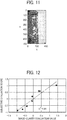
- FIG. 11 is a diagram illustrating color data correction according to the first embodiment.
- the evaluation-value calculator 169 calculates the evaluation value of the image clarity for each one of the samples 145.
- the evaluation-value calculator 169 calculates the evaluation value of the image clarity of each one of the samples 145 using Formula 2 given below.
- Formula 2 is a logarithmic equation in view of Weber-Fechner's law that "The relationship between stimulus and human sensitivity is logarithmic.”
- y denotes the image-clarity evaluation value
- x denotes the integrated value.
- q 1 0.80
- q 2 -2.86.
- Formula 2 as the color difference with black is smaller, ⁇ E black that is the denominator decreases in number and the image-clarity evaluation value y increases.
- FIG. 12 is a diagram illustrating the correlation between the image-clarity evaluation values and the subjective evaluation scores, according to the first embodiment.
- each of the samples 145 is indicated by a circle (dot).
- the contribution ratio R 2 is 0.90, which is very high, and it is recognizable that there is no inversion among the samples that have significant differences in evaluation value with the order in the subjective evaluation.
- the evaluation obtained by the formula for evaluation as in Formula 2 indicates a high correlation with the evaluation obtained by visual examination.
- the elements of the color data which is used by the reflective-property correction unit 168 to perform correction, include the levels of lightness and color saturation.
- the correlation between the color difference ⁇ E black and the lightness difference ⁇ L* black and the correlation between the color difference ⁇ E black and the color-saturation difference ⁇ C* black are observed, respectively.
- FIG. 13 is a diagram illustrating the correlation between the color difference and each of the lightness difference and the color-saturation difference. As illustrated in FIG. 13 , the contribution ratio R 2 of the lightness difference ⁇ L* black is 0.97, and the contribution ratio R 2 of the color-saturation difference ⁇ C* black is 0.01. This indicates that the contribution of the lightness difference is significantly high.
- FIG. 14 is a diagram illustrating the correlation between the image-clarity evaluation values and the subjective evaluation scores when correction is performed using lightness differences.
- the contribution ratio R 2 is 0.93. This indicates that the contribution ratio in FIG. 14 is higher than the contribution ratio in the scatter diagram of FIG. 12 . Accordingly, even when only lightness data is used for correction on the samples 145 that are used in the present embodiment, evaluation that is consistent with the visual check by human eyes can be achieved.
- FIG. 15 is a flowchart of image-clarity evaluation processes according to the first embodiment.
- the evaluation device 100 turns on the light source 110, and then starts projection (step S101). Accordingly, the light that is emitted from the light source 110 is collimated by the telecentric lens 120, and an image is formed on the diffusing board 130. Then, the virtual image 102 of the projection pattern 101 that is disposed on the diffusing board 130 is projected onto the sample 145 that is attached to the sample stage 140.
- the evaluation device 100 captures the virtual image 102 that is projected onto the sample 145 by the hyperspectral camera 150 to obtain two-dimensional image data (step S102). Moreover, in parallel with the capturing of the sample 145, the evaluation device 100 captures the reference whiteboard to obtain two-dimensional image data (step S103). Note that the processes in the step S103 may be performed in advance of the image-clarity evaluation, and the obtained two-dimensional image data may be stored in the storage device (for example, the RAM 64 or a HDD) of the evaluation unit 160.
- the storage device for example, the RAM 64 or a HDD
- the evaluation device 100 converts the two-dimensional image data that is captured and obtained by the hyperspectral camera 150 into L*a*b* image data (step S104). For example, the evaluation device 100 converts the spectral data obtained for the sample 145 and the spectral data obtained for the reference whiteboard into L*a*b* image data. Then, the evaluation device 100 binarizes the L* image data with a prescribed threshold based on the L*a*b* image data, and obtains the number for the amount of change in shape of the edge of the projection pattern 101 (step S105).
- the evaluation device 100 calculates and obtains an approximate straight line using the method of least squares for the shape-changing positions of the edges of the binarized image data (step S106). Subsequently, the evaluation device 100 calculates how much the shape of edge changes with reference to the approximate straight line, on a line-by-line basis (step S107). In other words, the evaluation device 100 calculates the amount of distortion. Then, the evaluation device 100 performs Fourier transform on the changes in edge to calculate and obtain the frequency characteristics of an edge-change portion (step S108). Then, the evaluation device 100 assigns a weight to the frequency characteristics of an edge-change portion using the visual transfer function (VTF) that is used to reflect the characteristics of human visual perception (step S109).
- VTF visual transfer function
- the evaluation device 100 integrates the weighted frequency characteristics (step S110). Then, the evaluation device 100 corrects an integrated value of the sample 145 using the color data of the sample 145 (step S111). For example, the evaluation device 100 calculates the average L*a*b* from the L*a*b* of each pixel of the light shielding member of the projection pattern 101, and divides the integrated value by the color difference ⁇ E black with black. Then, the evaluation device 100 calculates and obtains the evaluation value of the image clarity of the sample 145 using Formula 2 as above (step S112). As described above, lightness difference ⁇ L* black may be used to calculate and obtain the evaluation value in place of ⁇ E black .
- the evaluation device 100 corrects the amount of change in the shape of the virtual image of the projection pattern 101 reflected in the sample 145, using color data, and evaluates the image clarity of surface of the sample 145. Accordingly, the evaluation device 100 can evaluate the image clarity with a high degree of accuracy.
- the evaluation device 100 corrects the amount of change in the shape of the virtual image of the projection pattern 101 reflected in the sample 145, using the color data of the surface of the sample 145. Due to this configuration, the image-clarity evaluation that is more adjusted for the human chromatic sensitivity can be performed. Moreover, the evaluation device 100 evaluates the image clarity of surface of the sample 145 based on the subjective evaluation data that is obtained in advance. Due to this configuration, the evaluation value that highly correlates with the human perception can be calculated and obtained.
- the evaluation device 100 two-dimensionally measures the image clarity using the hyperspectral camera 150. Due to this configuration, the evaluation result in which the characteristics of the image clarity that is actually viewed and perceived by human are reflected can be derived. Moreover, the evaluation device 100 focuses on and captures an image of the virtual image 102. Due to this configuration, the image of the distortion on surface of the sample 145 can be captured with a high degree of precision.
- the hyperspectral camera 150 is used in the above first embodiment.
- the camera may be 3-channel red, green, and blue (RGB) camera.
- RGB red, green, and blue
- the second embodiment cases in which a RGB camera is used in place of the hyperspectral camera 150 are described by way of example.
- like reference signs are given to elements similar to those of the evaluation device 100 described in the first embodiment, and their detailed description may be omitted.
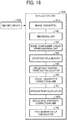
- FIG. 16 is a block diagram illustrating a functional configuration of the evaluation unit 160a according to the second embodiment.
- the RGB camera is depicted as an imaging device 150a.
- the evaluation device may be referred to as an evaluation device 100a as deemed appropriate.
- the evaluation unit 160a includes an image converter 161a, the binarizing unit 162, the edge-component linear approximation unit 163, the deviation calculator 164, and the frequency characteristics calculator 165. Moreover, the evaluation unit 160a includes the visual-character correction unit 166, the integration calculator 167, the reflective-property correction unit 168, and the evaluation-value calculator 169. Some of or all of these elements may be implemented by execution of software (program), or may also be implemented by hardware circuitry.
- the image converter 161a receives the image data that is captured and obtained by the imaging device 150a (i.e., the RGB camera), and converts the received image data into XYZ image data.
- the image converter 161a converts the image data into XYZ image data using Formula 3 given below.
- Formula 3 "i" and "j” denote the space coordinates.
- the formula that is used to convert RGB image data into XYZ image data is not limited to Formula 3.
- Formula 3 is a formula for performing conversion that is defined by the international telecommunication union (ITU). In general-purpose RGB cameras such as digital cameras, there are many cases in which y correction is performed on the measured RGB values.
- the original RGB values are obtained by performing correction before converting the image data into XYZ image data.
- ⁇ X i j 0.4305 ⁇ R i j + 0.3415 ⁇ G i j + 0.1784 ⁇ B i j
- Y i j 0.2220 ⁇ R i j + 0.7067 ⁇ G i j + 0.0713 ⁇ B i j
- Z i j 0.0202 ⁇ R i j + 0.1295 ⁇ G i j + 0.9394 ⁇ B i j
- FIG. 17 is a flowchart of image-clarity evaluation processes according to the second embodiment.
- the descriptions of the processes equivalent to those of the image-clarity evaluation processes according to the first embodiment are omitted.
- the processes in the step S201 to the step S203 are equivalent to the processes in the step S101 to the step S103.
- the processes in the step S205 to the step S213 are equivalent to the processes in the step S104 to the step S112.
- the evaluation device 100a receives the image data that is captured and obtained by the imaging device 150a (i.e., the RGB camera), and converts the received image data into XYZ image data (step S204). Then, the evaluation device 100a converts the obtained XYZ image data into L*a*b* image data (step S205).
- the imaging device 150a i.e., the RGB camera
- the evaluation device 100a converts the obtained XYZ image data into L*a*b* image data (step S205).
- the evaluation device 100a two-dimensionally measures the image clarity using an RGB camera. Accordingly, the image clarity can be evaluated with a more cost-effective configuration.
- the hyperspectral camera 150 is used in the above first embodiment.
- the contribution ratio is high in the correlation between the color difference ⁇ E black and the lightness difference ⁇ L* black (see FIG. 13 ).
- the contribution ratio is high in the correlation between the image-clarity evaluation values and the subjective evaluation scores when correction is performed using lightness differences (see FIG. 14 ). Due to this configuration, it is considered that a monochrome camera may also be used.
- cases in which a monochrome camera is used in place of the hyperspectral camera 150 are described by way of example.
- like reference signs are given to elements similar to those of the evaluation device 100 described in the first embodiment, and their detailed description may be omitted.
- FIG. 18 is a block diagram illustrating a functional configuration of the evaluation unit 160b according to the third embodiment.
- the monochrome camera is depicted as an imaging device 150b.
- the evaluation device may be referred to as an evaluation device 100b as deemed appropriate.
- the evaluation unit 160b includes an image converter 161b, the binarizing unit 162, the edge-component linear approximation unit 163, the deviation calculator 164, and the frequency characteristics calculator 165. Moreover, the evaluation unit 160b includes the visual-character correction unit 166, the integration calculator 167, a reflective-property correction unit 168b, and the evaluation-value calculator 169. Some of or all of these elements may be implemented by execution of software (program), or may also be implemented by hardware circuitry.
- the image converter 161b receives the image data that is captured and obtained by the imaging device 150b (i.e., the monochrome camera), and converts the received image data into reflectance image data. For example, the image converter 161b converts the image data into reflectance image data using Formula 4 given below.
- the reflectance image of the sample 145 is calculated and obtained using Formula 4, assuming that the reflectivity of the whiteboard is 100 percent. In Formula 4, "i" and "j" denote the space coordinates.
- Reflectance Image R Measured Reflectivity i j of Sample Measured Reflectivity i j of Whiteboard
- the reflective-property correction unit 168b corrects the integrated value of each one of the samples 145 using the reflectance data of each one of the samples 145. For example, the reflective-property correction unit 168b divides the integrated value, which is calculated and obtained by the integration calculator 167, by the difference in reflectance ⁇ R black between the reflectance "0" of black and the reflectance of the surface of the sample 145. As the surface of the sample 145 has a higher reflectance, the corrected integrated value becomes smaller. In the first embodiment, the contribution ratio of the lightness difference ⁇ L* black is high in the color difference ⁇ E black . By contrast, in the third embodiment, the reflectivity is measured using a monochrome camera in place of the hyperspectral camera 150 to evaluate the image clarity of the surface of the object.
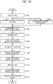
- FIG. 19 is a flowchart of image-clarity evaluation processes according to the third embodiment.
- the descriptions of the processes equivalent to those of the image-clarity evaluation processes according to the first embodiment are omitted.
- the processes in the step S301 to the step S303 are equivalent to the processes in the step S101 to the step S103.
- the processes in the step S305 to the step S310 are equivalent to the processes in the step S105 to the step S110.
- the processes in the step S312 are equivalent to the processes in the step S112.
- the evaluation device 100b receives the image data that is captured and obtained by the imaging device 150b (i.e., the monochrome camera), and converts the received image data into reflectance image data (step S304). Moreover, the evaluation device 100b corrects an integrated value of the sample 145 using the reflectance data of the sample 145 (step S311). For example, the evaluation device 100b divides the obtained integrated value by the difference in reflectance ⁇ R black between the reflectance "0" of black and the reflectance of the surface of the sample 145.
- the evaluation device 100b measures the reflectance using a monochrome camera, and evaluates the image clarity of surface of the sample 145. Accordingly, the image clarity can be evaluated with a more cost-effective configuration.
- an evaluation program that is executed by, for example, the evaluation unit 160 may be installed for distribution in any desired computer-readable recording medium such as a compact disc, a read-only memory (CD-ROM), a flexible disk (FD), a compact disc-recordable (CD-R), and a digital versatile disk (DVD) in a file format installable or executable by a computer.
- a computer-readable recording medium such as a compact disc, a read-only memory (CD-ROM), a flexible disk (FD), a compact disc-recordable (CD-R), and a digital versatile disk (DVD) in a file format installable or executable by a computer.
- such an evaluation program that is executed by, for example, the evaluation unit 160 may be stored on a computer that is connected to a network such as the Internet so as to be downloaded for distribution through the network.
- a network such as the Internet
- such an evaluation program that is executed by, for example, the evaluation unit 160 may be provided or distributed through a network such as the Internet.
- An evaluation program that is executed by the evaluation unit 160 has a module structure that includes at least the above-described elements (e.g., the reflective-property correction unit 168 and the evaluation-value calculator 169).
- a CPU reads and executes the evaluation program stored in a recording medium. Accordingly, the elements of the module structure mentioned as above are loaded into a main memory, and the reflective-property correction unit 168 and the evaluation-value calculator 169 are created in the main memory.
- any one of the above-described and other methods of the present invention may be embodied in the form of a computer program stored on any kind of storage medium.
- storage media include, but are not limited to, flexible disks, hard disks, optical discs, magneto-optical discs, magnetic tape, nonvolatile memory cards, ROM, etc.
- any one of the above-described and other methods of the present invention may be implemented by ASICs, prepared by interconnecting an appropriate network of conventional component circuits, or by a combination thereof with one or more conventional general-purpose microprocessors and/or signal processors programmed accordingly.
- the present invention can be implemented in any convenient form, for example using dedicated hardware, or a mixture of dedicated hardware and software.
- the present invention may be implemented as computer software implemented by one or more networked processing apparatuses.
- the network can comprise any conventional terrestrial or wireless communications network, such as the Internet.
- the processing apparatuses can compromise any suitably programmed apparatuses such as a general purpose computer, personal digital assistant, mobile telephone (such as a WAP or 3G-compliant phone) and so on. Since the present invention can be implemented as software, each and every aspect of the present invention thus encompasses computer software implementable on a programmable device.
- the computer software can be provided to the programmable device using any conventional carrier medium.
- the carrier medium can compromise a transient carrier medium such as an electrical, optical, microwave, acoustic or radio frequency signal carrying the computer code.
- a transient carrier medium such as an electrical, optical, microwave, acoustic or radio frequency signal carrying the computer code.
- An example of such a transient medium is a TCP/IP signal carrying computer code over an IP network, such as the Internet.
- the carrier medium can also comprise a storage medium for storing processor readable code such as a floppy disk, hard disk, CD ROM, magnetic tape device or solid state memory device.
- the hardware platform includes any desired kind of hardware resources including, for example, a CPU, a RAM, and a HDD.
- the CPU may be implemented by any desired kind of any desired number of processor.
- the RAM may be implemented by any desired kind of volatile or non-volatile memory.
- the HDD may be implemented by any desired kind of non-volatile memory capable of storing a large amount of data.
- the hardware resources may additionally include an input device, an output device, or a network device, depending on the type of the apparatus. Alternatively, the HDD may be provided outside of the apparatus as long as the HDD is accessible.
- the CPU such as a cache memory of the CPU
- the RAM may function as a physical memory or a primary memory of the apparatus, while the HDD may function as a secondary memory of the apparatus.
Landscapes
- Engineering & Computer Science (AREA)
- Physics & Mathematics (AREA)
- General Physics & Mathematics (AREA)
- Computer Vision & Pattern Recognition (AREA)
- Theoretical Computer Science (AREA)
- Chemical & Material Sciences (AREA)
- Health & Medical Sciences (AREA)
- Life Sciences & Earth Sciences (AREA)
- Mathematical Physics (AREA)
- Analytical Chemistry (AREA)
- Biochemistry (AREA)
- General Health & Medical Sciences (AREA)
- Immunology (AREA)
- Pathology (AREA)
- Quality & Reliability (AREA)
- Spectrometry And Color Measurement (AREA)
- Investigating Or Analysing Materials By Optical Means (AREA)
- Image Analysis (AREA)
Applications Claiming Priority (1)
| Application Number | Priority Date | Filing Date | Title |
|---|---|---|---|
| JP2017108484A JP6969164B2 (ja) | 2017-05-31 | 2017-05-31 | 評価装置、評価プログラム及び評価方法 |
Publications (3)
| Publication Number | Publication Date |
|---|---|
| EP3410101A1 true EP3410101A1 (de) | 2018-12-05 |
| EP3410101B1 EP3410101B1 (de) | 2022-08-24 |
| EP3410101B8 EP3410101B8 (de) | 2022-09-28 |
Family
ID=62244340
Family Applications (1)
| Application Number | Title | Priority Date | Filing Date |
|---|---|---|---|
| EP18173895.6A Active EP3410101B8 (de) | 2017-05-31 | 2018-05-23 | Auswertungsvorrichtung und aufzeichnungsmedium zur speicherung eines auswertungsprogramms |
Country Status (3)
| Country | Link |
|---|---|
| US (1) | US10614563B2 (de) |
| EP (1) | EP3410101B8 (de) |
| JP (1) | JP6969164B2 (de) |
Families Citing this family (7)
| Publication number | Priority date | Publication date | Assignee | Title |
|---|---|---|---|---|
| JP7326972B2 (ja) * | 2019-07-30 | 2023-08-16 | 株式会社リコー | 表面特性評価方法、表面特性評価装置、及び表面特性評価プログラム |
| JP7289278B2 (ja) * | 2020-04-02 | 2023-06-09 | 東芝三菱電機産業システム株式会社 | 色むら監視装置 |
| JP7585715B2 (ja) | 2020-10-28 | 2024-11-19 | 株式会社リコー | カラーチャート、情報処理装置および情報処理システム |
| JP7661687B2 (ja) | 2020-10-29 | 2025-04-15 | 株式会社リコー | カラーチャート、情報処理装置および情報処理システム |
| US12125195B2 (en) | 2022-03-04 | 2024-10-22 | Ricoh Company, Ltd. | Inspection system, inspection method, and non-transitory recording medium |
| US12301770B2 (en) | 2022-03-08 | 2025-05-13 | Ricoh Company, Ltd. | Information processing apparatus, abnormality detection method, storage medium, and information processing system |
| CN116309491A (zh) * | 2023-03-24 | 2023-06-23 | 赛纳生物科技(广州)有限公司 | 一种评估荧光图像清晰度和点圆度的方法 |
Citations (3)
| Publication number | Priority date | Publication date | Assignee | Title |
|---|---|---|---|---|
| US5155558A (en) * | 1990-09-19 | 1992-10-13 | E. I. Du Pont De Nemours And Company | Method and apparatus for analyzing the appearance features of a surface |
| JP2007155709A (ja) | 2005-11-11 | 2007-06-21 | Arc Harima Kk | 写像性の評価方法 |
| US20160040985A1 (en) * | 2014-08-05 | 2016-02-11 | Sho NAGAI | Specimen measuring device and computer program product |
Family Cites Families (48)
| Publication number | Priority date | Publication date | Assignee | Title |
|---|---|---|---|---|
| JPS5897608A (ja) * | 1981-12-05 | 1983-06-10 | Nippon Paint Co Ltd | 表面性状測定方法および装置 |
| JPH07104921B2 (ja) * | 1989-11-17 | 1995-11-13 | 松下電器産業株式会社 | 画像閾値決定方法 |
| JP2588297B2 (ja) * | 1990-06-20 | 1997-03-05 | 日産自動車株式会社 | 塗装表面の鮮映性評価方法 |
| US5241188A (en) * | 1991-02-01 | 1993-08-31 | Nikon Corporation | Apparatus for detecting a focussing position |
| US5617484A (en) * | 1992-09-25 | 1997-04-01 | Olympus Optical Co., Ltd. | Image binarizing apparatus |
| JPH08166615A (ja) * | 1994-12-14 | 1996-06-25 | Nikon Corp | 振れ補正機能を備えたカメラ |
| JPH10132532A (ja) * | 1996-10-28 | 1998-05-22 | Omron Corp | パターン検査システムおよび方法 |
| JPH1139486A (ja) * | 1997-07-24 | 1999-02-12 | Ricoh Co Ltd | 画像の画質評価方法 |
| US6248486B1 (en) * | 1998-11-23 | 2001-06-19 | U.S. Philips Corporation | Method of detecting aberrations of an optical imaging system |
| US6368763B2 (en) * | 1998-11-23 | 2002-04-09 | U.S. Philips Corporation | Method of detecting aberrations of an optical imaging system |
| DE19930688A1 (de) * | 1999-07-02 | 2001-01-04 | Byk Gardner Gmbh | Vorrichtung und Verfahren zur Bestimmung der Qualität von Oberflächen |
| JP2001235319A (ja) * | 2000-02-22 | 2001-08-31 | Sumitomo Chem Co Ltd | シェーディング補正装置及びシェーディング補正方法及び表面検査装置 |
| WO2001080172A1 (fr) * | 2000-04-19 | 2001-10-25 | Kabushiki Kaisha Topcon | Appareil et systeme d'evaluation de l'authenticite d'une carte |
| JP3559754B2 (ja) * | 2000-07-25 | 2004-09-02 | Necエレクトロニクス株式会社 | 指紋認証装置 |
| JP3930334B2 (ja) * | 2001-03-21 | 2007-06-13 | 株式会社資生堂 | 分光反射率測定装置 |
| US6509964B2 (en) * | 2001-05-15 | 2003-01-21 | Amt Inc. | Multi-beam apparatus for measuring surface quality |
| JP3884321B2 (ja) * | 2001-06-26 | 2007-02-21 | オリンパス株式会社 | 3次元情報取得装置、3次元情報取得における投影パターン、及び、3次元情報取得方法 |
| DE10163351C1 (de) * | 2001-12-14 | 2003-06-26 | Heimann Biometric Systems Gmbh | Verfahren und Anordnung zur verzerrungsarmen Aufnahme von an einer Kontaktfläche durch gestörte Totalreflexion entstehenden Intensitätsmustern |
| JP4053414B2 (ja) * | 2002-12-11 | 2008-02-27 | シーケーディ株式会社 | 三次元計測装置 |
| JP2004212385A (ja) * | 2002-12-19 | 2004-07-29 | Olympus Corp | 撮影装置とその撮影装置の撮影方法及び制御方法 |
| JP4098269B2 (ja) * | 2004-03-31 | 2008-06-11 | ライオンエンジニアリング株式会社 | Ptpシートの検査装置及び検査方法 |
| WO2005101312A2 (en) * | 2004-04-13 | 2005-10-27 | Aic | Fractal skr-method for evaluating image quality |
| CN100533661C (zh) * | 2004-07-12 | 2009-08-26 | 株式会社尼康 | 曝光条件的决定方法、曝光方法及装置、组件制造方法 |
| EP1909062B1 (de) * | 2005-07-08 | 2014-03-05 | Nikon Corporation | Oberflächenpositions-detektionsvorrichtung, belichtungsvorrichtung und belichtungsverfahren |
| WO2007058188A1 (ja) * | 2005-11-15 | 2007-05-24 | Nikon Corporation | 露光装置及び露光方法、並びにデバイス製造方法 |
| DE102005062618B4 (de) * | 2005-12-23 | 2008-05-08 | Carl Zeiss Smt Ag | Optische Abbildungseinrichtung und Abbildungsverfahren mit Bestimmung von Abbildungsfehlern |
| KR100714280B1 (ko) * | 2006-04-27 | 2007-05-02 | 삼성전자주식회사 | 오버레이 계측설비 및 그를 이용한 오버레이 계측방법 |
| JP5092738B2 (ja) * | 2007-12-26 | 2012-12-05 | ソニー株式会社 | 画像処理装置及び方法、並びにプログラム |
| US8238641B2 (en) * | 2008-06-20 | 2012-08-07 | Arc Harima Co., Ltd. | Method for measuring mirror index and apparatus thereof |
| JP5257170B2 (ja) * | 2009-03-13 | 2013-08-07 | 株式会社リコー | 光沢ムラ評価装置、光沢ムラ評価方法、画像形成装置及び記録媒体 |
| US8585956B1 (en) * | 2009-10-23 | 2013-11-19 | Therma-Tru, Inc. | Systems and methods for laser marking work pieces |
| JP5681021B2 (ja) * | 2011-04-01 | 2015-03-04 | アークハリマ株式会社 | 表面性状測定装置 |
| JP5838081B2 (ja) * | 2011-11-25 | 2015-12-24 | 株式会社オプトコム | 光特性ムラ測定装置及び光特性ムラ測定方法 |
| US9541375B2 (en) * | 2012-07-20 | 2017-01-10 | Samsung Electronics Co., Ltd. | Method and apparatus for generating tomography images |
| US8823930B2 (en) * | 2012-08-07 | 2014-09-02 | Carl Zeiss Industrielle Messtechnik Gmbh | Apparatus and method for inspecting an object |
| JP6069628B2 (ja) * | 2012-12-03 | 2017-02-01 | 北陽電機株式会社 | 偏向装置、光走査装置及び走査式測距装置 |
| JP6080259B2 (ja) * | 2013-02-06 | 2017-02-15 | 日本電産サンキョー株式会社 | 文字切り出し装置及び文字切り出し方法 |
| US9594245B2 (en) * | 2013-06-06 | 2017-03-14 | Hamamatsu Photonics K.K. | Adjustment method for adaptive optics system, adaptive optics system, and storage medium storing program for adaptive optics system |
| JP2015094602A (ja) * | 2013-11-08 | 2015-05-18 | 大日本印刷株式会社 | 印画物の光沢感の評価方法および印画物の製造方法 |
| JP6324113B2 (ja) * | 2014-02-28 | 2018-05-16 | キヤノン株式会社 | 光学系および光沢計 |
| DE102014104029B3 (de) * | 2014-03-24 | 2015-04-23 | Sick Ag | Optoelektronische Vorrichtung und Verfahren zur Aufnahme von scharfen Bildern |
| TWI557462B (zh) * | 2014-11-28 | 2016-11-11 | 台灣愛美科股份有限公司 | 自動聚焦系統與方法 |
| EP3193158B1 (de) * | 2016-01-14 | 2020-06-17 | Volkswagen AG | System und verfahren zur beurteilung des visuellen erscheinungsbildes einer reflektierenden oberfläche |
| US9779492B1 (en) * | 2016-03-15 | 2017-10-03 | International Business Machines Corporation | Retinal image quality assessment, error identification and automatic quality correction |
| JP2017173300A (ja) * | 2016-03-16 | 2017-09-28 | 株式会社リコー | 質感評価装置、質感評価方法、及びプログラム |
| EP3220101B1 (de) | 2016-03-16 | 2020-01-29 | Ricoh Company, Ltd. | Texturbeurteilungsvorrichtung, texturbeurteilungsverfahren und computerlesbares aufzeichnungsmedium |
| US10165194B1 (en) * | 2016-12-16 | 2018-12-25 | Amazon Technologies, Inc. | Multi-sensor camera system |
| US10146041B1 (en) * | 2018-05-01 | 2018-12-04 | Nanotronics Imaging, Inc. | Systems, devices and methods for automatic microscope focus |
-
2017
- 2017-05-31 JP JP2017108484A patent/JP6969164B2/ja active Active
-
2018
- 2018-05-23 EP EP18173895.6A patent/EP3410101B8/de active Active
- 2018-05-31 US US15/994,168 patent/US10614563B2/en active Active
Patent Citations (3)
| Publication number | Priority date | Publication date | Assignee | Title |
|---|---|---|---|---|
| US5155558A (en) * | 1990-09-19 | 1992-10-13 | E. I. Du Pont De Nemours And Company | Method and apparatus for analyzing the appearance features of a surface |
| JP2007155709A (ja) | 2005-11-11 | 2007-06-21 | Arc Harima Kk | 写像性の評価方法 |
| US20160040985A1 (en) * | 2014-08-05 | 2016-02-11 | Sho NAGAI | Specimen measuring device and computer program product |
Also Published As
| Publication number | Publication date |
|---|---|
| JP6969164B2 (ja) | 2021-11-24 |
| US10614563B2 (en) | 2020-04-07 |
| US20180350059A1 (en) | 2018-12-06 |
| EP3410101B1 (de) | 2022-08-24 |
| JP2018205037A (ja) | 2018-12-27 |
| EP3410101B8 (de) | 2022-09-28 |
Similar Documents
| Publication | Publication Date | Title |
|---|---|---|
| EP3410101B1 (de) | Auswertungsvorrichtung und aufzeichnungsmedium zur speicherung eines auswertungsprogramms | |
| US10593031B2 (en) | Texture evaluation apparatus, texture evaluation method, and computer-readable recording medium | |
| US7679747B2 (en) | Gloss measurement apparatus and gloss measurement method | |
| US10161796B1 (en) | LED lighting based multispectral imaging system for color measurement | |
| US8619153B2 (en) | Radiometric calibration using temporal irradiance mixtures | |
| JP2017173300A (ja) | 質感評価装置、質感評価方法、及びプログラム | |
| JP2020012668A (ja) | 評価装置、計測装置、評価方法および評価プログラム | |
| WO2021059858A1 (ja) | 検査方法、プログラム、及び、検査システム | |
| US12121133B2 (en) | Method for determining a greyness level of a strand of hair | |
| JP2023134554A (ja) | 顔認証環境判定方法、顔認証環境判定システム、顔認証環境判定装置、顔認証環境判定プログラム、肌色チャート、及び肌色チャートの製造方法 | |
| CN109632087A (zh) | 适用于成像亮度计的现场标定方法及成像亮度计标定装置 | |
| CN103200349A (zh) | 一种扫描图像色偏自动检测方法 | |
| Tominaga et al. | Estimation of surface properties for art paintings using a six-band scanner | |
| US12125220B2 (en) | Surface characteristics evaluation method, surface characteristics evaluation apparatus, and surface characteristics evaluation program | |
| JP7308443B2 (ja) | 評価装置、本物感評価方法およびプログラム | |
| JPWO1998027744A1 (ja) | 撮影システム | |
| JP2002350355A (ja) | 光沢ムラ評価装置、光沢ムラ評価方法及び該方法を実行するためのプログラムを格納したコンピュータ読み取り可能な記憶媒体 | |
| JP5120936B2 (ja) | 画像処理装置および画像処理方法 | |
| JP2020094936A (ja) | 塗装面評価方法、塗装面評価装置、及びプログラム | |
| KR20200090296A (ko) | 구조적 깊이 카메라 시스템에서 인코딩 장치 및 방법 | |
| Sone et al. | Measurement and evaluation method of orange peel | |
| RU2288453C2 (ru) | Способ измерения цвета поверхности и измеритель цвета поверхности | |
| JP2009182845A (ja) | 画像処理装置および画像処理方法 | |
| WO2025115710A1 (ja) | 画像の補正に用いられる方法、およびその方法を実行する処理回路 | |
| JP2022062908A (ja) | 画像処理装置、画像処理方法およびプログラム |
Legal Events
| Date | Code | Title | Description |
|---|---|---|---|
| PUAI | Public reference made under article 153(3) epc to a published international application that has entered the european phase |
Free format text: ORIGINAL CODE: 0009012 |
|
| STAA | Information on the status of an ep patent application or granted ep patent |
Free format text: STATUS: REQUEST FOR EXAMINATION WAS MADE |
|
| 17P | Request for examination filed |
Effective date: 20180523 |
|
| AK | Designated contracting states |
Kind code of ref document: A1 Designated state(s): AL AT BE BG CH CY CZ DE DK EE ES FI FR GB GR HR HU IE IS IT LI LT LU LV MC MK MT NL NO PL PT RO RS SE SI SK SM TR |
|
| AX | Request for extension of the european patent |
Extension state: BA ME |
|
| STAA | Information on the status of an ep patent application or granted ep patent |
Free format text: STATUS: EXAMINATION IS IN PROGRESS |
|
| 17Q | First examination report despatched |
Effective date: 20210610 |
|
| REG | Reference to a national code |
Ref country code: DE Ref legal event code: R079 Ref document number: 602018039604 Country of ref document: DE Free format text: PREVIOUS MAIN CLASS: G01N0021840000 Ipc: G01J0003460000 |
|
| RIC1 | Information provided on ipc code assigned before grant |
Ipc: G01N 21/88 20060101ALI20220505BHEP Ipc: G01N 21/84 20060101ALI20220505BHEP Ipc: G01N 21/55 20140101ALI20220505BHEP Ipc: G01N 21/31 20060101ALI20220505BHEP Ipc: G01J 3/46 20060101AFI20220505BHEP |
|
| GRAP | Despatch of communication of intention to grant a patent |
Free format text: ORIGINAL CODE: EPIDOSNIGR1 |
|
| STAA | Information on the status of an ep patent application or granted ep patent |
Free format text: STATUS: GRANT OF PATENT IS INTENDED |
|
| INTG | Intention to grant announced |
Effective date: 20220617 |
|
| GRAS | Grant fee paid |
Free format text: ORIGINAL CODE: EPIDOSNIGR3 |
|
| GRAA | (expected) grant |
Free format text: ORIGINAL CODE: 0009210 |
|
| STAA | Information on the status of an ep patent application or granted ep patent |
Free format text: STATUS: THE PATENT HAS BEEN GRANTED |
|
| GRAT | Correction requested after decision to grant or after decision to maintain patent in amended form |
Free format text: ORIGINAL CODE: EPIDOSNCDEC |
|
| AK | Designated contracting states |
Kind code of ref document: B1 Designated state(s): AL AT BE BG CH CY CZ DE DK EE ES FI FR GB GR HR HU IE IS IT LI LT LU LV MC MK MT NL NO PL PT RO RS SE SI SK SM TR |
|
| REG | Reference to a national code |
Ref country code: CH Ref legal event code: PK Free format text: BERICHTIGUNG B8 Ref country code: CH Ref legal event code: EP |
|
| REG | Reference to a national code |
Ref country code: DE Ref legal event code: R096 Ref document number: 602018039604 Country of ref document: DE |
|
| RAP4 | Party data changed (patent owner data changed or rights of a patent transferred) |
Owner name: RICOH COMPANY, LTD. |
|
| REG | Reference to a national code |
Ref country code: IE Ref legal event code: FG4D |
|
| REG | Reference to a national code |
Ref country code: AT Ref legal event code: REF Ref document number: 1513961 Country of ref document: AT Kind code of ref document: T Effective date: 20220915 |
|
| REG | Reference to a national code |
Ref country code: LT Ref legal event code: MG9D |
|
| REG | Reference to a national code |
Ref country code: NL Ref legal event code: MP Effective date: 20220824 |
|
| PG25 | Lapsed in a contracting state [announced via postgrant information from national office to epo] |
Ref country code: SE Free format text: LAPSE BECAUSE OF FAILURE TO SUBMIT A TRANSLATION OF THE DESCRIPTION OR TO PAY THE FEE WITHIN THE PRESCRIBED TIME-LIMIT Effective date: 20220824 Ref country code: RS Free format text: LAPSE BECAUSE OF FAILURE TO SUBMIT A TRANSLATION OF THE DESCRIPTION OR TO PAY THE FEE WITHIN THE PRESCRIBED TIME-LIMIT Effective date: 20220824 Ref country code: PT Free format text: LAPSE BECAUSE OF FAILURE TO SUBMIT A TRANSLATION OF THE DESCRIPTION OR TO PAY THE FEE WITHIN THE PRESCRIBED TIME-LIMIT Effective date: 20221226 Ref country code: NO Free format text: LAPSE BECAUSE OF FAILURE TO SUBMIT A TRANSLATION OF THE DESCRIPTION OR TO PAY THE FEE WITHIN THE PRESCRIBED TIME-LIMIT Effective date: 20221124 Ref country code: NL Free format text: LAPSE BECAUSE OF FAILURE TO SUBMIT A TRANSLATION OF THE DESCRIPTION OR TO PAY THE FEE WITHIN THE PRESCRIBED TIME-LIMIT Effective date: 20220824 Ref country code: LV Free format text: LAPSE BECAUSE OF FAILURE TO SUBMIT A TRANSLATION OF THE DESCRIPTION OR TO PAY THE FEE WITHIN THE PRESCRIBED TIME-LIMIT Effective date: 20220824 Ref country code: LT Free format text: LAPSE BECAUSE OF FAILURE TO SUBMIT A TRANSLATION OF THE DESCRIPTION OR TO PAY THE FEE WITHIN THE PRESCRIBED TIME-LIMIT Effective date: 20220824 Ref country code: FI Free format text: LAPSE BECAUSE OF FAILURE TO SUBMIT A TRANSLATION OF THE DESCRIPTION OR TO PAY THE FEE WITHIN THE PRESCRIBED TIME-LIMIT Effective date: 20220824 |
|
| REG | Reference to a national code |
Ref country code: AT Ref legal event code: MK05 Ref document number: 1513961 Country of ref document: AT Kind code of ref document: T Effective date: 20220824 |
|
| PG25 | Lapsed in a contracting state [announced via postgrant information from national office to epo] |
Ref country code: PL Free format text: LAPSE BECAUSE OF FAILURE TO SUBMIT A TRANSLATION OF THE DESCRIPTION OR TO PAY THE FEE WITHIN THE PRESCRIBED TIME-LIMIT Effective date: 20220824 Ref country code: IS Free format text: LAPSE BECAUSE OF FAILURE TO SUBMIT A TRANSLATION OF THE DESCRIPTION OR TO PAY THE FEE WITHIN THE PRESCRIBED TIME-LIMIT Effective date: 20221224 Ref country code: HR Free format text: LAPSE BECAUSE OF FAILURE TO SUBMIT A TRANSLATION OF THE DESCRIPTION OR TO PAY THE FEE WITHIN THE PRESCRIBED TIME-LIMIT Effective date: 20220824 Ref country code: GR Free format text: LAPSE BECAUSE OF FAILURE TO SUBMIT A TRANSLATION OF THE DESCRIPTION OR TO PAY THE FEE WITHIN THE PRESCRIBED TIME-LIMIT Effective date: 20221125 |
|
| PG25 | Lapsed in a contracting state [announced via postgrant information from national office to epo] |
Ref country code: SM Free format text: LAPSE BECAUSE OF FAILURE TO SUBMIT A TRANSLATION OF THE DESCRIPTION OR TO PAY THE FEE WITHIN THE PRESCRIBED TIME-LIMIT Effective date: 20220824 Ref country code: RO Free format text: LAPSE BECAUSE OF FAILURE TO SUBMIT A TRANSLATION OF THE DESCRIPTION OR TO PAY THE FEE WITHIN THE PRESCRIBED TIME-LIMIT Effective date: 20220824 Ref country code: ES Free format text: LAPSE BECAUSE OF FAILURE TO SUBMIT A TRANSLATION OF THE DESCRIPTION OR TO PAY THE FEE WITHIN THE PRESCRIBED TIME-LIMIT Effective date: 20220824 Ref country code: DK Free format text: LAPSE BECAUSE OF FAILURE TO SUBMIT A TRANSLATION OF THE DESCRIPTION OR TO PAY THE FEE WITHIN THE PRESCRIBED TIME-LIMIT Effective date: 20220824 Ref country code: CZ Free format text: LAPSE BECAUSE OF FAILURE TO SUBMIT A TRANSLATION OF THE DESCRIPTION OR TO PAY THE FEE WITHIN THE PRESCRIBED TIME-LIMIT Effective date: 20220824 Ref country code: AT Free format text: LAPSE BECAUSE OF FAILURE TO SUBMIT A TRANSLATION OF THE DESCRIPTION OR TO PAY THE FEE WITHIN THE PRESCRIBED TIME-LIMIT Effective date: 20220824 |
|
| REG | Reference to a national code |
Ref country code: DE Ref legal event code: R097 Ref document number: 602018039604 Country of ref document: DE |
|
| PG25 | Lapsed in a contracting state [announced via postgrant information from national office to epo] |
Ref country code: SK Free format text: LAPSE BECAUSE OF FAILURE TO SUBMIT A TRANSLATION OF THE DESCRIPTION OR TO PAY THE FEE WITHIN THE PRESCRIBED TIME-LIMIT Effective date: 20220824 Ref country code: EE Free format text: LAPSE BECAUSE OF FAILURE TO SUBMIT A TRANSLATION OF THE DESCRIPTION OR TO PAY THE FEE WITHIN THE PRESCRIBED TIME-LIMIT Effective date: 20220824 |
|
| P01 | Opt-out of the competence of the unified patent court (upc) registered |
Effective date: 20230522 |
|
| PG25 | Lapsed in a contracting state [announced via postgrant information from national office to epo] |
Ref country code: AL Free format text: LAPSE BECAUSE OF FAILURE TO SUBMIT A TRANSLATION OF THE DESCRIPTION OR TO PAY THE FEE WITHIN THE PRESCRIBED TIME-LIMIT Effective date: 20220824 |
|
| PLBE | No opposition filed within time limit |
Free format text: ORIGINAL CODE: 0009261 |
|
| STAA | Information on the status of an ep patent application or granted ep patent |
Free format text: STATUS: NO OPPOSITION FILED WITHIN TIME LIMIT |
|
| 26N | No opposition filed |
Effective date: 20230525 |
|
| PG25 | Lapsed in a contracting state [announced via postgrant information from national office to epo] |
Ref country code: SI Free format text: LAPSE BECAUSE OF FAILURE TO SUBMIT A TRANSLATION OF THE DESCRIPTION OR TO PAY THE FEE WITHIN THE PRESCRIBED TIME-LIMIT Effective date: 20220824 |
|
| REG | Reference to a national code |
Ref country code: CH Ref legal event code: PL |
|
| PG25 | Lapsed in a contracting state [announced via postgrant information from national office to epo] |
Ref country code: MC Free format text: LAPSE BECAUSE OF FAILURE TO SUBMIT A TRANSLATION OF THE DESCRIPTION OR TO PAY THE FEE WITHIN THE PRESCRIBED TIME-LIMIT Effective date: 20220824 |
|
| REG | Reference to a national code |
Ref country code: BE Ref legal event code: MM Effective date: 20230531 |
|
| PG25 | Lapsed in a contracting state [announced via postgrant information from national office to epo] |
Ref country code: MC Free format text: LAPSE BECAUSE OF FAILURE TO SUBMIT A TRANSLATION OF THE DESCRIPTION OR TO PAY THE FEE WITHIN THE PRESCRIBED TIME-LIMIT Effective date: 20220824 Ref country code: LU Free format text: LAPSE BECAUSE OF NON-PAYMENT OF DUE FEES Effective date: 20230523 Ref country code: LI Free format text: LAPSE BECAUSE OF NON-PAYMENT OF DUE FEES Effective date: 20230531 Ref country code: CH Free format text: LAPSE BECAUSE OF NON-PAYMENT OF DUE FEES Effective date: 20230531 |
|
| REG | Reference to a national code |
Ref country code: IE Ref legal event code: MM4A |
|
| PG25 | Lapsed in a contracting state [announced via postgrant information from national office to epo] |
Ref country code: IE Free format text: LAPSE BECAUSE OF NON-PAYMENT OF DUE FEES Effective date: 20230523 |
|
| PG25 | Lapsed in a contracting state [announced via postgrant information from national office to epo] |
Ref country code: IE Free format text: LAPSE BECAUSE OF NON-PAYMENT OF DUE FEES Effective date: 20230523 |
|
| PG25 | Lapsed in a contracting state [announced via postgrant information from national office to epo] |
Ref country code: IT Free format text: LAPSE BECAUSE OF FAILURE TO SUBMIT A TRANSLATION OF THE DESCRIPTION OR TO PAY THE FEE WITHIN THE PRESCRIBED TIME-LIMIT Effective date: 20220824 Ref country code: BE Free format text: LAPSE BECAUSE OF NON-PAYMENT OF DUE FEES Effective date: 20230531 |
|
| PG25 | Lapsed in a contracting state [announced via postgrant information from national office to epo] |
Ref country code: BG Free format text: LAPSE BECAUSE OF FAILURE TO SUBMIT A TRANSLATION OF THE DESCRIPTION OR TO PAY THE FEE WITHIN THE PRESCRIBED TIME-LIMIT Effective date: 20220824 |
|
| PG25 | Lapsed in a contracting state [announced via postgrant information from national office to epo] |
Ref country code: BG Free format text: LAPSE BECAUSE OF FAILURE TO SUBMIT A TRANSLATION OF THE DESCRIPTION OR TO PAY THE FEE WITHIN THE PRESCRIBED TIME-LIMIT Effective date: 20220824 |
|
| PGFP | Annual fee paid to national office [announced via postgrant information from national office to epo] |
Ref country code: DE Payment date: 20250521 Year of fee payment: 8 |
|
| PGFP | Annual fee paid to national office [announced via postgrant information from national office to epo] |
Ref country code: GB Payment date: 20250527 Year of fee payment: 8 |
|
| PGFP | Annual fee paid to national office [announced via postgrant information from national office to epo] |
Ref country code: FR Payment date: 20250528 Year of fee payment: 8 |
|
| PG25 | Lapsed in a contracting state [announced via postgrant information from national office to epo] |
Ref country code: CY Free format text: LAPSE BECAUSE OF FAILURE TO SUBMIT A TRANSLATION OF THE DESCRIPTION OR TO PAY THE FEE WITHIN THE PRESCRIBED TIME-LIMIT; INVALID AB INITIO Effective date: 20180523 |
|
| PG25 | Lapsed in a contracting state [announced via postgrant information from national office to epo] |
Ref country code: HU Free format text: LAPSE BECAUSE OF FAILURE TO SUBMIT A TRANSLATION OF THE DESCRIPTION OR TO PAY THE FEE WITHIN THE PRESCRIBED TIME-LIMIT; INVALID AB INITIO Effective date: 20180523 |
|
| PG25 | Lapsed in a contracting state [announced via postgrant information from national office to epo] |
Ref country code: TR Free format text: LAPSE BECAUSE OF FAILURE TO SUBMIT A TRANSLATION OF THE DESCRIPTION OR TO PAY THE FEE WITHIN THE PRESCRIBED TIME-LIMIT Effective date: 20220824 |