EP3409943B1 - Plungerpumpe sowie verwendung einer plungerpumpe - Google Patents
Plungerpumpe sowie verwendung einer plungerpumpe Download PDFInfo
- Publication number
- EP3409943B1 EP3409943B1 EP18173921.0A EP18173921A EP3409943B1 EP 3409943 B1 EP3409943 B1 EP 3409943B1 EP 18173921 A EP18173921 A EP 18173921A EP 3409943 B1 EP3409943 B1 EP 3409943B1
- Authority
- EP
- European Patent Office
- Prior art keywords
- chamber
- plunger
- plunger pump
- pump according
- pressure
- Prior art date
- Legal status (The legal status is an assumption and is not a legal conclusion. Google has not performed a legal analysis and makes no representation as to the accuracy of the status listed.)
- Active
Links
Images
Classifications
-
- F—MECHANICAL ENGINEERING; LIGHTING; HEATING; WEAPONS; BLASTING
- F04—POSITIVE - DISPLACEMENT MACHINES FOR LIQUIDS; PUMPS FOR LIQUIDS OR ELASTIC FLUIDS
- F04B—POSITIVE-DISPLACEMENT MACHINES FOR LIQUIDS; PUMPS
- F04B1/00—Multi-cylinder machines or pumps characterised by number or arrangement of cylinders
- F04B1/04—Multi-cylinder machines or pumps characterised by number or arrangement of cylinders having cylinders in star- or fan-arrangement
- F04B1/0404—Details or component parts
- F04B1/0408—Pistons
-
- A—HUMAN NECESSITIES
- A01—AGRICULTURE; FORESTRY; ANIMAL HUSBANDRY; HUNTING; TRAPPING; FISHING
- A01J—MANUFACTURE OF DAIRY PRODUCTS
- A01J11/00—Apparatus for treating milk
- A01J11/16—Homogenising milk
-
- F—MECHANICAL ENGINEERING; LIGHTING; HEATING; WEAPONS; BLASTING
- F04—POSITIVE - DISPLACEMENT MACHINES FOR LIQUIDS; PUMPS FOR LIQUIDS OR ELASTIC FLUIDS
- F04B—POSITIVE-DISPLACEMENT MACHINES FOR LIQUIDS; PUMPS
- F04B1/00—Multi-cylinder machines or pumps characterised by number or arrangement of cylinders
- F04B1/04—Multi-cylinder machines or pumps characterised by number or arrangement of cylinders having cylinders in star- or fan-arrangement
- F04B1/0404—Details or component parts
- F04B1/0448—Sealing means, e.g. for shafts or housings
-
- F—MECHANICAL ENGINEERING; LIGHTING; HEATING; WEAPONS; BLASTING
- F04—POSITIVE - DISPLACEMENT MACHINES FOR LIQUIDS; PUMPS FOR LIQUIDS OR ELASTIC FLUIDS
- F04B—POSITIVE-DISPLACEMENT MACHINES FOR LIQUIDS; PUMPS
- F04B15/00—Pumps adapted to handle specific fluids, e.g. by selection of specific materials for pumps or pump parts
-
- F—MECHANICAL ENGINEERING; LIGHTING; HEATING; WEAPONS; BLASTING
- F04—POSITIVE - DISPLACEMENT MACHINES FOR LIQUIDS; PUMPS FOR LIQUIDS OR ELASTIC FLUIDS
- F04B—POSITIVE-DISPLACEMENT MACHINES FOR LIQUIDS; PUMPS
- F04B53/00—Component parts, details or accessories not provided for in, or of interest apart from, groups F04B1/00 - F04B23/00 or F04B39/00 - F04B47/00
- F04B53/14—Pistons, piston-rods or piston-rod connections
- F04B53/143—Sealing provided on the piston
-
- F—MECHANICAL ENGINEERING; LIGHTING; HEATING; WEAPONS; BLASTING
- F16—ENGINEERING ELEMENTS AND UNITS; GENERAL MEASURES FOR PRODUCING AND MAINTAINING EFFECTIVE FUNCTIONING OF MACHINES OR INSTALLATIONS; THERMAL INSULATION IN GENERAL
- F16J—PISTONS; CYLINDERS; SEALINGS
- F16J15/00—Sealings
- F16J15/50—Sealings between relatively-movable members, by means of a sealing without relatively-moving surfaces, e.g. fluid-tight sealings for transmitting motion through a wall
- F16J15/52—Sealings between relatively-movable members, by means of a sealing without relatively-moving surfaces, e.g. fluid-tight sealings for transmitting motion through a wall by means of sealing bellows or diaphragms
-
- F—MECHANICAL ENGINEERING; LIGHTING; HEATING; WEAPONS; BLASTING
- F04—POSITIVE - DISPLACEMENT MACHINES FOR LIQUIDS; PUMPS FOR LIQUIDS OR ELASTIC FLUIDS
- F04B—POSITIVE-DISPLACEMENT MACHINES FOR LIQUIDS; PUMPS
- F04B2205/00—Fluid parameters
- F04B2205/02—Pressure in the inlet chamber
-
- F—MECHANICAL ENGINEERING; LIGHTING; HEATING; WEAPONS; BLASTING
- F04—POSITIVE - DISPLACEMENT MACHINES FOR LIQUIDS; PUMPS FOR LIQUIDS OR ELASTIC FLUIDS
- F04B—POSITIVE-DISPLACEMENT MACHINES FOR LIQUIDS; PUMPS
- F04B2205/00—Fluid parameters
- F04B2205/50—Presence of foreign matter in the fluid
Definitions
- the invention relates to a plunger pump according to the preamble of claim 1 and the use of a plunger pump.
- plunger pumps are well known.
- An example is the EP 1 260 712 B1 referenced, in which several, ie specifically three, plungers can be driven by means of a transmission, the plungers being offset by 120 ° on a crankshaft.
- This plunger arrangement compensates for dynamic forces and, in particular, reduces flow pulsation.
- a bellows partially enveloping the plunger is provided, which is attached on the one hand to the plunger and on the other hand to a boundary wall.
- the plunger On the pressure side, the plunger is guided in a non-contact sealing arrangement that separates a suction chamber from a pressure chamber, a suction valve and a pressure valve being assigned to a pump head.
- the has from EP 1 260 712 B1 well-known plunger pump proven.
- Plunger pumps are also used for certain areas of application, in particular for the homogenization of liquid foods, for example milk, the plunger of which is guided in a contacting sealing arrangement.
- Such a plunger pump is in the EP 2 941 567 B1 disclosed.
- the operation of this plunger pump for the use mentioned turns out to be unsatisfactory and, above all, does not meet the hygienic and aseptic requirements.
- the contacting seal consisting of at least one sealing ring on the plunger made of a relatively soft sealing material
- abrasion particles that get into the suction space and thus into the milk to be homogenized are released. This contamination is not acceptable from a hygienic point of view and ultimately leads to the fluid not being able to be used widely.
- the plunger pump is designed in such a way that the plunger reaches a septic area during each suction stroke, whereby germs can accumulate on the surface of the plunger, which come into contact with the fluid during the subsequent pressure stroke, so that the danger also arises from this that the milk is contaminated in an unacceptable manner.
- steam or hot condensate is applied to the corresponding area during the entire production period, but this is only possible with a correspondingly high and cost-intensive outlay.
- a plunger pump which differs from the genus and which does not have a contactless sealing arrangement in which the plunger can be guided is from the US 2013/0039788 A1 known.
- a bellows partially enveloping the plunger is under atmospheric pressure in its interior and is openly connected to a chamber which, on the one hand, absorbs the excess air volume when the bellows is compressed with a corresponding stroke movement of the plunger and, on the other hand, a fluid entering from a suction chamber in the event of a leak.
- the invention has for its object to develop a plunger pump of the generic type so that its usability is improved.
- the plunger pump according to the invention can now be used wherever there are special hygienic requirements for the conveyance of a fluid or when environmentally problematic substances are conveyed. In this case, the new design of the plunger pump prevents these substances from getting into the environment.
- the decisive advantage of the plunger pump according to the invention is that the area of the plunger, which is functionally related to the environment lies outside the fluid to be pumped and can therefore be contaminated, is hermetically sealed from the fluid to be pumped in the suction chamber by means of bellows.
- Such a plunger pump is thus ideally used in a homogenization device.
- the plunger pump according to the invention is characterized by a long service life of the sealing elements, which experience has shown to be> 8000 operating hours.
- the performance adjustment of the plunger pump has to be adapted to the specific application, especially with regard to the stroke frequency, i.e. the speed of the crankshaft.
- the non-contact sealing arrangement has a guide sleeve made of an approved corrosion-resistant hard metal.
- the other functional parts, insofar as they come into contact with the fluid, are preferably made of stainless steel.
- the plunger pump according to the invention is further characterized by its compact design, with a large stroke volume, which results in a minimization of the manufacturing costs, for example compared to a diaphragm pump.
- the compensation chamber is sealed off from a drive space in which the transmission is arranged, forming an intermediate space between the compensation chamber and the transmission space.
- the intermediate space itself in turn can also be sealed off from the transmission space by a bellows which is fastened on the one hand to the plunger and on the other hand to a boundary wall of the transmission space, so that there is an overall triple seal between the transmission space and the suction chamber, which prevents contamination of the fluid in the suction chamber by lubricants in the gear chamber.
- the pressure of the medium in the compensation chamber is equal to or less than the fluid pressure in the suction chamber.
- the pressure prevailing in the compensation chamber is 0.05-0.2 bar, preferably 0.1 bar, less than the inlet pressure of the fluid.
- the fluid is guided into the compensation chamber due to the higher pressure, so that the medium therein, preferably an inert gas, for example N 2 , does not reach the suction chamber, the compensation chamber in the Area of the implementation of the plunger is sealed with a lip seal to the space under ambient pressure.
- the medium therein preferably an inert gas, for example N 2
- the bellows assigned to the suction chamber consists of a thermoplastic material, for example PTFE, or an elastomer material, which is characterized by a special load capacity, in particular a long service life.
- Functional monitoring of the bellows can be carried out by means of a control circuit for monitoring and setting the differential pressure between the compensation chamber and the suction chamber.
- a further monitoring in the area of the compensation chamber adjacent to the intermediate space detects a penetration of the fluid.
- the monitoring can take place via the detection of the pH value, the conductivity, the level, the turbidity or the like, whereby several corresponding sensors can be installed and active in parallel.
- a pump head is assigned to suction and pressure valves, to which, when the plunger pump is used in a homogenizing device, a homogenizing valve is connected, in which the pressurized fluid is released for homogenization.
- the gap seal in particular can be cleaned by means of forced rinsing, in that the adjustable homogenizing valve generates a cleaning fluid at a higher pressure (50-100 bar) than is possible according to the prior art (5-6 bar).
- the homogenizing valve can act like a CIP pump (cleaning in place) without increasing drive power by increasing the speed of the crankshaft.
- the resulting volume flow corresponds to that of a CIP pump, however, with a lower drive power than this, due to the better efficiency.
- the spaces between the bellows are subject to a self-cleaning effect due to radial, oscillating displacement of volume during the lifting movement and a low tendency to stick to the surface of the bellows, which is preferably made of a PTFE material.
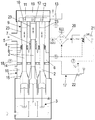
- the single figure shows a plunger pump in a schematic sectional view.
- a plunger pump can be seen, with a housing 1, which has a gear space 3 for receiving a gear, an adjoining space 16, a compensation chamber 6 and a suction space 4.
- a supply line 5 is connected to the latter, via which a fluid under additional pressure can be supplied, in the example a fluid to be homogenized, in particular milk.
- Three plungers 2 are connected to a crankshaft of the transmission (not shown in more detail), namely at an angular offset of 120 °, the plungers 2 being moved in an oscillating manner during operation.
- the plungers 2 can be constructed in several parts.
- plunger 2 For the sake of simplicity, only one plunger 2 is referred to below, since the other plungers are identical in construction and function.
- the plunger 2 is axially displaceably mounted with a head in a guide sleeve 23 of a sealing arrangement 9, which is designed such that a non-contact seal, that is to say a gap seal, results between the plunger 2 and the guide sleeve 23, as is known from the prior art is.
- a working chamber 12 is coaxially assigned to a suction valve 10 and a pressure valve 11, specifically in the area of a pump head 19 closing the housing 1, to which a homogenizing valve 13 corresponding to the pressure valve 11 is connected.
- a bellows 7 on the suction chamber side encloses a partial area of the plunger 2 in the suction chamber 4 and is fastened on the one hand in a sealing manner to the plunger 2 and on the other hand in a sealing manner on a boundary wall 8 which separates the suction chamber 4 from the compensation chamber 6.
- the bellows 7 on the suction space side covers a passage opening of the boundary wall 8 through which the plunger 2 is guided.
- the compensation chamber 6 is filled with a medium, under a pressure which is equal to or less than the fluid pressure in the suction chamber 4, preferably 0.1 bar lower.
- an inert gas is used as the medium, which otherwise causes a counterpressure in the bellows 7 on the suction chamber side to the fluid pressure in the suction chamber 4 which is present on the outside of the bellows 7 on the suction chamber side.
- the space 16 is sealed in the area of the plungers 2 carried out via lip seals 14 with respect to the compensating chamber 6 and with respect to the gear space 3 by a bellows 15 on the space side, so that a redundant triple seal to the gear space 3 is provided to the suction space 4, which effectively prevents that for example, transmission oil gets into the suction chamber 4.
- a leakage detection 18 is provided in the compensation chamber 6, for example a sensor, by means of which a penetration of fluid from the suction chamber 4 through a defective bellows 7 into the compensation chamber 6 can be detected.
- This leakage detection 18 can be carried out by determining a pH value, the conductivity, the fill level, the turbidity or the like. It is also conceivable to arrange several sensors that can be active in parallel.
- a control device 17 which has a differential pressure monitor 20, a controller 21 and a pressure control valve 22 with position monitoring, is connected to the suction chamber 4 on the one hand and to the compensation chamber 6 on the other.
Landscapes
- Engineering & Computer Science (AREA)
- General Engineering & Computer Science (AREA)
- Mechanical Engineering (AREA)
- Life Sciences & Earth Sciences (AREA)
- Animal Husbandry (AREA)
- Environmental Sciences (AREA)
- Details Of Reciprocating Pumps (AREA)
Description
- Die Erfindung betrifft eine Plungerpumpe nach dem Oberbegriff des Anspruchs 1 sowie die Verwendung einer Plungerpumpe.
Derartige Plungerpumpen sind hinlänglich bekannt. Beispielhaft wird auf dieEP 1 260 712 B1 verwiesen, bei der mehrere, d.h. konkret drei Plunger mittels eines Getriebes antreibbar sind, wobei die Plunger um 120° versetzt auf einer Kurbelwelle gelagert sind. Durch diese Plungeranordnung werden dynamische Kräfte ausgeglichen und insbesondere eine Förderstrompulsation verringert.
Zur hermetischen Abdichtung eines Zwischenraumes zu einem Getrieberaum ist ein den Plunger teilweise umhüllender Faltenbalg vorgesehen, der einerseits am Plunger und andererseits an einer Begrenzungswand befestigt ist.
Druckseitig ist der Plunger in einer berührungslosen Dichtungsanordnung geführt, die einen Saugraum von einem Druckraum trennt, wobei einem Pumpenkopf zugeordnet ein Saugventil und ein Druckventil vorgesehen sind.
Prinzipiell hat sich die aus derEP 1 260 712 B1 bekannte Plungerpumpe bewährt.
Für bestimmte Einsatzgebiete, insbesondere für die Homogenisierung von flüssigen Lebensmitteln, beispielsweise von Milch, kommen ebenfalls Plungerpumpen zum Einsatz, deren Plunger in einer berührenden Dichtungsanordnung geführt ist. Eine solche Plungerpumpe ist in derEP 2 941 567 B1 offenbart.
Der Betrieb dieser Plungerpumpe für den genannten Einsatz zeigt sich jedoch als unbefriedigend und vor allem den gestellten hygienischen und aseptischen Ansprüchen nicht gerecht werdend dar.
Durch die berührende Dichtung, bestehend aus mindestens einem am Plunger anliegenden Dichtungsring aus einem relativ weichen Dichtungsmaterial, lösen sich aufgrund der oszillierenden Bewegung des Plungers Abriebspartikel, die in den Saugraum gelangen und damit in die zu homogenisierende Milch. Diese Verunreinigung ist aus hygienischer Sicht nicht akzeptabel und führt letztendlich dazu, dass das Fluid nicht weite verwendet werden kann. - Unabhängig davon ist diese Plungerpumpe so konzipiert, dass der Plunger bei jedem Saughub teilweise in einen septischen Bereich gelangt, wobei sich Keime an der Oberfläche des Plungers anlagern können, die beim folgenden Druckhub mit dem Fluid in Kontakt geraten, so dass auch daraus die Gefahr erwächst, dass die Milch in unzulässiger Weise kontaminiert wird. Um dies zu verhindern, wird der entsprechende Bereich während der gesamten Produktionsdauer mit Dampf oder heißem Kondensat beaufschlagt, was jedoch nur mit einem entsprechend hohen und kostenintensiven Aufwand möglich ist.
- In diesem Sinn problematisch gestaltet sich auch die Reinigung der Plungerpumpe zum Betrieb einer Homogenisiereinrichtung, da hierzu diverse Reinigungsmittel und -gerätschaften bereitgestellt werden müssen. Die Erzeugung von Dampf, gleichermaßen die Reinigung selbst, ist jedoch zeitaufwendig und stellt sich insbesondere in wirtschaftlicher Hinsicht als nachteilig dar, zumal solche Reinigungen in relativ kurzen Intervallen erforderlich sind.
- In der
DE 10 2014 106 520 A1 ist eine Plungerpumpe thematisiert, deren Plunger gegenüber einem räumlich abgetrennten Innenraum jeweils durch einen Faltenbalg hermetisch abgedichtet sind. Allerdings sind diese Faltenbälge, abweichend von der Gattung, nicht einerseits dicht am Plunger und andererseits im Bereich einer Durchführöffnung für den Plunger dicht an einer Begrenzungswand befestigt. - Eine von der Gattung abweichende Plungerpumpe, die keine berührungslose Dichtungsanordnung aufweist, in der der Plunger führbar ist, ist aus der
US 2013/0039788 A1 bekannt. - Ein den Plunger teilweise umhüllender Faltenbalg steht in seinem Innenraum unter Atmosphärendruck und ist offen mit einer Kammer verbunden, die einerseits beim Zusammendrücken des Faltenbalgs bei einer entsprechenden Hubbewegung des Plungers das überschüssige Luftvolumen und andererseits ein aus einem Saugraum bei einer Leckage eintretendes Fluid aufnimmt.
- Der Erfindung liegt die Aufgabe zugrunde, eine Plungerpumpe der gattungsgemäßen Art so weiterzuentwickeln, dass ihre Verwendungsfähigkeit verbessert wird.
- Diese Aufgabe wird durch eine Plungerpumpe mit den Merkmalen des Anspruchs 1 gelöst.
- Die Plungerpumpe gemäß der Erfindung kann nun überall dort eingesetzt werden, wo besondere hygienische Anforderungen an die Förderung eines Fluids bestehen oder wenn umweltproblematische Stoffe gefördert werden. In diesem Fall können durch die neue Ausgestaltung der Plungerpumpe diese Stoffe nicht in die Umgebung gelangen.
- Der entscheidende Vorteil bei der erfindungsgemäßen Plungerpumpe liegt darin, dass der Bereich des Plungers, der funktionsbedingt mit der Umgebung außerhalb des zu fördernden Fluids liegt und von daher kontaminiert werden kann, gegenüber dem im Saugraum befindlichen zu fördernden Fluid mittels Faltenbalg hermetisch abgedichtet ist.
- Damit findet eine solche Plungerpumpe idealerweise in einer Homogenisierungseinrichtung Verwendung.
- Durch die Führung des Plungers in einer berührungslosen Dichtungsanordnung, die bevorzugt als Spaltdichtung gestaltet ist, ist das Entstehen von Abrieb, wie zum Stand der Technik beschrieben, ausgeschlossen.
- Im Übrigen zeichnet sich die Plungerpumpe nach der Erfindung durch eine hohe Lebensdauer der Dichtelemente aus, die erfahrungsgemäß bei > 8000 Betriebsstunden liegt.
- Weiter ist die Leistungsanpassung der Plungerpumpe an den spezifischen Einsatz anzupassen, vor allem hinsichtlich der Hubfrequenz, d.h. der Drehzahl der Kurbelwelle.
- Für den genannten Einsatzzweck weist die berührungslose Dichtungsanordnung eine Führungshülse aus einem zugelassenen korrosionsbeständigen Hartmetall auf. Auch die übrigen Funktionsteile, soweit sie mit dem Fluid in Berührung kommen, sind bevorzugt aus rostfreiem Stahl hergestellt.
- Die Plungerpumpe gemäß der Erfindung zeichnet sich des Weiteren durch ihre kompakte Bauweise aus, mit einem großen Hubvolumen, woraus sich eine Minimierung der Herstellungskosten ergibt beispielsweise gegenüber einer Membranpumpe.
- Nach einem weiteren Gedanken der Erfindung ist die Ausgleichskammer gegenüber einem Antriebsraum, in dem das Getriebe angeordnet ist, abgedichtet, unter Bildung eines Zwischenraumes zwischen der Ausgleichskammer und dem Getrieberaum.
- Der Zwischenraum selbst wiederum kann gegenüber dem Getrieberaum ebenfalls durch einen Faltenbalg abgedichtet sein, der einerseits am Plunger und andererseits an einer Begrenzungswand des Getrieberaums befestigt ist, so dass sich insgesamt eine Dreifachdichtung zwischen dem Getrieberaum und dem Saugraum ergibt, durch die eine Kontamination des im Saugraum befindlichen Fluids durch Schmierstoffe im Getrieberaum ausgeschlossen ist.
- Gemäß der Erfindung ist der Druck des Mediums in der Ausgleichskammer gleich dem Fluidruck im Saugraum oder kleiner ist. Nach einer vorteilhaften Weiterbildung ist der in der Ausgleichskammer herrschende Druck 0,05 - 0,2 bar, vorzugsweise 0,1 bar kleiner als der Zulaufdruck des Fluids.
- Selbst für den Fall, dass der Faltenbalg eine Leckage aufweist, wird das Fluid aufgrund des höheren Drucks in die Ausgleichskammer geleitet, so dass das darin befindliche Medium, bevorzugt ein inertes Gas, z.B. N2, nicht in den Saugraum gelangt, wobei die Ausgleichskammer im Bereich der Durchführung des Plungers mit einer Lippendichtung zum unter Umgebungsdruck stehenden Zwischenraum abgedichtet ist.
- Der dem Saugraum zugeordnete Faltenbalg besteht aus einem thermoplastischen Kunststoff, beispielsweise PTFE, oder einem Elastomerwerkstoff, der sich durch eine besondere Belastbarkeit, insbesondere eine lange Lebensdauer auszeichnet.
- Mittels eines Regelkreises zur Überwachung und Einstellung des Differenzdrucks zwischen der Ausgleichskammer und dem Saugraum, kann eine Funktionsüberwachung des Faltenbalgs erfolgen.
- Bei dessen Bruch kann die vorgegebene Druckdifferenz nicht mehr aufrechterhalten werden, was erfasst wird und zur Abschaltung führt.
- Eine weitere Überwachung in dem dem Zwischenraum benachbarten Bereich der Ausgleichskammer detektiert ein Eindringen des Fluids. Dabei kann die Überwachung über die Erkennung des pH-Werts, der Leitfähigkeit, dem Füllstand, der Trübung oder ähnlichem erfolgen, wobei mehrere entsprechende Sensoren installiert und parallel aktiv sein können.
- Saug- und Druckventilen zugeordnet ist ein Pumpenkopf vorgesehen, an den, bei Verwendung der Plungerpumpe in einer Homogenisiereinrichtung ein Homogenisierventil angeschlossen ist, in dem das unter Druck stehende Fluid zur Homogenisierung entspannt wird.
- Eine Reinigung insbesondere der Spaltdichtung kann mittels Zwangsspülung erfolgen, indem durch das einstellbare Homogenisierventil ein Reinigungsfluid auf einen höheren Druck (50 - 100 bar) als nach dem Stand der Technik (5 - 6 bar) möglich, erzeugt wird. Das Homogenisierventil kann ohne höhere Antriebsleistung durch Drehzahlanhebung der Kurbelwelle wie ein nun nicht mehr erforderlich CIP-Pumpe (cleaning in place) wirken. Der sich einstellende Volumenstrom entspricht dem einer CIP-Pumpe allerdings mit geringerer Antriebsleistung als diese, aufgrund des besseren Wirkungsgrades.
- Die Zwischenräume des Faltenbalges unterliegen einem Selbstreinigungseffekt durch radiale, oszillierende Volumenverdrängung während der Hubbewegung sowie einer geringen Haftneigung an der Oberfläche des vorzugsweise aus einem PTFE-Material bestehenden Faltenbalgs.
- Weitere vorteilhafte Ausbildungen der Erfindung sind in den Unteransprüchen gekennzeichnet.
- Ein Ausführungsbeispiel der erfindungsgemäßen Plungerpumpe wird nachfolgend anhand der beigefügten Zeichnung beschrieben.
- Die einzige Figur zeigt eine Plungerpumpe in einer schematischen Schnittdarstellung.
- In der Figur ist eine Plungerpumpe erkennbar, mit einem Gehäuse 1, das einen Getrieberaum 3 zur Aufnahme eines Getriebes, einen sich daran anschließenden Zwischenraum 16, eine Ausgleichskammer 6 sowie einen Saugraum 4 aufweist. An Letzteren ist eine Zuleitung 5 angeschlossen, über die ein unter Zulaudruck stehendes Fluid zuführbar ist, im Beispiel ein zu homogenisierendes Fluid, insbesondere Milch.
- An einer nicht näher dargestellten Kurbelwelle des Getriebes sind drei Plunger 2 angeschlossen, und zwar in einem Winkelversatz von 120°, wobei die Plunger 2 im Betrieb oszillierend bewegt werden. Wie aus dem Stand der Technik bekannt können die Plunger 2 mehrteilig ausgebildet sein.
- Der Einfachheit halber wird im Folgenden Bezug genommen lediglich auf einen Plunger 2, da die anderen Plunger bau- und funktionsgleich sind.
- Der Plunger 2 ist mit einem Kopf in einer Führungshülse 23 einer Dichtungsanordnung 9 axial verschiebbar gelagert, die derart ausgebildet ist, dass sich zwischen dem Plunger 2 und der Führungshülse 23 eine berührungslose Dichtung, also eine Spaltdichtung ergibt, wie sie aus dem Stand der Technik bekannt ist.
- Einem gebildeten Arbeitsraum 12 sind koaxial ein Saugventil10 und ein Druckventil 11 zugeordnet und zwar im Bereich eines das Gehäuse 1 verschließenden Pumpenkopfes 19, an den ein mit dem Druckventil 11 korrespondierendes Homogenisierventil 13 angeschlossen ist.
- Ein saugraumseitiger Faltenbalg 7 umschließt einen Teilbereich des Plungers 2 im Saugraum 4 und ist einerseits dichtend am Plunger 2 und andererseits dichtend an einer Begrenzungswand 8 befestigt, die den Saugraum 4 von der Ausgleichskammer 6 trennt. Dabei überdeckt der saugraumseitige Faltenbalg 7 eine Durchtrittsöffnung der Begrenzungswand 8, durch die der Plunger 2 geführt ist.
- Gemäß der Erfindung ist die Ausgleichskammer 6 mit einem Medium befüllt, unter einem Druck der gleich oder kleiner ist als der Fluiddruck im Saugraum 4, vorzugsweise 0,1 bar geringer.
- Vorteilhafterweise kommt als Medium ein inertes Gas zum Einsatz, das im Übrigen einen Gegendruck im saugraumseitigen Faltenbalg 7 bewirkt zum Fluiddruck im Saugraum 4, der außenseitig des saugraumseitigen Faltenbalgs 7 anliegt.
- Der Zwischenraum 16 ist im Bereich der durchgeführten Plunger 2 über Lippendichtungen 14 gegenüber der Ausgleichskammer 6 abgedichtet und gegenüber dem Getrieberaum 3 durch einen zwischenraumseitigen Faltenbalg 15, so dass zum Saugraum 4 eine redundante Dreifachdichtung zum Getrieberaum 3 gegeben ist, durch die wirksam verhindert wird, dass beispielsweise Getriebeöl in den Saugraum 4 gelangt.
- Im Bodenbereich, also dem saugraumseitigen Faltenbalg 7 gegenüberliegend, ist in der Ausgleichskammer 6 eine Leckageerkennung 18 vorgesehen, beispielsweise ein Sensor, mittels der ein Eindringen von Fluid aus dem Saugraum 4 durch einen defekten Faltenbalg 7 in die Ausgleichskammer 6 erkennbar ist. Diese Leckageerkennung 18 kann über die Feststellung eines pH-Werts, der Leitfähigkeit, des Füllstandes, der Trübung oder dergleichen erfolgen. Denkbar ist auch die Anordnung mehrerer Sensoren, die parallel aktiv sein können.
- Eine Regeleinrichtung 17, die eine Differenzdrucküberwachung 20, einen Regler 21 sowie ein Druckregelventil 22 mit Lageüberwachung aufweist, ist an den Saugraum 4 einerseits und an die Ausgleichskammer 6 andererseits angeschlossen.
- Im Versagensfall des saugraumseitigen Faltenbalgs 7 findet ein Druckausgleich statt zwischen dem Saugraum 4 und der Ausgleichskammer 6 und die Druckdifferenz, besagte 0,1 bar, kann nicht mehr aufrechterhalten werden, was durch die Regeleinrichtung 17 erfasst wird und zur Abschaltung der Plungerpumpe führt.
-
- 1
- Gehäuse
- 2
- Plunger
- 3
- Getrieberaum
- 4
- Saugraum
- 5
- Zuleitung
- 6
- Ausgleichskammer
- 7
- saugraumseitiger Faltenbalg
- 8
- Begrenzungswand
- 9
- Dichtungsanordnung
- 10
- Saugventil
- 11
- Druckventil
- 12
- Arbeitsraum
- 13
- Homogenisierventil
- 14
- Lippendichtung
- 15
- zwischenraumseitiger Faltenbalg
- 16
- Zwischenraum
- 17
- Regeleinrichtung
- 18
- Leckageerkennung
- 19
- Pumpenkopf
- 20
- Differenzdruck-Überwachung
- 21
- Regler
- 22
- Druckregelventil
- 23
- Führungshülse
Claims (9)
- Plungerpumpe zur Förderung eines Fluids, mit mindestens einem oszillierend antreibbaren Plunger (2), der berührungslos in einer Dichtungsanordnung (9) geführt ist, die einen eine Zuleitung (5) aufweisenden Saugraum (4) von einem Arbeitsraum (12) trennt und einem den Plunger (2) bereichsweise hermetisch umschließenden Faltenbalg (7), der einerseits dicht am Plunger (2) und andererseits im Bereich einer Durchführöffnung für den Plunger (2) dicht an einer Begrenzungswand (8) befestigt ist, dadurch gekennzeichnet, dass dem Saugraum (4) benachbart eine zum inneren des Faltenbalgs (7) offene, in Funktion mit einem unter Druck stehenden Medium gefüllte Ausgleichskammer (6) angeordnet ist, wobei der Mediumdruck gleich oder kleiner ist als der außenseitig auf den Faltenbalg (7) wirkende Zulaufdruck des Fluids.
- Plungerpumpe nach Anspruch 1 oder 2, dadurch gekennzeichnet, dass der Mediumdruck 0,05 bis 0,2 bar, vorzugsweise 0,1 bar, niedriger ist als der im Saugraum (4) herrschende Zulaufdruck des Fluids.
- Plungerpumpe nach einem der vorhergehenden Ansprüche, dadurch gekennzeichnet, dass eine mit dem Saugraum (4) und der Ausgleichskammer (6) in Verbindung stehende Regeleinrichtung (17) vorgesehen ist, mit der eine Differenzüberwachung der Drücke in dem Saugraum (4) und der Ausgleichskammer (6) durchführbar ist.
- Plungerpumpe nach einem der vorhergehenden Ansprüche, dadurch gekennzeichnet, dass mit der Ausgleichskammer (6) eine Leckageerkennung (18) in Wirkverbindung steht, mit der sich verändernde stoffliche Parameter des Mediums erkennbar ist.
- Plungerpumpe nach einem der vorhergehenden Ansprüche, dadurch gekennzeichnet, dass zwischem einen eine Kurbelwelle eines Getriebes aufnehmenden Getrieberaum (3) und der Ausgleichskammer (6) ein Zwischenraum (16) vorgesehen ist, der gegenüber der Ausgleichskammer (6) und dem Getrieberaum (3) abgedichtet ist.
- Plungerpumpe nach einem der vorhergehenden Ansprüche, dadurch gekennzeichnet, dass an einen Pumpenkopf (19), dem ein mit dem Arbeitsraum (12) in Verbindung stehendes Saugventil (10) und ein Druckventil (11) zugeordnet ist, ist ein Homogenisierventil (13) angeschlossen, das mit dem Arbeitsraum (12) über das Druckventil (11) in Verbindung steht.
- Plungerpumpe nach einem der vorhergehenden Ansprüche, dadurch gekennzeichnet, dass mehrere, vorzugsweise drei unter gleichem Winkelabstand zueinander angeordnete Plunger (2) an der Kurbelwelle gehalten sind.
- Plungerpumpe nach einem der vorhergehenden Ansprüche, dadurch gekennzeichnet, dass das Medium in der Ausgleichskammer (6) ein inertes Gas ist.
- Verwendung der Plungerpumpe nach Anspruch 1 zur Druckerhöhung eines Fluids in einer Homogenisiereinrichtung.
Priority Applications (1)
| Application Number | Priority Date | Filing Date | Title |
|---|---|---|---|
| PL18173921T PL3409943T3 (pl) | 2017-06-01 | 2018-05-23 | Pompa nurnikowa i zastosowanie pompy nurnikowej |
Applications Claiming Priority (1)
| Application Number | Priority Date | Filing Date | Title |
|---|---|---|---|
| DE102017112110.2A DE102017112110A1 (de) | 2017-06-01 | 2017-06-01 | Plungerpumpe sowie Verwendung einer Plungerpumpe |
Publications (2)
| Publication Number | Publication Date |
|---|---|
| EP3409943A1 EP3409943A1 (de) | 2018-12-05 |
| EP3409943B1 true EP3409943B1 (de) | 2020-08-05 |
Family
ID=62244349
Family Applications (1)
| Application Number | Title | Priority Date | Filing Date |
|---|---|---|---|
| EP18173921.0A Active EP3409943B1 (de) | 2017-06-01 | 2018-05-23 | Plungerpumpe sowie verwendung einer plungerpumpe |
Country Status (4)
| Country | Link |
|---|---|
| EP (1) | EP3409943B1 (de) |
| DE (1) | DE102017112110A1 (de) |
| ES (1) | ES2821406T3 (de) |
| PL (1) | PL3409943T3 (de) |
Families Citing this family (2)
| Publication number | Priority date | Publication date | Assignee | Title |
|---|---|---|---|---|
| DE102018120582A1 (de) * | 2018-08-23 | 2020-02-27 | Schwing Gmbh | Kolbenpumpe für Dickstoffe mit Wasserkasten |
| CN111677642B (zh) * | 2020-06-23 | 2025-08-22 | 追觅科技(上海)有限公司 | 一种摆动泵、具有其的自混合发泡装置及洗手机 |
Family Cites Families (6)
| Publication number | Priority date | Publication date | Assignee | Title |
|---|---|---|---|---|
| GB656498A (en) * | 1948-10-05 | 1951-08-22 | Jean Lavigne | Fluid compressors |
| US4556369A (en) * | 1982-08-13 | 1985-12-03 | Anton Braun | Bellows seal |
| DE10125669B4 (de) | 2001-05-25 | 2006-04-27 | Hammelmann Maschinenfabrik Gmbh | Pumpe, insbesondere Plungerpumpe |
| WO2011137143A1 (en) * | 2010-04-30 | 2011-11-03 | Graco Minnesota Inc. | Bellows backup chamber |
| US20160215773A1 (en) | 2012-12-21 | 2016-07-28 | Tetra Laval Holdings & Finance S.A. | Piston and use of such piston |
| DE102014106520A1 (de) * | 2014-05-09 | 2015-11-12 | Hammelmann Maschinenfabrik Gmbh | Hochdruck-Plungerpumpe |
-
2017
- 2017-06-01 DE DE102017112110.2A patent/DE102017112110A1/de not_active Withdrawn
-
2018
- 2018-05-23 PL PL18173921T patent/PL3409943T3/pl unknown
- 2018-05-23 EP EP18173921.0A patent/EP3409943B1/de active Active
- 2018-05-23 ES ES18173921T patent/ES2821406T3/es active Active
Non-Patent Citations (1)
| Title |
|---|
| None * |
Also Published As
| Publication number | Publication date |
|---|---|
| PL3409943T3 (pl) | 2020-12-14 |
| DE102017112110A1 (de) | 2018-12-06 |
| EP3409943A1 (de) | 2018-12-05 |
| ES2821406T3 (es) | 2021-04-26 |
Similar Documents
| Publication | Publication Date | Title |
|---|---|---|
| EP3090196A1 (de) | Ventil | |
| EP0789147A2 (de) | Hochdruckplungerpumpe, vorzugsweise für Arbeitsdrücke oberhalb 2.000 bar | |
| WO2015078487A1 (de) | Dosier- und förderpumpe für chemisch aggressive und/oder abrasive fluide | |
| EP2969895A1 (de) | Mediendrehverteiler für gefässfüllmaschinen | |
| DE4019746C1 (de) | ||
| EP3246568A1 (de) | Pumpenanordnung | |
| EP1260712A2 (de) | Pumpe, insbesondere Plungerpumpe | |
| EP3409943A1 (de) | Plungerpumpe sowie verwendung einer plungerpumpe | |
| EP2123359A1 (de) | Pipettiervorrichung zur Aspiration und Dispensation eines Dosierfluids | |
| EP3371458B1 (de) | Trockenvakuumpumpe | |
| EP2949930B1 (de) | Kolben für eine dosierpumpe | |
| DE102014000469B4 (de) | Schraubenverdichter | |
| DE202008016113U1 (de) | Aseptisches Rückschlagventil, insbesondere Tellerrückschlagventil | |
| EP2730821A1 (de) | Vorrichtung und Verfahren zum Abdichten eines Maschinenteils gegenüber einem zweiten Maschinenteil | |
| WO2006005330A1 (de) | Dichtungsanordnung | |
| DE102005045937A1 (de) | Kolbenpumpe für eine Schlupfregelung aufweisende Fahrzeugbremsanlage | |
| DE19603070A1 (de) | Prozeßventil, insbesondere für die sterile Verfahrenstechnik | |
| EP3227555A1 (de) | Längenausgleichsvorrichtung | |
| EP1417430B1 (de) | Membranventil | |
| EP3441612A1 (de) | Pumpen-einheit, damit ausgestattete lagervorrichtung sowie verfahren zum betreiben der lagervorrichtung | |
| EP1703185B1 (de) | Coaxialventil | |
| EP3701091B1 (de) | Schlitzwandfräse | |
| DE29507638U1 (de) | Ventil | |
| DE102020121486B3 (de) | Druckmittelzylinder mit statischer Endlagendichtung | |
| DE102019201847A1 (de) | Hochdruckpumpe, Pumpenkolben und Verfahren zum Homogenisieren |
Legal Events
| Date | Code | Title | Description |
|---|---|---|---|
| PUAI | Public reference made under article 153(3) epc to a published international application that has entered the european phase |
Free format text: ORIGINAL CODE: 0009012 |
|
| STAA | Information on the status of an ep patent application or granted ep patent |
Free format text: STATUS: THE APPLICATION HAS BEEN PUBLISHED |
|
| AK | Designated contracting states |
Kind code of ref document: A1 Designated state(s): AL AT BE BG CH CY CZ DE DK EE ES FI FR GB GR HR HU IE IS IT LI LT LU LV MC MK MT NL NO PL PT RO RS SE SI SK SM TR |
|
| AX | Request for extension of the european patent |
Extension state: BA ME |
|
| STAA | Information on the status of an ep patent application or granted ep patent |
Free format text: STATUS: REQUEST FOR EXAMINATION WAS MADE |
|
| 17P | Request for examination filed |
Effective date: 20190604 |
|
| RBV | Designated contracting states (corrected) |
Designated state(s): AL AT BE BG CH CY CZ DE DK EE ES FI FR GB GR HR HU IE IS IT LI LT LU LV MC MK MT NL NO PL PT RO RS SE SI SK SM TR |
|
| REG | Reference to a national code |
Ref country code: DE Ref legal event code: R079 Ref document number: 502018002070 Country of ref document: DE Free format text: PREVIOUS MAIN CLASS: F04B0001040000 Ipc: F04B0001040800 |
|
| GRAP | Despatch of communication of intention to grant a patent |
Free format text: ORIGINAL CODE: EPIDOSNIGR1 |
|
| STAA | Information on the status of an ep patent application or granted ep patent |
Free format text: STATUS: GRANT OF PATENT IS INTENDED |
|
| RIC1 | Information provided on ipc code assigned before grant |
Ipc: F04B 1/0448 20200101ALI20200221BHEP Ipc: F16J 15/52 20060101ALI20200221BHEP Ipc: A01J 11/16 20060101ALI20200221BHEP Ipc: B01F 15/02 20060101ALI20200221BHEP Ipc: F04B 15/00 20060101ALI20200221BHEP Ipc: F04B 1/0408 20200101AFI20200221BHEP Ipc: F04B 53/14 20060101ALI20200221BHEP |
|
| INTG | Intention to grant announced |
Effective date: 20200323 |
|
| GRAS | Grant fee paid |
Free format text: ORIGINAL CODE: EPIDOSNIGR3 |
|
| GRAA | (expected) grant |
Free format text: ORIGINAL CODE: 0009210 |
|
| STAA | Information on the status of an ep patent application or granted ep patent |
Free format text: STATUS: THE PATENT HAS BEEN GRANTED |
|
| AK | Designated contracting states |
Kind code of ref document: B1 Designated state(s): AL AT BE BG CH CY CZ DE DK EE ES FI FR GB GR HR HU IE IS IT LI LT LU LV MC MK MT NL NO PL PT RO RS SE SI SK SM TR |
|
| REG | Reference to a national code |
Ref country code: GB Ref legal event code: FG4D Free format text: NOT ENGLISH |
|
| REG | Reference to a national code |
Ref country code: CH Ref legal event code: EP |
|
| REG | Reference to a national code |
Ref country code: AT Ref legal event code: REF Ref document number: 1299063 Country of ref document: AT Kind code of ref document: T Effective date: 20200815 |
|
| REG | Reference to a national code |
Ref country code: DE Ref legal event code: R096 Ref document number: 502018002070 Country of ref document: DE |
|
| REG | Reference to a national code |
Ref country code: IE Ref legal event code: FG4D Free format text: LANGUAGE OF EP DOCUMENT: GERMAN |
|
| REG | Reference to a national code |
Ref country code: CH Ref legal event code: NV Representative=s name: ISLER AND PEDRAZZINI AG, CH |
|
| REG | Reference to a national code |
Ref country code: NL Ref legal event code: FP |
|
| REG | Reference to a national code |
Ref country code: FI Ref legal event code: FGE |
|
| REG | Reference to a national code |
Ref country code: LT Ref legal event code: MG4D |
|
| REG | Reference to a national code |
Ref country code: NO Ref legal event code: T2 Effective date: 20200805 |
|
| PG25 | Lapsed in a contracting state [announced via postgrant information from national office to epo] |
Ref country code: SE Free format text: LAPSE BECAUSE OF FAILURE TO SUBMIT A TRANSLATION OF THE DESCRIPTION OR TO PAY THE FEE WITHIN THE PRESCRIBED TIME-LIMIT Effective date: 20200805 Ref country code: GR Free format text: LAPSE BECAUSE OF FAILURE TO SUBMIT A TRANSLATION OF THE DESCRIPTION OR TO PAY THE FEE WITHIN THE PRESCRIBED TIME-LIMIT Effective date: 20201106 Ref country code: LT Free format text: LAPSE BECAUSE OF FAILURE TO SUBMIT A TRANSLATION OF THE DESCRIPTION OR TO PAY THE FEE WITHIN THE PRESCRIBED TIME-LIMIT Effective date: 20200805 Ref country code: BG Free format text: LAPSE BECAUSE OF FAILURE TO SUBMIT A TRANSLATION OF THE DESCRIPTION OR TO PAY THE FEE WITHIN THE PRESCRIBED TIME-LIMIT Effective date: 20201105 Ref country code: PT Free format text: LAPSE BECAUSE OF FAILURE TO SUBMIT A TRANSLATION OF THE DESCRIPTION OR TO PAY THE FEE WITHIN THE PRESCRIBED TIME-LIMIT Effective date: 20201207 Ref country code: HR Free format text: LAPSE BECAUSE OF FAILURE TO SUBMIT A TRANSLATION OF THE DESCRIPTION OR TO PAY THE FEE WITHIN THE PRESCRIBED TIME-LIMIT Effective date: 20200805 |
|
| PG25 | Lapsed in a contracting state [announced via postgrant information from national office to epo] |
Ref country code: LV Free format text: LAPSE BECAUSE OF FAILURE TO SUBMIT A TRANSLATION OF THE DESCRIPTION OR TO PAY THE FEE WITHIN THE PRESCRIBED TIME-LIMIT Effective date: 20200805 Ref country code: RS Free format text: LAPSE BECAUSE OF FAILURE TO SUBMIT A TRANSLATION OF THE DESCRIPTION OR TO PAY THE FEE WITHIN THE PRESCRIBED TIME-LIMIT Effective date: 20200805 Ref country code: IS Free format text: LAPSE BECAUSE OF FAILURE TO SUBMIT A TRANSLATION OF THE DESCRIPTION OR TO PAY THE FEE WITHIN THE PRESCRIBED TIME-LIMIT Effective date: 20201205 |
|
| REG | Reference to a national code |
Ref country code: ES Ref legal event code: FG2A Ref document number: 2821406 Country of ref document: ES Kind code of ref document: T3 Effective date: 20210426 |
|
| PG25 | Lapsed in a contracting state [announced via postgrant information from national office to epo] |
Ref country code: RO Free format text: LAPSE BECAUSE OF FAILURE TO SUBMIT A TRANSLATION OF THE DESCRIPTION OR TO PAY THE FEE WITHIN THE PRESCRIBED TIME-LIMIT Effective date: 20200805 Ref country code: DK Free format text: LAPSE BECAUSE OF FAILURE TO SUBMIT A TRANSLATION OF THE DESCRIPTION OR TO PAY THE FEE WITHIN THE PRESCRIBED TIME-LIMIT Effective date: 20200805 Ref country code: CZ Free format text: LAPSE BECAUSE OF FAILURE TO SUBMIT A TRANSLATION OF THE DESCRIPTION OR TO PAY THE FEE WITHIN THE PRESCRIBED TIME-LIMIT Effective date: 20200805 Ref country code: EE Free format text: LAPSE BECAUSE OF FAILURE TO SUBMIT A TRANSLATION OF THE DESCRIPTION OR TO PAY THE FEE WITHIN THE PRESCRIBED TIME-LIMIT Effective date: 20200805 Ref country code: SM Free format text: LAPSE BECAUSE OF FAILURE TO SUBMIT A TRANSLATION OF THE DESCRIPTION OR TO PAY THE FEE WITHIN THE PRESCRIBED TIME-LIMIT Effective date: 20200805 |
|
| REG | Reference to a national code |
Ref country code: DE Ref legal event code: R097 Ref document number: 502018002070 Country of ref document: DE |
|
| PG25 | Lapsed in a contracting state [announced via postgrant information from national office to epo] |
Ref country code: AL Free format text: LAPSE BECAUSE OF FAILURE TO SUBMIT A TRANSLATION OF THE DESCRIPTION OR TO PAY THE FEE WITHIN THE PRESCRIBED TIME-LIMIT Effective date: 20200805 |
|
| PLBE | No opposition filed within time limit |
Free format text: ORIGINAL CODE: 0009261 |
|
| STAA | Information on the status of an ep patent application or granted ep patent |
Free format text: STATUS: NO OPPOSITION FILED WITHIN TIME LIMIT |
|
| PG25 | Lapsed in a contracting state [announced via postgrant information from national office to epo] |
Ref country code: SK Free format text: LAPSE BECAUSE OF FAILURE TO SUBMIT A TRANSLATION OF THE DESCRIPTION OR TO PAY THE FEE WITHIN THE PRESCRIBED TIME-LIMIT Effective date: 20200805 |
|
| 26N | No opposition filed |
Effective date: 20210507 |
|
| PG25 | Lapsed in a contracting state [announced via postgrant information from national office to epo] |
Ref country code: SI Free format text: LAPSE BECAUSE OF FAILURE TO SUBMIT A TRANSLATION OF THE DESCRIPTION OR TO PAY THE FEE WITHIN THE PRESCRIBED TIME-LIMIT Effective date: 20200805 |
|
| PG25 | Lapsed in a contracting state [announced via postgrant information from national office to epo] |
Ref country code: MC Free format text: LAPSE BECAUSE OF FAILURE TO SUBMIT A TRANSLATION OF THE DESCRIPTION OR TO PAY THE FEE WITHIN THE PRESCRIBED TIME-LIMIT Effective date: 20200805 Ref country code: LU Free format text: LAPSE BECAUSE OF NON-PAYMENT OF DUE FEES Effective date: 20210523 |
|
| REG | Reference to a national code |
Ref country code: BE Ref legal event code: MM Effective date: 20210531 |
|
| PG25 | Lapsed in a contracting state [announced via postgrant information from national office to epo] |
Ref country code: IE Free format text: LAPSE BECAUSE OF NON-PAYMENT OF DUE FEES Effective date: 20210523 |
|
| PG25 | Lapsed in a contracting state [announced via postgrant information from national office to epo] |
Ref country code: BE Free format text: LAPSE BECAUSE OF NON-PAYMENT OF DUE FEES Effective date: 20210531 |
|
| PG25 | Lapsed in a contracting state [announced via postgrant information from national office to epo] |
Ref country code: CY Free format text: LAPSE BECAUSE OF FAILURE TO SUBMIT A TRANSLATION OF THE DESCRIPTION OR TO PAY THE FEE WITHIN THE PRESCRIBED TIME-LIMIT Effective date: 20200805 |
|
| PG25 | Lapsed in a contracting state [announced via postgrant information from national office to epo] |
Ref country code: HU Free format text: LAPSE BECAUSE OF FAILURE TO SUBMIT A TRANSLATION OF THE DESCRIPTION OR TO PAY THE FEE WITHIN THE PRESCRIBED TIME-LIMIT; INVALID AB INITIO Effective date: 20180523 |
|
| PG25 | Lapsed in a contracting state [announced via postgrant information from national office to epo] |
Ref country code: MK Free format text: LAPSE BECAUSE OF FAILURE TO SUBMIT A TRANSLATION OF THE DESCRIPTION OR TO PAY THE FEE WITHIN THE PRESCRIBED TIME-LIMIT Effective date: 20200805 |
|
| PG25 | Lapsed in a contracting state [announced via postgrant information from national office to epo] |
Ref country code: MT Free format text: LAPSE BECAUSE OF FAILURE TO SUBMIT A TRANSLATION OF THE DESCRIPTION OR TO PAY THE FEE WITHIN THE PRESCRIBED TIME-LIMIT Effective date: 20200805 |
|
| PGFP | Annual fee paid to national office [announced via postgrant information from national office to epo] |
Ref country code: NO Payment date: 20260316 Year of fee payment: 9 |
|
| PGFP | Annual fee paid to national office [announced via postgrant information from national office to epo] |
Ref country code: PL Payment date: 20260312 Year of fee payment: 9 |
|
| PGFP | Annual fee paid to national office [announced via postgrant information from national office to epo] |
Ref country code: NL Payment date: 20260410 Year of fee payment: 9 |
|
| REG | Reference to a national code |
Ref country code: CH Ref legal event code: U11 Free format text: ST27 STATUS EVENT CODE: U-0-0-U10-U11 (AS PROVIDED BY THE NATIONAL OFFICE) Effective date: 20260601 |
|
| PGFP | Annual fee paid to national office [announced via postgrant information from national office to epo] |
Ref country code: ES Payment date: 20260618 Year of fee payment: 9 |
|
| PGFP | Annual fee paid to national office [announced via postgrant information from national office to epo] |
Ref country code: GB Payment date: 20260521 Year of fee payment: 9 |
|
| PGFP | Annual fee paid to national office [announced via postgrant information from national office to epo] |
Ref country code: IT Payment date: 20260529 Year of fee payment: 9 |
|
| PGFP | Annual fee paid to national office [announced via postgrant information from national office to epo] |
Ref country code: DE Payment date: 20260317 Year of fee payment: 9 |
|
| PGFP | Annual fee paid to national office [announced via postgrant information from national office to epo] |
Ref country code: AT Payment date: 20260522 Year of fee payment: 9 Ref country code: FI Payment date: 20260521 Year of fee payment: 9 |
|
| PGFP | Annual fee paid to national office [announced via postgrant information from national office to epo] |
Ref country code: CH Payment date: 20260601 Year of fee payment: 9 |
|
| PGFP | Annual fee paid to national office [announced via postgrant information from national office to epo] |
Ref country code: TR Payment date: 20260515 Year of fee payment: 9 |
|
| PGFP | Annual fee paid to national office [announced via postgrant information from national office to epo] |
Ref country code: FR Payment date: 20260521 Year of fee payment: 9 |