EP1260712B1 - Pumpe, insbesondere Plungerpumpe - Google Patents
Pumpe, insbesondere Plungerpumpe Download PDFInfo
- Publication number
- EP1260712B1 EP1260712B1 EP02004477A EP02004477A EP1260712B1 EP 1260712 B1 EP1260712 B1 EP 1260712B1 EP 02004477 A EP02004477 A EP 02004477A EP 02004477 A EP02004477 A EP 02004477A EP 1260712 B1 EP1260712 B1 EP 1260712B1
- Authority
- EP
- European Patent Office
- Prior art keywords
- plunger
- pump
- sealing means
- casing
- space
- Prior art date
- Legal status (The legal status is an assumption and is not a legal conclusion. Google has not performed a legal analysis and makes no representation as to the accuracy of the status listed.)
- Expired - Lifetime
Links
- 238000007789 sealing Methods 0.000 claims abstract description 20
- 239000012530 fluid Substances 0.000 claims description 12
- 239000000565 sealant Substances 0.000 description 5
- 230000008901 benefit Effects 0.000 description 4
- 239000000463 material Substances 0.000 description 3
- XLYOFNOQVPJJNP-UHFFFAOYSA-N water Substances O XLYOFNOQVPJJNP-UHFFFAOYSA-N 0.000 description 3
- 238000005461 lubrication Methods 0.000 description 2
- 238000012856 packing Methods 0.000 description 2
- 238000005086 pumping Methods 0.000 description 2
- 239000000919 ceramic Substances 0.000 description 1
- 230000001010 compromised effect Effects 0.000 description 1
- 238000006073 displacement reaction Methods 0.000 description 1
- 229920001971 elastomer Polymers 0.000 description 1
- 239000000806 elastomer Substances 0.000 description 1
- 238000005516 engineering process Methods 0.000 description 1
- 230000007613 environmental effect Effects 0.000 description 1
- 239000002360 explosive Substances 0.000 description 1
- 239000012528 membrane Substances 0.000 description 1
- 239000002184 metal Substances 0.000 description 1
- 238000000926 separation method Methods 0.000 description 1
- 239000007787 solid Substances 0.000 description 1
- 239000000126 substance Substances 0.000 description 1
- 231100000331 toxic Toxicity 0.000 description 1
- 230000002588 toxic effect Effects 0.000 description 1
Images


Classifications
-
- F—MECHANICAL ENGINEERING; LIGHTING; HEATING; WEAPONS; BLASTING
- F04—POSITIVE - DISPLACEMENT MACHINES FOR LIQUIDS; PUMPS FOR LIQUIDS OR ELASTIC FLUIDS
- F04B—POSITIVE-DISPLACEMENT MACHINES FOR LIQUIDS; PUMPS
- F04B53/00—Component parts, details or accessories not provided for in, or of interest apart from, groups F04B1/00 - F04B23/00 or F04B39/00 - F04B47/00
- F04B53/14—Pistons, piston-rods or piston-rod connections
- F04B53/143—Sealing provided on the piston
Definitions
- the present invention includes a pump, in particular a plunger pump, with a crank mechanism which oscillates a plunger disposed in a housing and guided in a receptacle, and a pump head fixed to the housing for directing the pressurized fluid, the housing housing the crank mechanism and surrounding the plunger.
- plunger pumps which are used in particular in high-pressure water technology, as they are compact and can be used reliably at pressures between 100 and 3000 bar. These plunger pumps have the advantage of good energy efficiency over other types of pump, such as rotary positive displacement pumps, and are capable of handling even difficult fluid conditions, such as high temperature, low and high viscosity media, and solids laden fluids.
- the plunger pumps have a relatively quiet and low-vibration run and are easy to maintain.
- a disadvantage of these vertically arranged plunger pumps is that oil is present in the lower housing part with the crank mechanism, so that this housing area must be mounted relative to the upper housing area by means of appropriate wipers or a suction chamber seal which is expensive to install. For this purpose, the surface of the piston rod must be machined to accommodate a entprechenden seal.
- the U.S. 4,087,213 discloses a plunger pump in which a plunger is oscillated and a bellows provides a seal between a housing and the plunger.
- this plunger pump can not be used for higher pressures, since the seal of the plunger and the bellows seal are mechanically not designed for such loads.
- the FR 227 39 61 shows a diaphragm pump, in which a diaphragm is fixed to a piston.
- the piston is guided displaceably on a seal. This design is not suitable for higher pressures and aggressive media.
- a combined plunger and diaphragm pump is known in which a housing space with a crank mechanism via a membrane from the fluid-conducting portion is separated with a plunger.
- the fluid under pressure can enter the housing space with the crank mechanism.
- the plunger elastic elastic sealants are fixed, which provide a pressure-tight seal to a lower crankcase containing housing space, the plunger or attached to the plunger vertical sealing and guiding element need not be performed with particular precision in a recording to a Seal to produce the upper housing part. It can, for example, account for a processing of the surface of the plunger rod for sealing ring receptacles or a sliding ring or Simmering can be saved.
- the elastic sealing means serve as splash protection in order to prevent the entry of oil from the region of the crank mechanism into the upper housing part.
- Such a hermetic seal of the lower housing part offers particular advantages for chemical pumps, since such a media and water jet resistant seal was previously possible only with diaphragm pumps.
- a gap is formed in the housing above the lower housing space and below the pump head. This space is filled with air. There is a clear separation between one Fluid space in the pump head, the space filled with air and the space of the crank mechanism containing oil.
- the sealant is fixed on one side to the plunger and on the opposite side to the housing.
- the assembly is facilitated when inner webs are formed on the housing, which surround the plunger in an annular shape, so that the sealing means are clamped only on this housing section.
- the sealing means may be formed as an annular or conical bellows.
- a conical design of the bellows has the advantage that buckling is prevented.
- the waves provided on the bellows should be provided in such a number that no flutter occurs even at high stroke frequencies. With a gas-tight design of the sealant, the pump can be used in an extreme environment.
- the plunger can be designed in several parts in order to be able to clamp the sealant to a lower plunger element.
- In the upper area of the plunger is piston-shaped accommodated in a bushing or receptacle for the Plungerabdichtung.
- the pump has a plurality of adjacent plungers, wherein sealing means are provided around each plunger to a lower housing space.
- the plurality of plungers may then be combined to form a common pumping unit to provide a large delivery volume.
- the pump is designed as Hochdruckplungerpumpe.
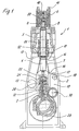
- plunger pump 1 comprises a single or multi-part housing 2 in which a lower crank mechanism 3 is provided.
- the crank mechanism 3 serves to drive a plunger 5, which is designed in several parts and comprises a lower plunger section 4.
- the plunger 5 is made of highly wear-resistant material, such as ceramic or hard metal and slides without pressing in a running sleeve or receptacle 51, not shown, for sealing the annular gap formed around the plunger 5.
- This receptacle 51 forms a high pressure seal and may be formed as a labyrinth, packing or hydrodynamic seal.
- a low pressure seal 52 is provided, which is designed as a packing or elastomer sealing ring. Due to the vertical structure, the plunger pump 1 can operate without weight.
- a pump head 6 is provided in the upper region, are formed in the channels for conducting a fluid.
- the pump head 6 is fastened to the housing 2 via bolts 11.
- a fluid For pumping a fluid is sucked from a suction chamber 9 in a downward movement of the plunger 5 fluid in the space 8. Once the plunger 5 has passed through the lowest point, the plunger 5 moves upward and closes via a valve access to the suction chamber 9. Further, a valve 50 is actuated that opens an access to a pressure chamber 10. By moving the plunger 5 upward, the fluid is thus pumped into the pressure chamber 10 and distributed via corresponding lines from generation of a certain pressure.
- an annular and conically shaped bellows 7 is provided for sealing between a lower housing space 19, in which the crank mechanism 3 is arranged, and a space 12 filled with air. Due to the conical and wavy design of the bellows 7 buckling in the movement of the plunger 5 is prevented.
- the bellows 7 is fixed on one side to the plunger 5, wherein on the lower plunger portion 4, a flange 43 is provided, on which an annular portion 14 is clamped tightly via a clamping element 15.
- On the opposite side of the bellows 7 is sealingly fixed to an annular receptacle 17 via further clamping elements.
- the receptacle 17 is integrally connected to the housing 2 via inner webs.
- the bellows 7 is formed of a media-resistant and water jet resistant material, so that the pump 1 can be used even under extreme conditions.
- the wall thickness of the flexible material of the bellows 7 is about 1 to 2 mm.
- a plurality of plungers 5 are arranged side by side.
- the crank mechanism 3 is driven via a pinion shaft 30, the pinion mesh with one or more gears 29.
- the gears 29 are connected to a crankshaft, wherein an oscillating movement of the plunger 5 is generated by the eccentric attachment of the connecting rod.
- a guide element 21 is articulated on an axle 22 on the connecting rod 32.
- an oil pressure circulation lubrication is provided in the lower housing space 19, an oil pressure circulation lubrication is provided.
- the guide element 21 is guided in a receptacle 20, wherein between 20 guide member 21 and receptacle no expensive sealing means must be provided, since the bellows 7 provides a hermetic seal and forms a splash guard. This type of elastic sealing by the bellows 7 also prevents wear of sealants, such as sliding guides etc.
- 3 plungers are mounted in the housing 2 in the embodiment shown. It is also possible to combine fewer or more plungers 5 in one pump unit.
- the lower plunger portion 4 comprises a flange 43 for fixing the bellows 7.
- a stop 44 is provided for connection to the upper part of the plunger 5.
- a pin 41 is formed, which engages in the guide element 21.
- the pin 41 has a reduced diameter, so that pressure forces can be removed from the guide member 21 via a shoulder 42.
Landscapes
- Engineering & Computer Science (AREA)
- Mechanical Engineering (AREA)
- General Engineering & Computer Science (AREA)
- Details Of Reciprocating Pumps (AREA)
- Reciprocating Pumps (AREA)
- Compressor (AREA)
- Compressors, Vaccum Pumps And Other Relevant Systems (AREA)
Description
- Die vorliegende Erfindung bebrifft eine Pumpe, insbesondere eine Plungerpumpe, mit einem Kurbeltrieb, der einen in einem Gehäuse angeordneten und in einer Aufnahme geführten Plunger oszillierend antreibt, und einem an dem Gehäuse festgelegten Pumpenkopf zur Leitung des mit Druck beaufschlagten Fluids, wobei das Gehäuse den Kurbeltrieb und den Plunger umgibt.
- Es gibt Plungerpumpen, die insbesondere in der Hochdruckwassertechnik eingesetzt werden, da diese kompakt sind und betriebssicher bei Drücken zwischen 100 und 3000 bar eingesetzt werden können. Diese Plungerpumpen besitzen gegenüber anderen Pumpenbauarten, wie rotierenden Verdrängerpumpen den Vorteil eines guten energetischen Wirkungsgrades und sind in der Lage, auch schwierige Fluidbedingungen, wie hohe Temperatur, niedrig- und hochviskose Medien sowie feststoffbeladene Flüssigkeiten zu fördern. Die Plungerpumpen besitzen einen relativ ruhigen und schwingungsarmen Lauf und sind einfach zu warten. Nachteilig bei diesen vertikal angeordneten Plungerpumpen ist, dass in dem unteren Gehäuseteil mit dem Kurbeltrieb Öl vorhanden ist, so dass dieser Gehäusebereich gegenüber dem oberen Gehäusebereich durch entsprechende Abstreifer oder eine aufwendig zu installierende Saugraumabdichtung montiert werden muß. Hierfür muß die Oberfläche der Kolbenstange bearbeitet werden, um einen entprechenden Dichtring aufzunehmen.
- Die
US 4 087 213 offenbart eine Plungerpumpe, bei der ein Plunger oszillierend geführt ist und ein Faltenbalg eine Abdichtung zwischen einem Gehäuse und dem Plunger bereitstellt. Diese Plungerpumpe ist jedoch nicht für höherere Drücke einsetzbar, da die Abdichtung des Plungers und die Faltenbalgdichtung für solche Belastungen mechanisch nicht ausgelegt sind. - Die
FR 227 39 61 - Aus der
GB 1 414 675 - Es ist daher Aufgabe der vorliegenden Erfindung, eine Pumpe, insbesondere eine Plungerpumpe der eingangs genannten Art zu schaffen, bei der auf einfache Weise eine zuverlässige Abdichtung zu dem unteren den Kurbeltrieb enthaltenden Gehäuseraum bereitgestellt wird und die auch unter extremen Umgebungsbedingungen einsetzbar ist.
- Diese Aufgabe wird mit einer Pumpe mit den Merkmalen des Anspruches 1 gelöst.
- Wenn am Plunger elastische Dichtmittel festgelegt sind, die eine druckdichte Abdichtung zu einem unteren den Kurbeltrieb enthaltenden Gehäuseraum bereitstellen, braucht der Plunger bzw. ein am Plunger befestigtes vertikales Dichtungs- und Führungselement nicht mehr mit besonders hoher Präzision in einer Aufnahme geführt zu sein, um eine Abdichtung zu dem oberen Gehäuseteil zu erzeugen. Es kann beispielsweise auf eine Bearbeitung der Oberfläche der Plungerstange für Dichtringaufnahmen entfallen oder ein Gleitring oder Simmering kann eingespart werden. Die elastischen Dichtmittel dienen dabei unter anderem als Spritzschutz, um einen Eintritt von Öl aus dem Bereich des Kurbeltriebes in den oberen Gehäuseteil zu vermeiden. Eine solche hermetische Abdichtung des unteren Gehäuseteils bietet insbesondere Vorteile für Chemiepumpen, da eine solche medien- und wasserstrahlbeständige Abdichtung bisher nur mit Membranpumpen möglich war. Insbesondere wenn das zu fördernde Fluid schmutzbeladen, giftig, gesundheitsschädlich, korrosiv, explosiv oder brennbar ist, kommen die Vorteile der hermetischen Abdichtung zum Tragen. Wenn das Fluid schlecht schmierend ist, könnte ohne eine entsprechende Abdichtung eine Triebwerksschmierung beeinträchtigt werden.
- Gemäß der Erfindung ist in dem Gehäuse ein Zwischenraum oberhalb des unteren Gehäuseraumes und unterhalb des Pumpenkopfes ausgebildet. Dieser Zwischenräum ist mit Luft gefüllt. Damit besteht eine klare Trennung zwischen einem Fluidraum im Pumpenkopf, dem Zwischenraum, der mit Luft gefüllt ist und dem Raum des Kurbeltriebes, in dem Öl enthalten ist.
- Vorzugsweise ist das Dichtmittel auf der einen Seite am Plunger und auf der gegenüberliegenden Seite am Gehäuse festgelegt. Die Montage wird dabei erleichtert, wenn an dem Gehäuse Innenstege ausgebildet sind, die den Plunger ringförmig umgeben, so dass die Dichtmittel lediglich auf diesen Gehäuseabschnitt aufgeklemmt werden. Um eine ausreichende Elastizität für die Bewegung des Plungers zu besitzen, kann das Dichtmittel als ringförmiger oder konischer Faltenbalg ausgebildet sein. Eine konische Ausbildung des Faltenbalgs hat den Vorteil, dass ein Ausknicken verhindert wird. Die an dem Faltenbalg vorgesehenen Wellen sollten in einer solchen Anzahl vorgesehen werden, dass auch bei hohen Hubfrequenzen kein Flattern auftritt. Bei einer gasdichten Ausbildung der Dichtmittel kann die Pumpe in einer extremen Umgebung eingesetzt werden.
- Der Plunger kann mehrteilig ausgebildet sein, um das Dichtmittel an einem unteren Plungerelement festklemmen zu können. Im oberen Bereich ist der Plunger kolbenförmig in einer Buchse bzw. Aufnahme für die Plungerabdichtung aufgenommen.
- Gemäß einer weiteren Ausführungsform der Erfindung weist die Pumpe mehrere benachbarte Plunger auf, wobei um jeden Plunger Dichtmittel zu einem unteren Gehäuseraum vorgesehen sind. Die mehreren Plunger können dann zu einer gemeinsamen Pumpeinheit zusammengefasst sein, um ein großes Fördervolumen bereitzustellen. Vorzugsweise ist daher die Pumpe als Hochdruckplungerpumpe ausgebildet.
- Die Erfindung wird nachfolgend anhand eines Ausführungsbeispieles mit Bezug auf die beigefügten Zeichnungen näher erläutert. Es zeigen:
- Figur 1
- eine geschnittene Seitenansicht durch ein Ausführungsbeispiel einer erfindungsgemäßen Pumpe;
- Figur 2
- eine geschnittene Draufsicht auf die wesentlichen Teile der Pumpe der
Figur 1 ; - Figur 3
- eine Detailansicht des unteren Plungerabschnittes.
- Eine in den
Figuren 1 und2 dargestellte Plungerpumpe 1 umfasst ein ein- oder mehrteiliges Gehäuse 2 in dem ein unterer Kurbeltrieb 3 vorgesehen ist. Das Kurbelgetriebe 3 dient zum Antrieb eines Plungers 5, der mehrteilig ausgebildet ist und einen unteren Plungerabschnitt 4 umfasst. Der Plunger 5 ist aus hoch verschleißfestem Material, wie Keramik oder Hartmetall hergestellt und gleitet ohne Anpressung in einer nicht näher dargestellten Laufhülse bzw. Aufnahme 51 zur Abdichtung des um den Plunger 5 gebildeten Ringspaltes. Diese Aufnahme 51 bildet eine Hochdruckabdichtung und kann als Labyrinth, Packung oder hydrodynamische Abdichtung ausgebildet sein. Unterhalb der Aufnahme 51 ist eine Niederdruckabdichtung 52 vorgesehen, die als Packung oder Elastomer-Dichtring ausgebildet ist. Durch den vertikalen Aufbau kann die Plungerpumpe 1 gewichtsneutral arbeiten. - An dem Gehäuse 2 ist im oberen Bereich ein Pumpenkopf 6 vorgesehen, in dem Kanäle zur Leitung eines Fluides ausgebildet sind. Der Pumpenkopf 6 ist über Bolzen 11 an dem Gehäuse 2 befestigt.
- Zum Pumpen eines Fluids wird aus einem Saugraum 9 bei einer Abwärtsbewegung des Plungers 5 Fluid in den Raum 8 eingesaugt. Sobald der Plunger 5 die tiefste Stelle durchlaufen hat, bewegt sich der Plunger 5 nach oben und verschließt über ein Ventil den Zugang zu dem Saugraum 9. Ferner wird ein Ventil 50 betätigt, dass einen Zugang zu einem Druckraum 10 öffnet. Durch Bewegung des Plungers 5 nach oben wird ab Erzeugung eines bestimmten Druckes das Fluid somit in den Druckraum 10 gepumpt und über entsprechende Leitungen verteilt.
- Zur Abdichtung zwischen einem unteren Gehäuseraum 19, in dem der Kurbeltrieb 3 angeordnet ist, und einem mit Luft gefüllten Zwischenraum 12 ist ein ringförmiger und konisch ausgebildeter Faltenbalg 7 vorgesehen. Durch die konische und wellenförmige Ausbildung des Faltenbalgs 7 wird ein Ausknicken bei der Bewegung des Plungers 5 verhindert. Der Faltenbalg 7 ist an einer Seite an dem Plunger 5 festgelegt, wobei an dem unteren Plungerabschnitt 4 ein Flansch 43 vorgesehen ist, an dem ein ringförmiger Abschnitt 14 über ein Klemmelement 15 dicht festgeklemmt ist. An der gegenüberliegenden Seite ist der Faltenbalg 7 an einer ringförmigen Aufnahme 17 über weitere Klemmelemente dichtend festgelegt. Die Aufnahme 17 ist über Innenstege integral mit dem Gehäuse 2 verbunden.
- Der Faltenbalg 7 ist aus einem medienbeständigem und wasserstrahlfestem Material gebildet, so dass die Pumpe 1 auch unter extremen Bedingungen eingesetzt werden kann. Die Wandstärke des flexiblen Material des Faltenbalgs 7 beträgt etwa 1 bis 2 mm.
- In dem gezeigten Ausführungsbeispiel sind mehrere Plunger 5 nebeneinander angeordnet. Dabei wird der Kurbeltrieb 3 über eine Ritzelwelle 30 angetrieben, deren Ritzel mit ein- oder mehreren Zahnrädern 29 kämmen. Die Zahnräder 29 sind mit einer Kurbelwelle verbunden, wobei durch die exzentrische Anbringung der Pleuelzapfen eine oszillierende Bewegung des Plungers 5 erzeugt wird. Dabei ist ein Führungselement 21 an einer Achse 22 am Pleuel 32 angelenkt. In dem unteren Gehäuseraum 19 ist eine Öldruckumlaufschmierung vorgesehen. Das Führungselement 21 ist in einer Aufnahme 20 geführt, wobei zwischen Führungselement 21 und Aufnahme 20 keine aufwendigen Dichtmittel vorgesehen sein müssen, da der Faltenbalg 7 eine hermetische Abdichtung bereitstellt und einen Spritzschutz bildet. Diese Art der elastischen Abdichtung durch den Faltenbalg 7 verhindert auch einen Verschleiß von Dichtmitteln, wie Gleitführungen etc.
- Wie in
Figur 2 zu erkennen ist, sind bei dem gezeigten Ausführungsbeispiel 3 Plunger in dem Gehäuse 2 montiert. Es ist auch möglich weniger oder mehr Plunger 5 in einer Pumpeneinheit zusammenzufassen. - Wie in
Figur 3 dargestellt ist, umfasst der untere Plungerabschnitt 4 einen Flansch 43 zur Festlegung des Faltenbalges 7. Innerhalb des Flansches 43 ist ein Anschlag 44 zur Verbindung mit dem oberen Teil des Plungers 5 vorgesehen. An der gegenüberliegenden Seite ist ein Zapfen 41 ausgebildet, der in das Führungselement 21 eingreift. Der Zapfen 41 weist einen verringerten Durchmesser auf, so dass Druckkräfte von dem Führungselement 21 über eine Schulter 42 abgetragen werden können.
Claims (8)
- Pumpe (1), insbesondere Plungerpumpe, mit einem Kurbeltrieb (3), der einen in einem Gehäuse angeordneten und in einer Aufnahme (51) geführten Plunger (5) oszillierend antreibt, und einem an dem Gehäuse (2) festgelegten Pumpenkopf (6) zur Leitung des von einem Saugraum (9) abgezogenen mit Druck beaufschlagten Fluids, wobei das Gehäuse (2) den Kurbeltrieb (3) und den Plunger (5) umgibt, wobei am Plunger (5) elastische Dichtmittel (7) festgelegt sind, die eine druckdichte Abdichtung zu einem unteren den Kurbeltrieb (3) enthaltenden Gehäuseraum (19) bereitstellen und in dem Gehäuse (2) ein Zwischenraum (12) oberhalb des unteren Gehäuseraumes (19) und unterhalb des Pumpenkopfes (6) ausgebildet ist, wobei um den Plunger (5) eine Hochdruckabdichtung (51) vorgesehen ist, dadurch gekennzeichnet, dass eine an den mit Luft gefüllten Zwischenraum (12) angrenzende Niederdruckabdichtung (52) vorgesehen ist.
- Pumpe nach Anspruch 1, dadurch gekennzeichnet, dass das Dichtmittel (7) auf der einen Seite am Plunger (5) und auf der gegenüberliegenden Seite am Gehäuse (2) festgelegt ist.
- Pumpe nach Anspruch 1 oder 2, dadurch gekennzeichnet, dass das Dichtmittel (7) als ringförmiger und/oder konischer Faltenbalg ausgebildet ist.
- Pumpe nach einem der Ansprüche 1 bis 3, dadurch gekennzeichnet, dass die Dichtmittel (7) eine gasdichte Abdichtung zwischen dem Gehäuseraum (19) und dem Zwischenraum (12) bereitstellen.
- Pumpe nach einem der Ansprüche 1 bis 4, dadurch gekennzeichnet, dass die Dichtmittel (7) einen Spritzschutz gegen Öl aus dem unteren Gehäuseraum (19) bilden und der Zwischenraum (12) mit Luft gefüllt ist.
- Pumpe nach einem der Ansprüche 1 bis 5, dadurch gekennzeichnet, dass der Plunger (5) mehrteilig ausgebildet ist.
- Pumpe nach einem der Ansprüche 1 bis 6, dadurch gekennzeichnet, dass die Pumpe (1) mehrere benachbarte Plunger (5) aufweist und um jeden Plunger (5) Dichtmittel (7) zu einem unteren Gehäuseraum (19) vorgesehen sind.
- Pumpe nach einem der Ansprüche 1 bis 7, dadurch gekennzeichnet, dass die Pumpe (1) als Hochdruckplungerpumpe ausgebildet ist.
Applications Claiming Priority (2)
| Application Number | Priority Date | Filing Date | Title |
|---|---|---|---|
| DE10125669A DE10125669B4 (de) | 2001-05-25 | 2001-05-25 | Pumpe, insbesondere Plungerpumpe |
| DE10125669 | 2001-05-25 |
Publications (3)
| Publication Number | Publication Date |
|---|---|
| EP1260712A2 EP1260712A2 (de) | 2002-11-27 |
| EP1260712A3 EP1260712A3 (de) | 2004-07-21 |
| EP1260712B1 true EP1260712B1 (de) | 2009-04-01 |
Family
ID=7686218
Family Applications (1)
| Application Number | Title | Priority Date | Filing Date |
|---|---|---|---|
| EP02004477A Expired - Lifetime EP1260712B1 (de) | 2001-05-25 | 2002-02-27 | Pumpe, insbesondere Plungerpumpe |
Country Status (7)
| Country | Link |
|---|---|
| US (1) | US6622612B2 (de) |
| EP (1) | EP1260712B1 (de) |
| JP (1) | JP2003028062A (de) |
| AT (1) | ATE427425T1 (de) |
| AU (1) | AU779301B2 (de) |
| DE (2) | DE10125669B4 (de) |
| ES (1) | ES2325148T3 (de) |
Cited By (2)
| Publication number | Priority date | Publication date | Assignee | Title |
|---|---|---|---|---|
| DE102017112110A1 (de) | 2017-06-01 | 2018-12-06 | Hammelmann GmbH | Plungerpumpe sowie Verwendung einer Plungerpumpe |
| US12280525B2 (en) | 2014-07-29 | 2025-04-22 | W. L. Gore & Associates, Inc. | Porous articles formed from polyparaxylylene and processes for forming the same |
Families Citing this family (15)
| Publication number | Priority date | Publication date | Assignee | Title |
|---|---|---|---|---|
| BRPI0416598A (pt) * | 2003-11-14 | 2007-01-30 | Approtec Usa | bomba de irrigação de poços profundos |
| DE102004045817A1 (de) * | 2004-09-22 | 2006-03-23 | Robert Bosch Gmbh | Kolbenpumpe zur Förderung von Fluiden |
| US20070009367A1 (en) * | 2005-04-21 | 2007-01-11 | Kmt Waterjet Systems, Inc. | Close fit cylinder and plunger |
| DE102006039782B4 (de) * | 2006-08-24 | 2009-04-09 | Continental Automotive Gmbh | Fluidpumpe, umfassend einen Kurbeltrieb mit ungeteilten Pleueln |
| AT504225B1 (de) * | 2006-09-22 | 2008-10-15 | Siemens Vai Metals Tech Gmbh | Verfahren zur herstellung eines stahlbandes |
| DE102006060659B3 (de) * | 2006-12-21 | 2008-07-03 | Neander Motors Ag | Kolbenarbeitsmaschine |
| EA013698B1 (ru) * | 2007-09-18 | 2010-06-30 | Общество с ограниченной ответственностью Научно-исследовательский центр экологических ресурсов "ГОРО" | Насос высокого давления |
| WO2011100430A2 (en) | 2010-02-10 | 2011-08-18 | Kickstart International, Inc. | Human-powered irrigation pump |
| US9003955B1 (en) | 2014-01-24 | 2015-04-14 | Omax Corporation | Pump systems and associated methods for use with waterjet systems and other high pressure fluid systems |
| DE102014106520A1 (de) * | 2014-05-09 | 2015-11-12 | Hammelmann Maschinenfabrik Gmbh | Hochdruck-Plungerpumpe |
| DE102017202521B4 (de) * | 2017-02-16 | 2022-02-24 | Stasskol Gmbh | Kompressor mit Bewegungskompensationseinrichtung |
| US10808688B1 (en) | 2017-07-03 | 2020-10-20 | Omax Corporation | High pressure pumps having a check valve keeper and associated systems and methods |
| EP4127527A1 (de) | 2020-03-24 | 2023-02-08 | Hypertherm, Inc. | Hochdruckdichtung für ein flüssigkeitsstrahlschneidsystem |
| KR20230005840A (ko) | 2020-03-30 | 2023-01-10 | 하이퍼썸, 인크. | 다기능 접속 종방향 단부들을 갖는 액체 제트 펌프를 위한 실린더 |
| DE102021102709A1 (de) | 2021-02-05 | 2022-08-11 | Joachim Risse | Hochdruckpumpe |
Family Cites Families (7)
| Publication number | Priority date | Publication date | Assignee | Title |
|---|---|---|---|---|
| BE794380A (fr) * | 1972-01-29 | 1973-05-16 | Pumpenfabrik Urach | Garniture d'etancheite pour pistons, tiges de piston ou analogues, comportant une douille d'etancheite servant a rendre etanche la fente axiale |
| JPS5127481B2 (de) * | 1972-07-18 | 1976-08-13 | ||
| FR2273961A1 (fr) * | 1974-06-06 | 1976-01-02 | Venditti Bernard | Dispositif d'etancheite pour pompes alternatives ou analogues |
| JPS5312503A (en) * | 1976-07-21 | 1978-02-04 | Atsugi Motor Parts Co Ltd | Reciprocating plunger pumps having automatic centering means |
| DE8611322U1 (de) * | 1986-04-24 | 1986-07-17 | GHEbavaria Maschinen GmbH, 8701 Eibelstadt | Kolben-Antriebseinheit einer Brikettierpresse |
| IT1213730B (it) * | 1987-11-23 | 1989-12-29 | Soilmec Spa | Pompa idraulica a stantuffo tuffante aspirante-premente |
| US4824342A (en) * | 1988-02-16 | 1989-04-25 | Hypro Corp. | Chemical injector system for piston pumps |
-
2001
- 2001-05-25 DE DE10125669A patent/DE10125669B4/de not_active Expired - Fee Related
-
2002
- 2002-02-27 DE DE50213406T patent/DE50213406D1/de not_active Expired - Lifetime
- 2002-02-27 EP EP02004477A patent/EP1260712B1/de not_active Expired - Lifetime
- 2002-02-27 ES ES02004477T patent/ES2325148T3/es not_active Expired - Lifetime
- 2002-02-27 AT AT02004477T patent/ATE427425T1/de not_active IP Right Cessation
- 2002-05-02 AU AU38159/02A patent/AU779301B2/en not_active Expired
- 2002-05-14 US US10/143,887 patent/US6622612B2/en not_active Expired - Lifetime
- 2002-05-23 JP JP2002149620A patent/JP2003028062A/ja active Pending
Cited By (2)
| Publication number | Priority date | Publication date | Assignee | Title |
|---|---|---|---|---|
| US12280525B2 (en) | 2014-07-29 | 2025-04-22 | W. L. Gore & Associates, Inc. | Porous articles formed from polyparaxylylene and processes for forming the same |
| DE102017112110A1 (de) | 2017-06-01 | 2018-12-06 | Hammelmann GmbH | Plungerpumpe sowie Verwendung einer Plungerpumpe |
Also Published As
| Publication number | Publication date |
|---|---|
| US20020174767A1 (en) | 2002-11-28 |
| DE10125669A1 (de) | 2002-11-28 |
| ES2325148T3 (es) | 2009-08-27 |
| EP1260712A2 (de) | 2002-11-27 |
| AU779301B2 (en) | 2005-01-13 |
| EP1260712A3 (de) | 2004-07-21 |
| AU3815902A (en) | 2002-11-28 |
| JP2003028062A (ja) | 2003-01-29 |
| ATE427425T1 (de) | 2009-04-15 |
| DE50213406D1 (de) | 2009-05-14 |
| US6622612B2 (en) | 2003-09-23 |
| DE10125669B4 (de) | 2006-04-27 |
Similar Documents
| Publication | Publication Date | Title |
|---|---|---|
| DE10125669B4 (de) | Pumpe, insbesondere Plungerpumpe | |
| EP0055467B1 (de) | Membranpumpe mit druckentlastet eingespannter Membran | |
| DE10012902B4 (de) | Atmungsfreie Membraneinspannung | |
| EP1134415B1 (de) | Membraneinspannung mit Elastizitätsausgleich | |
| DE4291026C2 (de) | Schwingungsdämpfer für ein gepumptes Flüssigkeitssystem | |
| EP2912310B1 (de) | Kolben-membranpumpe | |
| DE19523283B4 (de) | Pumpe, insbesondere Hochdruckpumpe für eine Kraftstoffeinspritzvorrichtung eines Verbrennungsmotors | |
| EP2725226A1 (de) | Kolbenpumpe | |
| EP1022465A2 (de) | Membranpumpe mit hydraulisch angetriebener Membran | |
| DE10392934B4 (de) | Membranpumpe | |
| EP2154371A1 (de) | Pumpenvorrichtung | |
| DE3233853A1 (de) | Pumpe mit kolben und gleitdichtung | |
| DE102011053148A1 (de) | Radialkolbenpumpe | |
| DE3901071C2 (de) | ||
| EP0400693A2 (de) | Höchstdruckpumpe | |
| WO2004025123A1 (de) | Pumpe für ein hochdruckreinigungsgerät | |
| EP0925453B1 (de) | Flügelzellenpumpe | |
| DE102007020298A1 (de) | Kolbenpumpe für ein Hochdruckreinigungsgerät | |
| EP4621226A1 (de) | Kolbenverdichter | |
| DE102012012735B3 (de) | Piezoelektrisch angetriebene Hubkolbenpumpe mit Squiggle-Motor zum Einbau in autonome Funktionsstrukturen | |
| DE102024202261A1 (de) | Membranpumpe | |
| DE102024202262A1 (de) | Kolbenkompressor | |
| DE102016224016B4 (de) | Linearkolbenpumpe mit parasitären Volumina | |
| DE102024202259A1 (de) | Kolbenkompressor | |
| DE102024202264A1 (de) | Kolbenkompressor |
Legal Events
| Date | Code | Title | Description |
|---|---|---|---|
| PUAI | Public reference made under article 153(3) epc to a published international application that has entered the european phase |
Free format text: ORIGINAL CODE: 0009012 |
|
| AK | Designated contracting states |
Kind code of ref document: A2 Designated state(s): AT BE CH CY DE DK ES FI FR GB GR IE IT LI LU MC NL PT SE TR |
|
| AX | Request for extension of the european patent |
Free format text: AL;LT;LV;MK;RO;SI |
|
| PUAL | Search report despatched |
Free format text: ORIGINAL CODE: 0009013 |
|
| AK | Designated contracting states |
Kind code of ref document: A3 Designated state(s): AT BE CH CY DE DK ES FI FR GB GR IE IT LI LU MC NL PT SE TR |
|
| AX | Request for extension of the european patent |
Extension state: AL LT LV MK RO SI |
|
| 17P | Request for examination filed |
Effective date: 20041030 |
|
| AKX | Designation fees paid |
Designated state(s): AT BE CH CY DE DK ES FI FR GB GR IE IT LI LU MC NL PT SE TR |
|
| 17Q | First examination report despatched |
Effective date: 20060316 |
|
| GRAP | Despatch of communication of intention to grant a patent |
Free format text: ORIGINAL CODE: EPIDOSNIGR1 |
|
| GRAS | Grant fee paid |
Free format text: ORIGINAL CODE: EPIDOSNIGR3 |
|
| GRAA | (expected) grant |
Free format text: ORIGINAL CODE: 0009210 |
|
| AK | Designated contracting states |
Kind code of ref document: B1 Designated state(s): AT BE CH CY DE DK ES FI FR GB GR IE IT LI LU MC NL PT SE TR |
|
| REG | Reference to a national code |
Ref country code: GB Ref legal event code: FG4D Free format text: NOT ENGLISH |
|
| REG | Reference to a national code |
Ref country code: CH Ref legal event code: EP |
|
| REG | Reference to a national code |
Ref country code: IE Ref legal event code: FG4D Free format text: LANGUAGE OF EP DOCUMENT: GERMAN |
|
| REF | Corresponds to: |
Ref document number: 50213406 Country of ref document: DE Date of ref document: 20090514 Kind code of ref document: P |
|
| REG | Reference to a national code |
Ref country code: CH Ref legal event code: NV Representative=s name: ISLER & PEDRAZZINI AG |
|
| REG | Reference to a national code |
Ref country code: SE Ref legal event code: TRGR |
|
| REG | Reference to a national code |
Ref country code: ES Ref legal event code: FG2A Ref document number: 2325148 Country of ref document: ES Kind code of ref document: T3 |
|
| REG | Reference to a national code |
Ref country code: IE Ref legal event code: FD4D |
|
| PG25 | Lapsed in a contracting state [announced via postgrant information from national office to epo] |
Ref country code: FI Free format text: LAPSE BECAUSE OF FAILURE TO SUBMIT A TRANSLATION OF THE DESCRIPTION OR TO PAY THE FEE WITHIN THE PRESCRIBED TIME-LIMIT Effective date: 20090401 Ref country code: PT Free format text: LAPSE BECAUSE OF FAILURE TO SUBMIT A TRANSLATION OF THE DESCRIPTION OR TO PAY THE FEE WITHIN THE PRESCRIBED TIME-LIMIT Effective date: 20090902 |
|
| PG25 | Lapsed in a contracting state [announced via postgrant information from national office to epo] |
Ref country code: DK Free format text: LAPSE BECAUSE OF FAILURE TO SUBMIT A TRANSLATION OF THE DESCRIPTION OR TO PAY THE FEE WITHIN THE PRESCRIBED TIME-LIMIT Effective date: 20090401 Ref country code: IE Free format text: LAPSE BECAUSE OF FAILURE TO SUBMIT A TRANSLATION OF THE DESCRIPTION OR TO PAY THE FEE WITHIN THE PRESCRIBED TIME-LIMIT Effective date: 20090401 |
|
| PLBE | No opposition filed within time limit |
Free format text: ORIGINAL CODE: 0009261 |
|
| STAA | Information on the status of an ep patent application or granted ep patent |
Free format text: STATUS: NO OPPOSITION FILED WITHIN TIME LIMIT |
|
| 26N | No opposition filed |
Effective date: 20100105 |
|
| BERE | Be: lapsed |
Owner name: HAMMELMANN MASCHINENFABRIK G.M.B.H. Effective date: 20100228 |
|
| PG25 | Lapsed in a contracting state [announced via postgrant information from national office to epo] |
Ref country code: MC Free format text: LAPSE BECAUSE OF NON-PAYMENT OF DUE FEES Effective date: 20100301 Ref country code: GR Free format text: LAPSE BECAUSE OF FAILURE TO SUBMIT A TRANSLATION OF THE DESCRIPTION OR TO PAY THE FEE WITHIN THE PRESCRIBED TIME-LIMIT Effective date: 20090702 |
|
| PG25 | Lapsed in a contracting state [announced via postgrant information from national office to epo] |
Ref country code: BE Free format text: LAPSE BECAUSE OF NON-PAYMENT OF DUE FEES Effective date: 20100228 |
|
| PG25 | Lapsed in a contracting state [announced via postgrant information from national office to epo] |
Ref country code: AT Free format text: LAPSE BECAUSE OF NON-PAYMENT OF DUE FEES Effective date: 20100227 |
|
| PG25 | Lapsed in a contracting state [announced via postgrant information from national office to epo] |
Ref country code: CY Free format text: LAPSE BECAUSE OF FAILURE TO SUBMIT A TRANSLATION OF THE DESCRIPTION OR TO PAY THE FEE WITHIN THE PRESCRIBED TIME-LIMIT Effective date: 20090401 |
|
| PG25 | Lapsed in a contracting state [announced via postgrant information from national office to epo] |
Ref country code: LU Free format text: LAPSE BECAUSE OF NON-PAYMENT OF DUE FEES Effective date: 20100227 |
|
| PG25 | Lapsed in a contracting state [announced via postgrant information from national office to epo] |
Ref country code: TR Free format text: LAPSE BECAUSE OF FAILURE TO SUBMIT A TRANSLATION OF THE DESCRIPTION OR TO PAY THE FEE WITHIN THE PRESCRIBED TIME-LIMIT Effective date: 20090401 |
|
| REG | Reference to a national code |
Ref country code: FR Ref legal event code: PLFP Year of fee payment: 15 |
|
| REG | Reference to a national code |
Ref country code: FR Ref legal event code: PLFP Year of fee payment: 16 |
|
| REG | Reference to a national code |
Ref country code: FR Ref legal event code: PLFP Year of fee payment: 17 |
|
| PGFP | Annual fee paid to national office [announced via postgrant information from national office to epo] |
Ref country code: CH Payment date: 20210128 Year of fee payment: 20 Ref country code: FR Payment date: 20210128 Year of fee payment: 20 Ref country code: IT Payment date: 20210226 Year of fee payment: 20 Ref country code: NL Payment date: 20210202 Year of fee payment: 20 |
|
| PGFP | Annual fee paid to national office [announced via postgrant information from national office to epo] |
Ref country code: GB Payment date: 20210128 Year of fee payment: 20 Ref country code: ES Payment date: 20210305 Year of fee payment: 20 Ref country code: DE Payment date: 20210305 Year of fee payment: 20 Ref country code: SE Payment date: 20210203 Year of fee payment: 20 |
|
| REG | Reference to a national code |
Ref country code: DE Ref legal event code: R071 Ref document number: 50213406 Country of ref document: DE |
|
| REG | Reference to a national code |
Ref country code: CH Ref legal event code: PL |
|
| REG | Reference to a national code |
Ref country code: NL Ref legal event code: MK Effective date: 20220226 |
|
| REG | Reference to a national code |
Ref country code: GB Ref legal event code: PE20 Expiry date: 20220226 |
|
| REG | Reference to a national code |
Ref country code: SE Ref legal event code: EUG |
|
| PG25 | Lapsed in a contracting state [announced via postgrant information from national office to epo] |
Ref country code: GB Free format text: LAPSE BECAUSE OF EXPIRATION OF PROTECTION Effective date: 20220226 |
|
| REG | Reference to a national code |
Ref country code: ES Ref legal event code: FD2A Effective date: 20220603 |
|
| PG25 | Lapsed in a contracting state [announced via postgrant information from national office to epo] |
Ref country code: ES Free format text: LAPSE BECAUSE OF EXPIRATION OF PROTECTION Effective date: 20220228 |