EP3408587B1 - Optical system for influencing the light output of a light source - Google Patents
Optical system for influencing the light output of a light source Download PDFInfo
- Publication number
- EP3408587B1 EP3408587B1 EP17701834.8A EP17701834A EP3408587B1 EP 3408587 B1 EP3408587 B1 EP 3408587B1 EP 17701834 A EP17701834 A EP 17701834A EP 3408587 B1 EP3408587 B1 EP 3408587B1
- Authority
- EP
- European Patent Office
- Prior art keywords
- light
- reflector
- optical system
- lens
- lamp
- Prior art date
- Legal status (The legal status is an assumption and is not a legal conclusion. Google has not performed a legal analysis and makes no representation as to the accuracy of the status listed.)
- Active
Links
- 230000003287 optical effect Effects 0.000 title claims description 37
- 239000000463 material Substances 0.000 claims description 8
- 229920003229 poly(methyl methacrylate) Polymers 0.000 claims description 3
- 239000004926 polymethyl methacrylate Substances 0.000 claims description 3
- 241000219739 Lens Species 0.000 description 69
- 230000000694 effects Effects 0.000 description 15
- 230000000712 assembly Effects 0.000 description 10
- 238000000429 assembly Methods 0.000 description 10
- 230000007704 transition Effects 0.000 description 6
- 239000002245 particle Substances 0.000 description 5
- 240000004322 Lens culinaris Species 0.000 description 3
- 238000009826 distribution Methods 0.000 description 3
- 239000012780 transparent material Substances 0.000 description 3
- 230000004313 glare Effects 0.000 description 2
- 239000011159 matrix material Substances 0.000 description 2
- 238000000149 argon plasma sintering Methods 0.000 description 1
- 238000005282 brightening Methods 0.000 description 1
- 239000011248 coating agent Substances 0.000 description 1
- 238000000576 coating method Methods 0.000 description 1
- 230000008878 coupling Effects 0.000 description 1
- 238000010168 coupling process Methods 0.000 description 1
- 238000005859 coupling reaction Methods 0.000 description 1
- 230000001419 dependent effect Effects 0.000 description 1
- 238000011161 development Methods 0.000 description 1
- 230000018109 developmental process Effects 0.000 description 1
- 238000009792 diffusion process Methods 0.000 description 1
- 230000001788 irregular Effects 0.000 description 1
- 238000005304 joining Methods 0.000 description 1
- 238000000034 method Methods 0.000 description 1
- 238000007788 roughening Methods 0.000 description 1
- 239000007787 solid Substances 0.000 description 1
Images


Classifications
-
- F—MECHANICAL ENGINEERING; LIGHTING; HEATING; WEAPONS; BLASTING
- F21—LIGHTING
- F21V—FUNCTIONAL FEATURES OR DETAILS OF LIGHTING DEVICES OR SYSTEMS THEREOF; STRUCTURAL COMBINATIONS OF LIGHTING DEVICES WITH OTHER ARTICLES, NOT OTHERWISE PROVIDED FOR
- F21V13/00—Producing particular characteristics or distribution of the light emitted by means of a combination of elements specified in two or more of main groups F21V1/00 - F21V11/00
- F21V13/02—Combinations of only two kinds of elements
- F21V13/04—Combinations of only two kinds of elements the elements being reflectors and refractors
-
- F—MECHANICAL ENGINEERING; LIGHTING; HEATING; WEAPONS; BLASTING
- F21—LIGHTING
- F21V—FUNCTIONAL FEATURES OR DETAILS OF LIGHTING DEVICES OR SYSTEMS THEREOF; STRUCTURAL COMBINATIONS OF LIGHTING DEVICES WITH OTHER ARTICLES, NOT OTHERWISE PROVIDED FOR
- F21V5/00—Refractors for light sources
- F21V5/04—Refractors for light sources of lens shape
- F21V5/045—Refractors for light sources of lens shape the lens having discontinuous faces, e.g. Fresnel lenses
-
- F—MECHANICAL ENGINEERING; LIGHTING; HEATING; WEAPONS; BLASTING
- F21—LIGHTING
- F21V—FUNCTIONAL FEATURES OR DETAILS OF LIGHTING DEVICES OR SYSTEMS THEREOF; STRUCTURAL COMBINATIONS OF LIGHTING DEVICES WITH OTHER ARTICLES, NOT OTHERWISE PROVIDED FOR
- F21V5/00—Refractors for light sources
- F21V5/08—Refractors for light sources producing an asymmetric light distribution
-
- F—MECHANICAL ENGINEERING; LIGHTING; HEATING; WEAPONS; BLASTING
- F21—LIGHTING
- F21V—FUNCTIONAL FEATURES OR DETAILS OF LIGHTING DEVICES OR SYSTEMS THEREOF; STRUCTURAL COMBINATIONS OF LIGHTING DEVICES WITH OTHER ARTICLES, NOT OTHERWISE PROVIDED FOR
- F21V7/00—Reflectors for light sources
- F21V7/0083—Array of reflectors for a cluster of light sources, e.g. arrangement of multiple light sources in one plane
-
- F—MECHANICAL ENGINEERING; LIGHTING; HEATING; WEAPONS; BLASTING
- F21—LIGHTING
- F21V—FUNCTIONAL FEATURES OR DETAILS OF LIGHTING DEVICES OR SYSTEMS THEREOF; STRUCTURAL COMBINATIONS OF LIGHTING DEVICES WITH OTHER ARTICLES, NOT OTHERWISE PROVIDED FOR
- F21V7/00—Reflectors for light sources
- F21V7/04—Optical design
-
- F—MECHANICAL ENGINEERING; LIGHTING; HEATING; WEAPONS; BLASTING
- F21—LIGHTING
- F21Y—INDEXING SCHEME ASSOCIATED WITH SUBCLASSES F21K, F21L, F21S and F21V, RELATING TO THE FORM OR THE KIND OF THE LIGHT SOURCES OR OF THE COLOUR OF THE LIGHT EMITTED
- F21Y2105/00—Planar light sources
- F21Y2105/10—Planar light sources comprising a two-dimensional array of point-like light-generating elements
- F21Y2105/14—Planar light sources comprising a two-dimensional array of point-like light-generating elements characterised by the overall shape of the two-dimensional array
- F21Y2105/16—Planar light sources comprising a two-dimensional array of point-like light-generating elements characterised by the overall shape of the two-dimensional array square or rectangular, e.g. for light panels
-
- F—MECHANICAL ENGINEERING; LIGHTING; HEATING; WEAPONS; BLASTING
- F21—LIGHTING
- F21Y—INDEXING SCHEME ASSOCIATED WITH SUBCLASSES F21K, F21L, F21S and F21V, RELATING TO THE FORM OR THE KIND OF THE LIGHT SOURCES OR OF THE COLOUR OF THE LIGHT EMITTED
- F21Y2115/00—Light-generating elements of semiconductor light sources
- F21Y2115/10—Light-emitting diodes [LED]
Definitions
- the present invention relates to an optical system according to claim 1.
- the present invention relates to a lamp in which a corresponding optical system is used, wherein the lamp can in particular be a lamp that is used outdoors.
- Luminaires with the help of which certain areas or objects are to be illuminated, must inevitably have means with the aid of which the light generated by the lighting means is specifically emitted into the area to be illuminated.
- these are optical elements that are additional to the lighting means, which influence the light through reflection and / or refraction in such a way that it is aligned in the desired manner according to the lighting situation.
- CN 202188357 U describes an LED lighting module with a bowl-shaped and part-spherical reflector and a central translucent element with a certain surface structure, which causes three different beam courses.
- a central part causes a parallel direct coupling out from the center of the reflector.
- Divergent light beams that are reflected or refracted on the side wall are emitted concentrically to the centrally coupled light beam.
- Light which is first reflected on the outer refraction reflection wall and then refracted on the side wall, reaches the outer shell area of the reflector and is reflected from there in parallel to the outside.
- US 2011/255290 A1 describes an LED light emitting device which emits parallel or converging light.
- the device comprises a bowl-shaped reflector in the form of a paraboloid of revolution with a concave reflecting surface which has a combined lens radially symmetrically.
- the LED light is refracted on the lens surfaces in such a way that it is emitted in parallel after reflection on the reflector.
- DE 10 2012 006 999 A1 describes a luminaire in the form of a combination of LED light source, collimator optics and reflector, whereby the collimator optics enables new luminaire geometries.
- the reflector is designed differently, for example with a matt white inside to block out scattered light, as a downlight or darklight reflector or mirrored, in particular highly reflective or with a special design of the edges of the reflector, whereby undesired scattered light is blocked out, etc.
- US 2006 193137 A1 describes an LED lamp in a light module, in which the light should be directed or directed efficiently.
- the efficiency of the LED lamp is improved in that a virtual image is also generated in a so-called light guide element, whereby the light output is increased while maintaining a single LED light source.
- US 2004 027833 A1 describes a vehicle light in which the LED light is radiated into a complex structured, rotationally symmetrical, translucent element.
- the complex surface geometry of the element causes an exclusively radial decoupling of the light, regardless of the angle of incidence of the incident LED light.
- a likewise rotationally symmetrical reflector surrounding the light source and the element reflects the radially incident light outwards due to its Fresnel-like structure.
- EP 1496488 A1 relates to a surface light emitting device for decorative lighting (e.g. of pictures).
- a semi-transparent diffusion plate is provided in front of the LED light source, on the opposite side a reflector made of reflective floor and slope sections surrounding the LED, which form a unit in a circular or polygonal shape.
- a light control device regulates the amount of light emitted or transmitted. All light emitted is basically diffuse because of the semi-transparent plate.
- DE 10 2010 041 478 A1 discloses an LED light having a housing, a reflector, an arrangement for emitting light and a cover. The light is first emitted by a light emitting element and then through the cover. A large number of light emitting elements is disclosed, all of which differ in the controllability of the light emitting characteristics (low scattering effect - strong scattering effect due to different material distribution or material thickness distribution). The user has the choice of light emitting elements suitable for his purpose.
- the lighting means can be individual LEDs or clusters consisting, for example, of several different colored LEDs, which then ultimately emit a mixed light in the desired color or color temperature.
- the design of the reflector is then such that due to the shape of the reflector wall and the corresponding positioning of the light source relative to the reflector, all light rays are influenced in such a way that they can only leave the reflector within a certain angular range, the angular range being selected such that the Light emission takes place in the desired direction. Outside of this area, which is primarily defined by the design of the reflector, on the other hand, almost no light is emitted, so that the light can be influenced very easily and effectively in this way. Reflector grids of this type are therefore used very frequently and in different areas of application, for example to achieve so-called glare-free lighting or to avoid disruptive reflections on screen surfaces or the like.
- the complete restriction of the light output to the angular range given by the reflector has, on the other hand, the consequence that the lamp or the switched-on state of the lamp can only be recognized by an observer if he is in the solid angle range in which the light output predetermined by the reflector takes place. If, on the other hand, the observer is outside this angular range, the light initially appears dark from his point of view.
- TIR lenses are very often used to influence the light from LEDs, which extremely efficiently bundle the light originally emitted by the LED in a very wide angular range, i.e. restrict it to a specific angular range. In this case too, strong differences in brightness occur at the transition between the non-illuminated area and the illuminated area, which are perceived as unpleasant.
- the present invention is therefore based on the object of providing novel possibilities for influencing the light output of a light source, which on the one hand allow the light to be emitted very efficiently in a desired area, but on the other hand avoid the problems described above.
- the solution according to the invention is based on the idea of influencing the light output of a light source, for example an LED, on the one hand with the aid of a pot-like reflector and insert and on the other hand with the aid of a lens.
- a light source for example an LED
- the lens is designed such that a first portion of the light is radiated essentially independently of the reflector in a preferred direction defined by the lens.
- the lens is also designed to emit a second portion of the light laterally in such a way that it Part falls on the inner wall of the reflector.
- This reflector wall is designed in particular to be diffusely reflective, so that it appears slightly brightened by the second portion of the light from the most varied of viewing directions.
- the inner wall of the reflector appears slightly illuminated and can be recognized by an observer. This means that the observer can easily see before reaching the area directly illuminated by the lens that the lamp is switched on, and differences in brightness during the transition into the area directly illuminated by the first component are accordingly no longer perceived as disturbing.
- an optical system for influencing the light output of a light source which has a pot-like reflector which has a light exit opening, and a lens which is designed to pass a first portion of the light through the light exit opening of the reflector to emit the lens in a defined preferred direction, the lens also being designed to emit a second portion of the light laterally in such a way that this portion falls on the reflector inner wall.
- the invention is characterized in that a cup-like insert that can be inserted into the reflector is additionally provided and consists of a transparent and diffusely scattering material.
- This insert rests against the inner walls of the reflector, but already scatters the second portion of the light that falls on it in different ways, with the scattering particles on the one hand and the transparent material of the insert on the other create an optical depth effect that makes the insert appear slightly glowing overall.
- This so-called glow reflector insert according to the invention which preferably has a constant wall thickness, can be formed from PMMA or PC, for example.
- the pot-like reflector fulfills the task of restricting the light output to a certain angular range compared to previous luminaire grids, but rather it now serves to diffuse a small amount of light in different directions in order to make the switched-on state of the lamp recognizable .
- the actual light control is carried out by the lens, so that the two optical elements reflector and lens interact in a completely new way.
- the lens can be a so-called TIR lens in the classic way. In this case, it then initially has a so-called collimator, which is approximately frustoconical and faces the light source. This can have a recess facing the light source, the jacket and bottom surfaces of which form a light entry surface of the lens, the LED then being positioned in the area of this recess in a known manner.
- the lens can then have an essentially planar light exit surface.
- the light is then preferably emitted in a direction which is essentially parallel to the perpendicular with respect to the plane of the light exit opening of the reflector.
- the inner wall of the reflector can then be brightened by the second portion of the light, for example, by using scattered light which is emitted by the lens.
- this effect can also be intensified in a targeted manner in that, for example, edge areas of the light exit surface of the lens are specifically provided with a corresponding scatter structure.
- the first light component is emitted in a direction which is inclined with respect to an axis perpendicular to the plane of the light exit opening of the reflector.
- This can be particularly desirable when, for example, the reflector is oriented vertically downwards, but with the aid of the lamp, for example, an asymmetrical light output is to be achieved, as is desired in lamps for street lighting or the like.
- lenses must then be used which bring about an asymmetrical light emission, which can take place, for example, in that the light exit region of the lens has a so-called Fresnel structure.
- a scattering or decoupling structure is formed on the circumference of the Fresnel structure, via which the second light component is emitted.
- the lens is preferably arranged at least with its light exit area or the Fresnel structure within the reflector.
- the lighting effect according to the invention namely that with the aid of the illuminated reflector inner wall, the switched-on state of the lamp can be recognized from a wide variety of viewing directions, is particularly effective when the reflector is designed to be diffusely scattering.
- the optical system is designed in such a way that it has a plurality of reflectors which are arranged like a matrix and together form a corresponding grid.
- the reflectors can be at least partially connected to one another in one piece. If the above-mentioned additional inserts made of the transparent and diffusely scattering material are used, then these are also preferably made in one piece so that they can be attached to the grid in a corresponding manner from the light exit side and, for example, locked to it.
- a preferred application example of the invention is a light in the outdoor area.
- This can be a light, which emits focused light in a targeted manner in a desired area, for example to illuminate an object or the like located in this area.
- a luminaire can also be implemented that is used, for example, to illuminate a street or a sidewalk and accordingly overall effects an asymmetrical light output, which enables a longer street section to be illuminated.
- the Figures 1 and 2 initially show two perspective views of a first luminaire intended for outdoor use, which is generally provided with the reference symbol 100 in the figures. It is a luminaire whose optical system - as explained in more detail below - is designed in such a way that an asymmetrical light emission is achieved, such that, viewed in the longitudinal direction L of the luminaire 100, a very strong expansion of the emitted light takes place. If such a lamp is attached, for example, to a column-like support or to a house wall, then, for example, the street area below can be illuminated over a greater distance on both sides.
- the lamp 100 shown is accordingly particularly suitable for illuminating streets, lanes and / or sidewalks.
- the luminaire 100 is basically constructed in two parts with an approximately cuboid-shaped first module 110 and a second module 120, the so-called illuminant module, which is also cuboid-shaped and is attached to the first module 110.
- the first module 110 here contains a large part of the electronic components of the luminaire 100, in particular the necessary means for converting the general supply voltage into an operating voltage suitable for operating the lighting means. This can in particular be a correspondingly designed LED converter.
- connection area 115 which is formed on a rear wall 111 of the first module 110.
- the connection to external power supply lines is also made via this connection area 115, whereby according to a preferred variant it can also be provided that the connection area 115 defines an axis of rotation R around which - at least in a certain angular range - the first module 110 and thus the luminaire 100 as a whole can be rotated or pivoted.
- the illuminant module 120 is also cuboid-shaped according to the illustration and, viewed in the longitudinal direction, has comparable dimensions to the first module 110, but is arranged slightly offset from it for aesthetic reasons.
- the fastening of the lamp module 120 to the first module 110 can be rigid here.
- the connection can be designed in such a way that the pivoting of the illuminant module 120 is restricted to a specific angular range.
- the light output can then be adapted to the distance between the lane to be illuminated and the carrier to which the lamp 100 is attached, for example by pivoting.
- the design of the illuminant module 120 is primarily intended to be explained below, since it contains the optical components according to the invention.
- the illuminant module 120 has a matrix-like arrangement of illuminants and associated optical elements within the cuboid housing. These optical elements form, inter alia, a grid-like reflector arrangement, the light exit opening of the illuminant module 120 being covered by a transparent pane 125.
- This transparent pane 125 primarily serves to protect the components responsible for generating light from external influences, but it preferably does not influence the light output of the luminaire 100.
- each assembly designated by the reference numeral 50 has four individual illuminants in the form of LEDs and associated optical elements for influencing the light output.
- a total of eight corresponding lamp assemblies 50 are used, which are arranged in two adjacent rows of four assemblies 50 each.
- the number and arrangement of the lamp assemblies 50 can be selected accordingly.
- the lighting means assemblies 50 are designed identically apart from the orientation of the lenses used.
- a carrier element in the form of an approximately square printed circuit board 55, on which the LEDs responsible for generating light, which cannot be seen in the figures, are initially arranged. These can be individual LEDs and possibly also LED clusters, which then ultimately emit a mixed light in the desired color.
- the circuit board 55 is also used to hold the other optical components that are responsible for influencing the light output. It These are first of all lenses 10 and cup-like reflectors 20. Both lenses 10 and reflectors 20 are preferably each connected to one another to form an assembly in order to keep the number of individual parts when assembling the lamp 100 as low as possible. In particular, however, the lenses 10 could possibly also be present as individual components.
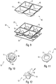
- the four pot-like reflectors 20 are, however, preferably isolated to the one in the Figures 6 and 7 2x2 grid 30 shown, since otherwise a correspondingly coordinated positioning of the individual reflectors 20 would be very expensive and laborious.
- the individual reflectors 20 of the grid 30 are each designed approximately like a truncated pyramid and each have a square light exit opening 21 and a circular bottom opening 22 opposite this.
- a special feature here is that the light exit openings 21 of the individual reflectors 20 do not have a square or rectangular shape, but instead represent an irregular rectangle, so that a distorted truncated cone shape also results for the reflector 20.
- the four light exit openings 21 of the 2 ⁇ 2 reflector grid 30 form a square. This is primarily a measure that gives the luminaire 100 an attractive and interesting appearance, since the light output for illuminating a section of road, for example, is primarily carried out by the lenses 10, which are described in more detail below.
- the reflector grids 30 in the present inventive solution represent only a secondary element for the light output of the luminaire 100.
- the light output is primarily determined by the lenses 10 individually assigned to the light sources.
- the shape of the lenses can in particular Figures 10-12 are removed, which are so-called TIR (total internal reflection) lenses, which initially have a collimator 11 facing the light source.
- this collimator 11 is designed to be rotationally symmetrical in the form of a truncated cone and has an approximately circular recess 12 on its light entry side. The positioning takes place here in such a way that the LED protrudes into this recess 12 and accordingly all of the light from the LED falls into the collimator 11.
- On the lateral surface of the collimator 11 then takes place in a known manner total internal reflection of the light, so that it is initially aligned essentially parallel.
- TIR lenses with a collimator facing the light source are already known.
- the light exit area 15 of the lens adjoining the collimator 11 then has a Fresnel-like structure 16, with the aid of which the light is emitted asymmetrically in a preferred direction.
- the light exit area 15 is connected to the collimator 11 via a disk-like intermediate area 14 which, however, does not have any significant influence on the light output, but primarily serves to completely fill the bottom opening 22 of the associated pot-like reflector 20 when the optical system is installed.
- the reflectors 20 are then arranged at a distance from the circuit board 50 and the light sources, this distance being bridged by the collimator 11 of the respective lens 10.
- the orientation of the lens 10 and thus the preferred direction in which the light is primarily emitted can also be seen from an arrow-like marking 14a formed on the disk-like intermediate area 14, so that the direction in which the light is emitted can be seen immediately.
- the light output of the lens 10 via the Fresnel structure 16 is preferably such that it is no longer or only insignificantly influenced by the reflector 20 surrounding the lens 10.
- the four lenses 10 of an individual lamp assembly 50 are each aligned identically so that a lamp assembly 50 emits light uniformly in a certain preferred direction.
- the in the Figures 1 and 2 The lamp assemblies 50 shown in the luminaire 100 then differ, however, with regard to the orientation of the associated lenses 10, so that each lamp assembly 50 emits light in a somewhat different angular range. A superimposition of these eight directions of light emission of the lamp assemblies 50 then leads overall to the longitudinally stretched and thus asymmetrical light output, as is striven for street lighting, as already mentioned.
- the overall resulting configuration of a lamp assembly 50 can then, for example, be shown in FIG Figure 4 can be removed.
- the light from each LED is first coupled into the collimator 11 of the associated lens 10 and then emitted via the Fresnel-like light output region 15 of the lens 10. While the collimator 11 is still arranged below or outside the pot-like reflectors 20, the light decoupling area 15 protrudes into the reflector space.
- the lenses 10 are first placed on the LEDs and then the reflector grid 30 is attached in the next assembly step.
- a special feature of the lenses 10 used is that the light is primarily emitted as desired in the preferred direction defined by the Fresnel structure 16, but at least a small additional portion of the light is targeted laterally or over the circumference of the light exit area 15 is emitted in such a way that it falls on the walls of the pot-like reflector 20.
- Additional decoupling surfaces or structures 17 are responsible for this effect Figure 13 are shown and are responsible for the fact that a small proportion of the light is also emitted in other directions, in particular also in the opposite direction to the preferred light emission direction.
- the (surface) proportion of these coupling-out surfaces 17 is relatively small, since only a very small proportion of the light is intended to be used to brighten the surrounding reflector walls.
- this effect would also be through a corresponding roughening or achievable by adding scattering particles into the lens material, since such scattering counteracts the overall effect of the Fresnel structure 16, the shape shown with the aid of the additional light outcoupling surfaces or light outcoupling structures 17 is to be preferred.
- the lateral decoupling of the second light component should take place over the entire circumference of the light exit area so that the entire reflector walls are actually completely illuminated.
- Each lens 10 thus ensures that a first - preferably large - portion of the light is emitted in the preferred preferred direction and a second - preferably small - portion falls on the walls of the pot reflector 20 over the entire circumference, if possible.
- the light is then scattered as diffuse as possible, which has the effect that when the lamp 100 is switched on, the reflector walls appear to be illuminated even at very flat viewing angles. I.e., also for people who are outside the actually illuminated area, i.e. are located in the area directly illuminated by the lenses 10, the reflector walls appear brighter and it can accordingly be recognized without a doubt whether the lamp is activated or not.
- This also gives the eye the opportunity at an early stage to adapt to the brightness transition when approaching the illuminated area, so that no more severe or disruptive glare occurs during the transition between an area not illuminated by the lenses and an illuminated area.
- the walls of the reflector are designed to be diffusely scattering. That is, in a first variant, which, however, is not the subject of the claims, it would be conceivable that the reflector grid is formed from a material which causes diffuse scattering, or the reflector surfaces could be provided with a diffusely scattering coating.
- the diffuse scattering of the second light component is carried out by an additional reflector insert that is inserted into the Figures 8 and 9 can be seen and is provided with the reference numeral 40.
- the insert 40 is similar to the reflector grid 30 in terms of its design and shape, so it again has four pot-like, frustoconical sections 45, each of which forms a light exit opening 46 and, opposite this, a circular entrance opening 47. Also with regard to the asymmetrical design of the openings 46, the insert 40 resembles the reflector grid 30.
- the dimensions of the insert 40 are now selected, however, in such a way that the outer contour of the Insert 40 corresponds to the inner contour of the reflector grid 30, so that the insert 40 can be inserted into the reflector grid 30 in a form-fitting manner from the top.
- the insert 40 is also made in one piece, the use of individual inserts also being conceivable here in the case of using individual reflector pots.
- This reflector insert 40 now consists of a transparent material, for example PMMA or PC, which is additionally provided with scattering particles so that the insert 40 as a whole can bring about the above-mentioned, desired scattering of the second light component.
- the insert 40 is made of a transparent material, the light is scattered not only on its surface, but also on the scattering particles distributed within the material of the insert 40 and possibly also on the surface of the reflector pot below, so that an optical A very attractive depth effect is achieved and, in particular, the impression is given that the insert 40 as a whole glows slightly when the lamp 100 is activated.
- the insert 40 preferably has an essentially constant wall thickness and is used when assembling the structural unit 50 - as in FIG Figure 9 recognizable - inserted into the reflector grid 30 from the top in the final assembly step.
- FIG 14 Another exemplary embodiment of a lamp 200 according to the invention is shown, which basically corresponds to the first lamp 100 in terms of its structure.
- a first module 210 which contains the electronic components
- a second module 220 which contains the lighting means, wherein the two modules 210, 220 can be coupled in such a way that the lighting means module 220 can be pivoted .
- one difference is first of all that the number of light sources in the illuminant module 220 is lower and only here 16 light sources are used, which are distributed over four light source assemblies.
- the basic structure of the lamp assemblies is again identical to that of the lamp according to FIGS Figures 1 and 2 , although no asymmetrical light distribution is sought, but instead the light should be emitted in a concentrated manner on a certain area.
- the lamp according to Figure 14 the lamp assemblies have differently designed lenses. In particular, lenses are used here, as they are in the Figures 15 and 16 are shown.
- These lenses 60 in turn have a frustoconical collimator section 61 which has a recess 62 facing the light source, the bottom and lateral surface of which forms the light entry surface of the lens.
- a frustoconical collimator section 61 which has a recess 62 facing the light source, the bottom and lateral surface of which forms the light entry surface of the lens.
- no Fresnel-like light emission area 15 is now required through which the light is emitted asymmetrically.
- the light exit region 65 of the lens 60 becomes the Figures 15 and 16 formed by a flat surface over which the light bundled by the collimator 61 is emitted.
- this has the consequence that the light output takes place parallel to the axis of rotation of the collimator 61, in which case the primary light output of the lens 60 is not or only very slightly influenced by the reflector.
- a plate-shaped holding part 67 is now provided, which enables the lens 60 to be positioned in a defined manner on the carrier element of the illuminant assembly.
- the collimator area 61 of the lens 60 with the associated light exit surface ends in the area of the bottom opening 22 of the associated pot reflector 20.
- the light output is primarily determined by the lens 60 itself, and less by the reflector 20.
- scattered light can again occur which is used to brighten the circumferential reflector walls of the pot-like reflector 20.
- a corresponding reflector insert 40 is therefore additionally provided within the reflector grid 30 according to the invention. Either the scattered light which is not completely suppressed anyway and which is emitted by the lens 60 can be used. It would also be possible in a targeted manner, for example by introducing scattering
- the concept according to the invention therefore allows light to be emitted extremely effectively into a desired area, but despite everything to avoid the disadvantages that have so far resulted from strong light control.
- the use of the optical system according to the invention is of course not limited to lights for outdoor use, but can be used with all types of lights.
Description
Die vorliegende Erfindung betrifft ein optisches System gemäß Anspruch 1.The present invention relates to an optical system according to claim 1.
Ferner betrifft die vorliegende Erfindung eine Leuchte, bei der ein entsprechendes optisches System zum Einsatz kommt, wobei es sich bei der Leuchte insbesondere um eine Leuchte handeln kann, die im Außenbereich zur Anwendung kommt.Furthermore, the present invention relates to a lamp in which a corresponding optical system is used, wherein the lamp can in particular be a lamp that is used outdoors.
Leuchten, mit deren Hilfe bestimmte Bereiche oder Objekte beleuchtet werden sollen, müssen zwangsläufig Mittel aufweisen, mit deren Hilfe das von den Leuchtmitteln erzeugte Licht gezielt in den zu beleuchtenden Bereich abgegeben wird. Es handelt sich hierbei in der Regel um zu den Leuchtmitteln zusätzliche optische Elemente, welche durch Reflexion und/oder Brechung des Lichts dieses derart beeinflussen, dass dieses entsprechend der Beleuchtungssituation in gewünschter Weise ausgerichtet wird.Luminaires, with the help of which certain areas or objects are to be illuminated, must inevitably have means with the aid of which the light generated by the lighting means is specifically emitted into the area to be illuminated. As a rule, these are optical elements that are additional to the lighting means, which influence the light through reflection and / or refraction in such a way that it is aligned in the desired manner according to the lighting situation.
Eine Möglichkeit, die Lichtabgabe in der gewünschten Weise zu beeinflussen, sind die erwähnten Reflektoren. Hierbei ist oftmals vorgesehen, dass nicht ein einziger großer Reflektor zum Einsatz kommt, sondern stattdessen mehrere topfartige Reflektoren matrixartig zu einem so genannten Raster zusammengefügt sind, über welches dann das Licht der Leuchtmittel abgegeben wird. Während früher größere Leuchtmittel in Form von länglichen Leuchtstofflampen oder dergleichen zum Einsatz kamen, werden nunmehr in der Regel LEDs verwendet, wobei in diesem Fall dann üblicherweise jedem einzelnen Reflektortopf ein LED-Leuchtmittel zugeordnet ist. Es kann sich bei den Leuchtmitteln jeweils um einzelne LEDs oder auch um Cluster bestehend beispielsweise aus mehreren verschiedenfarbigen LEDs handeln, die dann letztendlich ein Mischlicht in der gewünschten Farbe oder Farbtemperatur abgeben.One possibility of influencing the light output in the desired way are the reflectors mentioned. Here it is often provided that not a single large reflector is used, but instead several pot-like reflectors are joined together like a matrix to form a so-called grid, via which the light from the illuminants is then emitted. While larger illuminants in the form of elongated fluorescent lamps or the like were used in the past, LEDs are now generally used, in which case an LED illuminant is then usually assigned to each individual reflector pot. The lighting means can be individual LEDs or clusters consisting, for example, of several different colored LEDs, which then ultimately emit a mixed light in the desired color or color temperature.
Die Gestaltung des Reflektors ist dann derart, dass aufgrund der Form der Reflektorwand und der entsprechenden Positionierung der Lichtquelle gegenüber dem Reflektor alle Lichtstrahlen derart beeinflusst werden, dass sie den Reflektor nur innerhalb eines bestimmten Winkelbereichs verlassen können, wobei der Winkelbereich derart gewählt ist, dass die Lichtabgabe in die gewünschte Richtung hin erfolgt. Außerhalb dieses in erster Linie durch die Gestaltung des Reflektors definierten Bereichs hingegen erfolgt dann nahezu keine Lichtabgabe, sodass auf diese Weise sehr einfach und effektiv das Licht beeinflusst werden kann. Reflektorraster dieser Art kommen deshalb sehr häufig und in unterschiedlichen Anwendungsgebieten zum Einsatz, um beispielsweise eine sog. blendfreie Beleuchtung zu realisieren oder störende Reflexionen an Bildschirmoberflächen oder dergleichen zu vermeiden.The design of the reflector is then such that due to the shape of the reflector wall and the corresponding positioning of the light source relative to the reflector, all light rays are influenced in such a way that they can only leave the reflector within a certain angular range, the angular range being selected such that the Light emission takes place in the desired direction. Outside of this area, which is primarily defined by the design of the reflector, on the other hand, almost no light is emitted, so that the light can be influenced very easily and effectively in this way. Reflector grids of this type are therefore used very frequently and in different areas of application, for example to achieve so-called glare-free lighting or to avoid disruptive reflections on screen surfaces or the like.
Die vollständige Beschränkung der Lichtabgabe auf den durch den Reflektor vorgegebenen Winkelbereich hat allerdings auf der anderen Seite zur Folge, dass die Leuchte bzw. der eingeschaltete Zustand der Leuchte durch einen Beobachter nur dann erkennbar ist, wenn er sich in dem Raumwinkelbereich befindet, in den die durch den Reflektor vorgegebene Lichtabgabe erfolgt. Befindet sich der Beobachter hingegen außerhalb dieses Winkelbereichs, so erscheint die Leuchte zunächst aus seiner Sicht dunkel.The complete restriction of the light output to the angular range given by the reflector has, on the other hand, the consequence that the lamp or the switched-on state of the lamp can only be recognized by an observer if he is in the solid angle range in which the light output predetermined by the reflector takes place. If, on the other hand, the observer is outside this angular range, the light initially appears dark from his point of view.
Dies wiederum bedeutet, dass durch das Auge des Beobachters beim Übergang von dem nicht beleuchteten Bereich in den beleuchteten Bereich ein starker Helligkeitsanstieg stattfindet, an den sich das Auge innerhalb kürzester Zeit gewöhnen muss. Dies wird häufig als unangenehm empfunden, weshalb oftmals versucht wird, mit Hilfe zusätzlicher Beleuchtungseffekte einerseits dem Beobachter den eingeschalteten Zustand der Leuchte zu signalisieren und andererseits dem Auge des Beobachters zu ermöglichen, sich bereits vorab zumindest zu einem gewissen Grad an die erhöhte Helligkeit, die in dem beleuchteten Bereich vorliegt, zu adaptieren. Bei diesen Maßnahmen handelt es sich oftmals um eine indirekte oder sekundäre Lichtabgabe, die mit Hilfe von zusätzlichen Lichtquellen erzielt wird, welche beispielsweise Licht auf die Decke eines Raums richten, in dem sich die Leuchte befindet, oder seitlich Licht diffus abgeben.This in turn means that the eye of the observer at the transition from the non-illuminated area to the illuminated area causes a strong increase in brightness to which the eye has to get used to within a very short time. This is often perceived as unpleasant, which is why attempts are often made to signal the switched-on state of the lamp to the observer with the help of additional lighting effects on the one hand and to the eye of the on the other hand To enable the observer to adapt in advance, at least to a certain extent, to the increased brightness that is present in the illuminated area. These measures often involve indirect or secondary light output, which is achieved with the help of additional light sources which, for example, direct light onto the ceiling of a room in which the luminaire is located, or give off diffuse light from the side.
Derartige Maßnahmen zur sekundären Lichtabgabe sind jedoch mit einem zusätzlichen Aufwand verbunden und bei Leuchten im Außenbereich eher unüblich bzw. nicht realisierbar. Auch hier stellt sich allerdings oftmals das Problem, dass abrupte Helligkeitsanstiege beim Übergang von einem nicht beleuchteten Bereich in einen beleuchteten Bereich vermieden werden sollen.Such measures for secondary light emission are, however, associated with additional expenditure and are rather unusual or not feasible in the case of luminaires in outdoor areas. Here too, however, the problem often arises that abrupt increases in brightness should be avoided during the transition from a non-illuminated area to an illuminated area.
Das oben geschilderte Problem liegt im Übrigen nicht nur beim Einsatz von Reflektorrastern oder topfartigen Einzelreflektoren vor, sondern kann sich auch bei anderen Arten von Optiken ergeben. Beispielsweise kommen zur Beeinflussung des Lichts von LEDs sehr häufig so genannte TIR-Linsen zum Einsatz, welche äußerst effizient das ursprünglich von der LED in einem sehr weiten Winkelbereich abgegebene Licht bündeln, also auf einen bestimmten Winkelbereich einschränken. Auch in diesem Fall treten am Übergang zwischen dem nicht beleuchteten Bereich und dem beleuchteten Bereich starke Helligkeitsunterschiede auf, die als unangenehm empfunden werden.The problem described above does not only exist when using reflector grids or cup-like individual reflectors, but can also arise with other types of optics. For example, so-called TIR lenses are very often used to influence the light from LEDs, which extremely efficiently bundle the light originally emitted by the LED in a very wide angular range, i.e. restrict it to a specific angular range. In this case too, strong differences in brightness occur at the transition between the non-illuminated area and the illuminated area, which are perceived as unpleasant.
Der vorliegenden Erfindung liegt deshalb die Aufgabenstellung zugrunde, neuartige Möglichkeiten zur Beeinflussung der Lichtabgabe einer Lichtquelle zur Verfügung zu stellen, welche es einerseits gestatten, sehr effizient das Licht in einen gewünschten Bereich abzugeben, andererseits jedoch die oben beschriebenen Probleme vermeiden.The present invention is therefore based on the object of providing novel possibilities for influencing the light output of a light source, which on the one hand allow the light to be emitted very efficiently in a desired area, but on the other hand avoid the problems described above.
Die Aufgabe wird durch ein optisches System, welches die Merkmale des Anspruchs 1 aufweist, gelöst. Vorteilhafte Weiterbildungen sind Gegenstand der abhängigen Ansprüche.The object is achieved by an optical system which has the features of claim 1. Advantageous further developments are the subject of the dependent claims.
Die erfindungsgemäße Lösung beruht auf dem Gedanken, die Lichtabgabe einer Lichtquelle, beispielsweise einer LED, einerseits mit Hilfe eines topfartigen Reflektors und Einsatzes und andererseits mit Hilfe einer Linse zu beeinflussen. Dabei ist vorgesehen, dass die Linse derart ausgeführt ist, dass ein erster Anteil des Lichts im Wesentlichen unabhängig von dem Reflektor in eine durch die Linse definierte Vorzugsrichtung abgestrahlt wird. Ferner ist die Linse allerdings zusätzlich dazu ausgebildet, einen zweiten Anteil des Lichts seitlich derart abzugeben, dass dieser Anteil auf die Innenwand des Reflektors fällt. Diese Reflektorwand ist insbesondere diffus reflektierend ausgestaltet, sodass sie durch den zweiten Anteil des Lichts aus unterschiedlichsten Blickrichtungen leicht aufgehellt erscheint.The solution according to the invention is based on the idea of influencing the light output of a light source, for example an LED, on the one hand with the aid of a pot-like reflector and insert and on the other hand with the aid of a lens. It is provided that the lens is designed such that a first portion of the light is radiated essentially independently of the reflector in a preferred direction defined by the lens. Furthermore, the lens is also designed to emit a second portion of the light laterally in such a way that it Part falls on the inner wall of the reflector. This reflector wall is designed in particular to be diffusely reflective, so that it appears slightly brightened by the second portion of the light from the most varied of viewing directions.
Selbst unter flachen Beobachtungswinkeln, unter denen ein Blenden für einen Beobachter ausgeschlossen werden soll und in die dementsprechend der primäre Anteil des Lichts mit Hilfe der Linse nicht abgegeben wird, erscheint also die Innenwand des Reflektors leicht erhellt und kann durch einen Beobachter erkannt werden. Damit ist für den Beobachter noch vor Erreichen des durch die Linse direkt beleuchteten Bereichs ohne weiteres erkennbar, dass die Leuchte eingeschaltet ist, und Helligkeitsunterschiede beim Übergang in den durch den ersten Anteil direkt beleuchteten Bereich werden dementsprechend nicht mehr als störend wahrgenommen.Even at flat viewing angles, at which glare should be excluded for an observer and into which the primary portion of the light is accordingly not emitted with the help of the lens, the inner wall of the reflector appears slightly illuminated and can be recognized by an observer. This means that the observer can easily see before reaching the area directly illuminated by the lens that the lamp is switched on, and differences in brightness during the transition into the area directly illuminated by the first component are accordingly no longer perceived as disturbing.
Gemäß der vorliegenden Erfindung wird also ein optisches System zum Beeinflussen der Lichtabgabe einer Lichtquelle vorgeschlagen, welches einen topfartigen Reflektor aufweist, der eine Lichtaustrittsöffnung aufweist, sowie eine Linse, die dazu ausgebildet ist, einen ersten Anteil des Lichts über die Lichtaustrittsöffnung des Reflektors in eine durch die Linse definierte Vorzugsrichtung abzustrahlen, wobei ferner die Linse dazu ausgebildet ist, einen zweiten Anteil des Lichts seitlich derart abzugeben, dass dieser Anteil auf die Reflektorinnenwand fällt.According to the present invention, an optical system for influencing the light output of a light source is proposed, which has a pot-like reflector which has a light exit opening, and a lens which is designed to pass a first portion of the light through the light exit opening of the reflector to emit the lens in a defined preferred direction, the lens also being designed to emit a second portion of the light laterally in such a way that this portion falls on the reflector inner wall.
Die Erfindung ist dadurch gekennzeichnet, dass zusätzlich ein in den Reflektor einsetzbarer, ebenfalls topfartiger Einsatz vorgesehen ist, der aus einem transparenten und diffus streuenden Material besteht.The invention is characterized in that a cup-like insert that can be inserted into the reflector is additionally provided and consists of a transparent and diffusely scattering material.
Dieser Einsatz, der mit seiner Außenkontur der Innenkontur des Reflektors entspricht, liegt also an den Innenwänden des Reflektors an, streut allerdings bereits in unterschiedlichster Weise den zweiten Anteil des Lichts, der auf ihn fällt, wobei die Streupartikel einerseits und das transparente Material des Einsatzes andererseits einen optischen Tiefeneffekt hervorrufen, der den Einsatz insgesamt leicht glühend erscheinen lässt. Dies verleiht der erfindungsgemäßen Leuchte im eingeschalteten Zustand ein besonders ansprechendes Aussehen.This insert, the outer contour of which corresponds to the inner contour of the reflector, rests against the inner walls of the reflector, but already scatters the second portion of the light that falls on it in different ways, with the scattering particles on the one hand and the transparent material of the insert on the other create an optical depth effect that makes the insert appear slightly glowing overall. This gives the lamp according to the invention a particularly attractive appearance when switched on.
Dieser erfindungsgemäße sogenannte Glow-Reflektoreinsatz, der vorzugsweise eine konstante Wandstärke aufweist, kann hierbei beispielsweise aus PMMA oder PC gebildet sein.This so-called glow reflector insert according to the invention, which preferably has a constant wall thickness, can be formed from PMMA or PC, for example.
Bei der erfindungsgemäßen Lösung erfüllt der topfartige Reflektor also im Vergleich zu bisherigen Leuchtenrastern weniger die Aufgabe, die Lichtabgabe auf einen bestimmten Winkelbereich einzuschränken, sondern er dient vielmehr nunmehr dazu, einen geringen Lichtanteil diffus in unterschiedlichste Richtungen abzugeben, um den Einschaltzustand der Leuchte erkennbar zu gestalten. Die eigentliche Lichtlenkung hingegen wird durch die Linse vorgenommen, sodass hier also ein völlig neuartiges Zusammenwirken der beiden optischen Elemente Reflektor und Linse vorliegt.In the solution according to the invention, the pot-like reflector fulfills the task of restricting the light output to a certain angular range compared to previous luminaire grids, but rather it now serves to diffuse a small amount of light in different directions in order to make the switched-on state of the lamp recognizable . The actual light control, on the other hand, is carried out by the lens, so that the two optical elements reflector and lens interact in a completely new way.
Die Linse kann hierbei in klassischer Weise eine so genannte TIR-Linse sein. Sie weist in diesem Fall dann zunächst einen der Lichtquelle zugewandten, etwa kegelstumpfartigen so genannten Kollimator auf. Dieser kann eine der Lichtquelle zugewandte Ausnehmung aufweisen, deren Mantel- und Bodenfläche eine Lichteintrittsfläche der Linse bildet, wobei in bekannter Weise die LED dann im Bereich dieser Ausnehmung positioniert wird.The lens can be a so-called TIR lens in the classic way. In this case, it then initially has a so-called collimator, which is approximately frustoconical and faces the light source. This can have a recess facing the light source, the jacket and bottom surfaces of which form a light entry surface of the lens, the LED then being positioned in the area of this recess in a known manner.
Die Linse kann dann gemäß einem ersten Ausführungsbeispiel eine im Wesentlichen plane Lichtaustrittsfläche aufweisen. In diesem Fall wird das Licht dann vorzugsweise in einer Richtung, die im Wesentlichen parallel zur Senkrechten bezüglich der Ebene der Lichtaustrittsöffnung des Reflektors liegt, abgegeben. Eine Aufhellung der Reflektorinnenwand durch den zweiten Anteil des Lichts kann dann beispielsweise dadurch erzielt werden, dass Streulicht genutzt wird, welches durch die Linse abgegeben wird. Dieser Effekt kann darüber hinaus auch gezielt dadurch verstärkt werden, dass beispielsweise Randbereiche der Lichtaustrittsfläche der Linse gezielt mit einer entsprechenden Streustruktur versehen werden.According to a first exemplary embodiment, the lens can then have an essentially planar light exit surface. In this case, the light is then preferably emitted in a direction which is essentially parallel to the perpendicular with respect to the plane of the light exit opening of the reflector. The inner wall of the reflector can then be brightened by the second portion of the light, for example, by using scattered light which is emitted by the lens. In addition, this effect can also be intensified in a targeted manner in that, for example, edge areas of the light exit surface of the lens are specifically provided with a corresponding scatter structure.
Alternativ zu dieser Ausführungsform einer Linse kann allerdings auch vorgesehen sein, dass die Abgabe des ersten Lichtanteils in einer Richtung erfolgt, die gegenüber einer senkrecht auf der Ebene der Lichtaustrittsöffnung des Reflektors stehenden Achse geneigt ist. Dies kann insbesondere dann gewünscht sein, wenn z.B. der Reflektor senkrecht nach unten ausgerichtet ist, mit Hilfe der Leuchte allerdings beispielsweise eine asymmetrische Lichtabgabe erzielt werden soll, wie sie bei Leuchten zur Straßenbeleuchtung oder dergleichen gewünscht ist. In diesem Fall müssen dann also Linsen zum Einsatz kommen, die eine asymmetrische Lichtabgabe bewirken, was beispielsweise dadurch erfolgen kann, dass der Lichtaustrittsbereich der Linse eine so genannte Fresnel-Struktur aufweist. Um auch in diesem Fall die erfindungsgemäße Aufhellung der Reflektorinnenwand mit Hilfe des zweiten Lichtanteils erzielen zu können, kann nunmehr vorgesehen sein, dass am Umfang der Fresnel-Struktur eine Streu- oder Auskoppelstruktur ausgebildet ist, über die der zweite Lichtanteil abgegeben wird. Die Linse ist in diesem Fall vorzugsweise zumindest mit ihrem Lichtaustrittsbereich bzw. der Fresnel-Struktur innerhalb des Reflektors angeordnet.As an alternative to this embodiment of a lens, however, it can also be provided that the first light component is emitted in a direction which is inclined with respect to an axis perpendicular to the plane of the light exit opening of the reflector. This can be particularly desirable when, for example, the reflector is oriented vertically downwards, but with the aid of the lamp, for example, an asymmetrical light output is to be achieved, as is desired in lamps for street lighting or the like. In this case, lenses must then be used which bring about an asymmetrical light emission, which can take place, for example, in that the light exit region of the lens has a so-called Fresnel structure. In order to be able to achieve the inventive brightening of the reflector inner wall with the aid of the second light component in this case, it can now be provided that a scattering or decoupling structure is formed on the circumference of the Fresnel structure, via which the second light component is emitted. In this case, the lens is preferably arranged at least with its light exit area or the Fresnel structure within the reflector.
Der erfindungsgemäße lichttechnische Effekt, dass nämlich mit Hilfe der illuminierten Reflektorinnenwand aus unterschiedlichsten Blickrichtungen der Einschaltzustand der Leuchte erkannt werden kann, kommt besonders dann gut zum Tragen, wenn der Reflektor diffus streuend ausgebildet ist.The lighting effect according to the invention, namely that with the aid of the illuminated reflector inner wall, the switched-on state of the lamp can be recognized from a wide variety of viewing directions, is particularly effective when the reflector is designed to be diffusely scattering.
Die Verwendung des zusätzlichen Einsatzes ist nicht zwingend in Kombination mit der zuvor beschriebenen Linse erforderlich. Vielmehr könnte ein derartiger Einsatz auch bei anderen optischen Systemen zum Einsatz kommen (nicht beansprucht). 3emäß einem bevorzugten Ausführungsbeispiel ist hierbei das optische System derart ausgeführt, dass dieses mehrere Reflektoren aufweist, welche matrixartig angeordnet sind und gemeinsam ein entsprechendes Raster bilden. Die Reflektoren können hierbei zumindest teilweise einstückig miteinander verbunden sein. Kommen dann die oben erwähnten zusätzlichen Einsätze aus dem transparenten und diffus streuenden Material zum Einsatz, so sind auch diese vorzugsweise einstückig ausgeführt, sodass sie in entsprechender Weise von der Lichtaustrittsseite her an das Raster angesetzt und beispielsweise mit diesem verrastet werden können.The use of the additional insert is not absolutely necessary in combination with the lens described above. Rather, such an application could also be used in other optical systems (not claimed). According to a preferred exemplary embodiment, the optical system is designed in such a way that it has a plurality of reflectors which are arranged like a matrix and together form a corresponding grid. The reflectors can be at least partially connected to one another in one piece. If the above-mentioned additional inserts made of the transparent and diffusely scattering material are used, then these are also preferably made in one piece so that they can be attached to the grid in a corresponding manner from the light exit side and, for example, locked to it.
Wie bereits erwähnt stellt ein bevorzugtes Anwendungsbeispiel der Erfindung eine Leuchte im Außenbereich dar. Es kann sich hierbei sowohl um eine Leuchte handeln, die gezielt Licht gebündelt in einen gewünschten Bereich abgibt um beispielsweise ein in diesem Bereich befindliches Objekt oder dergleichen zu beleuchten. In gleicher Weise kann allerdings auch eine Leuchte realisiert werden, die beispielsweise zur Ausleuchtung einer Straße oder eines Gehwegs genutzt wird und dementsprechend insgesamt eine asymmetrische Lichtabgabe bewirkt, welche eine Beleuchtung eines längeren Straßenabschnitts ermöglicht.As already mentioned, a preferred application example of the invention is a light in the outdoor area. This can be a light, which emits focused light in a targeted manner in a desired area, for example to illuminate an object or the like located in this area. In the same way, however, a luminaire can also be implemented that is used, for example, to illuminate a street or a sidewalk and accordingly overall effects an asymmetrical light output, which enables a longer street section to be illuminated.
Nachfolgend soll die Erfindung anhand der beiliegenden Zeichnung näher erläutert werden. Es zeigen:
- Figuren 1 und 2
- Ansichten eines ersten Ausführungsbeispiels einer Leuchte, bei der das erfindungsgemäße optische System zum Einsatz kommen kann;
- Figuren 3 bis 5
- Ansichten einer einzelnen, für die Lichterzeugung verantwortlichen Leuchtmittel-Baugruppe der Leuchte;
- Figuren 6 und 7
- Ansichten eines Reflektorrasters, welches Bestandteil der in den
Figuren 3 bis 5 gezeigten Leuchtmittel-Baugruppe ist; - Figur 8
- eine seitliche Ansicht eines erfindungsgemäßen Glow-Einsatzes für das Reflektorraster;
- Figur 9
- den Vorgang des Zusammenfügens der Leuchtmittel-Baugruppe;
Figuren 10bis 12- Ansichten einer erfindungsgemäßen Linse, mit deren Hilfe einerseits Licht in eine Vorzugsrichtung abgegeben wird und andererseits die Reflektorwände beleuchtet werden;
- Figur 13
- eine vergrößerte Ansicht der
Linse der Figuren 10 ;bis 12 Figur 14- ein zweites Ausführungsbeispiel einer Leuchte, bei der das erfindungsgemäße optische System zum Einsatz kommen kann und
Figuren 15 und 16- Ansichten einer bei dieser zweiten Leuchte zum Einsatz kommenden alternativen Linse.
- Figures 1 and 2
- Views of a first exemplary embodiment of a lamp in which the optical system according to the invention can be used;
- Figures 3 to 5
- Views of an individual lamp assembly of the luminaire responsible for generating light;
- Figures 6 and 7
- Views of a reflector grid, which is part of the
Figures 3 to 5 lamp assembly shown is; - Figure 8
- a side view of a glow insert according to the invention for the reflector grid;
- Figure 9
- the process of assembling the lamp assembly;
- Figures 10 to 12
- Views of a lens according to the invention, with the aid of which light is emitted in a preferred direction on the one hand and the reflector walls are illuminated on the other hand;
- Figure 13
- an enlarged view of the lens of FIG
Figures 10 to 12 ; - Figure 14
- a second embodiment of a lamp in which the optical system according to the invention can be used and
- Figures 15 and 16
- Views of an alternative lens used in this second lamp.
Die
Grundsätzlich ist die Leuchte 100 zweiteilig aufgebaut mit einem etwa quaderförmigen ersten Modul 110 sowie einem zweiten Modul 120, dem sog. Leuchtmittelmodul, welches ebenfalls quaderförmig ausgebildet und an dem ersten Modul 110 befestigt ist. Das erste Modul 110 beinhaltet hierbei einen Großteil der elektronischen Komponenten der Leuchte 100, insbesondere die erforderlichen Mittel zum Umsetzen der allgemeinen Versorgungsspannung in eine zum Betrieb der Leuchtmittel geeignete Betriebsspannung. Es kann sich hierbei insb. um einen entsprechend gestalteten LED-Konverter handeln.The
Die Befestigung der Leuchte 100 an einem geeigneten Träger erfolgt über einen Anschlussbereich 115, der an einer Rückwand 111 des ersten Moduls 110 ausgebildet ist. Über diesen Anschlussbereich 115 erfolgt auch die Verbindung an externe Stromversorgungsleitungen, wobei gemäß einer bevorzugten Variante auch vorgesehen sein kann, dass der Anschlussbereich 115 eine Rotationsachse R definiert, um die - zumindest in einem gewissen Winkelbereich - das erste Modul 110 und damit die Leuchte 100 insgesamt verdreht bzw. verschwenkt werden kann.The
Das Leuchtmittelmodul 120 ist entsprechend der Darstellung ebenfalls quaderförmig ausgebildet und weist in Längsrichtung gesehen vergleichbare Abmessungen wie das erste Modul 110 auf, ist allerdings aus ästhetischen Gründen leicht versetzt zu diesem angeordnet. Die Befestigung des Leuchtmittelmoduls 120 an dem ersten Modul 110 kann hierbei starr sein. Alternativ hierzu wäre es allerdings auch denkbar, die Anbindung derart zu gestalten, dass entsprechend dem angedeuteten Pfeil das Leuchtmittelmodul 120 um eine Achse, die parallel zur Längsrichtung L verläuft, verschwenkt werden kann. Auch hier kann die Anbindung derart ausgeführt sein, dass das Verschwenken des Leuchtmittelmoduls 120 auf einem bestimmten Winkelbereich eingeschränkt wird. Im Falle der Verwendung als Leuchte zur Straßenbeleuchtung kann dann bspw. durch das Verschwenken die Lichtabgabe an den Abstand zwischen der zu beleuchtenden Fahrbahn und dem Träger, an dem die Leuchte 100 befestigt ist, angepasst werden.The
Nachfolgend soll in erster Linie die Ausgestaltung des Leuchtmittelmoduls 120 erläutert werden, da dieses die erfindungsgemäßen optischen Komponenten beinhaltet.The design of the
Wie in
Die in
Jede Baugruppe weist dabei wie in den
Die Leiterplatte 55 dient darüber hinaus auch der Halterung der weiteren optischen Komponenten, die für die Beeinflussung der Lichtabgabe verantwortlich sind. Es handelt sich hierbei zunächst um Linsen 10, sowie um topfartig ausgebildete Reflektoren 20. Sowohl die Linsen 10 als auch die Reflektoren 20 sind vorzugsweise jeweils miteinander zu einer Baugruppe verbunden, um die Anzahl der Einzelteile beim Zusammenbau der Leuchte 100 möglichst gering zu halten. Insbesondere jedoch die Linsen 10 könnten ggf. auch als Einzelkomponenten vorliegen. Die vier topfartigen Reflektoren 20 sind jedoch bevorzugt zu dem isoliert in den
Die Einzelreflektoren 20 des Rasters 30 sind jeweils etwa pyramidenstumpfartig ausgeführt und weisen jeweils eine viereckige Lichtaustrittsöffnung 21 sowie dieser gegenüberliegend eine kreisförmige Bodenöffnung 22 auf. Eine Besonderheit besteht hierbei darin, dass die Lichtaustrittsöffnungen 21 der einzelnen Reflektoren 20 keine quadratische oder rechteckige Form aufweisen, sondern stattdessen ein unregelmäßiges Viereck darstellen, so dass sich auch eine verzerrte Kegelstumpfform für den Reflektor 20 ergibt. Insgesamt jedoch bilden die vier Lichtaustrittsöffnungen 21 des 2x2-Reflektorrasters 30 ein Quadrat. Es handelt sich hierbei in erster Linie um eine Maßnahme, die der Leuchte 100 ein ansprechendes und interessantes Aussehen verleiht, da die Lichtabgabe zur Beleuchtung bspw. eines Straßenabschnitts in erster Linie durch die nachfolgend noch näher beschriebenen Linsen 10 erfolgt. Dementsprechend wäre es beispielsweise auch möglich, quadratische Lichtaustrittsöffnungen 21 für die Einzelreflektoren 20 zu wählen. Das aus den vier Reflektoren 20 gebildete Reflektorraster 30 wird dann über einen an seiner Unterseite vorgesehenen Rastzapfen 31 (s.
Im Gegensatz zu klassischen Reflektorrastern stellen die Reflektorraster 30 bei der vorliegenden erfindungsgemäßen Lösung allerdings lediglich ein sekundäres Element für die Lichtabgabe der Leuchte 100 dar. Primär wird die Lichtabgabe nämlich durch die jeweils individuell den Lichtquellen zugeordneten Linsen 10 festgelegt. Die Gestalt der Linsen kann dabei insbesondere den
Im vorliegenden Beispiel weist dann der sich an den Kollimator 11 anschließende Lichtaustrittsbereich 15 der Linse eine fresnel-artige Struktur 16 auf, mit deren Hilfe das Licht in eine Vorzugsrichtung asymmetrisch abgestrahlt wird. Der Lichtaustrittsbereich 15 ist dabei mit dem Kollimator 11 über einen scheibenartigen Zwischenbereich 14 verbunden, der allerdings keinen wesentlichen Einfluss auf die Lichtabgabe nimmt, sondern in erster Linie dazu dient, im montierten Zustand des optischen Systems vollständig die Bodenöffnung 22 des zugehörigen topfartigen Reflektors 20 auszufüllen. Wie in
Die fresnel-artige Struktur 16 der Linse 10, die besonders gut in den
Wie anhand die in
Selbstverständlich wäre es auch denkbar, jeweils eine einzelne Linse 10 individuell in eine gewünschte Richtung auszurichten und hierdurch die asymmetrische Lichtabgabe zu erzielen. Die dargestellte Variante, bei der alle Linsen 10 einer Leuchtmittel-Baugruppe 50 die gleiche Orientierung aufweisen, ist allerdings insofern von Vorteil, als sich der Ausfall einer einzelnen LED nicht negativ auf die Gesamtlichtabgabe der Leuchte 100 auswirkt und nicht zu befürchten ist, dass dann Teilbereiche des insgesamt zu beleuchtenden Bereichs nicht mehr beleuchtet werden.Of course, it would also be conceivable to align a
Die sich insgesamt ergebende Ausgestaltung einer Leuchtmittel-Baugruppe 50 kann dann bspw. der Darstellung von
Mit den bislang beschriebenen Maßnahmen kann also effizient ein zu beleuchtender Bereich durch die erfindungsgemäße Leuchte 100 beleuchtet werden. Es ergibt sich allerdings noch das eingangs geschilderte Problem, dass für einen Beobachter, der sich außerhalb des durch die Linsen 10 direkt beleuchteten Bereichs befindet, nicht bzw. nur schwer erkennbar ist, ob die Leuchte 100 überhaupt aktiviert ist oder nicht. Mit Hilfe der nachfolgend beschriebenen zusätzlichen optischen Maßnahmen wird dieses Problem in eleganter Weise gelöst.With the measures described so far, an area to be illuminated can thus be efficiently illuminated by the
Eine Besonderheit der zum Einsatz kommenden Linsen 10 besteht nämlich darin, dass zwar primär das Licht wie gewünscht in der durch den Fresnel-Struktur 16 definierten Vorzugsrichtung abgegeben wird, gezielt jedoch ein zumindest kleiner weiterer Anteil des Lichts seitlich bzw. über den Umfang des Lichtaustrittsbereichs 15 derart abgegeben wird, dass es auf die Wände des topfartigen Reflektors 20 fällt. Verantwortlich für diesen Effekt sind zusätzliche Auskoppelflächen oder -strukturen 17, die in
Jede Linse 10 sorgt also dafür, dass ein erster - vorzugsweise großer - Anteil des Lichts in der gewünschten Vorzugsrichtung abgegeben wird und ein zweiter - vorzugsweise kleiner - Anteil möglichst über den gesamten Umfang hinweg auf die Wände des Topfreflektors 20 fällt. Hier soll dann eine möglichst diffuse Streuung des Lichts erfolgen, die bewirkt, dass im eingeschalteten Zustand der Leuchte 100 auch unter sehr flachen Beobachtungswinkeln die Reflektorwände erhellt erscheinen. D.h., auch für Personen, die sich außerhalb des eigentlich beleuchteten Bereichs, d.h. in dem durch die Linsen 10 direkt beleuchteten Bereich befinden, erscheinen die Reflektorwände heller und es ist dementsprechend zweifelsfrei erkennbar, ob die Leuchte aktiviert ist oder nicht. Hierdurch wird ferner auch dem Auge bereits frühzeitig die Möglichkeit eröffnet, bei einer Annäherung an den beleuchteten Bereich sich an den Helligkeitsübergang anzupassen, sodass dann beim Übergang zwischen einem durch die Linsen nicht beleuchteten Bereich und einem beleuchteten Bereich keine starken bzw. störenden Blendungen mehr auftreten.Each
Dieser lichttechnische Effekt könnte also beispielsweise dadurch erzielt werden, dass neben der speziellen Ausgestaltung der Linse die Wände des Reflektors diffus streuend ausgebildet sind. D.h., in einer ersten Variante, die allerdings nicht Gegenstand der Ansprüche ist, wäre denkbar, dass das Reflektorraster aus einem Material gebildet ist, welches eine diffuse Streuung bewirkt, bzw. die Reflektorflächen könnten mit einer diffus streuenden Beschichtung versehen sind.This photometric effect could therefore be achieved, for example, in that, in addition to the special design of the lens, the walls of the reflector are designed to be diffusely scattering. That is, in a first variant, which, however, is not the subject of the claims, it would be conceivable that the reflector grid is formed from a material which causes diffuse scattering, or the reflector surfaces could be provided with a diffusely scattering coating.
Erfindungsgemäß ist hingegen vorgesehen, dass die diffuse Streuung des zweiten Lichtanteils durch einen zusätzlichen Reflektoreinsatz erfolgt, der in den
Dieser Reflektoreinsatz 40 besteht nunmehr aus einem transparenten Material, beispielsweise PMMA oder PC, das zusätzlich mit streuenden Partikeln versehen ist, sodass der Einsatz 40 insgesamt die oben erwähnte, angestrebte Streuung des zweiten Lichtanteils bewirken kann. Dadurch jedoch, dass der Einsatz 40 aus einem transparenten Material gebildet ist, erfolgt die Lichtstreuung nicht nur an dessen Oberfläche, sondern auch an den innerhalb des Materials des Einsatzes 40 verteilten Streupartikeln sowie ggf. auch an der Oberfläche des darunter liegenden Reflektortopfs, sodass ein optisch sehr ansprechender Tiefeneffekt erzielt wird und insbesondere der Eindruck erweckt wird, dass der Einsatz 40 insgesamt bei aktivierter Leuchte 100 leicht glüht. Der Einsatz 40 weist dabei vorzugsweise im Wesentlichen eine konstante Wandstärke auf und wird beim Zusammenfügen der Baueinheit 50 - wie in
Mit Hilfe dieser Maßnahmen wird also nicht nur das der Erfindung zugrundeliegende Problem gelöst, dass nämlich aus flachen Blickwinkeln heraus der Einschaltzustand der Leuchte nicht erkennbar ist, sondern darüber hinaus wird insbesondere im eingeschalteten Zustand der Leuchte ein besonders ansprechendes Aussehen verliehen.With the help of these measures, not only the problem underlying the invention is solved, namely that the switched-on state of the lamp cannot be seen from flat angles, but also gives the lamp a particularly attractive appearance, especially when the lamp is switched on.
Dabei ist darauf hinzuweisen, dass diese spezielle Kombination von Reflektor und zugehörigem lichtstreuendem transparentem Einsatz nicht zwingend auf die dargestellte Linsenform beschränkt ist, sondern auch bei anderen Primäroptiken zum Einsatz kommen kann.It should be pointed out that this special combination of reflector and associated light-scattering transparent insert is not necessarily restricted to the lens shape shown, but can also be used with other primary optics.
Hierzu ist in
Der grundsätzliche Aufbau der Leuchtmittelbaugruppen ist wiederum identisch zu demjenigen der Leuchte gemäß den
Diese Linsen 60 weisen wiederum einen kegelstumpfartigen Kollimatorabschnitt 61 auf, der eine der Lichtquelle zugewandte Ausnehmung 62 aufweist, deren Boden und Mantelfläche die Lichteintrittsfläche der Linse bildet. Im Gegensatz zu den Linsen 10 der
Im Bodenbereich des Kollimators 61 ist nunmehr ein plattenförmiges Halteteil 67 vorgesehen, welches eine definierte Positionierung der Linse 60 auf dem Trägerelement der Leuchtmittelbaugruppe ermöglicht. Im montierten Zustand der Leuchtmittelbaugruppe 50 endet hierbei der Kollimatorbereich 61 der Linse 60 mit der zugehörigen Lichtaustrittsfläche im Bereich der bodenseitigen Öffnung 22 des zugehörigen Topfreflektors 20.In the bottom area of the
Auch bei dieser Variante wird also die Lichtabgabe primär durch die Linse 60 selbst festgelegt, weniger durch den Reflektor 20. Wiederum kann allerdings Streulicht auftreten, welches dazu genutzt wird, die umlaufenden Reflektorwände des topfartigen Reflektors 20 aufzuhellen. Auch in diesem Fall ist deshalb erfindungsgemäß zusätzlich innerhalb des Reflektorrasters 30 ein entsprechender Reflektoreinsatz 40 vorgesehen. Dabei kann entweder das ohnehin nicht vollständig zu unterdrückende Streulicht, welches durch die Linse 60 abgegeben wird, genutzt werden. Auch wäre es möglich, gezielt bspw. durch das Einbringen von streuendenIn this variant, too, the light output is primarily determined by the
Partikeln oder Strukturen im Randbereich der Lichtaustrittsfläche 65 einen geringfügigen Lichtanteil derart abzustrahlen, dass er die Reflektorwände beleuchtet. D.h., auch bei dieser zweiten dargestellten Leuchte 200 kann der vorteilhafte Effekt erzielt werden, dass eine außerhalb des beleuchteten Bereichs befindliche Person ohne Weiteres den Einschaltzustand der Leuchte 200 erkennen kann.Particles or structures in the edge area of the
Letztendlich gestattet das erfindungsgemäße Konzept also, Licht äußerst effektiv in einen gewünschten Bereich abzugeben, trotz allem jedoch die sich bislang bei einer starken Lichtlenkung ergebenden Nachteile zu vermeiden. Dabei ist selbstverständlich die Anwendung des erfindungsgemäßen optischen Systems nicht auf Leuchten für den Außenbereich beschränkt, sondern kann bei jeglichen Arten von Leuchten vorgenommen werden.Ultimately, the concept according to the invention therefore allows light to be emitted extremely effectively into a desired area, but despite everything to avoid the disadvantages that have so far resulted from strong light control. The use of the optical system according to the invention is of course not limited to lights for outdoor use, but can be used with all types of lights.
Claims (13)
- Optical system for influencing the light emission of a light source, comprising• a pot-shaped reflector (20), which comprises a light exit opening (21),• a lens (10), which is configured to emit a first portion of the light via the light exit opening (21) of the reflector (20) in a preferred direction defined by the lens (10),wherein the lens (10, 60) is further configured to laterally emit a second portion of the light in such a way that this portion falls on the inner wall of the reflector,
characterized in that
a likewise pot-shaped insert (40) which can be inserted into the reflector (20) and consists of a transparent and diffusely scattering material is provided as well. - Optical system according to Claim 1,
characterized in that
the emission of the first light portion is essentially not influenced by the reflector (20). - Optical system according to Claim 1 or 2,
characterized in that
the lens (10, 60) comprises a frustoconical collimator region (11, 61) which faces the light source. - Optical system according to Claim 3,
characterized in that
the collimator region (11, 61) comprises a recess (12, 62), the jacket and bottom surface of which form a light entry surface of the lens (10, 60). - Optical system according to any one of the preceding claims,
characterized in that
the lens (60) comprises a substantially planar light entry surface (65) . - Optical system according to any one of Claims 1 to 4,
characterized in that
the preferred direction defined by the lens (10) for emitting the first light portion is inclined relative to an axis perpendicular to the plane of the light exit opening (21) of the reflector (20). - Optical system according to Claim 6,
characterized in that
a light exit region (15) of the lens (10) comprises a Fresnel structure (16), wherein a scattering structure or scattering surfaces (17) is/are preferably configured on the periphery of the Fresnel structure (16), via which the second light portion is emitted. - Optical system according to Claim 6 or 7,
characterized in that
the lens (10) is disposed at least with its light exit region (15) inside the reflector (20). - Optical system according to any one of the preceding claims,
characterized in that
the outer contour of the insert (40) corresponds to the inner contour of the reflector (20). - Optical system according to any one of the preceding claims,
characterized in that
the insert (40) has a constant wall thickness. - Optical system according to any one of the preceding claims,
characterized in that
the insert is made of PMMA or PC. - Optical system according to any one of the preceding claims,
characterized in that
said optical system comprises a plurality of reflectors (20), which are arranged in a matrix-like manner, are preferably connected to one another in one piece and together form a grid (30). - Lamp having lighting means which are arranged in a matrix-like manner and are in particular formed by LEDs, as well as an optical system according to any one of the preceding claims associated with the lighting means.
Applications Claiming Priority (2)
| Application Number | Priority Date | Filing Date | Title |
|---|---|---|---|
| DE102016201347.5A DE102016201347A1 (en) | 2016-01-29 | 2016-01-29 | Optical system for influencing the light output of a light source |
| PCT/EP2017/051273 WO2017129503A1 (en) | 2016-01-29 | 2017-01-23 | Optical system for influencing the light output of a light source |
Publications (2)
| Publication Number | Publication Date |
|---|---|
| EP3408587A1 EP3408587A1 (en) | 2018-12-05 |
| EP3408587B1 true EP3408587B1 (en) | 2020-12-09 |
Family
ID=57909606
Family Applications (1)
| Application Number | Title | Priority Date | Filing Date |
|---|---|---|---|
| EP17701834.8A Active EP3408587B1 (en) | 2016-01-29 | 2017-01-23 | Optical system for influencing the light output of a light source |
Country Status (4)
| Country | Link |
|---|---|
| EP (1) | EP3408587B1 (en) |
| AT (1) | AT16514U1 (en) |
| DE (1) | DE102016201347A1 (en) |
| WO (1) | WO2017129503A1 (en) |
Families Citing this family (2)
| Publication number | Priority date | Publication date | Assignee | Title |
|---|---|---|---|---|
| CN210687896U (en) * | 2019-09-30 | 2020-06-05 | 欧普照明股份有限公司 | Light distribution assembly and lighting lamp |
| DE202020101683U1 (en) * | 2020-03-30 | 2021-07-01 | Zumtobel Lighting Gmbh | Luminaire with light source and associated optics |
Family Cites Families (14)
| Publication number | Priority date | Publication date | Assignee | Title |
|---|---|---|---|---|
| DE19615388A1 (en) * | 1996-04-18 | 1997-10-23 | Zumtobel Licht | Luminaire with a particularly small-volume lamp |
| DE10051464B4 (en) * | 2000-10-17 | 2011-08-11 | OSRAM Opto Semiconductors GmbH, 93055 | fresnel lens |
| WO2003088195A1 (en) * | 2002-04-17 | 2003-10-23 | Kabushiki Kaisha Box | Surface light emitting device |
| JP4153370B2 (en) * | 2002-07-04 | 2008-09-24 | 株式会社小糸製作所 | Vehicle lighting |
| DE102004024599A1 (en) * | 2004-05-13 | 2005-12-08 | Christian Kast | Reflector for e.g. headlight, has reflection surface shaped so that part of light impinging reflector is reflected in lighting direction, and reflector body shaped so that part of light impinging reflector passes via body |
| US7275849B2 (en) * | 2005-02-25 | 2007-10-02 | Visteon Global Technologies, Inc. | LED replacement bulb |
| JP4745467B2 (en) * | 2009-11-06 | 2011-08-10 | パナソニック株式会社 | Spot light source and bulb-type light source |
| JP5010010B2 (en) * | 2010-04-16 | 2012-08-29 | フェニックス電機株式会社 | Light emitting device |
| DE102010039306A1 (en) * | 2010-08-13 | 2012-02-16 | Zumtobel Lighting Gmbh | Arrangement for emitting light with light guide element and reflector |
| DE102010041478A1 (en) * | 2010-09-27 | 2012-03-29 | Zumtobel Lighting Gmbh | Arrangement for directed light emission |
| CN202188357U (en) * | 2011-08-17 | 2012-04-11 | 惠州雷士光电科技有限公司 | Led lighting module |
| US8485692B2 (en) * | 2011-09-09 | 2013-07-16 | Xicato, Inc. | LED-based light source with sharply defined field angle |
| DE102012006999A1 (en) * | 2012-04-10 | 2013-10-10 | Erco Gmbh | lamp |
| DE102013221163A1 (en) * | 2013-10-18 | 2015-04-23 | Zumtobel Lighting Gmbh | Optical system for an LED light source and luminaire with such an optical system |
-
2016
- 2016-01-29 DE DE102016201347.5A patent/DE102016201347A1/en active Pending
- 2016-07-14 AT AT1762016U patent/AT16514U1/en not_active IP Right Cessation
-
2017
- 2017-01-23 EP EP17701834.8A patent/EP3408587B1/en active Active
- 2017-01-23 WO PCT/EP2017/051273 patent/WO2017129503A1/en active Application Filing
Non-Patent Citations (1)
| Title |
|---|
| None * |
Also Published As
| Publication number | Publication date |
|---|---|
| AT16514U1 (en) | 2019-11-15 |
| DE102016201347A1 (en) | 2017-08-03 |
| EP3408587A1 (en) | 2018-12-05 |
| WO2017129503A1 (en) | 2017-08-03 |
Similar Documents
| Publication | Publication Date | Title |
|---|---|---|
| EP2678603B1 (en) | Lighting device | |
| EP2726779B1 (en) | Arrangement for outputting light with punctiform light sources and light deflection element | |
| EP1519102A2 (en) | Reflector lamp, such as recessed reflector lamp for floors, ceilings or walls, in particular reflector lamp for stairs | |
| WO2009112277A1 (en) | Luminaire having separate lamps for direct lighting and indirect lighting | |
| EP2650597A2 (en) | Lamp | |
| EP1077344A2 (en) | Lamp | |
| DE10242441A1 (en) | lamp | |
| WO2017129623A1 (en) | Light with pyramid-shaped or conical cover | |
| EP3408587B1 (en) | Optical system for influencing the light output of a light source | |
| EP2880361B1 (en) | Illumination system | |
| EP3023689B1 (en) | Lighting device | |
| DE19737550A1 (en) | Signal lamp for motor vehicle | |
| AT15345U1 (en) | Luminaire arrangement and luminaire | |
| DE102014207544B4 (en) | Optical element for an LED light source, arrangement for light output and lamp | |
| EP2029934B1 (en) | Sanitary fitting comprising at least one illuminating device | |
| AT509563A1 (en) | LIGHT WITH LIGHTING ELEMENTS | |
| EP3034928B1 (en) | Light and light-emitting means for same | |
| DE102014104339B4 (en) | Central brightening element for LED lights | |
| EP1411294B1 (en) | Reflector having a structured surface and luminaire or indirect lighting system including such a reflector | |
| WO2012101096A2 (en) | Lighting device | |
| EP1900998B1 (en) | Reflector with a structure featuring light | |
| EP3359874B1 (en) | Arrangement for emitting light | |
| EP1463651B1 (en) | Vehicle light having a cruciform light distribution | |
| EP3329178B1 (en) | Optical waveguide element | |
| EP3002506B1 (en) | Luminaire with direct and indirect lighting |
Legal Events
| Date | Code | Title | Description |
|---|---|---|---|
| STAA | Information on the status of an ep patent application or granted ep patent |
Free format text: STATUS: UNKNOWN |
|
| STAA | Information on the status of an ep patent application or granted ep patent |
Free format text: STATUS: THE INTERNATIONAL PUBLICATION HAS BEEN MADE |
|
| PUAI | Public reference made under article 153(3) epc to a published international application that has entered the european phase |
Free format text: ORIGINAL CODE: 0009012 |
|
| STAA | Information on the status of an ep patent application or granted ep patent |
Free format text: STATUS: REQUEST FOR EXAMINATION WAS MADE |
|
| 17P | Request for examination filed |
Effective date: 20180627 |
|
| AK | Designated contracting states |
Kind code of ref document: A1 Designated state(s): AL AT BE BG CH CY CZ DE DK EE ES FI FR GB GR HR HU IE IS IT LI LT LU LV MC MK MT NL NO PL PT RO RS SE SI SK SM TR |
|
| AX | Request for extension of the european patent |
Extension state: BA ME |
|
| RIN1 | Information on inventor provided before grant (corrected) |
Inventor name: NIEDERSTAETTER, ANDREAS Inventor name: PIEPER, STEPHAN Inventor name: SCHADE, SEBASTIAN Inventor name: KOHLER, CHRISTIAN |
|
| DAV | Request for validation of the european patent (deleted) | ||
| DAX | Request for extension of the european patent (deleted) | ||
| STAA | Information on the status of an ep patent application or granted ep patent |
Free format text: STATUS: EXAMINATION IS IN PROGRESS |
|
| 17Q | First examination report despatched |
Effective date: 20191025 |
|
| GRAP | Despatch of communication of intention to grant a patent |
Free format text: ORIGINAL CODE: EPIDOSNIGR1 |
|
| STAA | Information on the status of an ep patent application or granted ep patent |
Free format text: STATUS: GRANT OF PATENT IS INTENDED |
|
| INTG | Intention to grant announced |
Effective date: 20200708 |
|
| GRAS | Grant fee paid |
Free format text: ORIGINAL CODE: EPIDOSNIGR3 |
|
| GRAA | (expected) grant |
Free format text: ORIGINAL CODE: 0009210 |
|
| STAA | Information on the status of an ep patent application or granted ep patent |
Free format text: STATUS: THE PATENT HAS BEEN GRANTED |
|
| AK | Designated contracting states |
Kind code of ref document: B1 Designated state(s): AL AT BE BG CH CY CZ DE DK EE ES FI FR GB GR HR HU IE IS IT LI LT LU LV MC MK MT NL NO PL PT RO RS SE SI SK SM TR |
|
| REG | Reference to a national code |
Ref country code: GB Ref legal event code: FG4D Free format text: NOT ENGLISH |
|
| REG | Reference to a national code |
Ref country code: AT Ref legal event code: REF Ref document number: 1343827 Country of ref document: AT Kind code of ref document: T Effective date: 20201215 Ref country code: CH Ref legal event code: EP |
|
| REG | Reference to a national code |
Ref country code: DE Ref legal event code: R096 Ref document number: 502017008568 Country of ref document: DE |
|
| REG | Reference to a national code |
Ref country code: IE Ref legal event code: FG4D Free format text: LANGUAGE OF EP DOCUMENT: GERMAN |
|
| PG25 | Lapsed in a contracting state [announced via postgrant information from national office to epo] |
Ref country code: NO Free format text: LAPSE BECAUSE OF FAILURE TO SUBMIT A TRANSLATION OF THE DESCRIPTION OR TO PAY THE FEE WITHIN THE PRESCRIBED TIME-LIMIT Effective date: 20210309 Ref country code: RS Free format text: LAPSE BECAUSE OF FAILURE TO SUBMIT A TRANSLATION OF THE DESCRIPTION OR TO PAY THE FEE WITHIN THE PRESCRIBED TIME-LIMIT Effective date: 20201209 Ref country code: GR Free format text: LAPSE BECAUSE OF FAILURE TO SUBMIT A TRANSLATION OF THE DESCRIPTION OR TO PAY THE FEE WITHIN THE PRESCRIBED TIME-LIMIT Effective date: 20210310 Ref country code: FI Free format text: LAPSE BECAUSE OF FAILURE TO SUBMIT A TRANSLATION OF THE DESCRIPTION OR TO PAY THE FEE WITHIN THE PRESCRIBED TIME-LIMIT Effective date: 20201209 |
|
| PG25 | Lapsed in a contracting state [announced via postgrant information from national office to epo] |
Ref country code: BG Free format text: LAPSE BECAUSE OF FAILURE TO SUBMIT A TRANSLATION OF THE DESCRIPTION OR TO PAY THE FEE WITHIN THE PRESCRIBED TIME-LIMIT Effective date: 20210309 Ref country code: LV Free format text: LAPSE BECAUSE OF FAILURE TO SUBMIT A TRANSLATION OF THE DESCRIPTION OR TO PAY THE FEE WITHIN THE PRESCRIBED TIME-LIMIT Effective date: 20201209 Ref country code: SE Free format text: LAPSE BECAUSE OF FAILURE TO SUBMIT A TRANSLATION OF THE DESCRIPTION OR TO PAY THE FEE WITHIN THE PRESCRIBED TIME-LIMIT Effective date: 20201209 |
|
| REG | Reference to a national code |
Ref country code: NL Ref legal event code: MP Effective date: 20201209 |
|
| PG25 | Lapsed in a contracting state [announced via postgrant information from national office to epo] |
Ref country code: NL Free format text: LAPSE BECAUSE OF FAILURE TO SUBMIT A TRANSLATION OF THE DESCRIPTION OR TO PAY THE FEE WITHIN THE PRESCRIBED TIME-LIMIT Effective date: 20201209 Ref country code: HR Free format text: LAPSE BECAUSE OF FAILURE TO SUBMIT A TRANSLATION OF THE DESCRIPTION OR TO PAY THE FEE WITHIN THE PRESCRIBED TIME-LIMIT Effective date: 20201209 |
|
| REG | Reference to a national code |
Ref country code: LT Ref legal event code: MG9D |
|
| PG25 | Lapsed in a contracting state [announced via postgrant information from national office to epo] |
Ref country code: LT Free format text: LAPSE BECAUSE OF FAILURE TO SUBMIT A TRANSLATION OF THE DESCRIPTION OR TO PAY THE FEE WITHIN THE PRESCRIBED TIME-LIMIT Effective date: 20201209 Ref country code: CZ Free format text: LAPSE BECAUSE OF FAILURE TO SUBMIT A TRANSLATION OF THE DESCRIPTION OR TO PAY THE FEE WITHIN THE PRESCRIBED TIME-LIMIT Effective date: 20201209 Ref country code: EE Free format text: LAPSE BECAUSE OF FAILURE TO SUBMIT A TRANSLATION OF THE DESCRIPTION OR TO PAY THE FEE WITHIN THE PRESCRIBED TIME-LIMIT Effective date: 20201209 Ref country code: SM Free format text: LAPSE BECAUSE OF FAILURE TO SUBMIT A TRANSLATION OF THE DESCRIPTION OR TO PAY THE FEE WITHIN THE PRESCRIBED TIME-LIMIT Effective date: 20201209 Ref country code: RO Free format text: LAPSE BECAUSE OF FAILURE TO SUBMIT A TRANSLATION OF THE DESCRIPTION OR TO PAY THE FEE WITHIN THE PRESCRIBED TIME-LIMIT Effective date: 20201209 Ref country code: PT Free format text: LAPSE BECAUSE OF FAILURE TO SUBMIT A TRANSLATION OF THE DESCRIPTION OR TO PAY THE FEE WITHIN THE PRESCRIBED TIME-LIMIT Effective date: 20210409 Ref country code: SK Free format text: LAPSE BECAUSE OF FAILURE TO SUBMIT A TRANSLATION OF THE DESCRIPTION OR TO PAY THE FEE WITHIN THE PRESCRIBED TIME-LIMIT Effective date: 20201209 |
|
| PG25 | Lapsed in a contracting state [announced via postgrant information from national office to epo] |
Ref country code: PL Free format text: LAPSE BECAUSE OF FAILURE TO SUBMIT A TRANSLATION OF THE DESCRIPTION OR TO PAY THE FEE WITHIN THE PRESCRIBED TIME-LIMIT Effective date: 20201209 |
|
| REG | Reference to a national code |
Ref country code: CH Ref legal event code: PL |
|
| REG | Reference to a national code |
Ref country code: DE Ref legal event code: R097 Ref document number: 502017008568 Country of ref document: DE |
|
| PG25 | Lapsed in a contracting state [announced via postgrant information from national office to epo] |
Ref country code: LU Free format text: LAPSE BECAUSE OF NON-PAYMENT OF DUE FEES Effective date: 20210123 Ref country code: MC Free format text: LAPSE BECAUSE OF FAILURE TO SUBMIT A TRANSLATION OF THE DESCRIPTION OR TO PAY THE FEE WITHIN THE PRESCRIBED TIME-LIMIT Effective date: 20201209 Ref country code: IS Free format text: LAPSE BECAUSE OF FAILURE TO SUBMIT A TRANSLATION OF THE DESCRIPTION OR TO PAY THE FEE WITHIN THE PRESCRIBED TIME-LIMIT Effective date: 20210409 |
|
| REG | Reference to a national code |
Ref country code: BE Ref legal event code: MM Effective date: 20210131 |
|
| PLBE | No opposition filed within time limit |
Free format text: ORIGINAL CODE: 0009261 |
|
| STAA | Information on the status of an ep patent application or granted ep patent |
Free format text: STATUS: NO OPPOSITION FILED WITHIN TIME LIMIT |
|
| PG25 | Lapsed in a contracting state [announced via postgrant information from national office to epo] |
Ref country code: IT Free format text: LAPSE BECAUSE OF FAILURE TO SUBMIT A TRANSLATION OF THE DESCRIPTION OR TO PAY THE FEE WITHIN THE PRESCRIBED TIME-LIMIT Effective date: 20201209 Ref country code: AL Free format text: LAPSE BECAUSE OF FAILURE TO SUBMIT A TRANSLATION OF THE DESCRIPTION OR TO PAY THE FEE WITHIN THE PRESCRIBED TIME-LIMIT Effective date: 20201209 |
|
| 26N | No opposition filed |
Effective date: 20210910 |
|
| PG25 | Lapsed in a contracting state [announced via postgrant information from national office to epo] |
Ref country code: SI Free format text: LAPSE BECAUSE OF FAILURE TO SUBMIT A TRANSLATION OF THE DESCRIPTION OR TO PAY THE FEE WITHIN THE PRESCRIBED TIME-LIMIT Effective date: 20201209 Ref country code: CH Free format text: LAPSE BECAUSE OF NON-PAYMENT OF DUE FEES Effective date: 20210131 Ref country code: DK Free format text: LAPSE BECAUSE OF FAILURE TO SUBMIT A TRANSLATION OF THE DESCRIPTION OR TO PAY THE FEE WITHIN THE PRESCRIBED TIME-LIMIT Effective date: 20201209 Ref country code: LI Free format text: LAPSE BECAUSE OF NON-PAYMENT OF DUE FEES Effective date: 20210131 |
|
| PG25 | Lapsed in a contracting state [announced via postgrant information from national office to epo] |
Ref country code: IE Free format text: LAPSE BECAUSE OF NON-PAYMENT OF DUE FEES Effective date: 20210123 Ref country code: ES Free format text: LAPSE BECAUSE OF FAILURE TO SUBMIT A TRANSLATION OF THE DESCRIPTION OR TO PAY THE FEE WITHIN THE PRESCRIBED TIME-LIMIT Effective date: 20201209 |
|
| PG25 | Lapsed in a contracting state [announced via postgrant information from national office to epo] |
Ref country code: IS Free format text: LAPSE BECAUSE OF FAILURE TO SUBMIT A TRANSLATION OF THE DESCRIPTION OR TO PAY THE FEE WITHIN THE PRESCRIBED TIME-LIMIT Effective date: 20210409 |
|
| PG25 | Lapsed in a contracting state [announced via postgrant information from national office to epo] |
Ref country code: BE Free format text: LAPSE BECAUSE OF NON-PAYMENT OF DUE FEES Effective date: 20210131 |
|
| PGFP | Annual fee paid to national office [announced via postgrant information from national office to epo] |
Ref country code: FR Payment date: 20230124 Year of fee payment: 7 Ref country code: AT Payment date: 20230118 Year of fee payment: 7 |
|
| PGFP | Annual fee paid to national office [announced via postgrant information from national office to epo] |
Ref country code: GB Payment date: 20230124 Year of fee payment: 7 Ref country code: DE Payment date: 20230127 Year of fee payment: 7 |
|
| PG25 | Lapsed in a contracting state [announced via postgrant information from national office to epo] |
Ref country code: CY Free format text: LAPSE BECAUSE OF FAILURE TO SUBMIT A TRANSLATION OF THE DESCRIPTION OR TO PAY THE FEE WITHIN THE PRESCRIBED TIME-LIMIT Effective date: 20201209 |
|
| P01 | Opt-out of the competence of the unified patent court (upc) registered |
Effective date: 20230530 |
|
| PG25 | Lapsed in a contracting state [announced via postgrant information from national office to epo] |
Ref country code: HU Free format text: LAPSE BECAUSE OF FAILURE TO SUBMIT A TRANSLATION OF THE DESCRIPTION OR TO PAY THE FEE WITHIN THE PRESCRIBED TIME-LIMIT; INVALID AB INITIO Effective date: 20170123 |
|
| REG | Reference to a national code |
Ref country code: DE Ref legal event code: R084 Ref document number: 502017008568 Country of ref document: DE |