EP3408329B1 - Verfahren zur prüfung der in situ silanisierung von hellen füllstoffen - Google Patents
Verfahren zur prüfung der in situ silanisierung von hellen füllstoffen Download PDFInfo
- Publication number
- EP3408329B1 EP3408329B1 EP17702544.2A EP17702544A EP3408329B1 EP 3408329 B1 EP3408329 B1 EP 3408329B1 EP 17702544 A EP17702544 A EP 17702544A EP 3408329 B1 EP3408329 B1 EP 3408329B1
- Authority
- EP
- European Patent Office
- Prior art keywords
- rubber
- light
- filler
- fillers
- coloured
- Prior art date
- Legal status (The legal status is an assumption and is not a legal conclusion. Google has not performed a legal analysis and makes no representation as to the accuracy of the status listed.)
- Active
Links
Images



Classifications
-
- G—PHYSICS
- G01—MEASURING; TESTING
- G01N—INVESTIGATING OR ANALYSING MATERIALS BY DETERMINING THEIR CHEMICAL OR PHYSICAL PROPERTIES
- G01N29/00—Investigating or analysing materials by the use of ultrasonic, sonic or infrasonic waves; Visualisation of the interior of objects by transmitting ultrasonic or sonic waves through the object
- G01N29/22—Details, e.g. general constructional or apparatus details
-
- C—CHEMISTRY; METALLURGY
- C08—ORGANIC MACROMOLECULAR COMPOUNDS; THEIR PREPARATION OR CHEMICAL WORKING-UP; COMPOSITIONS BASED THEREON
- C08L—COMPOSITIONS OF MACROMOLECULAR COMPOUNDS
- C08L21/00—Compositions of unspecified rubbers
-
- C—CHEMISTRY; METALLURGY
- C08—ORGANIC MACROMOLECULAR COMPOUNDS; THEIR PREPARATION OR CHEMICAL WORKING-UP; COMPOSITIONS BASED THEREON
- C08K—Use of inorganic or non-macromolecular organic substances as compounding ingredients
- C08K3/00—Use of inorganic substances as compounding ingredients
- C08K3/34—Silicon-containing compounds
- C08K3/36—Silica
-
- C—CHEMISTRY; METALLURGY
- C08—ORGANIC MACROMOLECULAR COMPOUNDS; THEIR PREPARATION OR CHEMICAL WORKING-UP; COMPOSITIONS BASED THEREON
- C08C—TREATMENT OR CHEMICAL MODIFICATION OF RUBBERS
- C08C19/00—Chemical modification of rubber
- C08C19/25—Incorporating silicon atoms into the molecule
-
- C—CHEMISTRY; METALLURGY
- C08—ORGANIC MACROMOLECULAR COMPOUNDS; THEIR PREPARATION OR CHEMICAL WORKING-UP; COMPOSITIONS BASED THEREON
- C08K—Use of inorganic or non-macromolecular organic substances as compounding ingredients
- C08K3/00—Use of inorganic substances as compounding ingredients
- C08K3/01—Use of inorganic substances as compounding ingredients characterized by their specific function
- C08K3/013—Fillers, pigments or reinforcing additives
-
- C—CHEMISTRY; METALLURGY
- C08—ORGANIC MACROMOLECULAR COMPOUNDS; THEIR PREPARATION OR CHEMICAL WORKING-UP; COMPOSITIONS BASED THEREON
- C08K—Use of inorganic or non-macromolecular organic substances as compounding ingredients
- C08K9/00—Use of pretreated ingredients
- C08K9/04—Ingredients treated with organic substances
- C08K9/06—Ingredients treated with organic substances with silicon-containing compounds
-
- C—CHEMISTRY; METALLURGY
- C08—ORGANIC MACROMOLECULAR COMPOUNDS; THEIR PREPARATION OR CHEMICAL WORKING-UP; COMPOSITIONS BASED THEREON
- C08L—COMPOSITIONS OF MACROMOLECULAR COMPOUNDS
- C08L9/00—Compositions of homopolymers or copolymers of conjugated diene hydrocarbons
- C08L9/06—Copolymers with styrene
-
- C—CHEMISTRY; METALLURGY
- C09—DYES; PAINTS; POLISHES; NATURAL RESINS; ADHESIVES; COMPOSITIONS NOT OTHERWISE PROVIDED FOR; APPLICATIONS OF MATERIALS NOT OTHERWISE PROVIDED FOR
- C09C—TREATMENT OF INORGANIC MATERIALS, OTHER THAN FIBROUS FILLERS, TO ENHANCE THEIR PIGMENTING OR FILLING PROPERTIES ; PREPARATION OF CARBON BLACK ; PREPARATION OF INORGANIC MATERIALS WHICH ARE NO SINGLE CHEMICAL COMPOUNDS AND WHICH ARE MAINLY USED AS PIGMENTS OR FILLERS
- C09C1/00—Treatment of specific inorganic materials other than fibrous fillers; Preparation of carbon black
- C09C1/28—Compounds of silicon
- C09C1/30—Silicic acid
-
- C—CHEMISTRY; METALLURGY
- C09—DYES; PAINTS; POLISHES; NATURAL RESINS; ADHESIVES; COMPOSITIONS NOT OTHERWISE PROVIDED FOR; APPLICATIONS OF MATERIALS NOT OTHERWISE PROVIDED FOR
- C09C—TREATMENT OF INORGANIC MATERIALS, OTHER THAN FIBROUS FILLERS, TO ENHANCE THEIR PIGMENTING OR FILLING PROPERTIES ; PREPARATION OF CARBON BLACK ; PREPARATION OF INORGANIC MATERIALS WHICH ARE NO SINGLE CHEMICAL COMPOUNDS AND WHICH ARE MAINLY USED AS PIGMENTS OR FILLERS
- C09C3/00—Treatment in general of inorganic materials, other than fibrous fillers, to enhance their pigmenting or filling properties
-
- G—PHYSICS
- G01—MEASURING; TESTING
- G01N—INVESTIGATING OR ANALYSING MATERIALS BY DETERMINING THEIR CHEMICAL OR PHYSICAL PROPERTIES
- G01N29/00—Investigating or analysing materials by the use of ultrasonic, sonic or infrasonic waves; Visualisation of the interior of objects by transmitting ultrasonic or sonic waves through the object
- G01N29/34—Generating the ultrasonic, sonic or infrasonic waves, e.g. electronic circuits specially adapted therefor
-
- G—PHYSICS
- G01—MEASURING; TESTING
- G01N—INVESTIGATING OR ANALYSING MATERIALS BY DETERMINING THEIR CHEMICAL OR PHYSICAL PROPERTIES
- G01N29/00—Investigating or analysing materials by the use of ultrasonic, sonic or infrasonic waves; Visualisation of the interior of objects by transmitting ultrasonic or sonic waves through the object
- G01N29/34—Generating the ultrasonic, sonic or infrasonic waves, e.g. electronic circuits specially adapted therefor
- G01N29/348—Generating the ultrasonic, sonic or infrasonic waves, e.g. electronic circuits specially adapted therefor with frequency characteristics, e.g. single frequency signals, chirp signals
-
- C—CHEMISTRY; METALLURGY
- C08—ORGANIC MACROMOLECULAR COMPOUNDS; THEIR PREPARATION OR CHEMICAL WORKING-UP; COMPOSITIONS BASED THEREON
- C08L—COMPOSITIONS OF MACROMOLECULAR COMPOUNDS
- C08L2312/00—Crosslinking
Definitions
- the invention relates to the technical field of the silanization of light-colored fillers.
- light-colored fillers to mean natural and synthetic mineral fillers which are not based on carbon black, such as mica, kaolin, chalk, calcium carbonate, talc, zinc oxide, aluminum oxide, titanium dioxide, silica and silicates.
- the light-colored fillers are made hydrophobic by silanization, which significantly improves the properties of the elastomeric vulcanizates.
- the use of silanized fillers leads to an improvement in wet skid resistance and rolling resistance compared to the black filler carbon black, without increasing the wear of the tire.
- the silica is dispersed discontinuously with a silanizing agent in a 1st mixing step in the rubber in an internal mixer.
- the mixing process is carried out by setting the mixing parameters (speed, filling level, temperature control, etc.) in such a way that the ejection temperature is in the range of 140°C to 160°C.
- the mixture is homogenized again in the range from 140°C to 160°C. Below 140°C there is no reaction of the silane with the silica, above 160°C the silane decomposes (cf. e.g F. Röthemeyer, F.
- the process should allow inline control of the in situ silanization of light-colored fillers, especially silica. It should be possible to determine with as little time delay as possible whether and to what extent the silanization of the filler surface has taken place.
- the result of the quality control should preferably be available no later than one minute after leaving the extruder, in order to allow immediate feedback for process control and to enable an increase in productivity and/or a reduction in the scrap rates of the process.
- the method should also allow a representative control, i.e. enable a check of at least 1% of the rubber mixture containing silanized white filler, preferably under production conditions, i.e.
- a non-destructive method would be of particular advantage.
- carbon black as an additional component of the rubber mixture not to interfere with quality control, or only to a small extent.
- the object is achieved by a method for testing the silanization of light-colored fillers, a mixture containing at least one silanized light-colored filler from the group of silicas, preferably precipitated silicas, or the dual-phase filler and at least one rubber being extruded, the resultant Extrudate with ultrasonic waves in the frequency range from 4 to 10 MHz and the signal strength of the ultrasonic waves is determined after transmission through the extrudate. From this, the sound wave amplitude and/or sound wave intensity of the ultrasonic waves can be determined after transmission through the extrudate. In a preferred embodiment, the relative damping coefficient ⁇ rel of the extrudate is determined in the frequency range of the ultrasonic waves.
- the temperature of the extrudate during the sonication is preferably above the glass transition range of the rubber mixture in the frequency range of the ultrasonic waves. Typically the temperature of the extrudate is at least 100°C.
- the pressure in the extrudate during the sonication is preferably at least 10 bar.
- Ultrasonic waves in the frequency range from 5 to 7 MHz are preferably used. Ultrasonic waves of one or more frequencies f can be used for the measurement. When subjected to a frequency spectrum, the use of ultrasonic waves in the range from e.g. B. from 5 to 7 MHz typically to be understood that at the emitted ultrasonic frequency f the arithmetic mean of the limit frequencies, i.e. the lower and the upper frequency, at which the ultrasonic wave amplitude or the ultrasonic wave intensity is 50% of the maximum value, from 5 to 7 MHz lies.
- testing the silanization can include both the qualitative determination of the silanization and the quantitative determination of the degree of silanization of the filler.
- the extrudate is typically an uncrosslinked rubber compound which preferably contains no crosslinking agents.
- Natural rubber isoprene rubber (IR), styrene-butadiene rubber (SBR), butadiene rubber (BR), isoprene-isobutylene rubber (IIR), polychloroprene rubber (CR), acrylonitrile-butadiene rubber (NBR ), Hydrogenated Acrylonitrile Butadiene Rubber (HNBR), Carboxylated Acrylonitrile Butadiene Rubber (XNBR), Hydrogenated Carboxylated Acrylonitrile Butadiene Rubber (HXNBR), Ethylene Propylene Diene Rubber (EPDM), Ethylene Propylene Rubber ( EPM), fluorocarbon rubber (FKM), perfluorinated fluorocarbon rubber (FFKM), acrylate ethylene rubber (AEM), acrylate rubber (ACM), ethylene methylene acrylate rubber (EMA), chlorinated polyethylene, chlorosulfonated polyethylene, ethylene vinyl acetate rubber (EVA ), silicone rubber, fluoro
- Preferred light-colored fillers for the purposes of the invention are precipitated silicas.
- so-called dual phase fillers can be used as light-colored filler. These are soot particles with a proportion of >5% silica, which are known to those skilled in the art.
- the filler content in the rubber mixture is typically 50 to 250 phr, preferably 60 to 150 phr and particularly preferably 70 to 100 phr.
- the extrudates are analyzed with at least one pair, preferably with at least one detection band, of at least two pairs of ultrasonic transducers.
- the respective transducers of a pair are opposite each other, the pairs are arranged in series next to each other.
- the distance between the transducers of a pair is preferably more than 5 mm to 30 mm, more preferably from 10 to 25 mm and most preferably 15 to 20 mm.
- One ultrasonic transducer of a pair acts as a transmitter and the other transducer as a receiver of the ultrasonic signal.
- voltage pulses generated in the test electronics are converted into ultrasonic waves with the help of the piezoelectric effect.
- a voltage pulse has the form of a square pulse or a spike pulse.
- At least two voltage pulses (burst signal) are preferably used in succession with a time interval of ⁇ 0.01 ⁇ s, at least seven voltage pulses are particularly preferably used, and at least fourteen voltage pulses are particularly preferably used.
- the reciprocal time interval between the voltage pulses of a burst signal particularly preferably corresponds to the natural frequency of the ultrasonic transducers used.
- the transmission of an ultrasonic signal consisting of a single voltage pulse or burst signals is preferably repeated with a frequency of at least 1 Hz, particularly preferably at least 10 Hz Voltage signals are converted and can be evaluated promptly (in less than 1 minute).
- the extrudate is in the gap between the ultrasonic transducers. There is preferably direct contact between the ultrasonic transducers and the extrudate.
- the gap is preferably delimited on the sides, resulting in a flow channel with a height of ⁇ 5 mm, particularly preferably with a height of ⁇ 10 mm, very particularly preferably with a height of ⁇ 20 mm.
- the width of the flow channel is preferably ⁇ 20 mm, particularly preferably ⁇ 50 mm, very particularly preferably ⁇ 100 mm.
- the extrudate runs at a speed of preferably 0.1 m/min. or more, particularly preferably 1 m/min. or more, most preferably 10 m/min. or more the detection band. An extruder is preferably used for this. In this case, part of the rubber mixture, preferably ⁇ 1%, preferably ⁇ 10%, particularly preferably 100% of the extruded rubber mixture, is analyzed using ultrasound. In this way, a representative and not just random quality control of rubber compounds is possible.
- the amplitude of the sound waves converted into voltage signals is measured as a function of the time span since the sound signal was emitted in the transmitter. These so-called A-scans are registered as a function of time.
- the value of an ultrasonic wave amplitude preferably the maximum ultrasonic wave amplitude, is determined and the logarithm of the ultrasonic wave amplitude a is plotted against time t.
- the ultrasound signal of an A-scan and not the echoes of the ultrasound signal are preferably evaluated.
- the ultrasonic wave intensity i is determined by squaring the ultrasonic wave amplitude a and the logarithm of the ultrasonic wave intensity i is plotted against the time t.
- the relative damping coefficient ⁇ rel. from the ultrasonic wave intensity i, ultrasonic wave intensity i rel of a reference and the distance x between the ultrasonic transducers can be determined.
- the values of the ultrasonic signal are squared and then integrated, and the integral ultrasonic wave intensity I is thus determined.
- the integrated ultrasonic wave amplitude A can be found from the square root of the ultrasonic wave intensity I.
- the relative damping coefficient ⁇ rel is particularly preferred. determined according to the formula (1b) using the integrated ultrasonic wave intensity I and/or the integrated ultrasonic wave amplitude.
- the frequency spectrum a(f) of the ultrasonic wave amplitude or the ultrasonic wave intensity i(f) is determined with the aid of Fast Fourier Transformation (FFT).
- FFT Fast Fourier Transformation
- the frequency spectrum is divided into frequency ranges with a minimum frequency of f min and a maximum frequency of f max and integrated. These frequency ranges preferably contain a maximum of the ultrasonic wave amplitude or the ultrasonic wave intensity.
- the relative damping coefficient ⁇ rel. can be determined from the ultrasonic wave intensity i, ultrasonic wave intensity i rel of a reference and the distance x according to the formula (1b).
- the relative damping coefficient ⁇ rel is preferably determined at the natural frequency of the ultrasonic transducer.
- the signal strength of the ultrasonic wave signal of the reference is determined by extruding a rubber mixture of at least 1 kg under comparable process and measurement conditions during the extrusion. Comparable process and measurement conditions during extrusion and measurement exist when the changes in throughput are less than 10%, the changes in the temperature of the extrudate between the ultrasonic transducers and the ultrasonic transducers are less than ⁇ ⁇ 5 K and changes in the pressure p in the extrudate between the ultrasonic transducers are less than ⁇ ⁇ 5 bar.
- Process and measurement conditions are preferred if the changes in throughput are less than 5%, the changes in the temperature of the extrudate between the ultrasonic transducers and the ultrasonic transducers are less than ⁇ 2 K and changes in the pressure in the extrudate between the ultrasonic transducers are less than ⁇ 2 bar .
- Process and measurement conditions are particularly preferred if the changes in throughput are less than 2%, the changes in the temperature of the extrudate between the ultrasonic transducers and the ultrasonic transducers are less than ⁇ 1 K and changes in the pressure in the extrudate between the ultrasonic transducers are less than ⁇ 1 bar are.
- a rubber mixture with the same composition as the rubber mixture to be checked is particularly preferably used as the reference mixture, with the silanization being carried out optimally in the reference mixture.
- the distance x between the ultrasonic transducers is determined with an accuracy of better than 0.1 mm using an internal probe.
- the coefficient of variation (CV) of the logarithm of the ultrasonic wave amplitude or the ultrasonic wave intensity is also determined.
- the standard deviation ⁇ of the relative damping coefficient is determined in addition to the relative damping coefficient.
- the speed of sound Vs of the extrudate is determined according to formula (2).
- V S x / t oF ⁇ t U.S
- the time span t oF is required for the ultrasonic signal from the time it is sent out in the transmitter until it is received in the receiver.
- the time span tus is required for the ultrasonic signal in the ultrasonic transducers.
- the period of time tus is determined at comparable temperatures for ultrasonic transducers as during extrusion.
- the time span tus is determined by determining t oF at a varying distance x between the ultrasonic transducers.
- the reference mixture between the ultrasonic transducers is preferably used. At least four distances in the range from 5 mm to 30 mm are preferably set.
- the period of time tus results from the axis intercept of a linear regression of the plot of t oF against the distance x between the ultrasonic transducers.
- the rubber passes through a detection band made up of one or more pairs of ultrasonic sensors arranged across the entire width of the flow channel.
- the rubber mixture runs through two detection bands that are arranged slightly offset. This ensures that the entire rubber compound is analyzed.
- FIG.1 to Fig.3 Preferred embodiments of the device according to the invention are in Fig.1 to Fig.3 shown.
- 1 describes an example of the detection band, consisting of the pairs of ultrasonic sensors (4), i.e. one transmitter and one receiver per pair and the flow channel (5) in a top view
- 2 is the arrangement in 1 shown in side view
- 3 shows an arrangement of an extruder (1), the detection belt, consisting of the ultrasonic transducer pairs (4) and the flow channel (5) and the ultrasonic testing electronics (2) and a computer as an evaluation unit (3).
- the invention also relates to a process for the production of rubber mixtures containing silanized light-colored fillers, wherein at least one light-colored filler from the group of silicas, preferably precipitated silicas, or the dual-phase filler is mixed and silanized with at least one rubber and at least one silanizing agent, and wherein at least a portion of the rubber mixture obtained is tested by the method of the invention for testing silanization.
- Preferably more than 1% by volume, particularly preferably more than 10% by volume, most preferably 100% by volume of the rubber mixture obtained is tested by the method according to the invention for testing the silanization.
- the process according to the invention can be operated continuously or as a batch process, preferably continuously.
- the extruder is used simultaneously as a mixing unit for the production of the rubber mixture, together with in situ silanization and for the production of the extrudate according to the testing method according to the invention.
- at least one light-colored filler, one silanizing agent and one rubber are fed to the extruder and the silanized filler is formed in this from the silanizing agent and the light-colored filler.
- At least one silane is preferably used as the silanating agent.
- silanes are compounds that contain silicon and hydrogen as well as other atoms of other chemical elements. Silanes with trialkoxysilyl groups are preferred. More preferred are bifunctional silanes in which one functional group can react with the surface of a white filler, eg, trialkoxsily groups, and the other functional group can participate in the crosslinking reaction of the rubber, such as, for example, vinyl, thiol, or polysulfane groups.
- silanes are very particularly preferred: bis(3-triethoxysilypropyl)tetrasulfide (Si69), bis(triethoxysilylpropyl)disulfide (Si75), bis(triethoxysilylpropyl)disulfide (Si266), 3-thiocyanatopropyltriethoxysilane (Si264), VP Si 363 ® (from Evonik Industries), vinylthriethoxysilane, vinyltris( betamethoxyethoxy)silane, gammamercaptopropyltrimethoxysilane, gammaaminopropyltrimethoxysilane, gammaglycidoxypropyltrimethoxysilane, aminoethylgammaaminopropyltrimethoxysilane, triaminofunctional silanes, gammachloropropyltriethoxysilane, tris(1-methoxyethoxyprop
- Silanization is a chemical bonding of a silane to the surface of the light-colored filler.
- the binding occurs through condensation reactions between hydrolyzable groups of the silanes used and chemical groups on the surface of the filler.
- the silanization of the light-colored filler is preferably carried out in a rubber mixture (in situ silanization) at temperatures in the range from 140.degree. C. to 160.degree.
- a rubber mixture in situ silanization
- at least one rubber, silane and light-colored filler are mixed and exposed to a temperature in the range specified above.
- the rubber mixture typically contains 5 to 15% by weight of silanating agent, based on the total proportion of light-colored fillers.
- the rubber mixtures can contain other fillers, other additives such as antioxidants, plasticizers, etc., crosslinking agents, vulcanization accelerators and/or vulcanization retarders and/or other auxiliaries.
- fillers are, for example, carbon-based fillers such as carbon black, graphite, carbon nanotubes, and magnetizable fillers such as carbonyl iron powder, iron oxides, ferrites and/or fibers such as aramid fiber pulp and carbon fibers.
- Discoloring and non-discoloring anti-aging agents such as paraphenylenediamine, isopropylphenylparaphenylenediamine (IPPD), para-phenylenediamine (6PPD), N,N-ditolyl-p-phenylenediamine (DTPD), etc.
- amines such as trimethyl-1 are suitable as anti-aging agents ,2-dihydroquinoline (TMQ), (phenyl)amine]-1,4-naphthalenedione (PAN), bis(4-octylphenyl)amine (ODPA), styrenated diphenylamine (SDPA), mono- and bisphenols such as 2,2 '-Methylene-bis-(4-methyl-6-tert.butylpheno) (BPH), 2,2'-isobutylidene-bis-(4,6-dimethyl-phenol) (NKF), 2,2'- dicyclo-pentadienyl-bis-(4-methyl-6-tert
- Plasticizers are, for example, long-chain esters and/or ethers, such as thioesters, phthalic acid esters, alkylsulfonic acid esters, adipic acid esters, sebacic acid esters, dibenzyl ether, and/or mineral oils (paraffinic, aromatic, naphthenic or synthetic oils).
- esters and/or ethers such as thioesters, phthalic acid esters, alkylsulfonic acid esters, adipic acid esters, sebacic acid esters, dibenzyl ether, and/or mineral oils (paraffinic, aromatic, naphthenic or synthetic oils).
- Vulcanization retarders are, for example, N-nitrososdiphenylamine, N-cyclohexylthiophthalimide (CPT), for example Vulkalent ® G), sulfonamide derivatives (for example Vulkalent ® E/C), phthalic anhydride (for example Vulkalent ® B/C), or benzoic anhydride.
- CPT N-nitrososdiphenylamine
- CPT N-cyclohexylthiophthalimide
- Vulkalent ® G for example Vulkalent ® G
- sulfonamide derivatives for example Vulkalent ® E/C
- phthalic anhydride for example Vulkalent ® B/C
- benzoic anhydride for example, N-nitrososdiphenylamine, N-cyclohexylthiophthalimide (CPT), for example Vulkalent ® G), sulfonamide derivatives (for example Vulkalent
- Auxiliaries are, for example, dispersing aids such as fatty acids, stearic acid, oleic acid, activators such as zinc oxide, lead oxide, bismuth oxide, lithium carbonate, sodium carbonate and/or calcium hydroxide, magnesium oxide, flame retardants such as antimony oxide, etc.
- dispersing aids such as fatty acids, stearic acid, oleic acid
- activators such as zinc oxide, lead oxide, bismuth oxide, lithium carbonate, sodium carbonate and/or calcium hydroxide, magnesium oxide, flame retardants such as antimony oxide, etc.
- fillers additives, plasticizers, crosslinking agents, vulcanization accelerators and/or vulcanization retarders, auxiliaries, etc. are familiar to the person skilled in the art and can also be used in granulated form, for example as polymer-bound additives or as the EP2314442A described crosslinker batches are used.
- the rubber mixtures can be processed further, for example to give masterbatches, base mixtures and crosslinkable rubber mixtures.
- Crosslinkable rubber mixtures are rubber mixtures which additionally contain 0.01 to 20 phr of crosslinking agent and optionally vulcanization accelerators and vulcanization retarders.
- Crosslinkable rubber mixtures which contain, inter alia, 30 to 110 phr of carbon black and precipitated silica, 3 to 9 phr of silane, 2 to 7 phr of zinc oxide and also 0.5 phr to 4 phr of sulfur and 1 to 5 phr of accelerator are particularly preferred.
- the invention also encompasses a process for producing crosslinkable rubber mixtures containing silanized white filler, in which one or more crosslinking agents are added before, during and/or after the production of the rubber mixture according to the invention.
- the crosslinking agents can thus be added before, during and/or after the mixing of the white filler with the silanizing agent and the rubber.
- the masterbatches, the base compound and the crosslinkable rubber compound are preferably prepared by the processes familiar to the person skilled in the art, as described, for example, in PCT/EP2009/058041 .
- Fillers, auxiliaries, crosslinking agents and/or aging inhibitors are mixed together with the rubber in a mixing unit.
- Suitable mixing units are, for example, internal mixers, rolling mills, extruders. Internal mixers with a discharge extruder are particularly suitable.
- the basic mixture is produced in a mixing unit in a first step. Temperatures of more than 140°C to 160°C can be reached.
- crosslinking agents are added to the base mixture in a further mixing unit. A part of Crosslinking agents, vulcanization accelerators and/or vulcanization retarders can already be added to the basic mixture in the first production step.
- the basic mixture is produced in a mixing unit in the first step. Temperatures of more than 140°C to 160°C can be reached. In a second step, the mixture is homogenized. Temperatures of more than 140°C to 160°C can also be reached here. In a third production step, after the base mixture has cooled to temperatures below 130° C., crosslinking agents are added to the base mixture in a further mixing unit. Some of the crosslinking agents, vulcanization accelerators and/or vulcanization retarders can already be added to the base mixture in the first or second production step.
- the invention further relates to a process for the production of vulcanizates, comprising the production according to the invention of crosslinkable rubber mixtures containing silanized white fillers and the subsequent vulcanization at a temperature in the range from 100.degree. C. to 200.degree.
- the invention also includes the use of measuring devices for determining the ultrasonic wave amplitude a, integrated ultrasonic wave amplitude A and/or ultrasonic wave intensity i, the integrated ultrasonic wave amplitude I of one or more frequencies in a range from 4 to 10 MHz, preferably from 5 to 7 MHz for the test method according to the invention, for the production method according to the invention of rubber mixtures in general and crosslinkable rubber mixtures in particular.
- This preferably also includes the use of the measuring devices mentioned to determine the relative damping coefficient ⁇ rel . in the above procedures.
- the present invention provides a method for checking the silanization, which allows an inline control of the in situ silanization of light-colored fillers, in particular precipitated silicas.
- This enables continuous in situ silanization in the production of rubber mixtures containing silanized white fillers and representative control of the rubber mixture under production conditions.
- the process is also non-destructive and has a high tolerance for soot as an additional component of the rubber compound.
- the mixture is, as indicated in Table 3, in a 1.5 l internal mixer (Intermesh) from Gumix S.A. mixed for 5 min.
- the rubber mixture contains, among other things, silica and silane, as well as some carbon black.
- the silane reacts with the silica surface above 140°C. No reaction takes place below 140°C. Due to the different mixing parameters, different values for the ejection temperature T A below (batch R2M1 to R4M1) and above (batch R1M1 and R5M2) of 140°C are achieved.
- the batch of R5M2 was also internally mixed a second time to complete the reaction (R5M2). This corresponds to a typical procedure for in situ silanization in the tire industry. After the mixing process in the internal mixer, the mixture batches were homogenized on a double roller from Rubicon Kunststofftechnik und Maschinentechnik GmbH at a temperature of 50°C (cut three times on the left and three times on the right) and drawn out to form a mixed sheet. Strips were cut from the fur.
- the screw speed was 20 rpm. This corresponds to a throughput of approx. 1 kg of rubber mixture per 10 minutes.
- the inline quality control was carried out with a pair of ultrasonic transducers K6V1 from GE Sensing & Inspection Technologies GmbH in transmission.
- the ultrasonic transducers were controlled with the test electronics PCM 100LAN from Inoson GmbH. 10 to 40 ultrasonic pulses per second were generated using the piezoelectric effect in the ultrasonic transducer.
- the ultrasonic converter converts the voltage pulses into ultrasonic signals.
- the ultrasonic transducers were excited with 7 bursts at the ultrasonic transducers' natural frequency of 6 MHz.
- the transmitter's ultrasonic pulse travels through the extruded rubber compound and is dampened by the rubber compound. The oscillation amplitude a of the ultrasonic signal is reduced.
- the receiver receives the sound signal and converts it into a voltage signal.
- the voltage signal is amplified by the hardware of the PCM100LAN with 32.45 dB and sent to a computer.
- the first sound pulse of the so-called A-scan is evaluated with the so-called Fast Fourier Transformation (FFT).
- FFT Fast Fourier Transformation
- the amplitude spectrum a(f) obtained in this way as a function of the ultrasonic frequency f was integrated in five different frequency ranges (cf. Table 4) and taken as a logarithm.
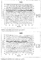
- the values In A(f min. ,f max. ) thus obtained for the logarithmic integral are recorded for the various batches of mixtures R1M1 to R4M1 and R5M2 as a function of time t.
- the Standard deviation ⁇ of the relative damping coefficients ⁇ rel. (f min. ,f max. ) according to Eq. (1d) determined.
- Vs The speed of sound Vs is determined from the distance x and the time t oF up to the first voltage amplitude.
- the time tus 4.6 ⁇ s of the ultrasonic sound signal in advance of the ultrasonic transducer must be taken into account according to Eq. (2) become.
- V S x / t oF ⁇ t U.S
- the viscosity was determined according to Mooney ML1+4 (100°C) as a non-representative offline standard quality control.
- Table 4 Measurement of the extruded batches from Table 3 Extruded batch after 1st mixing stage 2nd mixing stage batch R1M1 R2M1 R3M1 R4M1 R5M2 standard process control Mooney Viscosity ML1+4 (100°C) [MU] 143 150 151 not measurable 122 measurement conditions pressure p [bar] 31 ⁇ 3 34 ⁇ 1 35 ⁇ 1 38 ⁇ 1 34 ⁇ 2 T1 [°C] 124 ⁇ 1 125 ⁇ 1 125 ⁇ 1 124 ⁇ 1 124 ⁇ 1 T2 [°C] 122 ⁇ 1 122 ⁇ 1 122 ⁇ 1 121 ⁇ 1 121 ⁇ 1 ultrasonic characteristics V s Rel.
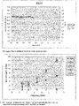
- Table 4 shows that the values for the relative soundproofing ⁇ rel. from 4 MHz of batch R1M1 are significantly smaller than the values of batches R2D1, R3M1 and R4M1 ( 9 ).
- the ejection temperature TA of batch R1M1 is above 140°C, allowing the silanization reaction to take place.
- the ejection temperature TA of batches R2M1, R3M1 and R4M1 was below 140°C so that no silanization reaction could take place.
- Below 4 MHz the difference is relative to the standard deviation ⁇ of the values for the relative noise reduction coefficient ⁇ rel. (f min. ,f max. ) rather small, so that no clear statement is possible.
- the values for the coefficient of variation of the mixtures R3M1 and R4M1 are all less than 0.2%. Apparently, the higher energy input during the kneading process for batches R3M1 and R4M1 leads to improved filler dispersion due to the lower temperature. Nevertheless, the values for In A.(f min. ,f max. ) of batches R3M1 and R4M1 are lower than for R1M1 and R5M2. Since batches with the same composition were used and no significant changes in the measurement conditions (same values for p, T1, and T2) were observed in the inline quality control, the different relative sound absorption coefficients ⁇ rel. (f min. ,f max. ) can only be explained with a chemical reaction of the silica surface with the silane.
- the relative noise reduction coefficient ⁇ rel decreases. (f min. ,f max ) further if the silanization is completed according to the standard method ⁇ in a second mixing step (comparison R1M1 and R5M2).
- the values for the relative soundproofing coefficient ⁇ rel. (f min. ,f max. ) at a frequency > 4 MHz correlate with the values for the Mooney viscosity ML1+4 (100°C) as offline standard method for quality control for non-crosslinked rubber compounds ( 10 ). This obviously shows that the quality of the in situ silanization with the help of the determination of the relative sound absorption coefficient ⁇ rel. (f min. ,f max. ) can be determined.
Landscapes
- Chemical & Material Sciences (AREA)
- Organic Chemistry (AREA)
- Health & Medical Sciences (AREA)
- Chemical Kinetics & Catalysis (AREA)
- Medicinal Chemistry (AREA)
- Polymers & Plastics (AREA)
- Physics & Mathematics (AREA)
- Life Sciences & Earth Sciences (AREA)
- Analytical Chemistry (AREA)
- Biochemistry (AREA)
- General Health & Medical Sciences (AREA)
- General Physics & Mathematics (AREA)
- Immunology (AREA)
- Pathology (AREA)
- General Chemical & Material Sciences (AREA)
- Compositions Of Macromolecular Compounds (AREA)
- Processes Of Treating Macromolecular Substances (AREA)
- Investigating Or Analyzing Materials By The Use Of Ultrasonic Waves (AREA)
Description
- Die Erfindung betrifft das technische Gebiet der Silanisierung von hellen Füllstoffen. Unter hellen Füllstoffen versteht der Fachmann mineralische natürliche und synthetische Füllstoffe, welchen nicht auf Ruß basieren, wie z.B. Glimmer, Kaoline, Kreiden, Calciumcarbonaten, Talk, Zinkoxide, Aluminiumoxide, Titandioxide, Kieselsäure und Silikaten. Zur Verbesserung der Verarbeitbarkeit werden die hellen Füllstoffe durch Silanisierung hydrophobiert, wodurch sich die Eigenschaften der elastomeren Vulkanisate deutlich verbessern. Insbesondere in Kautschukmischungen für Reifenlaufflächen führt die Verwendung von silanisierten Füllstoffen im Vergleich zum schwarzen Füllstoff Ruß zu einer Verbesserung der Nassrutschfestigkeit und des Rollwiderstands, ohne den Abrieb des Reifens zu erhöhen.
- Bei der Herstellung von z.B. Reifenlaufflächenmischungen wird die Kieselsäure mit einem Silanisierungsmittel in einem 1. Mischschritt im Kautschuk in einem Innenmischer diskontinuierlich dispergiert. Der Mischprozess wird dabei durch Einstellung der Mischparameter (Drehzahl, Füllgrad, Temperierung, etc.) so gefahren, dass die Auswurftemperatur im Bereich von 140°C bis 160°C liegt. In einem zweiten Mischschritt im Innenmischer wird die Mischung noch einmal im Bereich von 140°C bis 160°C homogenisiert. Unterhalb von 140°C findet keine Reaktion des Silans mit der Kieselsäure statt, oberhalb von 160°C zersetzt sich das Silan (vgl. z.B. F. Röthemeyer, F. Sommer; "Kautschuktechnologie Werkstoffe, Verarbeitung Produkte", Hanser Verlag 2. Überarbeitete Auflage; ISBN 10: 3-446-40480-5; Seite 272). Als Innenmischer kommen in der Gummiindustrie auch Innenmischer mit einem Austragsextruder zur Anwendung. Neben diskontinuierlichen Herstellungsverfahren werden auch kontinuierliche Verfahren mit Extrudern getestet wie in der
DE69728538T2 offenbart. Die Silanisierung in einer Kautschukmischung wird als in situ Silanisierung bezeichnet. Dieses ist beispielsweise beschrieben inEP-A-0911359 wie auch inEP-A- 1 357156 . - Da die Temperaturen und Mischzeiten bei der in situ Silanisierung exakt eingehalten werden müssen, sind diese Verfahren sehr störanfällig. Prüfungen sollten daher möglichst schnell (inline), volumetrisch und repräsentativ durchgeführt werden. Nur in diesem Fall kann die in situ Silanisierung zuverlässig gesteuert, die thermische Belastung der Kautschukmischung niedrig und die Verfahrenseffizienz hoch gehalten und die Ausschussraten reduziert werden. Dies gilt umso mehr beim kontinuierlichen Verfahren zur in situ Silanisierung, welche sich auch wegen der unzureichenden Möglichkeit der inline Prüfung noch nicht auf dem Markt durchsetzen konnte.
- Entgegen den Anforderungen zur Kontrolle der in situ Silanisierung können Messungen von unvernetzten Kautschukmischungen in der Gummiindustrie in der Regel erst mehrere Minuten oder sogar Tage nach der Herstellung der Kautschukmischung, durchgeführt werden (sogenannte offline Verfahren), da die Messungen zeitintensiv sind und eine zeitgleiche Messung von mehreren Proben eine Vielzahl teurer Messaparaturen erfordert. Daher wird die Qualität einer unvernetzten Kautschukmischung bislang lediglich stichprobenartig (< 0,1% der Gesamtmenge) überprüft. Typischerweise wird die Mooney-Viskosität der Stichproben der Kautschukmischung ermittelt, um die Vollständigkeit der Silanisierungsreaktion zu überprüfen (vgl. F. Röthemeyer, F. Sommer; "Kautschuktechnologie Werkstoffe, Verarbeitung Produkte", Hanser Verlag 2. Überarbeitete Auflage; ISBN 10: 3-446-40480-5; Seite 390). Die geringe Anzahl der Stichproben ist jedoch nicht repräsentativ für die gesamte Kautschukmischung. Zudem können die beschriebenen Möglichkeiten der Qualitätskontrolle verfahrensbedingt bislang nicht automatisiert durchgeführt werden, was den Zeitaufwand erhöht.
- Für die Analyse von mit Extrudern compoundierten Kunststoffen sind eine Vielzahl repräsentativer inline Qualitätskontrollen bekannt, zum Beispiel NIR, Raman und UV/VIS Spektroskopie, bei denen die Proben durchstrahlt werden (vgl. Hochrein et al., Plastverarbeiter, Sept. 2009, S. 92). Bei Verwendung elektromagnetischer Wellen stört jedoch der Ruß, da die elektromagnetischen Wellen schon bei sehr geringen Anteilen von Ruß nahezu vollständig absorbiert werden. Bei Verwendung von mechanischen Druckwellen im hohen Frequenzbereich > 1 MHz (Ultraschallwellen) stört Ruß hingegen vergeleichsweise wenig. Hier sind jedoch helle Füllstoffe mit einer hohen Dichte wie Kieselsäure, Kaolin oder Kreide störend (vgl. A. Schröder, L. Gräff. L. Wawrzinski , Rubber World 251 (2015) 28), da diese die Ultraschallwellen stärker dämpfen als Ruß mit einer niedrigeren Dichte. Zudem besitzen unvernetzte Kautschuke im Gegensatz zu Kunststoffen aufgrund ihrer viskoelastischen Eigenschaften an sich schon eine relative hohe Dämpfung. Aufgrund dieser hohen Dämpfung gibt es bei volumetrischen Messungen in Transmission eine obere Grenze für den Abstand zwischen dem sendenden und dem empfangenden Ultraschallwandler. Wird diese Grenze überschritten, ist das Signal/Rauschverhältnis zu schlecht um verwertbare Messwerte zu erhalten.
- Auf der anderen Seite gibt es eine untere Grenze, da die hochviskose Kautschukmischung noch zwischen den Ultraschallwandlern hindurch fließen muss. So wird in Rubber World 251 (2015) 28 die Verwendung von Ultraschall als inline Qualitätskontrolle für die Detektion von variierenden Anteilen an Füllstoff und Vernetzerbatches mit Markern sowie der Detektion von Verunreinigungen größer als 100 µm und der Makrodispersion von Füllstoffen beschrieben, allerdings nur bis zu einem Anteil von 30 phr an hellen Füllstoffen. Der Anteil an hellen Füllstoffen in Kautschukmischungen für Reifenlaufflächen liegt in der Regel oberhalb von 60 phr, was zu einer Zunahme der Viskosität der Kautschukmischung führt. Zudem wurde die Verwendung von Ultraschall zur Kontrolle einer chemischen Reaktion der in situ Silanisierung weder offenbart noch nahegelegt.
- Die Verfolgung einer chemischen Reaktion, nämlich die Vernetzung eines unvernetzten Kautschuks mit Schwefel, wird in M. Jaunich, B. Stark, B. Hoster, Polymer Testing 28 (2009) 84 beschrieben. Hierbei wird jedoch die Änderung der Vernetzungsdichte mit Hilfe der Schallgeschwindigkeit und nicht der relative Schalldämpfungskoeffizient verfolgt. Dabei werden Ultraschallwandler mit einer Mittenfrequenz von f=4 MHz verwendet. Eine Extrusion der Mischung findet nicht statt.
- Es bestand daher Bedarf an einem repräsentativen inline Verfahren zur Überprüfung der in situ Silanisierung von hellen Füllstoffen. Das Verfahren sollte eine inline Kontrolle der in situ Silanisierung von hellen Füllstoffen, insbesondere Kieselsäuren erlauben. Dabei sollte mit möglichst geringem Zeitversatz festgestellt werden können, ob und in wie weit die Silanisierung der Füllstoffoberfläche stattgefunden hat. Vorzugsweise sollte das Ergebnis der Qualitätskontrolle spätestens eine Minute nach Austritt aus dem Extruder vorliegen, um so eine umgehende Rückkopplung zur Verfahrenssteuerung zu erlauben und eine Steigerung der Produktivität und/oder eine Verringerung der Ausschussraten des Prozesses zu ermöglichen. Bevorzugt sollte das Verfahren auch eine repräsentative Kontrolle erlauben, d.h. eine Überprüfung von wenigstens 1% der silanisierten hellen Füllstoff enthaltenden Kautschukmischung ermöglichen, vorzugsweise unter Produktionsbedingungen, d.h. bei Durchsätzen von ≥ 5 kg/h besonders bevorzugt 50 kg/h. Von besonderem Vorteil wäre dabei ein zerstörungsfrei erfolgendes Verfahren. Um eine Verwendung des Verfahrens bei der Produktion von Kautschukmischungen für Reifen zu ermöglichen wäre es wünschenswert, dass Ruß als zusätzlicher Bestandteil der Kautschukmischung die Qualitätskontrolle nicht oder nur in geringem Umfang stört.
- Überraschend wird die Aufgabe gelöst durch ein Verfahren zur Prüfung der Silanisierung von hellen Füllstoffen, wobei eine Mischung enthaltend mindestens einen silanisierten hellen Füllstoff aus der Gruppe der Kieselsäuren, vorzugsweise der gefällten Kieselsäuren, oder der Dual Phase Filler und mindestens einen Kautschuk extrudiert, das dadurch erhaltene Extrudat mit Ultraschallwellen im Frequenzbereich von 4 bis 10 MHz beschallt und die Signalstärke der Ultraschallwellen nach Transmission durch das Extrudat ermittelt wird. Daraus kann die Schallwellenamplitude und/oder Schallwellenintensität der Ultraschallwellen nach Transmission durch das Extrudat bestimmt werden. In einer bevorzugten Ausführungsform wird der relative Dämpfungskoeffizient αrel des Extrudats im Frequenzbereich der Ultraschallwellen bestimmt.
- Bevorzugt liegt die Temperatur des Extrudats während der Beschallung oberhalb des Glasübergangsbereiches der Kautschukmischung im Frequenzbereich der Ultraschallwellen. Typischerweise liegt die Temperatur des Extrudats mindestens bei 100°C.
- Bevorzugt beträgt der Druck im Extrudat während der Beschallung mindestens 10 bar.
- Bevorzugt werden Ultraschallwellen im Frequenzbereich von 5 bis 7 MHz verwendet. Zur Messung können Ultraschalwellen einer oder mehrerer Frequenzen f verwendet werden. Bei der Beaufschlagung mit einem Frequenzspektrum ist die Verwendung von Ultraschallwellen im Bereich von z. B. von 5 bis 7 MHz typischerweise so zu verstehen, dass bei der emittierten Ultraschallfrequenz f das arithmetische Mittel der Grenzfrequenzen, also der unteren und der oberen Frequenz, bei der die Ultraschallwellenamplitude bzw. die Ultraschallwellenintensität 50% des Maximalwerts beträgt, von 5 bis 7 MHz liegt.
- Im Sinne der vorliegenden Erfindung kann die Prüfung der Silanisierung sowohl die qualitative Bestimmung der Silanisierung als auch die quantitative Bestimmung des Silanisierungsgrads des Füllstoffs umfassen.
- Bei dem Extrudat handelt es sich typischerweise um eine unvernetzte Kautschukmischung, welche vorzugsweise keine Vernetzungsmittel enthält.
- Als Kautschuke eignen sich insbesondere Naturkautschuk (NR), Isoprenkautschuk (IR), Styrol-Butadien-Kautschuk (SBR), Butadienkautschuk (BR), Isopren-Isobutylen-Kautschuk (IIR), Polychloroprenkautschuk (CR), Acrylnitril-Butadien-Kautschuk (NBR), hydrierter Acrylnitril-Butadien-Kautschuk (HNBR), carboxylierter Acrylnitril-Butadien-Kautschuk (XNBR), hydrierter carboxylierter Acrylnitril-Butadien-Kautschuk (HXNBR), Ethylen-Propylen-Dien-Kautschuk (EPDM), Ethylen-Propylen-Kautschuk (EPM), Fluorkautschuk (FKM), perfluorierter Fluorkautschuk (FFKM), Acrylat-Ethylen-Kautschuk (AEM), Acrylatkautschuk (ACM), Ethylen-Methylen-Acrylatkautschuk (EMA), chloriertes Polyethylen, chlorsulfoniertes Polyethylen, Ethylen-Vinylacetat-Kautschuk (EVA), Siliconkautschuk, Fluro-Silicon-Kautschuk, Ethylen-Epichlorhydrin Kautschuk (ECO), Epichlorhydrin-Kautschuk (CO) und/oder Polyurethan-Kautschuk (PU). Besonders bevorzugt sind Naturkautschuk (NR), Isoprenkautschuk (IR), Styrol-Butadien-Kautschuk (SBR), Butadienkautschuk (BR),
- Bevorzugte helle Füllstoffe im Sinne der Erfindung sind gefällte Kieselsäuren. In einer speziellen Ausführungsform der vorliegenden Erfindung können sogenannte Dual Phase Fillers als heller Füllstoff eingesetzt werden. Dabei handelt es sich um Rußpartikel mit einem einem Anteil von > 5% an Kieselsäuren, welche dem Fachmann bekannt sind.
- Der Füllstoffanteil in der Kautschukmischung beträgt typischerweise 50 bis 250 phr, vorzugsweise 60 bis 150 phr und besonders bevorzugt 70 bis 100 phr.
- In einer Ausführungsform des erfindungsgemäßen Verfahrens werden die Extrudate mit mindestens einem Paar, vorzugsweise mit mindestens einem Detektionsband von wenigstens zwei Paaren Ultraschallwandlern analysiert. Die jeweiligen Wandler eines Paares sind gegenüberliegend, die Paare sind in Reihe nebeneinander angeordnet. Der Abstand zwischen den Wandlern eines Paares beträgt vorzugsweise mehr als 5 mm bis 30 mm, besonders bevorzugt von 10 bis 25 mm und meist bevorzugt 15 bis 20 mm.
- Ein Ultraschallwandler eines Paares fungiert dabei als Sender und der andere Wandler als Empfänger des Ultraschallsignals. Im Sender werden Spannungspulse, generiert in der Prüfelektronik, mit Hilfe des piezoelektrischen Effektes in Ultraschallwellen umgewandelt. Typerweise weist ein Spannungspuls bei der Anregung des Senders die Form eines Rechteckpulse oder eines Nadelpulses auf. Bevorzugt werden mindestens zwei Spannungspulse (Burst-Signal) hintereinander mit einem zeitlichen Abstand ≥ 0,01 µs verwendet, besonders bevorzugt werden mindestens sieben Spannungspulse, ganz besonders bevorzugt werden mindestens vierzehn Spannungspulse verwendet. Besonders bevorzugt entspricht der reziproke zeitliche Abstand zwischen den Spannungspulsen eines Burst-Signales der Eigenfrequenz der verwendeten Ultraschallwandler. Das Aussenden eines Ultraschallsignales bestehend aus einem einzelnen Spannungspuls bzw. aus Burst-Signalen wird bevorzugt mit einer Frequenz von mindestens 1 Hz wiederholt, besonders bevorzugt mindestens 10 Hz. Im Empfänger werden die Ultraschallwellen während der Extrusion nach Durchschallung (Transmission) durch die Kautschukmischung wieder in Spannungssignale umgewandelt und können zeitnah (in weniger als 1 min) ausgewertet werden.
- Im Spalt zwischen den Ultraschallwandlern befindet sich das Extrudat. Dabei besteht vorzugsweise ein direkter Kontakt zwischen den Ultraschallwandlern und dem Extrudat.
- Der Spalt ist vorzugsweise an den Seiten begrenzt, wodurch ein Fließkanal mit einer Höhe von ≥ 5 mm, besonders bevorzugt mit einer Höhe von ≥ 10 mm ganz besonders bevorzugt mit einer Höhe von ≥ 20 mm entsteht. Vorzugsweise beträgt die Breite des Fließkanals ≥ 20 mm, besonders bevorzugt ≥ 50 mm, ganz besonders bevorzugt ≥ 100 mm. Das Extrudat durchläuft mit einer Geschwindigkeit von vorzugsweise 0,1 m/min. oder mehr, besonders bevorzugt 1 m/min. oder mehr, ganz besonders bevorzugt 10 m/min. oder mehr das Detektionsband. Hierfür wird vorzugsweise ein Extruder verwendet. Dabei wird ein Teil der Kautschukmischung, vorzugsweise ≥ 1%, bevorzugt ≥ 10% besonders bevorzugt 100% der extrudierten Kautschukmischung mit dem Ultraschall analysiert. Auf diese Weise ist eine repräsentative und nicht nur stichprobenartige Qualitätskontrolle von Kautschukmischungen möglich.
- In einer Ausführungsform der Erfindung wird die Amplitude der in Spannungssignale umgewandelten Schallwellen in Abhängigkeit der Zeitspanne seit dem Aussenden des Schallsignales im Sender gemessen. Diese sogenannte A-Scans werden in Abhängigkeit der Zeit registriert.
- In einer Ausführungsform der Erfindung wird zur Quantifizierung der Signalstärke der Ultraschallwellen aus dem Ultraschallsignal eines A-Scans der Wert einer Ultraschallwellenamplitude, vorzugsweise die maximale Ultraschallwellenamplitude, ermittelt und der Logarithmus der Ultraschallwellenamplitude a gegen die Zeit t dargestellt.
- Vorzugsweise wird das Ultraschallsignal eines A-Scans und nicht die Echos des Ultraschallsignales ausgewertet.
- In einer weiteren Ausführungsform der Erfindung wird durch Quadrieren der Ultraschallwellenamplitude a die Ultraschallwellenintensität i ermittelt und der Logarithmus der Ultraschallwellenintensität i gegen die Zeit t dargestellt..
- Bevorzugt wird der relative Dämpfungskoeffizient αrel. gemäß der Formel (1a)

- In einer weiteren Ausführungsform der Erfindung werden die Werte des Ultraschallsignales quadriert und anschließend integriert und so die integrale Ultraschallwellenintensität I ermittelt. Alternativ kann die integrierte Ultraschallwellenamplitude A aus der Quadratwurzel der Ultraschallwellenintensität I ermittelt werden.
- Besonders bevorzugt wird der relative Dämpfungskoeffizient αrel. gemäß der Formel (1b) mit Hilfe der integrierten Ultraschallwellen Intensität I und bzw. der integrierten Ultraschallwelenamplitude ermittelt.

- In einer bevorzugten Ausführungsform der Erfindung wird mit Hilfe der Fast Fourier Transformation (FFT) das Frequenzspektrum a(f) des Ultraschallwellenamplitude bzw. der Ultraschallwellenintensität i(f) ermittelt.
- Bevorzugt wird der relative Dämpfungskoeffizient αrel. in Abhängigkeit der Frequenz f gemäß der Formel (1c)

- In einer besonders bevorzugten Ausführungsform der Erfindung wird das Frequenzspektrum in Frequenzbereiche mit einer minimalen Frequenz von fmin. und einer maximalen Frequenz fmax unterteilt und integriert. Bevorzugt enthalten diese Frequenzbereiche ein Maximum der Ultraschallwellenamplitude bzw. der Ultraschallwellenintensität.
- Bevorzugt wird der relative Dämpfungskoeffizient αrel. in Abhängigkeit des Frequenzbereiches von einschließlich fmin. bis einschließlich fmax. gemäß der Formel (1d)

- Alternativ kann der relative Dämpfungskoeffizient αrel. aus der Ultraschallwellenintensität i, Ultraschallwellenintensität irel einer Referenz und dem Abstand x gemäß der Formel (1b) ermittelt werden.
- Bevorzugt wird der relative Dämpfungskoeffizient αrel bei der Eigenfrequenz der Ultraschallwandler ermittelt.
- In einer Ausführungsform der Erfindung wird die Signalstärke des Ultraschallwellensignals der Referenz durch die Extrusion einer Kautschukmischung von mindestens 1 kg bei vergleichbaren Prozess- und Messbedingungen während der Extrusion ermittelt. Vergleichbare Prozess- und Messbedingungen während der Extrusion und der Messung liegen dann vor, wenn die Änderungen des Durchsatzes kleiner als 10%, die Änderungen der Temperatur des Extrudats zwischen den Ultraschallwandlern und der Ultraschallwandler kleiner als < ± 5 K und Änderungen des Druckes p im Extrudat zwischen den Ultraschallwandlern kleiner als < ± 5 bar sind. Bevorzugt sind Prozess- und Messbedingungen wenn die Änderungen des Durchsatzes kleiner als 5%, die Änderungen der Temperatur des Extrudates zwischen den Ultraschallwandlern und der Ultraschallwandler kleiner als < ± 2 K und Änderungen des Druckes im Extrudat zwischen den Ultraschallwandlern kleiner als < ± 2 bar sind. Besonders bevorzugt sind Prozess- und Messbedingungen wenn die Änderungen des Durchsatzes kleiner als 2%, die Änderungen der Temperatur des Extrudates zwischen den Ultraschallwandlern und der Ultraschallwandler kleiner als < ± 1 K und Änderungen des Druckes im Extrudat zwischen den Ultraschallwandlern kleiner als < ± 1 bar sind.
- Besonders bevorzugt wird als Referenzmischungen eine Kautschukmischung mit gleicher Zusammensetzung verwendet, wie die zu überprüfende Kautschukmischung, wobei bei der Referenzmischung die Silanisierung optimal durchgeführt wurde.
- In einer bevorzugten Ausführungsform wird der Abstand x zwischen den Ultraschallwandlern mit Hilfe eines Innentasters mit einer Genauigkeit von besser als 0,1 mm ermittelt.
- In einer weiteren Ausführungsform der Erfindung wird zudem der Variationskoeffizient (Coefficient of Variation CV) des Logarithmus der Ultraschallwellenamplitude bzw. der Ultraschallwellenintensität ermittelt. Bevorzugt werden dabei weniger als 1000 Messwerte, besonders bevorzugt weniger als 100 Messwerte ganz besonders bevorzugt weniger als 10 Messwerte verwendet.
- In einer bevorzugten Ausführungsform wird neben dem relativen Dämpfungskoeffizienten die Standardabweichung σ des relativen Dämpfungskoeffizienten ermittelt. Bevorzugt werden dabei weniger als < 1000 Messwerte, besonders bevorzugt weniger als 100 Messwerte ganz besonders bevorzugt weniger als 10 Messwerte verwendet.
- In einer weiteren Ausführungsform wird neben dem relativen Dämpfungskoeffizienten die Schallgeschwindigkeit Vs des Extrudates gemäß Formel (2) ermittelt.

- Die Zeitspanne toF benötigt das Ultraschallsignal vom Zeitpunkt des Ausendens im Sender bis zum empfangen im Empfänger. Die Zeitspanne tus benötigt das Ultraschallsignal in den Ultraschallwandlern. Die Zeitspanne tus wird bei vergleichbaren Temperaturen für Ultraschallwandler wie während der Extrusion ermittelt. Die Ermittlung der Zeitspanne tus erfolgt durch Bestimmung von toF bei variierendem Abstand x der Ultraschallwandler. Dabei wird bevorzugt die Referenzmischung zwischen den Ultraschallwandlern verwendet. Bevorzugt werden mindestens vier Abstände im Bereich von 5 mm bis 30 mm eingestellt. Die Zeitspanne tus ergibt sich aus dem Achsenabschnitt einer linearen Regression der Auftragung von toF gegen den Abstand x der Ultraschallwandler.
- Ungenügend silanisierte helle Füllstoffe führen zu einer Erniedrigung der Ultraschallwellenamplitude a bzw. der Ultraschallintensität i am Empfänger und einer Erhöhung des relativen Dämpfungskoeffizienten αrel. Die Schallgeschwindigkeit Vs bleibt unverändert. Der Variationskoeffizient CV bzw. die Standardabweichung σ des relativen Schalldämpfungskoeffizienetn αrel. gibt die Homogenität der Kautschukmischung wieder.
- In einer bevorzugten Ausführungsform durchläuft der Kautschuk ein Detektionsband aus einem oder mehreren Ultraschallsensorpaaren, die über die gesamte Breite des Fließkanals angeordnet sind.
- In einer besonders bevorzugten Ausführungsform durchläuft die Kautschukmischung zwei Detektionsbänder, die leicht versetzt angeordnet sind. Hierdurch wird gewährleistet, dass die komplette Kautschukmischung analysiert wird.
- Bevorzugte Ausführungsformen der erfindungsgemäßen Vorrichtung sind in
Fig.1 bis Fig. 3 dargestellt.Fig. 1 beschreibt exemplarisch das Detektionsband, bestehend aus den Ultraschallsensorpaaren (4), d.h. pro Paar jeweils ein Sender und ein Empfänger und dem Fließkanal (5) in Aufsicht, inFig. 2 ist die Anordnung inFig. 1 in Seitenansicht dargestellt.Fig. 3 zeigt eine Anordnung aus einem Extruder (1), dem Detektionsband, bestehend aus den Ultraschallwandlerpaaren (4) und dem Fließkanal (5) und der Ultraschallprüfelektronik (2) sowie einem Rechner als Auswerteeinheit (3). - Gegenstand der Erfindung ist zudem ein Verfahren zur Herstellung von silanisierte helle Füllstoffe enthaltenden Kautschukmischungen, wobei mindestens ein heller Füllstoff aus der Gruppe der Kieselsäuren, vorzugsweise der gefällten Kieselsäuren oder der Dual Phase Filler mit mindestens einem Kautschuk und mindestens einem Silanisierungsmittel gemischt und silanisiert wird und wobei zumindest ein Teil der erhaltenen Kautschukmischung durch das erfindungsgemäße Verfahren zur Prüfung der Silanisierung geprüft wird. Vorzugsweise werden mehr als 1 Vol.-%, besonders bevorzugt mehr als 10 Vol.-%, meist bevorzugt 100 Vol.-% der erhaltenen Kautschukmischung durch das erfindungsgemäße Verfahren zur Prüfung der Silanisierung geprüft. Das erfindungsgemäße Verfahren kann dabei kontinuierlich oder als Batchverfahren, vorzugsweise kontinuierlich betrieben werden.
- In einer weiteren bevorzugten Ausführungsform des erfindungsgemäßen Verfahrens wird der Extruder gleichzeitig als Mischaggregat für die Herstellung der Kautschukmischung, nebst in situ Silanisierung und zur Herstellung des Extrudats gemäß dem erfindungsgemäßen Prüfungsverfahren verwendet. Hierbei wird mindestens je ein heller Füllstoff, ein Silanisierungsmittel und ein Kautschuk dem Extruder zugeführt und in diesem aus dem Silanisierungsmittel und dem hellen Füllstoff der silanisierte Füllstoff gebildet.
- Bevorzugt wird als Silanierungsmittel mindestens ein Silan verwendet. Als Silane im Sinne der Erfindung gelten Verbindungen, die Silizium und Wasserstoff sowie weitere Atome anderer chemischer Elemente enthalten. Bevorzugt sind Silane mit Trilalkoxysilygruppen. Weiter bevorzugt sind bifunktionelle Silane, bei denen eine funktionelle Gruppe mit der Oberfläche eines hellen Füllstoffs reagieren kann, z.B. Trialkoxsilygruppen und die andere funktionelle Gruppe an der Vernetzungsreaktion des Kautschuks teilnehmen kann, wie zum Beispiel Vinyl, Thiol, oder Polysulfangruppen.
- Ganz besonders bevorzugt sind folgende Silane:
Bis(3-triethoxysilypropyl)tetrasulfid (Si69), Bis(triethoxysilylpropyl)disulfid (Si75), Bis(triethoxysilylpropyl)disulfid (Si266), 3-Thiocyanatopropyltriethoxysilan (Si264), VP Si 363® (von Evonik Industries), Vinylthriethoxysilan, Vinyltris(betamethoxyethoxy)silan, Gammamercaptopropyltrimethoxysilan, Gammaaminopropylthrimethoxysilan, Gammaglycidoxypropylthrimethoxysilan, Aminoethylgammaaminopropyltrimethoxysilan, triaminofunktionelle Silane, Gammachlorpropyltriethoxysilan, Tris(1-methoxyethoxypropyl-2-oxy)vinylsilan. - Bei der Silanisierung handelt es sich um eine chemische Anbindung eines Silans an die Oberfläche des hellen Füllstoffs. Die Anbindung erfolgt durch Kondensationsreaktionen zwischen hydrolysierbaren Gruppen der verwendeten Silane und chemischen Gruppen an der Oberfläche des Füllstoffs. Die Silanisierung des hellen Füllstoffes wird vorzugsweise in einer Kautschukmischung (in situ Silanisierung) bei Temperaturen im Bereich von 140°C bis 160°C durchgeführt. Hierfür werden jeweils mindestens ein Kautschuk, Silan und heller Füllstoff vermischt und einer Temperatur im oben angegeben Bereich ausgesetzt.
- Die Kautschukmischung enthält dabei typischerweise 5 bis 15 Gew.-% Silanierungsmittel bezogen auf den Gesamtanteil an hellen Füllstoffen.
- Die Kautschukmischungen können dabei weitere Füllstoffe, weitere Additive wie Alterungsschutzmittel, Weichmacher, etc., Vernetzungsmittel, Vulkanisationsbeschleuniger und/oder Vulkanisationsverzögerer und/oder weitere Hilfsmittel enthalten.
- Weitere Füllstoffe sind z.B. Kohlenstoff-basierte Füllstoffe, wie z.B. Ruß, Graphit, Carbon Nanotubes, sowie magnetisierbare Füllstoffe wie Carbonyl-Eisenpulver, Eisenoxide, Ferrite und/oder Fasern wie z.B. Aramidfaserpulpe und Kohlefasern.
- Als Alterungsschutzmittel sind verfärbende und nicht verfärbende Alterungsschutzmittel, wie z.B. Paraphenylendiamine, Isopropylphenylparaphenylendiamin (IPPD), Para-Phenylen-Diamin (6PPD), N,N-ditoly-p-phenylendiamin (DTPD), etc., Amine, wie z.B. Trimethyl-1,2-dihydrochinolin (TMQ), (Phenyl)amine]-1,4-naphthalendion (PAN), Bis(4-octylphenyl)amin (ODPA), styrolisiertes Diphenylamin (SDPA), Mono- und Bisphenole, wie z.B. 2,2'-Methy)en-bis-(4-methyl-6-tert.butyipheno) (BPH), 2,2'-Isobutyliden-bis-(4,6-dimethyl-phenol) (NKF), 2,2'-Dicyclo-pentadienyl-bis-(4-methyl-6-tert.-butyl-phenol) (SKF), 2,2'-Methylen-bis-(4-methyl-6-cyclohexyl-phenol (ZKF), 2,6-Di-tert.-butyl-p-kresol (BHT), substituiertes Phenol (DS), styrolisierte Phenole (SPH), Mercatobenzimidazole, wie z.B. 2-Mercaptobenzimidazol (MBI), 2-Mercaptomethyl-benzimidazole (MMBI), Zink-4- und -5-methyl-2-mercapto-benzimidazole (ZMMBI) geeignet.
- Weichmacher sind z.B. langkettige Ester und/oder Ether, wie Thioester, Phthalsäureseter, Alkylsulfonsäureester, Adipinsäureester, Sebacinsäuresester, Dibenzylether, und/oder Mineralöle (paraffinische, aromatische naphthenische oder synthetische Öle).
- Vernetzungsmittel im Sinne der Erfindung sind Netzknotenbildner. Netzknotenbildner sind Moleküle, die zwei einzelne Polymerketten mit einander verbinden können, wie z.B.
- Schwefel (löslich oder unlöslich) und/oder Schwefelspender, wie z.B. Dithiomorpholine (DTDM), Tetramethylthiuramdisulphide (TMTD), Tetraethylthiuramdisulphid (TETD), Dipentamethylenthiuramterasulphide (DPTT), Phosphorylpolysulfide, wie z.B. Rhenocure® SDT/S der Firma Rhein Chemie Rheinau GmbH und/oder
- Peroxide, wie z.B. Di-tert.Butyl-Peroxide, Di-(tert,Butyl-Peroxy-Timethyl-Cyclohexane, Di-(tert.-Butyl-peroxy-isopropyl)benzene, Dicumylperoxide, Dimethyl-di(tert.butyl-Peroxy)hexin, Butyl-Di-(tert,Butyl-Peroxy-)valerat,
- Resorcinol, Aldehyd-Amin-Kondensationsprodukte, wie z.B. Hexamethylentetramin, Resorcinol-Formaldehyd-Vorkondensate und/oder Vulkanisationsharze, wie zum Beispiel Halomethylphenolharz,
- Chinondioxime
- Bisphenole.
- Beschleuniger, sind beispielsweise:
- Carbamate bzw. Triazine, wie z.B. Hexamethylendiamincarbamat (HMDC), organische Triazine,
- Thiazole, wie z.B. 2-Mercaptobenzothiazol (MBT), Zinkmercaptobenzothiazol (ZnMBT), Thiadiazole (TDD),
- Sulfenamide, wie Cyclohexyl-benzothiazol-Sulphenamide (CBS), Di-benzothiazyl-disulphid (MBTS), Butyl-benzothiazole-Sulphenamide (TBBS), Dicyclohexyl-Benzothiazol-Sulphenamid (DCBS), 2-(4-Morpholinylmercapto)-benzothiazol (MBS),
- Thiurame, wie Tetramethyl-thiuram-monosulphid (TMTM), Tetraethyl-thiuram-disulphid (TETD), Tetramethyl-thiuram-disulphid (TMTD), Tetrabenzylthiuram Disulphid (TBTD), Dipentamethylene-Thiuram-Tetra(Hexa)-Sulphid (DPTT),
- Dithiocarbamate, wie Zn-Dimethyldithiocarbamate (ZDMC), Cu-Dimethyldithiocarbamate, Bi- Dimethyldithio-carbamate, Zn-Diethyldithiocarbamate (ZDEC), Tellurdiethyldithio-carbamate (TDEC), Zn-Dibuthyldithiocarbamate (ZDBC), Zn-Ethyl-Phenyl-Dithiocarbamate (ZEPC), Zn-Dibenzyl-Dithiocarbamate (ZBEC), Ni-Dibuthyl-Dithiocarbamate (NBC), Selendiethyldithiocarbamate (SeEDC), Selendimethyldithiocarbamate (SeDMC), Tellurdiethyldithiocarbamate (TeEDC),
- Thiophosphat- und Dithiophosphat, wie z.B. Zink-O,O-di-n-butyl-dithiophosphat (ZBDP), Zink-O-butyl-O-hexyl-dithiophosphat, Zink-O,O-diisooctyl-dithiophosphat (ZOPD), Dodecylammonium-diisooctyl-dithiophosphat (AOPD), wie z.B. die Rhenogran®-Typen ZDT, ZAT, ZBOP der Firma Rhein Chemie Rheinau GmbH,
- Harnstoff/Thioharnstoffe, wie z.B. Ethylenthioharnstoff (ETU), N,N,N'N'-Tetramethylthioharnstoff (TMTU), Diethylthioharnstoff (DETU), Dibutylthioharnstoff (DBTU), 3-(3,4-Dichlorphenyl)-1,1-dimethylharnstoff (Diuron) etc., und/oder
- Xanthogenatbeschleuniger, wie z.B. Zinkisopropylxanthogenat (ZIX),
- Guanidine, wie z.B. Diphenylguanidin (DPG) und/oder N',N-di-ortho-tolyl-Guanidin (DOTG) und die Guanidine-frei Ersatzbeschleuniger, wie Rhenogran ® XLA 60,
- Vulkanisationsverzögerer, sind z.B. N-Nitrososdiphenylamin, N-Cylcohexylthiophthalimid (CPT), z.B. Vulkalent® G), Sulfonamidderivate (z.B. Vulkalent® E/C), Phthalsäureanhydrid (z.B. Vulkalent® B/C), oder Benzoesäureanhydrid.
- Hilfsmittel sind z.B. Dispergierhilfsmittel, wie z.B. Fettsäuren, Stearinsäure, Ölsäure, Aktivatoren wie zum Beispiel Zinkoxid, Bleioxid, Bismuthoxid, Lithiumcarbonat, Natriumcarbonat und/oder Calciumhydroxid, Magnesiumoxid, Flammschutzmittel wie Antimonoxid, etc.
- Die vorgenannten Füllstoffe, Additive, Weichmacher, Vernetzungsmittel, Vulkanisationsseschleuniger und/oder Vulkanisationsverzögerer, Hilfsmittel usw. sind dem Fachmann vertraut und können auch in granulierter Form, z.B. als polymergebundene Additive oder als die in
EP2314442A beschriebenen Vernetzerbatches eingesetzt werden. - Die Kautschukmischungen können weiterverarbeitet werden beispielsweise zu Masterbatches, Grundmischungen und vernetzbaren Kautschukmischungen.
- Masterbatches haben typischerweise einen hohen Anteil an Additiven bezogen auf Kautschuk und enthalten beispielsweise:
- 2,5 bis 90 Gew.-% Kautschuk
- 0 bis 50 Gew.-% Weichmacher
- 2 bis 80 Gew.-% silanisierte helle Füllstoffe
- 0 bis 20 Gew.-% Dispergierhilfsmittel
- 0 bis 10 Gew.-% Silan
- Grundmischungen sind Kautschumischungen, denen vor der praktischen Anwendung nur noch Vernetzungsmittel und ggf. Vulkanisationsbeschleuniger zugesetzt werden müssen, beispielsweise:
- 100 phr Kautschuk
- 0 bis 100 phr Weichmacher
- 0 bis 200 phr Füllstoffe, davon mindestens 10% silanisierte helle Füllstoffe
- 0 bis 30 phr Hilfsmittel und
- 0 bis 10 phr Alterungsschutzmittel.
- Vernetzbare Kautschukmischungen sind Kautschukmischungen, die zusätzlich 0.01 bis 20 phr Vernetzungsmittel und optional Vulkanisationsbeschleuniger und Vulkanisationsverzögerer enthalten.
- Besonders bevorzugt sind vernetzbare Kautschukmischungen, die unter anderen 30 bis 110 phr Ruß und gefällte Kieselsäure, 3 bis 9 phr Silan, 2 bis 7 phr Zinkoxid sowie 0,5 phr bis 4 phr Schwefel und 1 bis 5 phr Beschleuniger enthalten.
- Die Erfindung umfasst auch ein Verfahren zur Herstellung von vernetzbaren, silanisierten hellen Füllstoff enthaltenden Kautschukmischungen in dem vor, während und/oder nach der Herstellung der erfindungsgemäßen Kautschukmischung ein oder mehrere Vernetzungsmittel zugefügt werden. Die Vernetzungsmittel können also vor, während und/oder nach dem Mischen des hellen Füllstoffs mit Silanisierungsmittel und Kautschuk zugefügt werden.
- Die Herstellung der Masterbatches, der Grundmischung und der vernetzbaren Kautschukmischung erfolgt vorzugsweise nach den, dem Fachmann geläufigen Verfahren, wie beispielsweise beschrieben in
PCT/EP2009/058041 - In einer weiteren Ausführungsform der Erfindung wird in einem ersten Schritt die Grundmischung in einem Mischaggregat hergestellt. Dabei können Temperaturen von mehr als 140°C bis 160°C erreicht werden. In einem zweiten Herstellungsschritt werden nach Abkühlen der Grundmischung auf Temperaturen kleiner 130°C Vernetzungsmittel zur Grundmischung in einem weiteren Mischaggregat hinzugegeben. Ein Teil der Vernetzungsmittel, Vulkanisationsbeschleuniger und/oder Vulkanisationsverzögerer kann dabei schon im ersten Herstellungsschritt zur Grundmischung hinzugegeben werden.
- In einer weiteren bevorzugten Ausführungsform wird die Grundmischung im ersten Schritt in einem Mischaggregat hergestellt. Dabei können Temperaturen von mehr als 140°C bis 160°C erreicht werden. In einem zweiten Schritt wird die Mischung homogenisiert Dabei können ebenfalls Temperaturen von mehr als 140°C bis 160°C erreicht werden. In einem dritten Herstellungsschritt werden nach Abkühlen der Grundmischung auf Temperaturen kleiner 130°C Vernetzungsmittel zur Grundmischung in einem weiteren Mischaggregat hinzugegeben. Ein Teil der Vernetzungsmittel, Vulkanisationsbeschleuniger und/oder Vulkanisationsverzögerer kann dabei schon im ersten oder zweiten Herstellungsschritt zur Grundmischung hinzugegeben werden.
- Besonders bevorzugt sind dabei kontinuierliche Verfahren, bei denen die Masterbatche, Grundmischungen oder auch die vernetzbaren Kautschukmischungen in einem oder mehreren Prozessschritten mit einem oder mehreren Extrudern hergestellt werden.
- Ganz besonders bevorzugt ist das in
DE-A-102008040138 beschriebene Herstellungsverfahren für vernetzbare Kautschukmischungen, in dem die Grundmischung in mindestens einem diskontinuierlichen Kneterprozess hergestellt wird, und Vernetzungsmittel in Form der in beschriebenenEP-A-2314442 beschriebenen Vernetzerbatche zur Grundmischung hinzugefügt werden und die Vernetzerbatche in einem kontinuierlichen Prozess mit einem Extruder mit der Grundmischung vermischt werden. - Weiterhin betrifft die Erfindung ein Verfahren zur Herstellung von Vulkanisaten umfassend die erfindungsgemäße Herstellung von vernetzbaren, silanisierte helle Füllstoffe enthaltenden Kautschukmischungen und die nachfolgende Vulkanisation bei einer Temperatur im Bereich von 100 °C bis 200 °C.
- Ebenfalls mitumfasst von der Erfindung ist die Verwendung von Messvorrichtungen zur Bestimmung der Ultraschallwellenamplitude a, integrierten Ultraschallwellenamplitude A und/oder der Ultraschallwellenintensität i, der integrierten Ultraschallwellenamplitude I einer oder mehreren Frequenzen in einem Bereich von 4 bis 10 MHz, vorzugsweise von 5 bis 7 MHz für das erfindungsgemäße Prüfverfahren, für die erfindungsgemäßen Herstellungsverfahren von Kautschukmischungen im allgemeinen und vernetzbaren Kautschukmischungen im speziellen. Vorzugsweise umfasst dies auch die Verwendung der genannten Messvorrichtungen zur Bestimmung des relativen Dämpfungskoeffizienten αrel. bei den oben genannten Verfahren.
- Somit stellt die vorliegende Erfindung ein Verfahren zur Überprüfung der Silanisierung, zur Verfügung, welches eine inline Kontrolle der in situ Silanisierung von hellen Füllstoffen, insbesondere gefällten Kieselsäuren erlaubt. Dadurch wird eine kontinuierliche in situ Silanisierung bei der Herstellung von silanisierten hellen Füllstoffen enthaltenden Kautschukmischungen und eine repräsentative Kontrolle der Kautschukmischung unter Produktionsbedingungen ermöglicht. Das Verfahren arbeitet zudem zerstörungsfrei und weist eine hohe Toleranz für Ruß als zusätzlichem Bestandteil der Kautschukmischung auf.
- Die nachfolgenden Beispiele, Abbildungen und Figuren dienen der Erläuterung der Erfindung, ohne dabei limitierend zu wirken.
- Die Komponenten einer typischen Kautschukmischung für Reifenlaufflächen gemäß Tabelle 1 wurden bereitgestellt.
Tabelle 1: Rezeptur einer typischen Kautschukmischung für Reifenlaufflächen Handelsname Dichte [g/cm3] Menge [phr] Buna CB 24 Butylkautschuk Lanxess Deutschland GmbH 0,91 30 Buna VSL 5025-2 HM Lösungs-Styrol-Butadien-Kautschuk Lanxess Deutschland GmbH 0,95 70 CB N-330 Ruß 1,8 5 Ultrasil GR 7000 Kieselsäure Evonik Industries AG 2 90 ASM-TMQ 2,2,4-Trimethyl-1,2-dihydrochinolin 1,1 1,5 ASM-6PPD N-1,3-Dimethylbutyl-N'-phenyl-p-phenylendiamin 1 2 Stearinsäure 0,89 1 Zinkoxid WS Norzinco GmbH 5,6 2 Si-69 Bis-(triethoxy-silyl-propyl)-tetrasulfid Evonik Industries AG 0,866 10 - Diese Komponenten wurden gemäß der Mischvorschrift in Tabelle 2 in verschiedenen Chargen gemischt.
Tabelle 2: Mischvorschrift Zeit Mischungsbestandteil Bemerkung 0-0,75' Polymere 0,75'-1'20" 1'20" Kieselsäure + Si69 + ZnO Stempel oben Stempel ab 2' Alterungsschutzmittel + Stearinsäure 3,5' kehren 5' Auswurf - Bei den Chargen R1M1 bis R5M2 wurden die Mischparameter Drehzahl und Vorlauftemperatur variiert gemäß Tabelle 3.
Tabelle 3: Gemischte Chargen einer typischen Kautschukmischung aus Tabelle 1 1. Mischstufe 2. Mischstufe Batch R1M1 R2M1 R3M1 R4M1 R5M2 Mischparameter Füllgrad [%] 70 70 70 70 70 Drehzahl [U/min.] 70 40 40 40 70 Vorlauftemperatur [°C] 70 70 50 40 70 Mischzeit [min.] 5 5 5 5 3 Energieeintrag [W] 135 134 149 146 110 Auswurftemperatur TA [°G] 147 126 117 112 142 - Die Mischung wird, wie in Tabelle 3 angegeben, im 1,5 I Innenmischer (Intermesh) der Firma Gumix S.A. für 5 min. gemischt. Die Kautschukmischung enthält dabei u.a. Kieselsäure und Silan, sowie etwas Ruß.
- Das Silan reagiert oberhalb von 140°C mit der Kieselsäureoberfläche. Unterhalb von 140°C findet keine Reaktion statt. Durch die verschiedenen Mischparameter werden unterschiedliche Werte für die Auswurftemperatur TA unterhalb (Charge R2M1 bis R4M1) und oberhalb (Charge R1M1 und R5M2) von 140°C erreicht. Die Charge R5M2 wurde zudem noch ein zweites Mal im Innenmischer gemischt, um die Reaktion zu vervollständigen (R5M2). Dies entspricht einem typischen Verfahren für in situ Silanisierungen in der Reifenindustrie. Nach dem Mischprozess im Innenmischer wurden die Mischungschargen auf einer Doppelwalze Firma Rubicon Gummitechnik und Maschinentechnik GmbH bei einer Temperierung von 50°C homogenisiert (dreimal links und dreimal rechts eingeschnitten) und zu einem Mischungsfell ausgezogen. Aus dem Fell wurden Streifen geschnitten. Diese Streifen wurden zu einem Einwellenextruder EEK32.12L der Firma Rubicon Gummitechnik und Maschinentechnik GmbH mit geringer Mischwirkung gefüttert. Am Ausgang des Extruders befindet sich ein Sensorkopf, ausgestattet mit zwei gegenüberliegenden Ultraschallwandlern mit einem Abstand von 10 mm, zudem ein Temperatursensor T1 mit einem Schwert das in den Mischungsfluss hinein ragt und ein Druck-/Temperatur-Sensor. Dieser Temperatursensor misst den Druck p und die Temperatur T2 an der Kautschuk-Metall-Grenzfläche. Der Fließkanal im Sensorkopf hat eine Breite von 20 mm und eine Höhe von 10 mm. Der Durchmesser der Ultraschallwandler beträgt 8 mm. Sensorkopf und Extruder wurden bei 120°C temperiert.
- Die Schneckendrehzahl betrug 20 U/min. Dies entspricht einem Durchsatz von ca. 1 kg Kautschukmischung pro 10 min.
- Die inline Qualitätskontrolle wurde mit einem Paar von Ultraschallwandlern K6V1 der Firma GE Sensing & Inspection Technologies GmbH in Transmission durchgeführt. Die Ultraschallwandler wurden mit der Prüfelektronik PCM 100LAN der Firma Inoson GmbH angesteuert. Es wurden 10 bis 40 Ultraschallpulse pro Sekunde mit Hilfe des piezoelektrischen Effektes im Ultraschallwandler erzeugt. Der Ultraschallwandler wandelt die Spannungspulse in Ultraschallsignale um. Dabei wurden die Ultraschallwandler mit 7 Bursts bei der Eigenfrequenz der Ultraschallwandler von 6 MHz angeregt. Der Ultraschallpuls des Transmitters wandert durch die extrudierte Kautschukmischung und wird dabei durch die Kautschukmischung gedämpft. Die Schwingungsamplitude a des Ultraschallsignales wird erniedrigt. Der Receiver empfängt das Schallsignal und wandelt es in ein Spannungssignal um. Das Spannungssignal wird von der Hardware des PCM100LAN mit 32,45 dB verstärkt und zu einem Rechner geleitet. Mit Hilfe des Rechners wird der erste Schallpuls des sogenannten A-Scans mit der sogenannten Fast Fourier Transformation (FFT) ausgewertet. Das so erhaltene Amplitudenspektrum a(f) in Abhängigkeit der Ultraschallfrequenz f wurde bei fünf unterschiedlichen Frequenzbereichen (vgl. Tabelle 4) integriert und logarithmiert. Die so erhaltenen Werte In A(fmin.,fmax.) für das logarithmierte Integral werden für die verschiedenen Mischungschargen R1M1 bis R4M1 und R5M2 in Abhängigkeit der Zeit t aufgezeichnet. Dies geschieht noch vor Austritt der Mischung aus dem Sensorkopf am Ausgang des Extruders. Die Verweilzeit der Mischung im Sensorkopf betrug weniger als 1 Minute. Das Ergebnis für den Frequenzbereich frmin. = 5,2 MHz bis frmax. = 6,9 MHz ist für jede Mischungscharge in den
Fig. 4 bis 8 dargestellt. Zusätzlich ist der Variationskoeffizient CV zu den Werten In A(fmin.,fmax.) für 50 Messpunkte angegeben. Der Variationskoeffizient CV ist ein Maß für die Mischungsgüte. - Aus den Werten für In A(fmin.,fmax.) wird der relative Dämpfungskoeffzient αrel. (fmin.,fmax.) nach dem Lambert Beer'schen Gesetz berechnet.

- Hierbei ist x der Abstand zwischen den Ultraschallwandlern. In Gl. (1d) ist der Mittelwert von In Aref.(fmin.,fmax.) der Referenzmischung R5M2 (Standardmischverfahren) für eine Zeitspanne für die Extrusion von Δt = 5 min.. In Tabelle 4 sind die Mittelwerte für den relativen Dämpfungskoeffizient αrel.(fmin.,fmax.) für eine Zeitspanne von Δt = 4 min bis Δt = 8 min. für die Extrusion für jede Mischungscharge dargestellt. Zudem wurde die Standardabweichung σ der relativen Dämpfungskoeffizienten αrel.(fmin.,fmax.) nach Gl. (1d) ermittelt. Außerdem ist der Mittelwert des Drucksensors p und die Mittelwerte für der Temperatursensor T1 mit Schwert und T2 ohne Schwert angegeben. Die Schallgeschwindigkeit Vs wird aus dem Abstand x und der Zeit toF bis zur ersten Spannungsamplitude ermittelt. Dabei muss die Zeit tus = 4,6 µs des Ultraschallschallsignales im Vorlauf der Ultraschallwandler berücksichtigt nach Gl. (2) werden.

- Zusätzlich zu den Ultraschallkennwerten wurde die Viskosität nach Mooney ML1+4 (100°C) als nicht-repräsentative offline Standard Qualitätskontrolle ermittelt.
Tabelle 4: Messung der extrudierten Chargen aus Tabelle 3 Extrudierte Charge nach 1. Mischstufe 2. Mischstufe Batch R1M1 R2M1 R3M1 R4M1 R5M2 Standard Prozesskontrolle Mooney Viskosität ML1+4 (100°C) [MU] 143 150 151 nicht messbar 122 Messbedingungen Druck p [bar] 31 ± 3 34 ± 1 35 ± 1 38 ± 1 34 ± 2 T1 [°C] 124 ± 1 125 ± 1 125 ± 1 124 ± 1 124 ± 1 T2 [°C] 122 ± 1 122 ± 1 122 ± 1 121 ± 1 121 ± 1 Ultraschallkennwerte Vs Rel. Dämpf.koeff. αrel. [m/s] 1214 ± 3 1218 ± 2 1220 ± 3 1222 ± 2 1218 ± 3 (1,1 MHz bis 1,7 MHz) [1/m] 1 ± 2 3 ± 2 3 ± 2 2 ± 2 0 ± 1 (1,7 MHz bis 2,8 MHz) [1/m] 3 ± 2 4 ± 2 3 ± 2 2 ± 2 0 ± 2 (2,8 MHz bis 4,0 MHz) [1/m] 4 ± 2 6 ± 2 6 ± 3 4 ± 2 0 ± 2 (4,0 MHZ bis 5,2 MHz) [1/m] 5 ± 2 9 ± 3 9 ± 3 9 ± 2 0 ± 2 (5,2 MHz bis 6,9 MHz) [1/m] 7 ± 3 14 ± 3 15 ± 4 14 ± 2 0 ± 2 - Es zeigt sich in Tabelle 4, dass die Werte für die relative Schalldämpfung αrel. ab 4 MHz der Charge R1M1 signifikant kleiner sind als die Werte der Chargen R2D1, R3M1 und R4M1 (
Fig. 9 ). Die Auswurftemperatur TA der Charge R1M1 liegt oberhalb von 140°C, sodass die Silanisierungsreaktion stattfinden konnte. Die Auswurftemperatur TA der Chargen R2M1, R3M1 und R4M1 lag unterhalb von 140°C, sodass keine Silanisierungsreaktion stattfinden konnte. Unterhalb von 4 MHz ist der Unterschied relativ zur Standardabweichung σ der Werte für dne relativen Schalldämpfungskoeffizient αrel.(fmin.,fmax.) eher gering, sodass keine eindeutige Aussage möglich ist. - Die niedrigen Werte für R1M1 und für R5M2 gegenüber R3M1 und R4M1 können dabei nicht auf eine verbesserte Dispersion des Füllstoffs (hier: die Kieselsäure), wie in A. Schröder, L. Gräff. L. Wawrzinski , Kautschuk Gummi Kunststoffe, 67 (2015), 11, beschrieben, zurückgeführt werden. Darin nimmt mit zunehmender Füllstoffdispersion die Ultraschallamplitude zu, gleichzeitig nimmt der Variationskoeffizient CV ab. Im Gegensatz dazu nimmt der Variationskoeffzient CV der Mischungen R1M1 und R5M2 (in
Fig. 4 undFig. 8 ) Werte oberhalb von 0,2% an. Die Werte für den Variationskoeffizient der Mischungen R3M1 und R4M1 sind dagegen alle kleiner als 0,2%. Offenbar führt der höhere Energieeintrag während des Knetprozesses für die Chargen R3M1 und R4M1 aufgrund der niedrigeren Temperatur zu einer verbesserten Füllstoffdispersion. Trotzdem sind die Werte für In A.(fmin.,fmax.) der Chargen R3M1 und R4M1 geringer als für R1M1 und R5M2. Da Chargen mit gleicher Zusammensetzung verwendet wurden und keine signifikanten Änderungen der Messbedingungen (gleiche Werte für p, T1, und T2) bei der Inline Qualitätskontrolle beobachtet wurden, können die unterschiedlichen relativen Schalldämpfungskoeffizienten αrel.(fmin.,fmax.) nur mit einer chemischen Reaktion der Kieselsäureoberfläche mit dem Silan erklärt werden. - Zudem sinkt der relative Schalldämpfungskoeffizient αrel.(fmin.,fmax)weiter, wenn die Silanisierung entsprechend dem Standardverfahren σ in einem zweiten Mischschritt vervollständigt wird (Vergleich R1M1 und R5M2). Die Werte für den relativen Schalldämpfungskoeffizient αrel.(fmin.,fmax.) bei einer Frequenz > 4 MHz korrelieren dabei mit den Werten für die Mooney Viskosität ML1+4 (100°C) als offline Standardverfahren zur Qualitätskontrolle für nicht vernetzte Kautschukmischungen (
Fig. 10 ). Dies zeigt offensichtlich, dass die Güte der in situ Silanisierung mit Hilfe der Bestimmung des relativen Schalldämpfungskoeffizienten αrel.(fmin.,fmax.) ermittelt werden kann.
Claims (15)
- Verfahren zur Prüfung der Silanisierung von hellen Füllstoffen, wobei eine Mischung enthaltend mindestens einen silanisierten hellen Füllstoff aus der Gruppe der Kieselsäuren, vorzugsweise der gefällten Kieselsäuren oder der Dual Phase Filler, und mindestens einen Kautschuk extrudiert, das Extrudat mit Ultraschallwellen in einem Frequenzbereich von 4 bis 10 MHz, vorzugsweise von 5 bis 7 MHz, beschallt und die Signalstärke der Ultraschallwellen nach Transmission durch das Extrudat bestimmt wird.
- Verfahren gemäß Anspruch 1, wobei der relative Dämpfungskoeffizient αrel des Extrudats in dem Frequenzbereich der Ultraschallwellen bestimmt wird.
- Verfahren gemäß Anspruch 1 oder 2, wobei zusätzlich der Variationskoeffizient des Logarithmus der Ultraschallwellenintensität oder der Ultraschallwellenamplitude In A ermittelt und zur Kontrolle der Dispergierung des hellen Füllstoffes im Extrudat verwendet wird.
- Verfahren gemäß einem oder mehreren der Ansprüche 1 bis 3, wobei auch die Standardabweichung des relativen Dämpfungskoeffizient αrel ermittelt und zur Kontrolle der Dispergierung des hellen Füllstoffes im Extrudat verwendet wird.
- Verfahren gemäß einem oder mehreren der Ansprüche 1 bis 4, wobei der Abstand zwischen einem Sender, der die Ultraschallwellen emittiert und einem Empfänger, der die Ultraschallwellen empfängt mehr als 5 mm beträgt, bevorzugt im Bereich von 10 mm bis 25 mm, besonders bevorzugt von 15 bis 20 mm.
- Verfahren gemäß einem oder mehreren der Ansprüche 1 bis 5, wobei der Füllstoff in der Kautschukmischung mit 50 bis 250 phr, vorzugsweise 60 bis 150 und besonders bevorzugt 70 bis 100 phr enthalten ist.
- Verfahren gemäß einem oder mehreren der Ansprüche 1 bis 6, wobei der silanisierte Füllstoff im Extruder aus mindestens einem hellen Füllstoff aus der Gruppe der Kieselsäuren, vorzugsweise der gefällten Kieselsäuren, oder der Dual Phase Filler und mindestens einem Silanisierungsmittel gebildet wird.
- Verfahren zur Herstellung von silanisierten hellen Füllstoffen enthaltenden Kautschukmischungen, wobei mindestens ein heller Füllstoff aus der Gruppe der Kieselsäuren, vorzugsweise der gefällten Kieselsäuren, oder der Dual Phase Filler mit mindestens einem Kautschuk und mindestens einem Silanisierungsmittel gemischt und silanisiert wird und wobei zumindest ein Teil, vorzugsweise mehr als 1 Vol.-%, besonders bevorzugt mehr als 10 Vol.-%, meist bevorzugt 100 Vol.-% der Kautschukmischung durch das Verfahren gemäß einem oder mehreren der Ansprüche 1 bis 7 geprüft werden.
- Verfahren gemäß Anspruch 7 oder 8, wobei die Silanisierung bei einer Temperatur von 140 bis 160 °C erfolgt.
- Verfahren gemäß Anspruch 8 oder 9, wobei das Verfahren kontinuierlich oder als Batchverfahren, vorzugsweise kontinuierlich betrieben wird.
- Verfahren gemäß einem oder mehreren der Ansprüche 8 bis 10, wobei als Silanisierungsmittel ein Silan, vorzugsweise Bis(3-triethoxysilypropyl)tetrasulfid verwendet wird.
- Verfahren zur Herstellung von vernetzbaren, silanisierten hellen Füllstoff enthaltenden Kautschukmischungen, umfassend das Verfahren gemäß einem oder mehreren der Ansprüche 8 bis 11, wobei vor, während und/oder nach der Herstellung der Kautschukmischung ein oder mehrere Vernetzungsmittel zugefügt werden.
- Verfahren zur Herstellung von Vulkanisaten umfassend die Herstellung von vernetzbaren, silanisierte helle Füllstoffe enthaltenden Kautschukmischungen nach einem Verfahren gemäß Anspruch 12, und eine nachfolgende Vulkanisation bei einer Temperatur im Bereich von 100 °C bis 200 °C.
- Verwendung von Messvorrichtungen zur Bestimmung der Schallwellenamplitude und/oder Schallwellenintensität bei einer Frequenz der Ultraschallwellen in einem Bereich von 4 bis 10 MHz vorzugsweise von 5 bis 7 MHz für ein Verfahren gemäß einem der Ansprüche 1 bis 13.
- Verwendung von Messvorrichtungen gemäß Anspruch 14, wobei der Dämpfungskoeffizient im Bereich der Frequenz der Ultraschallwellen bestimmt wird.
Applications Claiming Priority (2)
| Application Number | Priority Date | Filing Date | Title |
|---|---|---|---|
| EP16152537.3A EP3196246A1 (de) | 2016-01-25 | 2016-01-25 | Verfahren zur prüfung der in situ silanisierung von hellen füllstoffen |
| PCT/EP2017/051113 WO2017129471A1 (de) | 2016-01-25 | 2017-01-19 | Verfahren zur prüfung der in situ silanisierung von hellen füllstoffen |
Publications (2)
| Publication Number | Publication Date |
|---|---|
| EP3408329A1 EP3408329A1 (de) | 2018-12-05 |
| EP3408329B1 true EP3408329B1 (de) | 2022-09-21 |
Family
ID=55310645
Family Applications (2)
| Application Number | Title | Priority Date | Filing Date |
|---|---|---|---|
| EP16152537.3A Withdrawn EP3196246A1 (de) | 2016-01-25 | 2016-01-25 | Verfahren zur prüfung der in situ silanisierung von hellen füllstoffen |
| EP17702544.2A Active EP3408329B1 (de) | 2016-01-25 | 2017-01-19 | Verfahren zur prüfung der in situ silanisierung von hellen füllstoffen |
Family Applications Before (1)
| Application Number | Title | Priority Date | Filing Date |
|---|---|---|---|
| EP16152537.3A Withdrawn EP3196246A1 (de) | 2016-01-25 | 2016-01-25 | Verfahren zur prüfung der in situ silanisierung von hellen füllstoffen |
Country Status (6)
| Country | Link |
|---|---|
| US (1) | US10988602B2 (de) |
| EP (2) | EP3196246A1 (de) |
| JP (1) | JP6680892B2 (de) |
| KR (1) | KR20180105145A (de) |
| CN (1) | CN108603000B (de) |
| WO (1) | WO2017129471A1 (de) |
Families Citing this family (2)
| Publication number | Priority date | Publication date | Assignee | Title |
|---|---|---|---|---|
| JP7107000B2 (ja) * | 2018-06-07 | 2022-07-27 | 住友ゴム工業株式会社 | 空気入りタイヤ製造方法 |
| EP3699223A1 (de) * | 2019-02-19 | 2020-08-26 | LANXESS Deutschland GmbH | Inline ultraschallkontrolle zur detektion des anvernetzens einer kautschukmischung bei der in situ silanisierung von hellen füllstoffen |
Family Cites Families (10)
| Publication number | Priority date | Publication date | Assignee | Title |
|---|---|---|---|---|
| US6313212B1 (en) | 1997-09-25 | 2001-11-06 | Pirelli Coordinamento Pneumatici S.P.A. | Continuous process for producing semi-finished rubber products with a silica reinforcing filler, for tyres, and tyres thus produced |
| ATE263801T1 (de) * | 1997-09-25 | 2004-04-15 | Pirelli | Kontinuierliches verfahren zur herstellung eines gummimaterials mit füllstoff aus kieselerde und dieses material enthaltende reifen |
| DE10117804A1 (de) * | 2001-04-10 | 2002-10-17 | Pku Pulverkautschuk Union Gmbh | Pulverförmige, silikatische Füllstoffe enthaltende Kautschukpulver auf Basis von in organischen Lösungsmitteln vorliegenden Kautschukarten, Verfahren zu ihrer Herstellung und Verwendung |
| DE10218350A1 (de) * | 2002-04-25 | 2003-11-20 | Degussa | Silanmodifizierter oxidischer oder silikatischer Füllstoff, Verfahren zu seiner Herstellung und seine Verwendung |
| DE102008040138A1 (de) | 2008-07-03 | 2010-01-07 | Rhein Chemie Rheinau Gmbh | Verfahren und Vorrichtung zur Herstellung einer vernetzbaren Kautschukmischung |
| EP2314442B1 (de) | 2009-10-23 | 2013-04-03 | Rhein Chemie Rheinau GmbH | Vernetzerbatches, enthaltend markierende Substanzen, neue vernetzbare Kautschukmischungen und ein Verfahren zu deren Herstellung und deren Verwendung |
| EP2551087A1 (de) * | 2011-07-28 | 2013-01-30 | Rhein Chemie Rheinau GmbH | Verfahren zur Bestimmung der Qualität von unvernetzten Kautschukmischungen sowie eine entsprechende Vorrichtung |
| DE102013103663B4 (de) * | 2013-04-11 | 2014-10-23 | Nora Systems Gmbh | Verfahren zum Herstellen eines eine Dekorschicht aufweisenden Elastomer-Bodenbelags und Elastomer-Bodenbelag mit einer Dekorschicht |
| JP6491853B2 (ja) | 2014-11-07 | 2019-03-27 | 富士フイルム株式会社 | 音響波プローブ用組成物、これを用いた音響波プローブ用シリコーン樹脂、音響波プローブおよび超音波プローブ、音響波測定装置、超音波診断装置、光音響波測定装置および超音波内視鏡ならびに音響波プローブ用シリコーン樹脂の製造方法 |
| TWI655285B (zh) * | 2017-10-19 | 2019-04-01 | 國立陽明大學 | 光聚合組成物及其應用 |
-
2016
- 2016-01-25 EP EP16152537.3A patent/EP3196246A1/de not_active Withdrawn
-
2017
- 2017-01-19 JP JP2018538762A patent/JP6680892B2/ja active Active
- 2017-01-19 CN CN201780008039.XA patent/CN108603000B/zh active Active
- 2017-01-19 WO PCT/EP2017/051113 patent/WO2017129471A1/de not_active Ceased
- 2017-01-19 KR KR1020187021058A patent/KR20180105145A/ko active Pending
- 2017-01-19 EP EP17702544.2A patent/EP3408329B1/de active Active
- 2017-01-19 US US16/072,620 patent/US10988602B2/en active Active
Also Published As
| Publication number | Publication date |
|---|---|
| CN108603000B (zh) | 2021-10-01 |
| JP2019505800A (ja) | 2019-02-28 |
| US20190031866A1 (en) | 2019-01-31 |
| KR20180105145A (ko) | 2018-09-27 |
| EP3196246A1 (de) | 2017-07-26 |
| JP6680892B2 (ja) | 2020-04-15 |
| EP3408329A1 (de) | 2018-12-05 |
| CN108603000A (zh) | 2018-09-28 |
| WO2017129471A1 (de) | 2017-08-03 |
| US10988602B2 (en) | 2021-04-27 |
Similar Documents
| Publication | Publication Date | Title |
|---|---|---|
| EP2736698B1 (de) | Verfahren zur bestimmung der qualität von unvernetzten kautschukmischungen sowie eine entsprechende vorrichtung | |
| EP2297232B1 (de) | Verfahren und vorrichtung zur herstellung einer vernetzbaren kautschukmischung | |
| EP2314442B1 (de) | Vernetzerbatches, enthaltend markierende Substanzen, neue vernetzbare Kautschukmischungen und ein Verfahren zu deren Herstellung und deren Verwendung | |
| DE69827963T2 (de) | Mischungen aus elastomeren verbundwerkstoffen und verfahren zu ihrer herstellung | |
| DE102013212206A1 (de) | Kautschukzusammensetzung für einen Reifen und Luftreifen | |
| DE112017000597T5 (de) | Compoundierter Kautschuk mit verbesserter Wärmeübertragung | |
| DE102009052720B4 (de) | Reifen mit einer Innenisolierung, die Talk und Epichlorhydrinkautschuk enthält | |
| EP3196246A1 (de) | Verfahren zur prüfung der in situ silanisierung von hellen füllstoffen | |
| EP1313804A2 (de) | Mischungen aus olefinpolymerisaten und nitrilkautschuken | |
| DE102017120073B4 (de) | Verfahren zum Herstellen eines Reifenelementes | |
| EP3927766A1 (de) | Inline ultraschallkontrolle zur detektion des anvernetzens einer kautschukmischung bei der in situ silanisierung von hellen füllstoffen | |
| EP1331074A1 (de) | Nitrilkautschukmischungen mit geringer Formverschmutzungsneigung | |
| WO2015161950A1 (de) | Kautschukmischung und fahrzeugreifen | |
| JP2018114649A (ja) | 高分子複合材料のシート切れ評価方法 | |
| DE10120559A1 (de) | Mischverfahren für Nitrilkautschukmischungen mit guter Dispersion unter dem Aspekt der Mischzeitverkürzung | |
| DE112015005129T5 (de) | Verfahren zur Herstellung von nassem Kautschuk-Masterbatch, nasses Kautschuk-Masterbatch, Kautschuk-Zusammensetzung und Luftreifen | |
| DE102014100488A1 (de) | Verfahren zur Bestimmung der Bruchenergie und Kautschukzusammensetzung |
Legal Events
| Date | Code | Title | Description |
|---|---|---|---|
| STAA | Information on the status of an ep patent application or granted ep patent |
Free format text: STATUS: UNKNOWN |
|
| STAA | Information on the status of an ep patent application or granted ep patent |
Free format text: STATUS: THE INTERNATIONAL PUBLICATION HAS BEEN MADE |
|
| PUAI | Public reference made under article 153(3) epc to a published international application that has entered the european phase |
Free format text: ORIGINAL CODE: 0009012 |
|
| STAA | Information on the status of an ep patent application or granted ep patent |
Free format text: STATUS: REQUEST FOR EXAMINATION WAS MADE |
|
| 17P | Request for examination filed |
Effective date: 20180827 |
|
| AK | Designated contracting states |
Kind code of ref document: A1 Designated state(s): AL AT BE BG CH CY CZ DE DK EE ES FI FR GB GR HR HU IE IS IT LI LT LU LV MC MK MT NL NO PL PT RO RS SE SI SK SM TR |
|
| AX | Request for extension of the european patent |
Extension state: BA ME |
|
| DAV | Request for validation of the european patent (deleted) | ||
| DAX | Request for extension of the european patent (deleted) | ||
| RAP1 | Party data changed (applicant data changed or rights of an application transferred) |
Owner name: LANXESS DEUTSCHLAND GMBH |
|
| STAA | Information on the status of an ep patent application or granted ep patent |
Free format text: STATUS: EXAMINATION IS IN PROGRESS |
|
| 17Q | First examination report despatched |
Effective date: 20210504 |
|
| GRAP | Despatch of communication of intention to grant a patent |
Free format text: ORIGINAL CODE: EPIDOSNIGR1 |
|
| STAA | Information on the status of an ep patent application or granted ep patent |
Free format text: STATUS: GRANT OF PATENT IS INTENDED |
|
| RIC1 | Information provided on ipc code assigned before grant |
Ipc: C09C 3/00 20060101ALI20220131BHEP Ipc: C09C 1/30 20060101ALI20220131BHEP Ipc: C08K 3/36 20060101ALI20220131BHEP Ipc: C08K 9/06 20060101ALI20220131BHEP Ipc: C08L 9/06 20060101ALI20220131BHEP Ipc: C08L 23/22 20060101AFI20220131BHEP |
|
| INTG | Intention to grant announced |
Effective date: 20220224 |
|
| GRAJ | Information related to disapproval of communication of intention to grant by the applicant or resumption of examination proceedings by the epo deleted |
Free format text: ORIGINAL CODE: EPIDOSDIGR1 |
|
| STAA | Information on the status of an ep patent application or granted ep patent |
Free format text: STATUS: EXAMINATION IS IN PROGRESS |
|
| GRAP | Despatch of communication of intention to grant a patent |
Free format text: ORIGINAL CODE: EPIDOSNIGR1 |
|
| STAA | Information on the status of an ep patent application or granted ep patent |
Free format text: STATUS: GRANT OF PATENT IS INTENDED |
|
| INTC | Intention to grant announced (deleted) | ||
| INTG | Intention to grant announced |
Effective date: 20220523 |
|
| GRAS | Grant fee paid |
Free format text: ORIGINAL CODE: EPIDOSNIGR3 |
|
| GRAA | (expected) grant |
Free format text: ORIGINAL CODE: 0009210 |
|
| STAA | Information on the status of an ep patent application or granted ep patent |
Free format text: STATUS: THE PATENT HAS BEEN GRANTED |
|
| AK | Designated contracting states |
Kind code of ref document: B1 Designated state(s): AL AT BE BG CH CY CZ DE DK EE ES FI FR GB GR HR HU IE IS IT LI LT LU LV MC MK MT NL NO PL PT RO RS SE SI SK SM TR |
|
| REG | Reference to a national code |
Ref country code: GB Ref legal event code: FG4D Free format text: NOT ENGLISH |
|
| REG | Reference to a national code |
Ref country code: CH Ref legal event code: EP |
|
| REG | Reference to a national code |
Ref country code: IE Ref legal event code: FG4D Free format text: LANGUAGE OF EP DOCUMENT: GERMAN |
|
| REG | Reference to a national code |
Ref country code: DE Ref legal event code: R096 Ref document number: 502017013832 Country of ref document: DE |
|
| REG | Reference to a national code |
Ref country code: AT Ref legal event code: REF Ref document number: 1519943 Country of ref document: AT Kind code of ref document: T Effective date: 20221015 |
|
| REG | Reference to a national code |
Ref country code: LT Ref legal event code: MG9D |
|
| REG | Reference to a national code |
Ref country code: NL Ref legal event code: MP Effective date: 20220921 |
|
| PG25 | Lapsed in a contracting state [announced via postgrant information from national office to epo] |
Ref country code: SE Free format text: LAPSE BECAUSE OF FAILURE TO SUBMIT A TRANSLATION OF THE DESCRIPTION OR TO PAY THE FEE WITHIN THE PRESCRIBED TIME-LIMIT Effective date: 20220921 Ref country code: RS Free format text: LAPSE BECAUSE OF FAILURE TO SUBMIT A TRANSLATION OF THE DESCRIPTION OR TO PAY THE FEE WITHIN THE PRESCRIBED TIME-LIMIT Effective date: 20220921 Ref country code: NO Free format text: LAPSE BECAUSE OF FAILURE TO SUBMIT A TRANSLATION OF THE DESCRIPTION OR TO PAY THE FEE WITHIN THE PRESCRIBED TIME-LIMIT Effective date: 20221221 Ref country code: LV Free format text: LAPSE BECAUSE OF FAILURE TO SUBMIT A TRANSLATION OF THE DESCRIPTION OR TO PAY THE FEE WITHIN THE PRESCRIBED TIME-LIMIT Effective date: 20220921 Ref country code: LT Free format text: LAPSE BECAUSE OF FAILURE TO SUBMIT A TRANSLATION OF THE DESCRIPTION OR TO PAY THE FEE WITHIN THE PRESCRIBED TIME-LIMIT Effective date: 20220921 Ref country code: FI Free format text: LAPSE BECAUSE OF FAILURE TO SUBMIT A TRANSLATION OF THE DESCRIPTION OR TO PAY THE FEE WITHIN THE PRESCRIBED TIME-LIMIT Effective date: 20220921 |
|
| PG25 | Lapsed in a contracting state [announced via postgrant information from national office to epo] |
Ref country code: HR Free format text: LAPSE BECAUSE OF FAILURE TO SUBMIT A TRANSLATION OF THE DESCRIPTION OR TO PAY THE FEE WITHIN THE PRESCRIBED TIME-LIMIT Effective date: 20220921 Ref country code: GR Free format text: LAPSE BECAUSE OF FAILURE TO SUBMIT A TRANSLATION OF THE DESCRIPTION OR TO PAY THE FEE WITHIN THE PRESCRIBED TIME-LIMIT Effective date: 20221222 |
|
| PG25 | Lapsed in a contracting state [announced via postgrant information from national office to epo] |
Ref country code: SM Free format text: LAPSE BECAUSE OF FAILURE TO SUBMIT A TRANSLATION OF THE DESCRIPTION OR TO PAY THE FEE WITHIN THE PRESCRIBED TIME-LIMIT Effective date: 20220921 Ref country code: RO Free format text: LAPSE BECAUSE OF FAILURE TO SUBMIT A TRANSLATION OF THE DESCRIPTION OR TO PAY THE FEE WITHIN THE PRESCRIBED TIME-LIMIT Effective date: 20220921 Ref country code: PT Free format text: LAPSE BECAUSE OF FAILURE TO SUBMIT A TRANSLATION OF THE DESCRIPTION OR TO PAY THE FEE WITHIN THE PRESCRIBED TIME-LIMIT Effective date: 20230123 Ref country code: ES Free format text: LAPSE BECAUSE OF FAILURE TO SUBMIT A TRANSLATION OF THE DESCRIPTION OR TO PAY THE FEE WITHIN THE PRESCRIBED TIME-LIMIT Effective date: 20220921 Ref country code: CZ Free format text: LAPSE BECAUSE OF FAILURE TO SUBMIT A TRANSLATION OF THE DESCRIPTION OR TO PAY THE FEE WITHIN THE PRESCRIBED TIME-LIMIT Effective date: 20220921 |
|
| PG25 | Lapsed in a contracting state [announced via postgrant information from national office to epo] |
Ref country code: SK Free format text: LAPSE BECAUSE OF FAILURE TO SUBMIT A TRANSLATION OF THE DESCRIPTION OR TO PAY THE FEE WITHIN THE PRESCRIBED TIME-LIMIT Effective date: 20220921 Ref country code: PL Free format text: LAPSE BECAUSE OF FAILURE TO SUBMIT A TRANSLATION OF THE DESCRIPTION OR TO PAY THE FEE WITHIN THE PRESCRIBED TIME-LIMIT Effective date: 20220921 Ref country code: IS Free format text: LAPSE BECAUSE OF FAILURE TO SUBMIT A TRANSLATION OF THE DESCRIPTION OR TO PAY THE FEE WITHIN THE PRESCRIBED TIME-LIMIT Effective date: 20230121 Ref country code: EE Free format text: LAPSE BECAUSE OF FAILURE TO SUBMIT A TRANSLATION OF THE DESCRIPTION OR TO PAY THE FEE WITHIN THE PRESCRIBED TIME-LIMIT Effective date: 20220921 |
|
| REG | Reference to a national code |
Ref country code: DE Ref legal event code: R097 Ref document number: 502017013832 Country of ref document: DE |
|
| PG25 | Lapsed in a contracting state [announced via postgrant information from national office to epo] |
Ref country code: NL Free format text: LAPSE BECAUSE OF FAILURE TO SUBMIT A TRANSLATION OF THE DESCRIPTION OR TO PAY THE FEE WITHIN THE PRESCRIBED TIME-LIMIT Effective date: 20220921 Ref country code: AL Free format text: LAPSE BECAUSE OF FAILURE TO SUBMIT A TRANSLATION OF THE DESCRIPTION OR TO PAY THE FEE WITHIN THE PRESCRIBED TIME-LIMIT Effective date: 20220921 |
|
| PLBE | No opposition filed within time limit |
Free format text: ORIGINAL CODE: 0009261 |
|
| STAA | Information on the status of an ep patent application or granted ep patent |
Free format text: STATUS: NO OPPOSITION FILED WITHIN TIME LIMIT |
|
| PG25 | Lapsed in a contracting state [announced via postgrant information from national office to epo] |
Ref country code: DK Free format text: LAPSE BECAUSE OF FAILURE TO SUBMIT A TRANSLATION OF THE DESCRIPTION OR TO PAY THE FEE WITHIN THE PRESCRIBED TIME-LIMIT Effective date: 20220921 |
|
| P01 | Opt-out of the competence of the unified patent court (upc) registered |
Effective date: 20230714 |
|
| 26N | No opposition filed |
Effective date: 20230622 |
|
| PG25 | Lapsed in a contracting state [announced via postgrant information from national office to epo] |
Ref country code: SI Free format text: LAPSE BECAUSE OF FAILURE TO SUBMIT A TRANSLATION OF THE DESCRIPTION OR TO PAY THE FEE WITHIN THE PRESCRIBED TIME-LIMIT Effective date: 20220921 |
|
| REG | Reference to a national code |
Ref country code: CH Ref legal event code: PL |
|
| GBPC | Gb: european patent ceased through non-payment of renewal fee |
Effective date: 20230119 |
|
| PG25 | Lapsed in a contracting state [announced via postgrant information from national office to epo] |
Ref country code: LU Free format text: LAPSE BECAUSE OF NON-PAYMENT OF DUE FEES Effective date: 20230119 |
|
| REG | Reference to a national code |
Ref country code: BE Ref legal event code: MM Effective date: 20230131 |
|
| PG25 | Lapsed in a contracting state [announced via postgrant information from national office to epo] |
Ref country code: LI Free format text: LAPSE BECAUSE OF NON-PAYMENT OF DUE FEES Effective date: 20230131 Ref country code: GB Free format text: LAPSE BECAUSE OF NON-PAYMENT OF DUE FEES Effective date: 20230119 Ref country code: CH Free format text: LAPSE BECAUSE OF NON-PAYMENT OF DUE FEES Effective date: 20230131 |
|
| PG25 | Lapsed in a contracting state [announced via postgrant information from national office to epo] |
Ref country code: BE Free format text: LAPSE BECAUSE OF NON-PAYMENT OF DUE FEES Effective date: 20230131 |
|
| PG25 | Lapsed in a contracting state [announced via postgrant information from national office to epo] |
Ref country code: IE Free format text: LAPSE BECAUSE OF NON-PAYMENT OF DUE FEES Effective date: 20230119 |
|
| REG | Reference to a national code |
Ref country code: AT Ref legal event code: MM01 Ref document number: 1519943 Country of ref document: AT Kind code of ref document: T Effective date: 20230119 |
|
| PG25 | Lapsed in a contracting state [announced via postgrant information from national office to epo] |
Ref country code: AT Free format text: LAPSE BECAUSE OF NON-PAYMENT OF DUE FEES Effective date: 20230119 |
|
| PG25 | Lapsed in a contracting state [announced via postgrant information from national office to epo] |
Ref country code: AT Free format text: LAPSE BECAUSE OF NON-PAYMENT OF DUE FEES Effective date: 20230119 |
|
| PG25 | Lapsed in a contracting state [announced via postgrant information from national office to epo] |
Ref country code: MC Free format text: LAPSE BECAUSE OF FAILURE TO SUBMIT A TRANSLATION OF THE DESCRIPTION OR TO PAY THE FEE WITHIN THE PRESCRIBED TIME-LIMIT Effective date: 20220921 |
|
| PG25 | Lapsed in a contracting state [announced via postgrant information from national office to epo] |
Ref country code: MC Free format text: LAPSE BECAUSE OF FAILURE TO SUBMIT A TRANSLATION OF THE DESCRIPTION OR TO PAY THE FEE WITHIN THE PRESCRIBED TIME-LIMIT Effective date: 20220921 |
|
| PG25 | Lapsed in a contracting state [announced via postgrant information from national office to epo] |
Ref country code: BG Free format text: LAPSE BECAUSE OF FAILURE TO SUBMIT A TRANSLATION OF THE DESCRIPTION OR TO PAY THE FEE WITHIN THE PRESCRIBED TIME-LIMIT Effective date: 20220921 |
|
| PG25 | Lapsed in a contracting state [announced via postgrant information from national office to epo] |
Ref country code: BG Free format text: LAPSE BECAUSE OF FAILURE TO SUBMIT A TRANSLATION OF THE DESCRIPTION OR TO PAY THE FEE WITHIN THE PRESCRIBED TIME-LIMIT Effective date: 20220921 |
|
| PGFP | Annual fee paid to national office [announced via postgrant information from national office to epo] |
Ref country code: FR Payment date: 20241209 Year of fee payment: 9 |
|
| PGFP | Annual fee paid to national office [announced via postgrant information from national office to epo] |
Ref country code: DE Payment date: 20241203 Year of fee payment: 9 |
|
| PGFP | Annual fee paid to national office [announced via postgrant information from national office to epo] |
Ref country code: IT Payment date: 20241210 Year of fee payment: 9 |
|
| PG25 | Lapsed in a contracting state [announced via postgrant information from national office to epo] |
Ref country code: CY Free format text: LAPSE BECAUSE OF FAILURE TO SUBMIT A TRANSLATION OF THE DESCRIPTION OR TO PAY THE FEE WITHIN THE PRESCRIBED TIME-LIMIT; INVALID AB INITIO Effective date: 20170119 |
|
| PG25 | Lapsed in a contracting state [announced via postgrant information from national office to epo] |
Ref country code: HU Free format text: LAPSE BECAUSE OF FAILURE TO SUBMIT A TRANSLATION OF THE DESCRIPTION OR TO PAY THE FEE WITHIN THE PRESCRIBED TIME-LIMIT; INVALID AB INITIO Effective date: 20170119 |
|
| PG25 | Lapsed in a contracting state [announced via postgrant information from national office to epo] |
Ref country code: TR Free format text: LAPSE BECAUSE OF FAILURE TO SUBMIT A TRANSLATION OF THE DESCRIPTION OR TO PAY THE FEE WITHIN THE PRESCRIBED TIME-LIMIT Effective date: 20220921 |