EP3407433B1 - Elektrischer verbinder und fixierungsbiegeelement dafür - Google Patents
Elektrischer verbinder und fixierungsbiegeelement dafür Download PDFInfo
- Publication number
- EP3407433B1 EP3407433B1 EP17833207.8A EP17833207A EP3407433B1 EP 3407433 B1 EP3407433 B1 EP 3407433B1 EP 17833207 A EP17833207 A EP 17833207A EP 3407433 B1 EP3407433 B1 EP 3407433B1
- Authority
- EP
- European Patent Office
- Prior art keywords
- electrical connector
- tail
- contact
- fixing
- clamping blocks
- Prior art date
- Legal status (The legal status is an assumption and is not a legal conclusion. Google has not performed a legal analysis and makes no representation as to the accuracy of the status listed.)
- Active
Links
Images


Classifications
-
- H—ELECTRICITY
- H01—ELECTRIC ELEMENTS
- H01R—ELECTRICALLY-CONDUCTIVE CONNECTIONS; STRUCTURAL ASSOCIATIONS OF A PLURALITY OF MUTUALLY-INSULATED ELECTRICAL CONNECTING ELEMENTS; COUPLING DEVICES; CURRENT COLLECTORS
- H01R12/00—Structural associations of a plurality of mutually-insulated electrical connecting elements, specially adapted for printed circuits, e.g. printed circuit boards [PCB], flat or ribbon cables, or like generally planar structures, e.g. terminal strips, terminal blocks; Coupling devices specially adapted for printed circuits, flat or ribbon cables, or like generally planar structures; Terminals specially adapted for contact with, or insertion into, printed circuits, flat or ribbon cables, or like generally planar structures
- H01R12/70—Coupling devices
- H01R12/71—Coupling devices for rigid printing circuits or like structures
- H01R12/72—Coupling devices for rigid printing circuits or like structures coupling with the edge of the rigid printed circuits or like structures
-
- H—ELECTRICITY
- H01—ELECTRIC ELEMENTS
- H01R—ELECTRICALLY-CONDUCTIVE CONNECTIONS; STRUCTURAL ASSOCIATIONS OF A PLURALITY OF MUTUALLY-INSULATED ELECTRICAL CONNECTING ELEMENTS; COUPLING DEVICES; CURRENT COLLECTORS
- H01R13/00—Details of coupling devices of the kinds covered by groups H01R12/70 or H01R24/00 - H01R33/00
- H01R13/46—Bases; Cases
- H01R13/514—Bases; Cases composed as a modular blocks or assembly, i.e. composed of co-operating parts provided with contact members or holding contact members between them
-
- H—ELECTRICITY
- H01—ELECTRIC ELEMENTS
- H01R—ELECTRICALLY-CONDUCTIVE CONNECTIONS; STRUCTURAL ASSOCIATIONS OF A PLURALITY OF MUTUALLY-INSULATED ELECTRICAL CONNECTING ELEMENTS; COUPLING DEVICES; CURRENT COLLECTORS
- H01R13/00—Details of coupling devices of the kinds covered by groups H01R12/70 or H01R24/00 - H01R33/00
- H01R13/46—Bases; Cases
- H01R13/516—Means for holding or embracing insulating body, e.g. casing, hoods
- H01R13/518—Means for holding or embracing insulating body, e.g. casing, hoods for holding or embracing several coupling parts, e.g. frames
-
- H—ELECTRICITY
- H01—ELECTRIC ELEMENTS
- H01R—ELECTRICALLY-CONDUCTIVE CONNECTIONS; STRUCTURAL ASSOCIATIONS OF A PLURALITY OF MUTUALLY-INSULATED ELECTRICAL CONNECTING ELEMENTS; COUPLING DEVICES; CURRENT COLLECTORS
- H01R9/00—Structural associations of a plurality of mutually-insulated electrical connecting elements, e.g. terminal strips or terminal blocks; Terminals or binding posts mounted upon a base or in a case; Bases therefor
- H01R9/22—Bases, e.g. strip, block, panel
- H01R9/24—Terminal blocks
- H01R9/2408—Modular blocks
-
- H—ELECTRICITY
- H01—ELECTRIC ELEMENTS
- H01R—ELECTRICALLY-CONDUCTIVE CONNECTIONS; STRUCTURAL ASSOCIATIONS OF A PLURALITY OF MUTUALLY-INSULATED ELECTRICAL CONNECTING ELEMENTS; COUPLING DEVICES; CURRENT COLLECTORS
- H01R12/00—Structural associations of a plurality of mutually-insulated electrical connecting elements, specially adapted for printed circuits, e.g. printed circuit boards [PCB], flat or ribbon cables, or like generally planar structures, e.g. terminal strips, terminal blocks; Coupling devices specially adapted for printed circuits, flat or ribbon cables, or like generally planar structures; Terminals specially adapted for contact with, or insertion into, printed circuits, flat or ribbon cables, or like generally planar structures
- H01R12/50—Fixed connections
- H01R12/51—Fixed connections for rigid printed circuits or like structures
- H01R12/55—Fixed connections for rigid printed circuits or like structures characterised by the terminals
- H01R12/58—Fixed connections for rigid printed circuits or like structures characterised by the terminals terminals for insertion into holes
-
- H—ELECTRICITY
- H01—ELECTRIC ELEMENTS
- H01R—ELECTRICALLY-CONDUCTIVE CONNECTIONS; STRUCTURAL ASSOCIATIONS OF A PLURALITY OF MUTUALLY-INSULATED ELECTRICAL CONNECTING ELEMENTS; COUPLING DEVICES; CURRENT COLLECTORS
- H01R12/00—Structural associations of a plurality of mutually-insulated electrical connecting elements, specially adapted for printed circuits, e.g. printed circuit boards [PCB], flat or ribbon cables, or like generally planar structures, e.g. terminal strips, terminal blocks; Coupling devices specially adapted for printed circuits, flat or ribbon cables, or like generally planar structures; Terminals specially adapted for contact with, or insertion into, printed circuits, flat or ribbon cables, or like generally planar structures
- H01R12/70—Coupling devices
- H01R12/71—Coupling devices for rigid printing circuits or like structures
- H01R12/72—Coupling devices for rigid printing circuits or like structures coupling with the edge of the rigid printed circuits or like structures
- H01R12/722—Coupling devices for rigid printing circuits or like structures coupling with the edge of the rigid printed circuits or like structures coupling devices mounted on the edge of the printed circuits
- H01R12/724—Coupling devices for rigid printing circuits or like structures coupling with the edge of the rigid printed circuits or like structures coupling devices mounted on the edge of the printed circuits containing contact members forming a right angle
Definitions
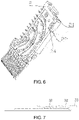
- the front end of the bent contact is a plugging end
- the bent contact comprises a plugging portion 31, a recess 32 and a mounting portion 33 which is positioned at the rear of the plugging portion and is horizontal, and the plugging portion 31, the recess 32 and the mounting portion 33 are successively arranged from front to back.
Landscapes
- Details Of Connecting Devices For Male And Female Coupling (AREA)
- Connector Housings Or Holding Contact Members (AREA)
- Coupling Device And Connection With Printed Circuit (AREA)
Claims (5)
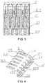
- Elektrischer Verbinder, umfassend einen Kontakt (3) mit einem vorderen Ende, das ein Steckende (30) ist, und mindestens zwei Kontaktmontageplatten (2), die links und rechts parallel angeordnet sind und sich entlang der Vorwärts- und Rückwärtsrichtung erstrecken, wobei der elektrische Verbinder ferner ein Befestigungsbiegeelement (1) zum Befestigen der Kontaktmontageplatten (2) umfasst, das Befestigungsbiegeelement (1) einen ersten Abschnitt (12) zum Befestigen an einer Oberseite des elektrischen Verbinders, einen zweiten Abschnitt (11) zum Befestigen an einem hinteren Abschnitt des elektrischen Verbinders und einen Verbindungsabschnitt (13), der den ersten und den zweiten Abschnitt verbindet, umfasst, und der erste Abschnitt (12) und der zweite Abschnitt (11) sich zur selben Seite des Verbindungsabschnitts (13) erstrecken;der Verbindungsabschnitt (13) an der Oberseite des elektrischen Verbinders vorgesehen ist, die Oberseite des elektrischen Verbinders mit einem oberen vertieften Schlitz (23) zum Einführen und Befestigen des ersten Abschnitts (12) versehen ist, so dass der erste Abschnitt (12) an der Oberseite des elektrischen Verbinders befestigt ist,wobei dadurch gekennzeichnet, dass obere Klemmblöcke (22), die in dem oberen vertieften Schlitz (23) positioniert sind, jeweils auf den verschiedenen Kontaktmontageplatten (2) angeordnet sind, der erste Abschnitt (12) mit ersten Abschnittseinführfingern (122) versehen ist, die den oberen Klemmblöcken (22) entsprechen, und erste Abschnittsschlitze (121), die die oberen Klemmblöcke (22) festklemmen, zwischen den benachbarten ersten Abschnittseinführfingern (122) gebildet sind; und Endklemmblöcke (21), die an einem hinteren Abschnitt des elektrischen Verbinders positioniert sind, jeweils auf den verschiedenen Kontaktbefestigungsplatten (2) angeordnet sind, wobei der zweite Abschnitt (11) mit Einsetzfingern (112) des zweiten Abschnitts versehen ist, die den Endklemmblöcken (21) entsprechen, und Schlitze (111) des zweiten Abschnitts, die die Endklemmblöcke (21) festklemmen, zwischen den benachbarten Einsetzfingern (112) des zweiten Abschnitts geformt sind,dadurch gekennzeichnet, dass der erste Abschnitt (12) fest auf die hintere Seitenfläche des oberen vertieften Schlitzes (23) gepresst wird und der zweite Abschnitt (11) fest auf eine Endfläche des Endabschnitts des elektrischen Verbinders gepresst wird, so dass das Befestigungsbiegeelement (1) auf den Kontaktmontageplatten (2) festgeklemmt wird.
- Elektrischer Verbinder nach Anspruch I, wobei obere Schlitze, die mit den Einsteckfingern (122) des ersten Abschnitts klemmend zusammenpassen, zwischen den benachbarten oberen Klemmblöcken geformt sind und/oder hintere Schlitze, die mit den Einsteckfingern (112) des zweiten Abschnitts klemmend zusammenpassen, zwischen den benachbarten hinteren Klemmblöcken (21) geformt sind.
- Elektrischer Steckverbinder nach Anspruch 2, wobei die ersten Einsteckfinger und die zweiten Einsteckfinger mit Höckern versehen sind, die mit den Klemmblöcken zusammenpassen.
- Elektrischer Verbinder, umfassend einen Kontakt (3) mit einem vorderen Ende, das ein Steckende (30) ist, und mindestens zwei Kontaktmontageplatten (2), die links und rechts parallel angeordnet sind und sich entlang der Vorwärts- und Rückwärtsrichtung erstrecken, wobei der elektrische Verbinder ferner ein Befestigungsbiegeelement (1) zum Befestigen der Kontaktmontageplatten (2) umfasst, das Befestigungsbiegeelement (1) einen ersten Abschnitt (12) zum Befestigen an einer Oberseite des elektrischen Verbinders, einen zweiten Abschnitt (11) zum Befestigen an einem hinteren Abschnitt des elektrischen Verbinders und einen Verbindungsabschnitt (13), der den ersten und den zweiten Abschnitt verbindet, umfasst, und der erste Abschnitt (12) und der zweite Abschnitt (11) sich zur selben Seite des Verbindungsabschnitts (13) erstrecken;dadurch gekennzeichnet, dass der Verbindungsabschnitt (13) am hinteren Abschnitt des elektrischen Verbinders vorgesehen ist, und der hintere Abschnitt des elektrischen Verbinders mit einem Endvertiefungsschlitz zum Einführen und Befestigen des zweiten Abschnitts (11) versehen ist, so dass der zweite Abschnitt (11) am hinteren Abschnitt des elektrischen Verbinders befestigt ist, wobei dadurch gekennzeichnet, dass Endklemmblöcke (21), die in dem Endvertiefungsschlitz positioniert sind, jeweils auf den verschiedenen Kontaktmontageplatten (2) angeordnet sind, der zweite Abschnitt (11) mit zweiten Abschnittseinführfingern (112) versehen ist, die den Endklemmblöcken (21) entsprechen, und zweite Abschnittsschlitze (111), die die Endklemmblöcke (21) festklemmen, zwischen den benachbarten zweiten Abschnittseinführfingern (112) gebildet sind; und obere Klemmblöcke (22), die auf der Oberseite des elektrischen Verbinders positioniert sind, jeweils auf den verschiedenen Kontaktbefestigungsplatten (2) angeordnet sind, wobei der erste Abschnitt (12) mit Einsetzfingern (122) des ersten Abschnitts versehen ist, die den oberen Klemmblöcken (22) entsprechen, und Schlitze (121) des ersten Abschnitts, die die oberen Klemmblöcke (22) festklemmen, zwischen den Einsetzfingern (122) des benachbarten ersten Abschnitts geformt sind,wobei der zweite Abschnitt fest auf die obere Seitenfläche des Endvertiefungsschlitzes gepresst wird und der erste Abschnitt (12) auf eine Endfläche der Oberseite des elektrischen Verbinders gepresst wird, so dass das Befestigungsbiegeelement (1) auf die Kontaktmontageplatten (2) geklemmt wird.
- Elektrischer Verbinder nach Anspruch 1, wobei der Kontakt (3) einen Steckabschnitt und einen Montageabschnitt umfasst, der an der Rückseite des Steckabschnitts positioniert ist, und der Montageabschnitt horizontal ist, ein nach oben gebogener Flansch an einer vorderen Spitze des Steckabschnitts angeordnet ist, ein vorderer Kontaktabschnitt, der in Kontakt mit einem adaptiven Kontakt steht, an einer unteren Seitenfläche einer Biegung des nach oben gebogenen Flansches geformt ist, eine Vertiefung, die relativ zu einem hinteren Ende des Steckabschnitts nach unten vertieft ist, zwischen dem Steckabschnitt und dem Montageabschnitt geformt ist, ein hinterer Kontaktabschnitt des Kontakts durch die Vertiefung geformt ist und der Steckabschnitt von der Verbindungsposition zwischen dem Steckabschnitt und der Vertiefung allmählich nach unten von hinten nach vorne geneigt ist.
Applications Claiming Priority (2)
| Application Number | Priority Date | Filing Date | Title |
|---|---|---|---|
| CN201610610605.1A CN106252968B (zh) | 2016-07-29 | 2016-07-29 | 电连接器 |
| PCT/CN2017/077477 WO2018018899A1 (zh) | 2016-07-29 | 2017-03-21 | 电连接器及其固定弯件 |
Publications (4)
| Publication Number | Publication Date |
|---|---|
| EP3407433A1 EP3407433A1 (de) | 2018-11-28 |
| EP3407433A4 EP3407433A4 (de) | 2019-06-26 |
| EP3407433B1 true EP3407433B1 (de) | 2022-06-29 |
| EP3407433B8 EP3407433B8 (de) | 2022-08-03 |
Family
ID=57604786
Family Applications (1)
| Application Number | Title | Priority Date | Filing Date |
|---|---|---|---|
| EP17833207.8A Active EP3407433B8 (de) | 2016-07-29 | 2017-03-21 | Elektrischer verbinder und fixierungsbiegeelement dafür |
Country Status (6)
| Country | Link |
|---|---|
| US (1) | US10608367B2 (de) |
| EP (1) | EP3407433B8 (de) |
| JP (1) | JP6781763B2 (de) |
| KR (1) | KR102153481B1 (de) |
| CN (1) | CN106252968B (de) |
| WO (1) | WO2018018899A1 (de) |
Families Citing this family (5)
| Publication number | Priority date | Publication date | Assignee | Title |
|---|---|---|---|---|
| CN106252968B (zh) | 2016-07-29 | 2019-06-07 | 中航光电科技股份有限公司 | 电连接器 |
| USD926701S1 (en) * | 2019-05-31 | 2021-08-03 | Starconn Electronic (Su Zhou) Co., Ltd | Electrical connector |
| CN110783756A (zh) * | 2019-09-23 | 2020-02-11 | 中航光电科技股份有限公司 | 一种混装印制板连接器 |
| CN111448716B (zh) * | 2020-03-05 | 2021-09-21 | 四川华丰科技股份有限公司 | 背板连接器 |
| CN112952448B (zh) * | 2021-01-28 | 2022-12-06 | 深圳市豪塑科技有限公司 | 连接器及其生产工艺 |
Citations (1)
| Publication number | Priority date | Publication date | Assignee | Title |
|---|---|---|---|---|
| US20090111298A1 (en) * | 2007-10-30 | 2009-04-30 | Fci Americas Technology, Inc. | Retention Member |
Family Cites Families (18)
| Publication number | Priority date | Publication date | Assignee | Title |
|---|---|---|---|---|
| US5993259A (en) * | 1997-02-07 | 1999-11-30 | Teradyne, Inc. | High speed, high density electrical connector |
| JP3433253B2 (ja) | 1999-11-03 | 2003-08-04 | モレックス インコーポレーテッド | コネクタ装置 |
| US6979215B2 (en) * | 2001-11-28 | 2005-12-27 | Molex Incorporated | High-density connector assembly with flexural capabilities |
| US6875031B1 (en) * | 2003-12-05 | 2005-04-05 | Hon Hai Precision Ind. Co., Ltd. | Electrical connector with circuit board module |
| US8083553B2 (en) * | 2005-06-30 | 2011-12-27 | Amphenol Corporation | Connector with improved shielding in mating contact region |
| US7497736B2 (en) * | 2006-12-19 | 2009-03-03 | Fci Americas Technology, Inc. | Shieldless, high-speed, low-cross-talk electrical connector |
| US7503804B2 (en) * | 2006-12-19 | 2009-03-17 | Fci Americas Technology Inc. | Backplane connector |
| US7637767B2 (en) * | 2008-01-04 | 2009-12-29 | Tyco Electronics Corporation | Cable connector assembly |
| CN201285845Y (zh) * | 2008-08-05 | 2009-08-05 | 富士康(昆山)电脑接插件有限公司 | 电连接器 |
| US8366485B2 (en) * | 2009-03-19 | 2013-02-05 | Fci Americas Technology Llc | Electrical connector having ribbed ground plate |
| CN202034538U (zh) * | 2011-02-26 | 2011-11-09 | 安费诺(常州)连接系统有限公司 | 波浪形端子连接器 |
| US8475209B1 (en) * | 2012-02-14 | 2013-07-02 | Tyco Electronics Corporation | Receptacle assembly |
| US8662924B2 (en) | 2012-04-23 | 2014-03-04 | Tyco Electronics Corporation | Electrical connector system having impedance control |
| US9033750B2 (en) * | 2012-08-15 | 2015-05-19 | Tyco Electronics Corporation | Electrical contact |
| CN202940374U (zh) * | 2012-11-13 | 2013-05-15 | 安费诺(常州)高端连接器有限公司 | 具有防倾斜金属支架的连接器 |
| KR20150123861A (ko) * | 2013-03-04 | 2015-11-04 | 쓰리엠 이노베이티브 프로퍼티즈 컴파니 | 전기 상호 연결 시스템 및 그에 대한 전기 커넥터 |
| CN104167620B (zh) * | 2013-08-29 | 2017-08-04 | 中航光电科技股份有限公司 | 弯式接触件及插孔模块和电连接器 |
| CN106252968B (zh) * | 2016-07-29 | 2019-06-07 | 中航光电科技股份有限公司 | 电连接器 |
-
2016
- 2016-07-29 CN CN201610610605.1A patent/CN106252968B/zh active Active
-
2017
- 2017-03-21 US US16/078,011 patent/US10608367B2/en active Active
- 2017-03-21 JP JP2018541704A patent/JP6781763B2/ja active Active
- 2017-03-21 KR KR1020187021963A patent/KR102153481B1/ko active Active
- 2017-03-21 EP EP17833207.8A patent/EP3407433B8/de active Active
- 2017-03-21 WO PCT/CN2017/077477 patent/WO2018018899A1/zh not_active Ceased
Patent Citations (1)
| Publication number | Priority date | Publication date | Assignee | Title |
|---|---|---|---|---|
| US20090111298A1 (en) * | 2007-10-30 | 2009-04-30 | Fci Americas Technology, Inc. | Retention Member |
Also Published As
| Publication number | Publication date |
|---|---|
| KR102153481B1 (ko) | 2020-09-08 |
| EP3407433A1 (de) | 2018-11-28 |
| CN106252968A (zh) | 2016-12-21 |
| CN106252968B (zh) | 2019-06-07 |
| EP3407433B8 (de) | 2022-08-03 |
| EP3407433A4 (de) | 2019-06-26 |
| JP6781763B2 (ja) | 2020-11-04 |
| JP2019505079A (ja) | 2019-02-21 |
| US10608367B2 (en) | 2020-03-31 |
| WO2018018899A1 (zh) | 2018-02-01 |
| US20190260152A1 (en) | 2019-08-22 |
| KR20180098399A (ko) | 2018-09-03 |
Similar Documents
| Publication | Publication Date | Title |
|---|---|---|
| TWI760222B (zh) | 背板連接器 | |
| JP4891305B2 (ja) | 電気コネクタ | |
| JP4885173B2 (ja) | ソケットコネクタ | |
| EP3407433B1 (de) | Elektrischer verbinder und fixierungsbiegeelement dafür | |
| JP5174859B2 (ja) | 電気コネクタ | |
| CN101640333B (zh) | 连接器 | |
| CN201638995U (zh) | 连接器 | |
| TWI427872B (zh) | 連接器 | |
| CN201207447Y (zh) | 电连接器组件 | |
| US8172620B2 (en) | Electrical connector assembly | |
| US8096815B2 (en) | Reliable electrical connection electrical connector assembly | |
| CN109038003A (zh) | 电连接器 | |
| US20110111628A1 (en) | Cable assembly and method of manufacturing the same | |
| CN101924296A (zh) | 线缆连接器组件 | |
| US8851928B2 (en) | Electrical connector | |
| CN201829692U (zh) | 电连接器 | |
| US8162679B2 (en) | Insulation displacement contact and electric connector using the same | |
| CN103579811B (zh) | 电连接器 | |
| CN205429352U (zh) | 电连接器及电连接器组合 | |
| CN202363647U (zh) | 卡缘连接器组件 | |
| CN103855535A (zh) | 具有抗拉机制的线对板连接器组件 | |
| CN110073552A (zh) | 电连接器 | |
| TWM664848U (zh) | 端子模組以及背板連接器 | |
| TWM631355U (zh) | 電連接器 | |
| TWM459585U (zh) | 連接器 |
Legal Events
| Date | Code | Title | Description |
|---|---|---|---|
| STAA | Information on the status of an ep patent application or granted ep patent |
Free format text: STATUS: THE INTERNATIONAL PUBLICATION HAS BEEN MADE |
|
| PUAI | Public reference made under article 153(3) epc to a published international application that has entered the european phase |
Free format text: ORIGINAL CODE: 0009012 |
|
| STAA | Information on the status of an ep patent application or granted ep patent |
Free format text: STATUS: REQUEST FOR EXAMINATION WAS MADE |
|
| 17P | Request for examination filed |
Effective date: 20180823 |
|
| AK | Designated contracting states |
Kind code of ref document: A1 Designated state(s): AL AT BE BG CH CY CZ DE DK EE ES FI FR GB GR HR HU IE IS IT LI LT LU LV MC MK MT NL NO PL PT RO RS SE SI SK SM TR |
|
| AX | Request for extension of the european patent |
Extension state: BA ME |
|
| A4 | Supplementary search report drawn up and despatched |
Effective date: 20190528 |
|
| RIC1 | Information provided on ipc code assigned before grant |
Ipc: H01R 13/514 20060101AFI20190522BHEP Ipc: H01R 13/518 20060101ALI20190522BHEP Ipc: H01R 12/72 20110101ALI20190522BHEP Ipc: H01R 9/24 20060101ALI20190522BHEP |
|
| DAV | Request for validation of the european patent (deleted) | ||
| DAX | Request for extension of the european patent (deleted) | ||
| STAA | Information on the status of an ep patent application or granted ep patent |
Free format text: STATUS: EXAMINATION IS IN PROGRESS |
|
| 17Q | First examination report despatched |
Effective date: 20200415 |
|
| GRAP | Despatch of communication of intention to grant a patent |
Free format text: ORIGINAL CODE: EPIDOSNIGR1 |
|
| STAA | Information on the status of an ep patent application or granted ep patent |
Free format text: STATUS: GRANT OF PATENT IS INTENDED |
|
| INTG | Intention to grant announced |
Effective date: 20220223 |
|
| RAP3 | Party data changed (applicant data changed or rights of an application transferred) |
Owner name: AVIC JONHON OPTRONIC TECHNOLOGY CO., LTD |
|
| GRAS | Grant fee paid |
Free format text: ORIGINAL CODE: EPIDOSNIGR3 |
|
| GRAA | (expected) grant |
Free format text: ORIGINAL CODE: 0009210 |
|
| STAA | Information on the status of an ep patent application or granted ep patent |
Free format text: STATUS: THE PATENT HAS BEEN GRANTED |
|
| AK | Designated contracting states |
Kind code of ref document: B1 Designated state(s): AL AT BE BG CH CY CZ DE DK EE ES FI FR GB GR HR HU IE IS IT LI LT LU LV MC MK MT NL NO PL PT RO RS SE SI SK SM TR |
|
| GRAT | Correction requested after decision to grant or after decision to maintain patent in amended form |
Free format text: ORIGINAL CODE: EPIDOSNCDEC |
|
| REG | Reference to a national code |
Ref country code: CH Ref legal event code: EP |
|
| REG | Reference to a national code |
Ref country code: AT Ref legal event code: REF Ref document number: 1501940 Country of ref document: AT Kind code of ref document: T Effective date: 20220715 Ref country code: CH Ref legal event code: PK Free format text: BERICHTIGUNG B8 |
|
| REG | Reference to a national code |
Ref country code: IE Ref legal event code: FG4D |
|
| REG | Reference to a national code |
Ref country code: DE Ref legal event code: R096 Ref document number: 602017059078 Country of ref document: DE |
|
| REG | Reference to a national code |
Ref country code: DE Ref legal event code: R081 Ref document number: 602017059078 Country of ref document: DE Owner name: AVIC JONHON OPTRONIC TECHNOLOGY CO., LTD., LUO, CN Free format text: FORMER OWNER: AVIC JONHON OPTRONIC TECHNOLOGY CO., LTD, LUOYANG, HENAN, CN |
|
| RAP4 | Party data changed (patent owner data changed or rights of a patent transferred) |
Owner name: AVIC JONHON OPTRONIC TECHNOLOGY CO., LTD. |
|
| REG | Reference to a national code |
Ref country code: LT Ref legal event code: MG9D |
|
| PG25 | Lapsed in a contracting state [announced via postgrant information from national office to epo] |
Ref country code: SE Free format text: LAPSE BECAUSE OF FAILURE TO SUBMIT A TRANSLATION OF THE DESCRIPTION OR TO PAY THE FEE WITHIN THE PRESCRIBED TIME-LIMIT Effective date: 20220629 Ref country code: NO Free format text: LAPSE BECAUSE OF FAILURE TO SUBMIT A TRANSLATION OF THE DESCRIPTION OR TO PAY THE FEE WITHIN THE PRESCRIBED TIME-LIMIT Effective date: 20220929 Ref country code: LT Free format text: LAPSE BECAUSE OF FAILURE TO SUBMIT A TRANSLATION OF THE DESCRIPTION OR TO PAY THE FEE WITHIN THE PRESCRIBED TIME-LIMIT Effective date: 20220629 Ref country code: HR Free format text: LAPSE BECAUSE OF FAILURE TO SUBMIT A TRANSLATION OF THE DESCRIPTION OR TO PAY THE FEE WITHIN THE PRESCRIBED TIME-LIMIT Effective date: 20220629 Ref country code: GR Free format text: LAPSE BECAUSE OF FAILURE TO SUBMIT A TRANSLATION OF THE DESCRIPTION OR TO PAY THE FEE WITHIN THE PRESCRIBED TIME-LIMIT Effective date: 20220930 Ref country code: FI Free format text: LAPSE BECAUSE OF FAILURE TO SUBMIT A TRANSLATION OF THE DESCRIPTION OR TO PAY THE FEE WITHIN THE PRESCRIBED TIME-LIMIT Effective date: 20220629 Ref country code: BG Free format text: LAPSE BECAUSE OF FAILURE TO SUBMIT A TRANSLATION OF THE DESCRIPTION OR TO PAY THE FEE WITHIN THE PRESCRIBED TIME-LIMIT Effective date: 20220929 |
|
| REG | Reference to a national code |
Ref country code: NL Ref legal event code: MP Effective date: 20220629 |
|
| REG | Reference to a national code |
Ref country code: AT Ref legal event code: MK05 Ref document number: 1501940 Country of ref document: AT Kind code of ref document: T Effective date: 20220629 |
|
| PG25 | Lapsed in a contracting state [announced via postgrant information from national office to epo] |
Ref country code: RS Free format text: LAPSE BECAUSE OF FAILURE TO SUBMIT A TRANSLATION OF THE DESCRIPTION OR TO PAY THE FEE WITHIN THE PRESCRIBED TIME-LIMIT Effective date: 20220629 Ref country code: LV Free format text: LAPSE BECAUSE OF FAILURE TO SUBMIT A TRANSLATION OF THE DESCRIPTION OR TO PAY THE FEE WITHIN THE PRESCRIBED TIME-LIMIT Effective date: 20220629 |
|
| PG25 | Lapsed in a contracting state [announced via postgrant information from national office to epo] |
Ref country code: NL Free format text: LAPSE BECAUSE OF FAILURE TO SUBMIT A TRANSLATION OF THE DESCRIPTION OR TO PAY THE FEE WITHIN THE PRESCRIBED TIME-LIMIT Effective date: 20220629 |
|
| PG25 | Lapsed in a contracting state [announced via postgrant information from national office to epo] |
Ref country code: SM Free format text: LAPSE BECAUSE OF FAILURE TO SUBMIT A TRANSLATION OF THE DESCRIPTION OR TO PAY THE FEE WITHIN THE PRESCRIBED TIME-LIMIT Effective date: 20220629 Ref country code: SK Free format text: LAPSE BECAUSE OF FAILURE TO SUBMIT A TRANSLATION OF THE DESCRIPTION OR TO PAY THE FEE WITHIN THE PRESCRIBED TIME-LIMIT Effective date: 20220629 Ref country code: RO Free format text: LAPSE BECAUSE OF FAILURE TO SUBMIT A TRANSLATION OF THE DESCRIPTION OR TO PAY THE FEE WITHIN THE PRESCRIBED TIME-LIMIT Effective date: 20220629 Ref country code: PT Free format text: LAPSE BECAUSE OF FAILURE TO SUBMIT A TRANSLATION OF THE DESCRIPTION OR TO PAY THE FEE WITHIN THE PRESCRIBED TIME-LIMIT Effective date: 20221031 Ref country code: ES Free format text: LAPSE BECAUSE OF FAILURE TO SUBMIT A TRANSLATION OF THE DESCRIPTION OR TO PAY THE FEE WITHIN THE PRESCRIBED TIME-LIMIT Effective date: 20220629 Ref country code: EE Free format text: LAPSE BECAUSE OF FAILURE TO SUBMIT A TRANSLATION OF THE DESCRIPTION OR TO PAY THE FEE WITHIN THE PRESCRIBED TIME-LIMIT Effective date: 20220629 Ref country code: AT Free format text: LAPSE BECAUSE OF FAILURE TO SUBMIT A TRANSLATION OF THE DESCRIPTION OR TO PAY THE FEE WITHIN THE PRESCRIBED TIME-LIMIT Effective date: 20220629 |
|
| PG25 | Lapsed in a contracting state [announced via postgrant information from national office to epo] |
Ref country code: PL Free format text: LAPSE BECAUSE OF FAILURE TO SUBMIT A TRANSLATION OF THE DESCRIPTION OR TO PAY THE FEE WITHIN THE PRESCRIBED TIME-LIMIT Effective date: 20220629 Ref country code: IS Free format text: LAPSE BECAUSE OF FAILURE TO SUBMIT A TRANSLATION OF THE DESCRIPTION OR TO PAY THE FEE WITHIN THE PRESCRIBED TIME-LIMIT Effective date: 20221029 |
|
| REG | Reference to a national code |
Ref country code: DE Ref legal event code: R097 Ref document number: 602017059078 Country of ref document: DE |
|
| PG25 | Lapsed in a contracting state [announced via postgrant information from national office to epo] |
Ref country code: AL Free format text: LAPSE BECAUSE OF FAILURE TO SUBMIT A TRANSLATION OF THE DESCRIPTION OR TO PAY THE FEE WITHIN THE PRESCRIBED TIME-LIMIT Effective date: 20220629 |
|
| PG25 | Lapsed in a contracting state [announced via postgrant information from national office to epo] |
Ref country code: DK Free format text: LAPSE BECAUSE OF FAILURE TO SUBMIT A TRANSLATION OF THE DESCRIPTION OR TO PAY THE FEE WITHIN THE PRESCRIBED TIME-LIMIT Effective date: 20220629 Ref country code: CZ Free format text: LAPSE BECAUSE OF FAILURE TO SUBMIT A TRANSLATION OF THE DESCRIPTION OR TO PAY THE FEE WITHIN THE PRESCRIBED TIME-LIMIT Effective date: 20220629 |
|
| PLBE | No opposition filed within time limit |
Free format text: ORIGINAL CODE: 0009261 |
|
| STAA | Information on the status of an ep patent application or granted ep patent |
Free format text: STATUS: NO OPPOSITION FILED WITHIN TIME LIMIT |
|
| 26N | No opposition filed |
Effective date: 20230330 |
|
| PG25 | Lapsed in a contracting state [announced via postgrant information from national office to epo] |
Ref country code: SI Free format text: LAPSE BECAUSE OF FAILURE TO SUBMIT A TRANSLATION OF THE DESCRIPTION OR TO PAY THE FEE WITHIN THE PRESCRIBED TIME-LIMIT Effective date: 20220629 |
|
| PG25 | Lapsed in a contracting state [announced via postgrant information from national office to epo] |
Ref country code: MC Free format text: LAPSE BECAUSE OF FAILURE TO SUBMIT A TRANSLATION OF THE DESCRIPTION OR TO PAY THE FEE WITHIN THE PRESCRIBED TIME-LIMIT Effective date: 20220629 |
|
| REG | Reference to a national code |
Ref country code: CH Ref legal event code: PL |
|
| REG | Reference to a national code |
Ref country code: BE Ref legal event code: MM Effective date: 20230331 |
|
| PG25 | Lapsed in a contracting state [announced via postgrant information from national office to epo] |
Ref country code: LU Free format text: LAPSE BECAUSE OF NON-PAYMENT OF DUE FEES Effective date: 20230321 |
|
| REG | Reference to a national code |
Ref country code: IE Ref legal event code: MM4A |
|
| PG25 | Lapsed in a contracting state [announced via postgrant information from national office to epo] |
Ref country code: LI Free format text: LAPSE BECAUSE OF NON-PAYMENT OF DUE FEES Effective date: 20230331 Ref country code: IT Free format text: LAPSE BECAUSE OF FAILURE TO SUBMIT A TRANSLATION OF THE DESCRIPTION OR TO PAY THE FEE WITHIN THE PRESCRIBED TIME-LIMIT Effective date: 20220629 Ref country code: IE Free format text: LAPSE BECAUSE OF NON-PAYMENT OF DUE FEES Effective date: 20230321 Ref country code: CH Free format text: LAPSE BECAUSE OF NON-PAYMENT OF DUE FEES Effective date: 20230331 |
|
| PG25 | Lapsed in a contracting state [announced via postgrant information from national office to epo] |
Ref country code: BE Free format text: LAPSE BECAUSE OF NON-PAYMENT OF DUE FEES Effective date: 20230331 |
|
| PG25 | Lapsed in a contracting state [announced via postgrant information from national office to epo] |
Ref country code: BG Free format text: LAPSE BECAUSE OF FAILURE TO SUBMIT A TRANSLATION OF THE DESCRIPTION OR TO PAY THE FEE WITHIN THE PRESCRIBED TIME-LIMIT Effective date: 20220629 |
|
| PG25 | Lapsed in a contracting state [announced via postgrant information from national office to epo] |
Ref country code: BG Free format text: LAPSE BECAUSE OF FAILURE TO SUBMIT A TRANSLATION OF THE DESCRIPTION OR TO PAY THE FEE WITHIN THE PRESCRIBED TIME-LIMIT Effective date: 20220629 |
|
| PGFP | Annual fee paid to national office [announced via postgrant information from national office to epo] |
Ref country code: DE Payment date: 20250328 Year of fee payment: 9 |
|
| PGFP | Annual fee paid to national office [announced via postgrant information from national office to epo] |
Ref country code: FR Payment date: 20250319 Year of fee payment: 9 |
|
| PGFP | Annual fee paid to national office [announced via postgrant information from national office to epo] |
Ref country code: GB Payment date: 20250317 Year of fee payment: 9 |
|
| PG25 | Lapsed in a contracting state [announced via postgrant information from national office to epo] |
Ref country code: CY Free format text: LAPSE BECAUSE OF FAILURE TO SUBMIT A TRANSLATION OF THE DESCRIPTION OR TO PAY THE FEE WITHIN THE PRESCRIBED TIME-LIMIT; INVALID AB INITIO Effective date: 20170321 |
|
| PG25 | Lapsed in a contracting state [announced via postgrant information from national office to epo] |
Ref country code: HU Free format text: LAPSE BECAUSE OF FAILURE TO SUBMIT A TRANSLATION OF THE DESCRIPTION OR TO PAY THE FEE WITHIN THE PRESCRIBED TIME-LIMIT; INVALID AB INITIO Effective date: 20170321 |
|
| PG25 | Lapsed in a contracting state [announced via postgrant information from national office to epo] |
Ref country code: TR Free format text: LAPSE BECAUSE OF FAILURE TO SUBMIT A TRANSLATION OF THE DESCRIPTION OR TO PAY THE FEE WITHIN THE PRESCRIBED TIME-LIMIT Effective date: 20220629 |