EP3405271B1 - Reinigung von mercaptanen oder thiophenen mithilfe von trennwandsäulendestillation - Google Patents
Reinigung von mercaptanen oder thiophenen mithilfe von trennwandsäulendestillation Download PDFInfo
- Publication number
- EP3405271B1 EP3405271B1 EP17741899.3A EP17741899A EP3405271B1 EP 3405271 B1 EP3405271 B1 EP 3405271B1 EP 17741899 A EP17741899 A EP 17741899A EP 3405271 B1 EP3405271 B1 EP 3405271B1
- Authority
- EP
- European Patent Office
- Prior art keywords
- section
- feed
- stream
- distillation column
- mercaptans
- Prior art date
- Legal status (The legal status is an assumption and is not a legal conclusion. Google has not performed a legal analysis and makes no representation as to the accuracy of the status listed.)
- Active
Links
- RWSOTUBLDIXVET-UHFFFAOYSA-N Dihydrogen sulfide Chemical class S RWSOTUBLDIXVET-UHFFFAOYSA-N 0.000 title claims description 65
- 238000004821 distillation Methods 0.000 title claims description 62
- 229930192474 thiophene Natural products 0.000 title claims description 28
- 150000003577 thiophenes Chemical class 0.000 title claims description 27
- 239000007788 liquid Substances 0.000 claims description 25
- 238000000034 method Methods 0.000 claims description 23
- 239000000203 mixture Substances 0.000 claims description 20
- LSDPWZHWYPCBBB-UHFFFAOYSA-N Methanethiol Chemical compound SC LSDPWZHWYPCBBB-UHFFFAOYSA-N 0.000 claims description 17
- 238000001816 cooling Methods 0.000 claims description 6
- 150000001875 compounds Chemical class 0.000 claims description 5
- OKTJSMMVPCPJKN-UHFFFAOYSA-N Carbon Chemical compound [C] OKTJSMMVPCPJKN-UHFFFAOYSA-N 0.000 claims description 4
- 229910052799 carbon Inorganic materials 0.000 claims description 4
- 239000002826 coolant Substances 0.000 claims description 4
- 239000000498 cooling water Substances 0.000 claims description 3
- 238000010438 heat treatment Methods 0.000 claims description 2
- 238000000926 separation method Methods 0.000 description 18
- 238000012856 packing Methods 0.000 description 17
- 239000000047 product Substances 0.000 description 14
- KZCOBXFFBQJQHH-UHFFFAOYSA-N octane-1-thiol Chemical class CCCCCCCCS KZCOBXFFBQJQHH-UHFFFAOYSA-N 0.000 description 12
- 238000010992 reflux Methods 0.000 description 12
- WNAHIZMDSQCWRP-UHFFFAOYSA-N dodecane-1-thiol Chemical class CCCCCCCCCCCCS WNAHIZMDSQCWRP-UHFFFAOYSA-N 0.000 description 10
- -1 cyclic mercaptans Chemical group 0.000 description 8
- 150000001336 alkenes Chemical class 0.000 description 7
- 230000000052 comparative effect Effects 0.000 description 7
- 238000006243 chemical reaction Methods 0.000 description 6
- GEKDEMKPCKTKEC-UHFFFAOYSA-N tetradecane-1-thiol Chemical compound CCCCCCCCCCCCCCS GEKDEMKPCKTKEC-UHFFFAOYSA-N 0.000 description 5
- 150000001298 alcohols Chemical class 0.000 description 4
- 230000008901 benefit Effects 0.000 description 4
- 230000015556 catabolic process Effects 0.000 description 4
- 238000004891 communication Methods 0.000 description 4
- 238000006731 degradation reaction Methods 0.000 description 4
- 239000012530 fluid Substances 0.000 description 4
- 229930195733 hydrocarbon Natural products 0.000 description 4
- 150000002430 hydrocarbons Chemical class 0.000 description 4
- 229910000037 hydrogen sulfide Inorganic materials 0.000 description 4
- 125000004122 cyclic group Chemical group 0.000 description 3
- 238000011084 recovery Methods 0.000 description 3
- 150000003568 thioethers Chemical class 0.000 description 3
- LFQSCWFLJHTTHZ-UHFFFAOYSA-N Ethanol Chemical compound CCO LFQSCWFLJHTTHZ-UHFFFAOYSA-N 0.000 description 2
- 238000009835 boiling Methods 0.000 description 2
- 239000012141 concentrate Substances 0.000 description 2
- 238000005265 energy consumption Methods 0.000 description 2
- 239000012535 impurity Substances 0.000 description 2
- 239000007791 liquid phase Substances 0.000 description 2
- 238000011068 loading method Methods 0.000 description 2
- JRZJOMJEPLMPRA-UHFFFAOYSA-N olefin Natural products CCCCCCCC=C JRZJOMJEPLMPRA-UHFFFAOYSA-N 0.000 description 2
- 238000005057 refrigeration Methods 0.000 description 2
- 239000012808 vapor phase Substances 0.000 description 2
- CRSBERNSMYQZNG-UHFFFAOYSA-N 1 -dodecene Natural products CCCCCCCCCCC=C CRSBERNSMYQZNG-UHFFFAOYSA-N 0.000 description 1
- KWKAKUADMBZCLK-UHFFFAOYSA-N 1-octene Chemical compound CCCCCCC=C KWKAKUADMBZCLK-UHFFFAOYSA-N 0.000 description 1
- SNRUBQQJIBEYMU-UHFFFAOYSA-N Dodecane Natural products CCCCCCCCCCCC SNRUBQQJIBEYMU-UHFFFAOYSA-N 0.000 description 1
- 241000183024 Populus tremula Species 0.000 description 1
- YTPLMLYBLZKORZ-UHFFFAOYSA-N Thiophene Chemical compound C=1C=CSC=1 YTPLMLYBLZKORZ-UHFFFAOYSA-N 0.000 description 1
- 238000000998 batch distillation Methods 0.000 description 1
- 239000006227 byproduct Substances 0.000 description 1
- 150000001721 carbon Chemical group 0.000 description 1
- 125000004432 carbon atom Chemical group C* 0.000 description 1
- 238000009833 condensation Methods 0.000 description 1
- 230000005494 condensation Effects 0.000 description 1
- 238000001944 continuous distillation Methods 0.000 description 1
- VTXVGVNLYGSIAR-UHFFFAOYSA-N decane-1-thiol Chemical compound CCCCCCCCCCS VTXVGVNLYGSIAR-UHFFFAOYSA-N 0.000 description 1
- 150000002019 disulfides Chemical class 0.000 description 1
- UROXMPKAGAWKPP-UHFFFAOYSA-N dodecane-2-thiol Chemical compound CCCCCCCCCCC(C)S UROXMPKAGAWKPP-UHFFFAOYSA-N 0.000 description 1
- 229940069096 dodecene Drugs 0.000 description 1
- 238000004519 manufacturing process Methods 0.000 description 1
- 239000003607 modifier Substances 0.000 description 1
- BZXFEMZFRLXGCY-UHFFFAOYSA-N octane-2-thiol Chemical compound CCCCCCC(C)S BZXFEMZFRLXGCY-UHFFFAOYSA-N 0.000 description 1
- 150000002894 organic compounds Chemical class 0.000 description 1
- 230000000704 physical effect Effects 0.000 description 1
- 229920000642 polymer Polymers 0.000 description 1
- 238000000746 purification Methods 0.000 description 1
- 239000000126 substance Substances 0.000 description 1
- 239000013589 supplement Substances 0.000 description 1
- 238000005979 thermal decomposition reaction Methods 0.000 description 1
- XLYOFNOQVPJJNP-UHFFFAOYSA-N water Substances O XLYOFNOQVPJJNP-UHFFFAOYSA-N 0.000 description 1
Images

Classifications
-
- C—CHEMISTRY; METALLURGY
- C07—ORGANIC CHEMISTRY
- C07C—ACYCLIC OR CARBOCYCLIC COMPOUNDS
- C07C319/00—Preparation of thiols, sulfides, hydropolysulfides or polysulfides
- C07C319/26—Separation; Purification; Stabilisation; Use of additives
- C07C319/28—Separation; Purification
-
- B—PERFORMING OPERATIONS; TRANSPORTING
- B01—PHYSICAL OR CHEMICAL PROCESSES OR APPARATUS IN GENERAL
- B01D—SEPARATION
- B01D3/00—Distillation or related exchange processes in which liquids are contacted with gaseous media, e.g. stripping
- B01D3/14—Fractional distillation or use of a fractionation or rectification column
- B01D3/141—Fractional distillation or use of a fractionation or rectification column where at least one distillation column contains at least one dividing wall
-
- B—PERFORMING OPERATIONS; TRANSPORTING
- B01—PHYSICAL OR CHEMICAL PROCESSES OR APPARATUS IN GENERAL
- B01D—SEPARATION
- B01D3/00—Distillation or related exchange processes in which liquids are contacted with gaseous media, e.g. stripping
- B01D3/14—Fractional distillation or use of a fractionation or rectification column
- B01D3/32—Other features of fractionating columns ; Constructional details of fractionating columns not provided for in groups B01D3/16 - B01D3/30
- B01D3/322—Reboiler specifications
-
- B—PERFORMING OPERATIONS; TRANSPORTING
- B01—PHYSICAL OR CHEMICAL PROCESSES OR APPARATUS IN GENERAL
- B01D—SEPARATION
- B01D3/00—Distillation or related exchange processes in which liquids are contacted with gaseous media, e.g. stripping
- B01D3/42—Regulation; Control
-
- B—PERFORMING OPERATIONS; TRANSPORTING
- B01—PHYSICAL OR CHEMICAL PROCESSES OR APPARATUS IN GENERAL
- B01D—SEPARATION
- B01D3/00—Distillation or related exchange processes in which liquids are contacted with gaseous media, e.g. stripping
- B01D3/42—Regulation; Control
- B01D3/4211—Regulation; Control of columns
- B01D3/4216—Head stream
-
- B—PERFORMING OPERATIONS; TRANSPORTING
- B01—PHYSICAL OR CHEMICAL PROCESSES OR APPARATUS IN GENERAL
- B01D—SEPARATION
- B01D3/00—Distillation or related exchange processes in which liquids are contacted with gaseous media, e.g. stripping
- B01D3/42—Regulation; Control
- B01D3/4211—Regulation; Control of columns
- B01D3/4261—Side stream
-
- C—CHEMISTRY; METALLURGY
- C07—ORGANIC CHEMISTRY
- C07C—ACYCLIC OR CARBOCYCLIC COMPOUNDS
- C07C319/00—Preparation of thiols, sulfides, hydropolysulfides or polysulfides
- C07C319/26—Separation; Purification; Stabilisation; Use of additives
- C07C319/28—Separation; Purification
- C07C319/30—Separation; Purification from the by-products of refining mineral oils
-
- C—CHEMISTRY; METALLURGY
- C07—ORGANIC CHEMISTRY
- C07C—ACYCLIC OR CARBOCYCLIC COMPOUNDS
- C07C321/00—Thiols, sulfides, hydropolysulfides or polysulfides
- C07C321/02—Thiols having mercapto groups bound to acyclic carbon atoms
- C07C321/04—Thiols having mercapto groups bound to acyclic carbon atoms of an acyclic saturated carbon skeleton
-
- C—CHEMISTRY; METALLURGY
- C10—PETROLEUM, GAS OR COKE INDUSTRIES; TECHNICAL GASES CONTAINING CARBON MONOXIDE; FUELS; LUBRICANTS; PEAT
- C10G—CRACKING HYDROCARBON OILS; PRODUCTION OF LIQUID HYDROCARBON MIXTURES, e.g. BY DESTRUCTIVE HYDROGENATION, OLIGOMERISATION, POLYMERISATION; RECOVERY OF HYDROCARBON OILS FROM OIL-SHALE, OIL-SAND, OR GASES; REFINING MIXTURES MAINLY CONSISTING OF HYDROCARBONS; REFORMING OF NAPHTHA; MINERAL WAXES
- C10G29/00—Refining of hydrocarbon oils, in the absence of hydrogen, with other chemicals
- C10G29/20—Organic compounds not containing metal atoms
- C10G29/28—Organic compounds not containing metal atoms containing sulfur as the only hetero atom, e.g. mercaptans, or sulfur and oxygen as the only hetero atoms
-
- C—CHEMISTRY; METALLURGY
- C10—PETROLEUM, GAS OR COKE INDUSTRIES; TECHNICAL GASES CONTAINING CARBON MONOXIDE; FUELS; LUBRICANTS; PEAT
- C10G—CRACKING HYDROCARBON OILS; PRODUCTION OF LIQUID HYDROCARBON MIXTURES, e.g. BY DESTRUCTIVE HYDROGENATION, OLIGOMERISATION, POLYMERISATION; RECOVERY OF HYDROCARBON OILS FROM OIL-SHALE, OIL-SAND, OR GASES; REFINING MIXTURES MAINLY CONSISTING OF HYDROCARBONS; REFORMING OF NAPHTHA; MINERAL WAXES
- C10G7/00—Distillation of hydrocarbon oils
Definitions
- the invention relates to a process for separating mercaptans or thiophenes from a feed stream to isolate desired compounds.
- Mercaptans and thiophenes are employed to produce various chemicals useful for industrial applications ranging from production of polymer modifiers to agricultural supplements.
- Mercaptans with a carbon length of four or greater are typically produced by reacting hydrocarbons, olefins, or alcohols with hydrogen sulfide. These reactions often produce numerous co-products with similar physical properties.
- a process for separating one or more components from a feed stream of mixed mercaptans and/or thiophenes includes providing one or more distillation columns with a feed stream containing mercaptans and/or thiophenes, the distillation column having a rectification section, a stripping section, and a feed side section separated from a side draw section by a dividing wall that extends from the rectification section to the stripping section; condensing a vapor from the distillation column with a condenser and heating a liquid from the distillation column with a reboiler; removing a distillate stream from a top region of the distillation column; removing a side drawn stream from a side region of the distillation column; and removing a bottoms stream from a bottom region of the distillation column.
- a distillation column having a divided wall is used to recover as the side draw stream a primary mercaptan with a 4 - 16 carbon length from a mixture containing its corresponding secondary and/or tertiary isomers of said primary mercaptan (with the same number of carbon atoms) and/or other more volatile sulfurous compounds such as sulfides, thiophenes, etc.) and mercaptans with at least one more carbon atom and/or less volatile sulfurous components such as sulfides, thiophenes, etc.
- a distillation column having a divided wall is preferably operated under suitable vacuum to limit the reboiler temperature to less than 240°C (e.g., to minimize thermal decomposition of the less volatile components, which can produce undesirable byproducts that co-distill with the product).
- the vacuum pressure is preferably in a range such that the overheads distillate can be condensed with conventional cooling media (e.g., water or air) without requiring chilling or refrigeration.
- a distillation column having a divided wall is preferably operated at substantially atmospheric pressure (e.g., 760 mm Hg (torr), ⁇ 20%) such that the overheads distillate can be condensed with conventional cooling media (e.g., cooling water or cooling air) without requiring a vacuum system, chilling or refrigeration, with a reboiler temperature less than 240°C.
- substantially atmospheric pressure e.g., 760 mm Hg (torr), ⁇ 20%
- conventional cooling media e.g., cooling water or cooling air
- the sections of the distillation column on either side of the dividing wall may or may not have an equal cross-sectional area and may vary along the height of the dividing wall.
- the dividing wall may be configured to accommodate the hydraulic traffic in the sections of the distillation column adjacent to the dividing wall so that each section operates in the optimal hydraulic loading range (percentage of flooding flows) and preferably so that the sections are within the same hydraulic loading range, in terms of percentage of flooding flows, thereby efficiently utilizing the column capacity.
- the distillation column uses structured packing to provide the requisite number of theoretical stages, in order to minimize the pressure drop regions and/or sections of the distillation column, to ensure that the bottoms vacuum is sufficiently deep to limit the reboiler temperature to less than 240°C, while allowing a milder vacuum in the condenser to facilitate condensation of the distillate with unchilled conventional cooling media.
- the structured packing minimizes residence time and hence the thermal exposure history, further minimizing the possibility of thermal degradation.
- the structured packing may have different specific surface areas (m 2 of contact surface / m 3 of structured packing volume) and bed length in various sections of the column to provide the requisite number of theoretical stages while balancing the pressure drops on either side of the dividing wall and maintaining the hydraulic traffic within the optimal ranges throughout the distillation column.
- the present invention relates to a process for separating feed streams containing a mixture of mercaptans or thiophenes to recover desired components. Aspects of the present invention may be particularly suited for recovering primary mercaptan, secondary mercaptan, tertiary mercaptan, cyclic mercaptan, olefins, unreacted hydrocarbons, alcohol compounds, and analogues thereof. Systems and processes of the present invention provide improved operational control of separation processes, require a reduced number of equipment, provide lower operating costs, and yield a higher concentration of desired products.
- system 100 may be employed to obtain desired components (e.g., mercaptans and/or thiophenes) from a feed stream containing mixtures of mercaptans.
- desired components e.g., mercaptans and/or thiophenes
- Suitable mixtures of mercaptans or thiophenes for separation by system 100 may be obtained from any process or reaction known by one of skill in the art including, e.g., reactions between hydrocarbons, olefins, or alcohols with hydrogen sulfide.
- mixtures of mercaptans or thiophenes are obtained from a reaction of olefin or alcohol with hydrogen sulfide, wherein during the reaction the olefin or alcohol is in stoichiometric excess relative to the hydrogen sulfide.
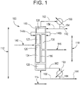
- system 100 includes a distillation column 110 in connection with a feed stream 140, a distillate stream 142, a bottoms stream 144, and a side drawn stream 146.
- System 100 further includes a condenser 150 and a reboiler 160 that are in fluid communication with column 110.
- column 110 may be configured for batch distillation.
- Column 110 includes a dividing wall 116 that extends between opposing sides of an inner surface along height 112 of column 110.
- dividing wall 116 is depicted as extending from rectification section 126 to stripping section 128 in column 110, in at least one embodiment, the dividing wall may extend through the rectification or stripping section and may connect to an inner surface of the top or bottom of the distillation column. Desirably, the composition from one side of dividing wall 116 cannot pass horizontally to the other side of dividing wall 116 and must instead travel either over or under dividing wall 116.
- Dividing wall 116 divides the central portion of column 110 into two or more sections (e.g., feed side section 120 and side draw section 130), which may have different cross-sectional areas, e.g., between 51% and 85% or between 55% and 65% of the cross-sectional area of column 110 may be allocated to one side of the dividing wall. Additionally or alternatively, dividing wall 116 may be configured such that a region above the connection with feed stream 140 has a larger cross-sectional area than a region below the connection with feed stream 140.
- the region above feed stream 140 in feed side section 120 is about 35% of the cross-sectional area of column 110, while the region above the side draw stream 146 in side draw section 130 is about 60 % of the cross-sectional area of column 110.
- Dividing wall 116 may be configured concentrically or as a flat plane. If configured concentrically, either the annular section or the central zone can function as the feed side section 120, with the area on the other side of the concentric wall serving as the side draw section 130.
- the height 118 of dividing wall 116 may depend on height 112 of column 110 or on the theoretical number of stages employed within column 100.
- dividing wall 116 may extend more than 45% and less than 80% of one or more theoretical stages of column 110.
- dividing wall 116 extends more than 55% and less than 70% of the theoretical stages of column 110 or more than 60% and less than two thirds of the theoretical stages of column 110.
- height 118 of dividing wall 116 may be between 5% and 95% of height 112 of column 110.
- height 118 of dividing wall 116 is between 35% and 80% of height 112 of column 110.
- height 118 of dividing wall 116 is between 45% and 70% of height 112 of column 110.
- Column 110 may be a tray column, a packed column, a combination of trays and packing, or may include any suitable equipment that provides contact between the liquid and vapor phases.
- Column 110 is configured to have various sections, including but not limited to a feed side section 120, a rectification section 126, a stripping section 128, and a side draw section 130.
- Each section 120, 126, 128, and/or 130 of column 110 purifies the composition therein by providing contact between the vapor and the liquid portions of the composition therein, thereby facilitating a vapor-liquid equilibrium. As the vapor portion contacts the liquid portion, the more volatile components are concentrated in the vapor portion and the less volatile components are concentrated in the liquid portion.
- the amount of contact between the vapor and liquid to achieve the desired concentrations of more volatile components in distillate stream 142 and less volatile components in bottoms stream 144 may be determined from the number of theoretical stages.
- the number of theoretical stages corresponds to a theoretical number of times the vapor portion and liquid portion should reach vapor-liquid equilibrium to achieve the desired concentrations in the distillate and bottoms.
- One of skill in the art would readily understand how to determine the number of actual trays or height of packed bedding required for section 120, 126, 128, and/or 130 of column 110 based on the descriptions herein and known correlations.
- the feed side section 120 is located in a central portion of column 110 and may extend to have a height approximately equal to the height 118 of dividing wall 116.
- Feed side section 120 contains a feed tray or distributor, adapted to receive the feed composition containing the mixture of mercaptans or thiophenes from feed stream 140.
- the feed tray or distributor may be positioned in the feed side section 120 at a location that optimizes the separation of the feed composition, such as in a middle region or in the upper half of the feed side section 120.
- the feed tray or distributor may be positioned within feed side section 120 such that between 10% and 60% of the theoretical stages in feed side section 120 are above the feed tray or distributor.
- feed side section 120 serves as a pre-fractionator that concentrates the more volatile components of feed stream 140 in the above-feed fractionator section 122 and concentrates the less volatile components in the below-feed fractionator section 124.
- Side draw section 130 is also located in a central region of column 110, but is separated from feed-side section 120 by dividing wall 116.
- Side draw section 130 contains a side draw tray or re-distributor that is in fluid communication with side draw stream 146.
- the side draw tray or re-distributor may be positioned within side draw section 130 to optimize recovery of the components in side draw stream 146, e.g., the side draw tray or re-distributor may be positioned in a middle region or lower region of side draw section 130. In one embodiment, between 40% and 90% of the theoretical stages in side draw section 130 are above the side draw tray or re-distributor.
- between 50% and 75% of the theoretical stages in side draw section 130 are above the side draw tray or re-distributor. In yet another embodiment, between 55% and 65% of the theoretical stages in side draw section 130 are above the side draw tray or re-distributor.
- Side draw section 130 may have more or fewer theoretical stages than feed side section 120. To promote the desired flow rates of vapor and liquid in sections 120 and 130, the types and/or geometry of the actual trays and/or packing may be different in sections 120 and 130. Desirably, sections 120 and 130 are configured such that each section 120 and 130 has a similar pressure profile. In one embodiment, side draw section 130 has about the same pressure profile as side draw section 130.
- Rectification section 126 is located above dividing wall 116 and receives vapor from feed side section 120 and/or side draw section 130. Rectification section 126 is in fluid communication with condenser 150 by way of streams 152, 156, and 154. The vapor leaving rectification section 126, also called the distillate, is directed towards condenser 150 by way of stream 152. Liquid distillate enters rectification section 126 by way of stream 156. Desirably, the liquid leaving rectification section 126 is controllably distributed to the feed side 120 section and side draw section 130 of column 110, e.g., by collecting the liquid at a bottom region of the rectification section 126 and distributing the liquid through streams 148a and 148b.
- a majority, e.g., 60%, 70%, 75%, 80%, 85%, 90%, 95% or more, of the liquid leaving rectification section 126 may be distributed to side draw section 130. In one embodiment, less than 20% by volume of the liquid coming from rectification section 126 enters feed side section 120. In another embodiment, less than 10% by volume of the liquid coming from rectification section 126 enters feed side section 120.
- Stripping section 128 is located below dividing wall 116 and receives liquid from feed side section 120 and/or side draw section 130. Stripping section 128 is in fluid communication with reboiler 160 by way of streams 162, 164, and 166. Liquid leaving stripping section 128, also called bottoms, is directed to reboiler 160 by way of stream 162. A portion of the bottoms, which have been heated by reboiler 160, return to stripping section 128 by way of steam 166.
- the height 112 and width 114 of column 110 may vary greatly depending on the design requirements or desired performance of system 100. For example, to achieve high levels of separation (e.g., high concentrations of the more volatile components in the distillate and high concentrations of the less volatile components in the bottoms), the number of theoretical stages may be increased and/or the amount of reflux of the distillate and/or bottoms may be increased. Increasing the number of theoretical stages, however, generally increases the cost of column 110 as increasing the number of theoretical stages generally increases height 112 of column 110. Similarly, increasing the amount of reflux generally increases the operating cost of system 100 as condenser 150 and reboiler 160 require more energy. Additionally, increasing the reflux ratio may require increasing width 114 of column 110 to accommodate the additional hydraulic traffic within column 110. Column 110 may be configured to achieve the design parameters at minimal costs by optimizing height 112 and width 114. For example, in one embodiment of column 110, the number of theoretical stages is between 1.05 - 1.25 times the minimum reflux ratio that is required to achieve the desired separation.
- Width 114 of column 110 may vary along the entire height 112 of column 110 or along sections 120, 130, 126, and/or 128 to accommodate larger volumes of hydraulic traffic therein.
- width 114 may be larger below the feed tray or distributor, e.g., width 114 below the feed tray may be between 20% and 40%, 40% and 60%, 60% and 80%, or 80% or greater than width 114 above the feed tray or distributor. In another embodiment, however, width 114 does not vary along height 112 of column 110.
- Condenser 150 may be any type of heat exchanger suitable for condensing vapors. Preferably, condenser 150 is configured to operate at or less than atmospheric pressure. In one embodiment, the vacuum pressure range is such that the coolant utilized by condenser 150 may be a conventional cooling media, e.g., cooling water, air, or the like. Condenser 150 receives distillate in the vapor phase from stream 152 and produces distillate in the liquid phase.
- the distillate reflux ratio is a ratio of the amount of distillate directed to rectification section 126 via stream 156 to the amount of distillate in distillate stream 142. Any suitable reflux ratio may be employed by system 100 such as, e.g., between 0.05 and 300, between 10 and 40, or between 0.5 and 20.
- column 110 preferably includes trays when the column 110 is operated at elevated pressures.
- Reboiler 160 may include any suitable heat exchanger configured to operate at temperatures less than 300°C. Reboiler 160 may heat the bottoms to a wide range of temperatures depending on the design parameters of system 100 including, e.g., to a temperature between 100°C and 300°C, 130°C and 270°C, 160°C and 240°C, 190°C and 240°C, etc. Preferably, reboiler 160 heats the bottoms to a temperature of 250°C or less. In one embodiment, reboiler 160 heats the bottoms to a temperature of less than 200°C.
- the operating conditions of system 100 may be adjusted depending on the composition of the feed and the desired mercaptans or thiophenes to be recovered from the feed.
- the primary mercaptans component may be removed by way of side draw stream 146, as primary mercaptans are less volatile than their corresponding secondary and tertiary isomers, which may be removed via distillate stream 142.
- the tertiary mercaptans may be removed by way of distillate stream 142, as tertiary mercaptans are more volatile than primary and secondary mercaptans, which may be removed via side draw stream 146.
- the secondary mercaptan component may be removed by way of side draw stream 146, while tertiary isomers may be removed by way of distillate stream 142 and primary mercaptan by way of bottoms stream 144, along with the less volatile components.
- the cyclic mercaptan may be removed via side draw stream 146, while more volatile and/or light co-products may be removed via distillate stream 150 and less volatile and/or heavy co-products by way of bottoms stream 144.
- system 100 is configured such that one or more compounds removed from the side drawn stream are selected from the group consisting of primary mercaptans, secondary mercaptans, tertiary mercaptans, cyclic mercaptans, olefins, unreacted hydrocarbons, and alcohol compounds.
- System 100 may recover the desired mercaptans or thiophenes in an output stream 142, 146, and/or 146, while employing less than three distillation columns 110.
- system 100 utilizes only one distillation column 110.
- system 100 reduces the required capital costs for separating compositions of mercaptans or thiophenes.
- less total energy is required than for the multi-column system.
- system 100 may be configured such that desired mercaptans or thiophenes components pass through fewer reboilers 160.
- system 100 is configured such that one or more of the components from the group consisting of primary mercaptans, secondary mercaptans, tertiary mercaptans, and cyclic mercaptans pass through only reboiler 160 prior to being recovered.
- system 100 is configured such that one or more of the components from the group consisting of primary mercaptans, secondary mercaptans, tertiary mercaptans, and cyclic mercaptans do not pass through reboiler 160 prior to being recovered.
- system 100 is configured such that two or more, e.g., three or more, of the components from the group consisting of primary mercaptans, secondary mercaptans, tertiary mercaptans, and cyclic mercaptans do not pass through reboiler 160 prior to being recovered. Additionally or alternatively, system 100 may be configured such that bottoms stream 144 contains high concentrations of less volatile components, such that the bottoms may be recovered without additional distillation processes. In one embodiment, the bottoms pass only through reboiler 160 prior to being recovered.
- system 100 advantageously enables desired mercaptan or thiophenes to be recovered with minimal degradation. For example, in one embodiment, less than 3% by mass of one or more of the components from the group consisting of primary mercaptans, secondary mercaptans, tertiary mercaptans, and cyclic mercaptans are degraded during separation within system 100. In another embodiment, less than 2% by mass of one or more of the components from the group consisting of primary mercaptans, secondary mercaptans, tertiary mercaptans, and cyclic mercaptans are degraded during separation within system 100.
- less than 1.5% by mass of one or more of the components from the group consisting of primary mercaptans, secondary mercaptans, tertiary mercaptans, and cyclic mercaptans are degraded during separation within system 100.
- less than 1.5% by mass per component of two or more, e.g., three or more, of the components from the group consisting of primary mercaptans, secondary mercaptans, tertiary mercaptans, and cyclic mercaptans are degraded during separation within system 100.
- the following examples are non-limiting embodiments of the present invention, included herein to demonstrate the advantageous results obtained from aspects of the present invention.
- the examples were generated using the Aspen Plus process simulator program to simulate and/or calculate the processes therein, including but not limited to, vapor-liquid equilibria, energy requirements, liquid and vapor traffic, pressure drop (based on built-in correlations for the various packings), cross sectional areas and/or diameters of various portions of the distillation column, and estimated percentage of flooding capacity.
- the objective is to recover n-dodecyl mercaptan (NDM), at a minimum concentration of 99.5% and containing less than 100 ppm of n-tetradecyl mercaptan (NTM), while recovering 99% of the total amount of NDM within the feed.
- the feed stream contains 89 wt% NDM, 4.9 wt% s-dodecyl mercaptan (SDM), 0.9 wt% NTM, 0.8 wt% dodecene, and 4.4 wt% components with a boiling point higher than NTM ("heavies").
- the mass flow rate of the feed stream is 1816 kg (4000 pounds) per hour.
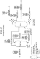
- a distillation column having a dividing wall is employed in this Example in accordance with aspects of the present invention.
- the distillation column is modeled as a pre-fractionator column (e.g., without a reboiler or condenser), representing the feed side section of the distillation column having a dividing wall, and a main distillation column having a side draw stream, which represented the dynamics occurring within the other sections of the distillation column having a dividing wall.
- the model of the distillation column employed herein is illustrated in FIG. 2 .
- the objectives are achieved by utilizing a system according to aspects of the invention.
- the system employs a distillation column with the following parameters.
- the column is specified to be 1.2 m (4 feet) in diameter and have 75 total theoretical separation stages, including a reboiler and condenser.
- the rectification section has 18 theoretical stages containing Sulzer MellapakPlus 452Y structured packing and a height equivalent to a theoretical plate (HETP) of 0.33 m (13 inches).
- the above-feed fractionator section contains 19 theoretical stages of Sulzer MellapakPlus 752Y structured packing with a HETP of 0.2 m (8 inches).
- the feed side section comprises 36% of the cross sectional area of the distillation column.
- the region of the side draw section that is above the feed stream contains 19 theoretical stages of Sulzer MellapakPlus 252Y structured packing with a HETP of 0.4 m (16 inches).
- the region below the feed stream and above the side draw stream in both of the feed side section and side draw section contains 16 theoretical stages.
- the theoretical stages utilize Sulzer MellapakPlus 252Y structured packing with a HETP of 0.4 m (16 inches).
- the feed side section comprises 42% of the distillation column's cross sectional area in this region.
- the region below the feed stream and side-draw stream in both the feed side section and the side draw section contains 15 theoretical stages.
- the theoretical stages utilize Sulzer MellapakPlus 252Y structured packing, with a HETP of 0.4 m (16 inches).
- the feed side section in this region comprises 50% of the cross sectional area of the distillation column.
- the stripping section contains 5 theoretical stages of Sulzer MellapakPlus 452Y structured packing and a HETP of 0.325 m (13 inches).
- the distillation column operates at a top vacuum (at the condenser) of 39 torr, a reflux ratio of 35.1 and a distillate condensing temperature of 121°C (250°F). 8.5% of the liquid coming from the rectification section is sent to the pre-fractionator side of the dividing wall.
- the bottoms temperature is 227°C (441°F).
- the maximum flood (%) is 71% in the stripping section.
- the required reboiler duty is 513kW/hr (1,75 million BTU/hr).
- the objective is to obtain n-octyl mercaptan (NOM) from a feed stream having a mass flow rate of 1208 kilograms per hour and containing 86.6 wt% n-octyl mercaptan (NOM), 1.1 wt% s-octyl mercaptan (SOM), 1.1 wt% n-decyl mercaptan (C10-SH), 6.8 wt% octene, 2.0 wt% of lights (e.g., more volatile than SOM) and 2.6 wt% of heavies (e.g., sulfides and disulfides).
- NOM n-octyl mercaptan
- the stream of NOM have a concentration of at least 99.0 wt% and contain less than 0.5 wt% of SOM, while recovering of 99 wt% of the NOM from the feed stream.
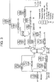
- the model of the distillation column employed herein is illustrated in FIG. 3 .
- the objectives are achieved by utilizing a system according to aspects of the invention.
- the system is modeled using methods similar to Example 1.
- the system employs a distillation column with the following parameters.
- the distillation column has a total of 45 theoretical stages, including a reboiler and condenser.
- the top rectification section has 19 theoretical stages.
- the above-feed fractionator section contains 7 theoretical stages.
- the below-feed fractionator section contains eight theoretical stages.
- the region above the side draw stream in the side draw section contains 18 theoretical stages.
- the region below the side draw stream in the side draw section contains 2 theoretical stages.
- the stripping section contains 4 theoretical stages.
- the distillation column operates at a top vacuum (at the condenser) of 80 mbar abs, a reflux ratio of 13.5, and a condensing temperature of 45°C. 15% of the liquid coming from the rectification section is sent to the feed side section.
- the bottoms temperature is 191°C.
- the required reboiler duty is 0.330 Gcal/h.
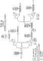
- Example 1 The same objectives as Example 1 are achieved using traditional systems for separating mercaptans and thiophenes.
- the system employs a traditional two column distillation process, where the more volatile components are removed in the first column and the n-dodecyl mercaptan is obtained from the second column, as illustrated in FIG. 4 .
- the first column has a diameter of 1.2 m (4 feet) and contains 55 theoretical stages, including a reboiler and condenser.
- the theoretical stages contain Sulzer MellapakPlus 452Y structured packing and a HETP of 0.325 m (13 inches).
- the first column operates at a top vacuum (at the condenser) of 39 torr, a reflux ratio of 33.3, and a condensing temperature of 121°C (250°F).
- the bottoms temperature is 186°C (366°F).
- the maximum flood (%) is 79%, in the region below the feed.
- the required reboiler duty is 513kW/hr (1,75 million BTU/hr).
- the second distillation column is three feet in diameter, and has 30 theoretical stages, including a reboiler and a condenser.
- the theoretical stages are designed to be Sulzer MellapakPlus 452Y structured packing, with a HETP of 0.325 m (13 inches).
- the second distillation column operates at a top vacuum (at the condenser) of 36 torr, a reflux ratio of 0.6, and the condensing temperature is 168°C (335°F). The bottoms temperature is 227°C (441°F).
- the maximum flood (%) is 72%, in the region above the feed.
- the required reboiler duty is 208kW/hr (0,71 million BTU/hr).
- the combined reboiler duties of the two columns is 721kW/hr (2,46 million BTU/hr). which is 40.6% greater than the reboiler duty of the DWC in Example 1.
- Example 2 The same objectives as Example 2 are achieved using traditional systems for separating mercaptans and thiophenes.
- the system employs a traditional two column distillation process, where the more volatile components are removed in the first column and the n-dodecyl mercaptan is obtained from the second column, as illustrated in FIG. 5 .
- the first distillation column is configured to remove the C10-SH and the less volatile components by way of the bottoms stream, and send its distillate (containing SOM, NOM and light components) as feed to the second column.
- the second distillation column recovers the NOM in the bottoms stream and removes SOM and more volatile components by way of the distillate.
- the distillation column has a diameter of 0.65 meters and 15 theoretical stages, including the reboiler and condenser.
- the theoretical stages contain Sulzer MellapakPlus 250X structured packing, with a HETP of 500 mm.
- the column operates at a top vacuum (at the condenser) of 80 mbar abs, a reflux ratio of 0.2, and the condensing temperature is 45°C.
- the bottoms temperature is 179°C.
- the maximum flood (%) is 60%, in the region below the feed.
- the required reboiler duty is 0.143 Gcal/h.
- the second distillation column has a diameter of 1.1 meters and 35 theoretical stages, including the reboiler and condenser.
- the theoretical stages contain Sulzer MellapakPlus 750Y structured packing and had a HETP of 200 mm.
- the second distillation column operates at a top vacuum (at the condenser) of 80 mbar abs and a reflux ratio of 15, and the condensing temperature is 45°C.
- the bottoms temperature is 131°C.
- the maximum flood (%) is 75%, in the region above the feed.
- the required reboiler duty is 0.278 Gcal/h.
- the combined reboiler duties of the two columns is 0.421 Gcal/h, which is 27.6% greater than the reboiler duty of the DWC in Example 2.
- Table 1 shown below, provides various operational parameters for the systems employed in Example 1 and Comparative Example 1. Notably, the system of Example 1 provides the following advantages over the system employed in Comparative Example 1:
- Example 2 provides the following advantages over the system employed in Comparative Example 2:
Landscapes
- Chemical & Material Sciences (AREA)
- Organic Chemistry (AREA)
- Chemical Kinetics & Catalysis (AREA)
- Oil, Petroleum & Natural Gas (AREA)
- Engineering & Computer Science (AREA)
- General Chemical & Material Sciences (AREA)
- Vaporization, Distillation, Condensation, Sublimation, And Cold Traps (AREA)
- Organic Low-Molecular-Weight Compounds And Preparation Thereof (AREA)
Claims (10)
- Verfahren zum Abtrennen eines primären Merkaptans mit einer Länge von 4 bis 16 Kohlenstoffatomen und gegebenenfalls Thiophenen aus einem Einspeisestrom als Seitenabzugstrom, wobei der Einspeisestrom eine Mischung ist, welche die entsprechenden sekundären und/oder tertiären Isomere des primären Merkaptans enthält, unter Verwendung einer Destillierkolonne, wobei das Verfahren umfasst:Bereitstellen des Einspeisestroms an eine oder mehrere Destillierkolonnen, wobei die Destillierkolonne einen Rektifizierabschnitt, einen Strippabschnitt und einen Einspeiseseitenabschnitt aufweist, der von einem Seitenabzugabschnitt durch eine Trennwand getrennt ist, die sich von dem Rektifizierabschnitt zu dem Strippabschnitt erstreckt;Kondensieren eines Dampfes aus der Destillierkolonne mit einem Kondensator und Erwärmen einer Flüssigkeit aus der Destillierkolonne mit einem Reboiler;Entfernen eines Destillatstroms aus einer oberen Region der Destillierkolonne;Entfernen eines Seitenabzugstroms eines primären Merkaptans mit einer Kohlenstoffkettenlänge von 4 bis 16 aus einer Seitenregion der Destillierkolonne; undEntfernen eines Sumpfproduktstroms aus einer Sumpfregion der Destillierkolonne.
- Verfahren nach Anspruch 1, wobei eine oder zwei Destillierkolonnen genutzt werden.
- Verfahren nach Anspruch 1, wobei Verbindungen, die zu dem Sumpfproduktstrom gesendet werden, nur einen Reboiler durchlaufen.
- Verfahren nach Anspruch 1, wobei der Einspeiseseitenabschnitt als Vorfraktionierer agiert.
- Verfahren nach Anspruch 1, wobei mehr als 90 % der Merkaptane einen oder mehrere Reboiler ein oder mehrere Male durchlaufen.
- Verfahren nach Anspruch 1, wobei der Reboiler bei einer Temperatur von 240 Grad Celsius oder weniger betrieben wird.
- Verfahren nach Anspruch 1, wobei der Kondensator ein Kühlmittel nutzt und das Kühlmittel ausgewählt ist aus der Gruppe bestehend aus Kühlluft und Kühlwasser.
- Verfahren nach Anspruch 1, wobei eine Flüssigkeit, die aus dem Rektifizierabschnitt kommt, kontrollierbar auf den Einspeiseseitenabschnitt und den Seitenabzugabschnitt der Destillierkolonne verteilt wird.
- Verfahren nach Anspruch 8, wobei weniger als 10 Vol.% der Flüssigkeit, die aus dem Rektifizierabschnitt kommt, in den Einspeiseseitenabschnitt eintreten.
- Verfahren nach Anspruch 1, wobei eine Höhe der Trennwand zwischen 35 % und 80 % der Höhe der Destillierkolonne liegt.
Applications Claiming Priority (2)
| Application Number | Priority Date | Filing Date | Title |
|---|---|---|---|
| US201662281798P | 2016-01-22 | 2016-01-22 | |
| PCT/US2017/014077 WO2017127508A1 (en) | 2016-01-22 | 2017-01-19 | Purificaton of mercaptans or thiophenes using dividing wall column distillation |
Publications (3)
| Publication Number | Publication Date |
|---|---|
| EP3405271A1 EP3405271A1 (de) | 2018-11-28 |
| EP3405271A4 EP3405271A4 (de) | 2019-08-21 |
| EP3405271B1 true EP3405271B1 (de) | 2022-08-31 |
Family
ID=59362731
Family Applications (1)
| Application Number | Title | Priority Date | Filing Date |
|---|---|---|---|
| EP17741899.3A Active EP3405271B1 (de) | 2016-01-22 | 2017-01-19 | Reinigung von mercaptanen oder thiophenen mithilfe von trennwandsäulendestillation |
Country Status (10)
| Country | Link |
|---|---|
| US (1) | US10807949B2 (de) |
| EP (1) | EP3405271B1 (de) |
| JP (1) | JP6942134B2 (de) |
| KR (1) | KR102216821B1 (de) |
| CN (1) | CN108601988B (de) |
| MY (1) | MY192785A (de) |
| SA (1) | SA518392047B1 (de) |
| SG (1) | SG11201805980WA (de) |
| TW (1) | TWI746500B (de) |
| WO (1) | WO2017127508A1 (de) |
Families Citing this family (6)
| Publication number | Priority date | Publication date | Assignee | Title |
|---|---|---|---|---|
| US10792585B2 (en) | 2018-03-29 | 2020-10-06 | Uop Llc | Folded fractionation column and process |
| US10792586B2 (en) | 2018-03-29 | 2020-10-06 | Uop Llc | Folded fractionation column and process |
| CN109502587B (zh) * | 2018-12-31 | 2020-07-28 | 山东新和成氨基酸有限公司 | 一种使用隔壁塔提纯二硫化碳的方法 |
| US20220401851A1 (en) * | 2019-12-05 | 2022-12-22 | Exxonmobil Research And Engineering Company | Dividing wall column separator with intensified separations |
| EP4045613A1 (de) * | 2019-12-07 | 2022-08-24 | Sulzer Management AG | Platz- und kosteneffiziente anlage und verfahren zur abtrennung eines oder mehrerer gereinigter kohlenwasserstoffströme aus rohen kohlenwasserstoffströmen, wie z.b. für die naphthastabilisierung und lpg-rückgewinnung |
| US11161810B1 (en) * | 2020-06-10 | 2021-11-02 | Arkema Inc. | Continuous photochemical production of high purity linear mercaptan and sulfide compositions |
Family Cites Families (16)
| Publication number | Priority date | Publication date | Assignee | Title |
|---|---|---|---|---|
| US3049567A (en) | 1959-06-03 | 1962-08-14 | Monsanto Chemicals | Purification of dodecyl mercaptan |
| DE1768826B1 (de) | 1968-07-04 | 1971-08-26 | Degussa | Verfahren zur Gewinnung von niederen aliphatischen Mercaptanen |
| SU825515A1 (ru) * | 1978-10-03 | 1981-04-30 | Предприятие П/Я В-8585 | Способ получения высших первичных алкилмеркаптанов 1 |
| EP0639105B1 (de) | 1992-05-08 | 1998-09-23 | SMITH, Clark Robert | Vorrichtung und verfahren für die trennung von verbindungen aus einer lösung |
| US5595634A (en) | 1995-07-10 | 1997-01-21 | Chemical Research & Licensing Company | Process for selective hydrogenation of highly unsaturated compounds and isomerization of olefins in hydrocarbon streams |
| US5755933A (en) * | 1995-07-24 | 1998-05-26 | The M. W. Kellogg Company | Partitioned distillation column |
| US6083378A (en) | 1998-09-10 | 2000-07-04 | Catalytic Distillation Technologies | Process for the simultaneous treatment and fractionation of light naphtha hydrocarbon streams |
| US6930206B1 (en) * | 2001-07-05 | 2005-08-16 | Catalytic Distillation Technologies | Process and apparatus for catalytic distillations |
| US6540907B1 (en) * | 2001-07-09 | 2003-04-01 | Uop Llc | Fractionation for full boiling range gasoline desulfurization |
| DE60214195T2 (de) * | 2002-10-22 | 2007-10-04 | Bayer Materialscience Ag | Verfahren zur Reinigung von Diisocyanatotoluol unter Verwendung einer Destillationskolonne mit Trennwand in der Endreinigung |
| FR2895417B1 (fr) | 2005-12-23 | 2011-10-14 | Inst Francais Du Petrole | Procede de desulfurisation comprenant une etape de transformation et une etape d'extraction des composes soufres |
| US8246816B2 (en) * | 2009-03-04 | 2012-08-21 | Uop Llc | Zone or system for providing one or more streams |
| US8628656B2 (en) | 2010-08-25 | 2014-01-14 | Catalytic Distillation Technologies | Hydrodesulfurization process with selected liquid recycle to reduce formation of recombinant mercaptans |
| US8562792B2 (en) * | 2010-10-28 | 2013-10-22 | Uop Llc | Vapor and liquid flow control in a dividing wall fractional distillation column |
| IN2014CN02699A (de) * | 2011-09-19 | 2015-07-03 | Kellogg Brown & Root Llc | |
| EP2946830B1 (de) * | 2013-01-16 | 2019-05-29 | LG Chem, Ltd. | Verfahren zur herstellung von alkanol |
-
2017
- 2017-01-18 TW TW106101719A patent/TWI746500B/zh active
- 2017-01-19 JP JP2018538158A patent/JP6942134B2/ja active Active
- 2017-01-19 US US16/315,689 patent/US10807949B2/en active Active
- 2017-01-19 SG SG11201805980WA patent/SG11201805980WA/en unknown
- 2017-01-19 CN CN201780007557.XA patent/CN108601988B/zh active Active
- 2017-01-19 MY MYPI2018702500A patent/MY192785A/en unknown
- 2017-01-19 KR KR1020187024263A patent/KR102216821B1/ko active IP Right Grant
- 2017-01-19 EP EP17741899.3A patent/EP3405271B1/de active Active
- 2017-01-19 WO PCT/US2017/014077 patent/WO2017127508A1/en active Application Filing
-
2018
- 2018-07-19 SA SA518392047A patent/SA518392047B1/ar unknown
Also Published As
| Publication number | Publication date |
|---|---|
| SA518392047B1 (ar) | 2021-07-05 |
| TW201731813A (zh) | 2017-09-16 |
| JP2019509259A (ja) | 2019-04-04 |
| CN108601988A (zh) | 2018-09-28 |
| SG11201805980WA (en) | 2018-08-30 |
| WO2017127508A1 (en) | 2017-07-27 |
| US10807949B2 (en) | 2020-10-20 |
| KR102216821B1 (ko) | 2021-02-19 |
| TWI746500B (zh) | 2021-11-21 |
| EP3405271A1 (de) | 2018-11-28 |
| CN108601988B (zh) | 2021-08-10 |
| EP3405271A4 (de) | 2019-08-21 |
| KR20180101588A (ko) | 2018-09-12 |
| MY192785A (en) | 2022-09-08 |
| JP6942134B2 (ja) | 2021-09-29 |
| US20190282920A1 (en) | 2019-09-19 |
Similar Documents
| Publication | Publication Date | Title |
|---|---|---|
| EP3405271B1 (de) | Reinigung von mercaptanen oder thiophenen mithilfe von trennwandsäulendestillation | |
| JP4658945B2 (ja) | エチレンアミン類を含有している混合物の蒸留による分離方法 | |
| KR101648653B1 (ko) | 아세토니트릴의 정제 방법 | |
| US6515187B1 (en) | Process for recovering acrolein or propionaldehyde from dilute aqueous streams | |
| US20100206712A1 (en) | Continuous process for preparing menthol in pure or enriched form | |
| US9902667B2 (en) | Method for reducing energy consumption in a process to purify styrene monomer | |
| US7129387B2 (en) | Low capital implementation of distributed distillation in ethylene recovery | |
| CA2876281C (en) | Process for the production of methylbutinol | |
| CN111194300B (zh) | 分隔壁蒸馏塔和通过使用该分隔壁蒸馏塔精制偏二氯乙烯的方法 | |
| CZ20004763A3 (cs) | Kaskádový ohřev kolon pro dělení ethylbenzenu a styrenu | |
| CN110776408B (zh) | 用于丙烯醛的纯化方法 | |
| WO2002022532A1 (en) | Method for separating acetone and cumene from decomposition products of cumene hydroperoxide | |
| WO2023101810A1 (en) | Simplified ethylene oxide purification methods | |
| WO2021096421A1 (en) | Method for purification of meta-phenylenediamine | |
| WO2022045960A1 (en) | Method and device for purification of p-dichlorobenzene |
Legal Events
| Date | Code | Title | Description |
|---|---|---|---|
| STAA | Information on the status of an ep patent application or granted ep patent |
Free format text: STATUS: THE INTERNATIONAL PUBLICATION HAS BEEN MADE |
|
| PUAI | Public reference made under article 153(3) epc to a published international application that has entered the european phase |
Free format text: ORIGINAL CODE: 0009012 |
|
| STAA | Information on the status of an ep patent application or granted ep patent |
Free format text: STATUS: REQUEST FOR EXAMINATION WAS MADE |
|
| 17P | Request for examination filed |
Effective date: 20180803 |
|
| AK | Designated contracting states |
Kind code of ref document: A1 Designated state(s): AL AT BE BG CH CY CZ DE DK EE ES FI FR GB GR HR HU IE IS IT LI LT LU LV MC MK MT NL NO PL PT RO RS SE SI SK SM TR |
|
| AX | Request for extension of the european patent |
Extension state: BA ME |
|
| STAA | Information on the status of an ep patent application or granted ep patent |
Free format text: STATUS: REQUEST FOR EXAMINATION WAS MADE |
|
| DAV | Request for validation of the european patent (deleted) | ||
| DAX | Request for extension of the european patent (deleted) | ||
| A4 | Supplementary search report drawn up and despatched |
Effective date: 20190719 |
|
| RIC1 | Information provided on ipc code assigned before grant |
Ipc: B01D 3/32 20060101ALI20190715BHEP Ipc: C07C 319/28 20060101ALI20190715BHEP Ipc: B01D 3/14 20060101AFI20190715BHEP Ipc: C10G 7/00 20060101ALI20190715BHEP Ipc: B01D 3/42 20060101ALI20190715BHEP Ipc: C10G 29/28 20060101ALI20190715BHEP Ipc: C10G 35/04 20060101ALI20190715BHEP |
|
| STAA | Information on the status of an ep patent application or granted ep patent |
Free format text: STATUS: EXAMINATION IS IN PROGRESS |
|
| 17Q | First examination report despatched |
Effective date: 20210527 |
|
| STAA | Information on the status of an ep patent application or granted ep patent |
Free format text: STATUS: EXAMINATION IS IN PROGRESS |
|
| GRAP | Despatch of communication of intention to grant a patent |
Free format text: ORIGINAL CODE: EPIDOSNIGR1 |
|
| STAA | Information on the status of an ep patent application or granted ep patent |
Free format text: STATUS: GRANT OF PATENT IS INTENDED |
|
| INTG | Intention to grant announced |
Effective date: 20220322 |
|
| GRAS | Grant fee paid |
Free format text: ORIGINAL CODE: EPIDOSNIGR3 |
|
| GRAA | (expected) grant |
Free format text: ORIGINAL CODE: 0009210 |
|
| STAA | Information on the status of an ep patent application or granted ep patent |
Free format text: STATUS: THE PATENT HAS BEEN GRANTED |
|
| AK | Designated contracting states |
Kind code of ref document: B1 Designated state(s): AL AT BE BG CH CY CZ DE DK EE ES FI FR GB GR HR HU IE IS IT LI LT LU LV MC MK MT NL NO PL PT RO RS SE SI SK SM TR |
|
| REG | Reference to a national code |
Ref country code: CH Ref legal event code: EP Ref country code: GB Ref legal event code: FG4D |
|
| REG | Reference to a national code |
Ref country code: AT Ref legal event code: REF Ref document number: 1514883 Country of ref document: AT Kind code of ref document: T Effective date: 20220915 Ref country code: DE Ref legal event code: R096 Ref document number: 602017061245 Country of ref document: DE |
|
| REG | Reference to a national code |
Ref country code: IE Ref legal event code: FG4D |
|
| REG | Reference to a national code |
Ref country code: NL Ref legal event code: FP |
|
| REG | Reference to a national code |
Ref country code: LT Ref legal event code: MG9D |
|
| PG25 | Lapsed in a contracting state [announced via postgrant information from national office to epo] |
Ref country code: SE Free format text: LAPSE BECAUSE OF FAILURE TO SUBMIT A TRANSLATION OF THE DESCRIPTION OR TO PAY THE FEE WITHIN THE PRESCRIBED TIME-LIMIT Effective date: 20220831 Ref country code: RS Free format text: LAPSE BECAUSE OF FAILURE TO SUBMIT A TRANSLATION OF THE DESCRIPTION OR TO PAY THE FEE WITHIN THE PRESCRIBED TIME-LIMIT Effective date: 20220831 Ref country code: NO Free format text: LAPSE BECAUSE OF FAILURE TO SUBMIT A TRANSLATION OF THE DESCRIPTION OR TO PAY THE FEE WITHIN THE PRESCRIBED TIME-LIMIT Effective date: 20221130 Ref country code: LV Free format text: LAPSE BECAUSE OF FAILURE TO SUBMIT A TRANSLATION OF THE DESCRIPTION OR TO PAY THE FEE WITHIN THE PRESCRIBED TIME-LIMIT Effective date: 20220831 Ref country code: LT Free format text: LAPSE BECAUSE OF FAILURE TO SUBMIT A TRANSLATION OF THE DESCRIPTION OR TO PAY THE FEE WITHIN THE PRESCRIBED TIME-LIMIT Effective date: 20220831 Ref country code: FI Free format text: LAPSE BECAUSE OF FAILURE TO SUBMIT A TRANSLATION OF THE DESCRIPTION OR TO PAY THE FEE WITHIN THE PRESCRIBED TIME-LIMIT Effective date: 20220831 |
|
| REG | Reference to a national code |
Ref country code: AT Ref legal event code: MK05 Ref document number: 1514883 Country of ref document: AT Kind code of ref document: T Effective date: 20220831 |
|
| PG25 | Lapsed in a contracting state [announced via postgrant information from national office to epo] |
Ref country code: PL Free format text: LAPSE BECAUSE OF FAILURE TO SUBMIT A TRANSLATION OF THE DESCRIPTION OR TO PAY THE FEE WITHIN THE PRESCRIBED TIME-LIMIT Effective date: 20220831 Ref country code: IS Free format text: LAPSE BECAUSE OF FAILURE TO SUBMIT A TRANSLATION OF THE DESCRIPTION OR TO PAY THE FEE WITHIN THE PRESCRIBED TIME-LIMIT Effective date: 20221231 Ref country code: HR Free format text: LAPSE BECAUSE OF FAILURE TO SUBMIT A TRANSLATION OF THE DESCRIPTION OR TO PAY THE FEE WITHIN THE PRESCRIBED TIME-LIMIT Effective date: 20220831 Ref country code: GR Free format text: LAPSE BECAUSE OF FAILURE TO SUBMIT A TRANSLATION OF THE DESCRIPTION OR TO PAY THE FEE WITHIN THE PRESCRIBED TIME-LIMIT Effective date: 20221201 |
|
| PG25 | Lapsed in a contracting state [announced via postgrant information from national office to epo] |
Ref country code: SM Free format text: LAPSE BECAUSE OF FAILURE TO SUBMIT A TRANSLATION OF THE DESCRIPTION OR TO PAY THE FEE WITHIN THE PRESCRIBED TIME-LIMIT Effective date: 20220831 Ref country code: RO Free format text: LAPSE BECAUSE OF FAILURE TO SUBMIT A TRANSLATION OF THE DESCRIPTION OR TO PAY THE FEE WITHIN THE PRESCRIBED TIME-LIMIT Effective date: 20220831 Ref country code: PT Free format text: LAPSE BECAUSE OF FAILURE TO SUBMIT A TRANSLATION OF THE DESCRIPTION OR TO PAY THE FEE WITHIN THE PRESCRIBED TIME-LIMIT Effective date: 20230102 Ref country code: ES Free format text: LAPSE BECAUSE OF FAILURE TO SUBMIT A TRANSLATION OF THE DESCRIPTION OR TO PAY THE FEE WITHIN THE PRESCRIBED TIME-LIMIT Effective date: 20220831 Ref country code: DK Free format text: LAPSE BECAUSE OF FAILURE TO SUBMIT A TRANSLATION OF THE DESCRIPTION OR TO PAY THE FEE WITHIN THE PRESCRIBED TIME-LIMIT Effective date: 20220831 Ref country code: CZ Free format text: LAPSE BECAUSE OF FAILURE TO SUBMIT A TRANSLATION OF THE DESCRIPTION OR TO PAY THE FEE WITHIN THE PRESCRIBED TIME-LIMIT Effective date: 20220831 Ref country code: AT Free format text: LAPSE BECAUSE OF FAILURE TO SUBMIT A TRANSLATION OF THE DESCRIPTION OR TO PAY THE FEE WITHIN THE PRESCRIBED TIME-LIMIT Effective date: 20220831 |
|
| PG25 | Lapsed in a contracting state [announced via postgrant information from national office to epo] |
Ref country code: SK Free format text: LAPSE BECAUSE OF FAILURE TO SUBMIT A TRANSLATION OF THE DESCRIPTION OR TO PAY THE FEE WITHIN THE PRESCRIBED TIME-LIMIT Effective date: 20220831 Ref country code: EE Free format text: LAPSE BECAUSE OF FAILURE TO SUBMIT A TRANSLATION OF THE DESCRIPTION OR TO PAY THE FEE WITHIN THE PRESCRIBED TIME-LIMIT Effective date: 20220831 |
|
| PGFP | Annual fee paid to national office [announced via postgrant information from national office to epo] |
Ref country code: IT Payment date: 20221213 Year of fee payment: 7 |
|
| REG | Reference to a national code |
Ref country code: DE Ref legal event code: R097 Ref document number: 602017061245 Country of ref document: DE |
|
| PG25 | Lapsed in a contracting state [announced via postgrant information from national office to epo] |
Ref country code: AL Free format text: LAPSE BECAUSE OF FAILURE TO SUBMIT A TRANSLATION OF THE DESCRIPTION OR TO PAY THE FEE WITHIN THE PRESCRIBED TIME-LIMIT Effective date: 20220831 |
|
| PLBE | No opposition filed within time limit |
Free format text: ORIGINAL CODE: 0009261 |
|
| STAA | Information on the status of an ep patent application or granted ep patent |
Free format text: STATUS: NO OPPOSITION FILED WITHIN TIME LIMIT |
|
| P01 | Opt-out of the competence of the unified patent court (upc) registered |
Effective date: 20230609 |
|
| 26N | No opposition filed |
Effective date: 20230601 |
|
| PG25 | Lapsed in a contracting state [announced via postgrant information from national office to epo] |
Ref country code: SI Free format text: LAPSE BECAUSE OF FAILURE TO SUBMIT A TRANSLATION OF THE DESCRIPTION OR TO PAY THE FEE WITHIN THE PRESCRIBED TIME-LIMIT Effective date: 20220831 |
|
| PG25 | Lapsed in a contracting state [announced via postgrant information from national office to epo] |
Ref country code: LU Free format text: LAPSE BECAUSE OF NON-PAYMENT OF DUE FEES Effective date: 20230119 |
|
| PGFP | Annual fee paid to national office [announced via postgrant information from national office to epo] |
Ref country code: GB Payment date: 20231130 Year of fee payment: 8 |
|
| PG25 | Lapsed in a contracting state [announced via postgrant information from national office to epo] |
Ref country code: IE Free format text: LAPSE BECAUSE OF NON-PAYMENT OF DUE FEES Effective date: 20230119 |
|
| PGFP | Annual fee paid to national office [announced via postgrant information from national office to epo] |
Ref country code: NL Payment date: 20231215 Year of fee payment: 8 Ref country code: FR Payment date: 20231212 Year of fee payment: 8 |
|
| PGFP | Annual fee paid to national office [announced via postgrant information from national office to epo] |
Ref country code: BE Payment date: 20231219 Year of fee payment: 8 |
|
| PGFP | Annual fee paid to national office [announced via postgrant information from national office to epo] |
Ref country code: DE Payment date: 20231205 Year of fee payment: 8 Ref country code: CH Payment date: 20240201 Year of fee payment: 8 |