EP3404494B1 - Uhrengehäuse - Google Patents
Uhrengehäuse Download PDFInfo
- Publication number
- EP3404494B1 EP3404494B1 EP17171407.4A EP17171407A EP3404494B1 EP 3404494 B1 EP3404494 B1 EP 3404494B1 EP 17171407 A EP17171407 A EP 17171407A EP 3404494 B1 EP3404494 B1 EP 3404494B1
- Authority
- EP
- European Patent Office
- Prior art keywords
- trim
- elements
- watch case
- gasket
- case
- Prior art date
- Legal status (The legal status is an assumption and is not a legal conclusion. Google has not performed a legal analysis and makes no representation as to the accuracy of the status listed.)
- Active
Links
Images


Classifications
-
- G—PHYSICS
- G04—HOROLOGY
- G04B—MECHANICALLY-DRIVEN CLOCKS OR WATCHES; MECHANICAL PARTS OF CLOCKS OR WATCHES IN GENERAL; TIME PIECES USING THE POSITION OF THE SUN, MOON OR STARS
- G04B37/00—Cases
- G04B37/08—Hermetic sealing of openings, joints, passages or slits
-
- G—PHYSICS
- G04—HOROLOGY
- G04B—MECHANICALLY-DRIVEN CLOCKS OR WATCHES; MECHANICAL PARTS OF CLOCKS OR WATCHES IN GENERAL; TIME PIECES USING THE POSITION OF THE SUN, MOON OR STARS
- G04B37/00—Cases
- G04B37/08—Hermetic sealing of openings, joints, passages or slits
- G04B37/084—Complete encasings for wrist or pocket watches without means for hermetic sealing of winding stem or crown
- G04B37/086—Complete encasings for wrist or pocket watches without means for hermetic sealing of winding stem or crown for shaped watches
Definitions
- the present invention relates to the field of watchmaking. It concerns, more particularly, a waterproof watch case.
- a conventional watch case consists of a plurality of exterior elements (case middle, back, crystal, etc.) assembled together to form a case. Each interface between two of these elements presents a potential path for the infiltration of moisture or dust, and these junctions are typically made watertight by means of simple gaskets, bonding or welding. These gaskets are typically ring-shaped, but other shapes are appropriate for non-circular watches.
- a typical construction ensures that each interface exists between two elements exclusively, in order to simplify the task of ensuring the sealing of the case.
- the use of gaskets is preferred instead of welding or gluing, since it is difficult to perform a detachment or unsoldering of such an interface without risking damage to the casing elements in question.
- This part comprises a watch case 1 of complex shape, comprising several glasses 3, 5 located on several faces of the case 1.
- each glass 3, 5 has only one interface with another component of the casing, in particular the caseband 7.
- the front glass 3 and the upper glass 5 are therefore each surrounded by a unitary element of the caseband, of which an arch-shaped part 9 is common to the two glasses 3, 5.
- a first simple seal surrounding the front glass 3 as well as a second simple seal surrounding the upper glass 5 can ensure the sealing of the box 1.
- the arch-shaped element 9 is not integral with the caseband 7, and is an added part serving as a bonding support, the sealing of the two crystals being thus ensured by glue. Disassembly of the case is thus made very difficult, and risks damaging the trim elements as mentioned above.
- the document CH500530 illustrates a timepiece comprising a more complex seal which has annular strips used to ensure sealing between two elements of the timepiece.
- the document US3706198 illustrates a gasket which not only ensures the seal between the case back and the caseband, but also serves as a support for fitting the movement into the latter.
- the document CH556567 illustrates a non-circular watch comprising a seal which is located in a peripheral groove which is provided in a rim of the back, this seal ensuring the sealing of the latter in relation to the caseband.
- the internal part of the back is not a "dressing element" within the meaning of the invention since it does not contribute to giving the part its definitive and utilitarian appearance independently of the rest of the back.
- the only path of penetration of humidity towards the interior of the case on the back side is between the main part of the back and the caseband, and there is no path of penetration from the outside between the internal part and the main part of the bottom. Consequently, and regardless of whether the bottom as a whole or exclusively its main part is considered to constitute a “dressing element”, the joint of this arrangement ensures sealing in a conventional manner between only two dressing elements.
- the aim of the invention is therefore to provide a watch case in which the aforementioned defects are at least partially overcome.
- the invention relates to a watch case as defined in the independent claim.
- This watch case comprises at least three separate casing elements, each of these casing elements being adjacent to the other two, as well as a sealing gasket arranged to ensure sealing between said casing elements.
- said sealing gasket comprises a one-piece gasket of three-dimensional shape, said gasket being adapted to ensure sealing both between said first and second covering elements, between said second and third covering elements, and between said first and third covering elements.
- said trim comprises a first part arranged to ensure sealing between the first and second covering elements, a second part arranged to ensure sealing between the first and third covering elements, and a third part arranged to ensure sealing between the second and third covering elements. Since each part of the gasket is dedicated to a particular junction between two elements, sealing is reliably ensured.
- said trim comprises at least two “T” or “Y” shaped junctions between at least three parts that said trim comprises.
- said first covering element is a first half-case
- said second covering element is a second half-case, said half-cases together forming a case.
- said third covering element is a crystal positioned on a side wall of the assembly formed by said first half-case and said second half-case.
- said third covering element may be a crown-stem assembly, said stem of which extends along an opening arranged at the interface between said half-cases. It is thus possible to arrange the stem at the junction between the half-cases, instead of having to provide a drilling in one of the latter.
- the opening in question may be defined by grooves provided in each of said half-cases.
- said gasket comprises first and second parts which have respective portions which intersect almost tangentially in the region of their junction.
- said first covering element may be a back or an upper glass (i.e. located on the dial side of the case), said second covering element may be a caseband, and said third element may be a side glass.
- the invention also relates to a timepiece comprising a watch case as defined above.
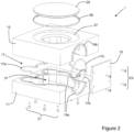
- the figures 2 And 3 schematically illustrate a watch case 1 according to the invention.
- the watch case 1 of this embodiment is formed of several exterior elements, a first 11 of which is a lower half-case, a second 13 of which is an upper half-case, and a third 15 of which is a side glass.
- these exterior elements 11, 13, 15 have been schematically represented in simple square shapes, but they can take any form according to the wishes of the manufacturer.
- the crystal 15 In its assembled state ( figure 2 ), the crystal 15 is located on a lateral face of the case 1, and therefore has an interface with each of the half-cases 11, 13. Furthermore, the half-cases 11, 13 also have an interface between them. More generically, each of said three covering elements 11, 13, 15 has a junction, and therefore an interface, with each of the other two elements. That said, it would thus be impossible to ensure the sealing of all of these three covering elements 11, 13, 15 by means of conventional gaskets, since at the locations where there is a junction that is common to all three elements 11, 13, 15 at the same time, no known simple gasket makes it possible to prevent the penetration of moisture.
- the half-cases 11, 13 can be made of opaque or transparent material, such as metal, ceramic, glass, sapphire, polymer, resin-impregnated carbon fibers, or any other suitable material.
- This gasket comprises a first part 17a dedicated to sealing between the first and second 13 trim elements 11, 13, that is to say between the two half-cases 11, 13.
- a second part 17b seals the interface between the first and third trim elements 11, 15, and a third part 17c fulfills the same function between the second and third elements 13, 15.
- the section of the illustrated gasket 17 is circular, but it could also be oval, square, rectangular, polygonal, or any other suitable shape.
- the first portion 17a of the trim 17 is located in a first plane defined by the interface between the first and second trim elements 11, 13, and said second and third parts 17b, 17c are located in a second plane making a non-zero angle with said first plane, in particular an angle of 90° in the present case.
- parts 17a, 17b, 17c of the fitting may follow curves or other complex shapes according to the desire of the manufacturer, if he wishes to give a more complex shape to the watch case 1.
- the gasket forms a “T”, which ensures the sealing of this critical point, without requiring glue.
- the seal 17 is located in corresponding grooves 19a, 19b provided for this purpose in each of the first 11 and second 13 trim elements.
- An additional groove may also be provided on the third trim element 15 if necessary, but it is not mandatory for each element 11, 13, 15 to have a groove, since a gasket housed in a groove such that it projects from the latter can cooperate with a flat surface in order to seal the junction between the elements in question.
- the half-cases 11, 13 are assembled to each other by means of a plurality of screws 21, but it is also possible to secure the half-cases 11, 13 to each other by other means.
- bayonet attachment systems may be mentioned, by screwing one of the elements onto the other, or by any other suitable means.
- the crystal 15 is also screwed onto each of the adjacent elements 11, 13 by means of screws 23.
- other attachment systems are possible, such as for example notches or grooves forming part of the two half-cases 11, 13, and which are adapted to hold the crystal 15 in position.
- the second covering element 13, i.e. the upper half-case, is provided with a housing 27 on one of its faces.
- a fourth covering element 25 which may be, for example, an additional glass, a decorative element, or the like.
- the sealing of the junction between the elements concerned is ensured by means of a conventional sealing gasket 29.
- the watch case 1 defines a housing 31 intended to house a watch movement of any type (not illustrated).
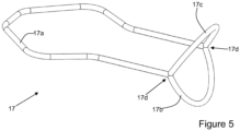
- FIG 5 illustrates a variant of a trim 17 adapted to another shape of watch case 1.
- the second and third parts 17b, 17c of the trim 17 make a non-zero angle between them, and their junctions with the first part 17a are consequently “Y” shaped.
- This shape of trim 17 is therefore adapted for a situation in which the third covering element 15 has a “V” section, the lateral faces of the first 11 and second 13 covering elements having a shape arranged to match the shape of the third covering element 15.
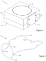
- THE figures 6 to 8 illustrate another embodiment of a watch case 1 according to the invention.
- the first covering element 11 is a transparent or opaque background of conventional shape, which is mounted in a conventional manner on the second covering element 13.
- the latter takes the form of a cylindrical caseband 13 which defines a housing 31 for a clock movement.
- the caseband can also be transparent or opaque.
- the third covering element 15 is mounted on this caseband 13 by means of screws 23.
- the latter is again a side glass 15, and a corresponding opening 33 is provided in the side wall of the caseband 13 in order to mount a dial, or to make the movement visible.
- Trim 17 (see also the figure 8 ) is formed of a first part 17a located in a groove 19c provided in the back, which ensures the seal between the back 11 and the caseband 13, as well as a second part 17b housed in a groove 19d provided in the caseband 13. This second part ensures the seal between the caseband 13 and the crystal 15.
- the first part 17a and the second part 17b are thus located in two different planes making a non-zero angle with respect to each other, the parts 17a, 17b represent two loops which intersect almost tangentially in the region of their junction 17d.
- junction 17d between these two parts 17a, 17b is located on a tangent to circles defined by each part 17a, 17b (for example circles following the halfway point of each part 17a, 17b or other circles encompassed by parts 17a, 17b and which allow the latter to merge), and in fact represents two deformed “Y”s (or a deformed “X”). It is the compression of this junction between said parts 17a, 17b which ensures the seal between the back 11, the caseband 13, and the side glass 15 at the same time.
- This arrangement allows the opening 33 to be positioned closer to the back 11 than is possible with the use of conventional gaskets.
- one possibility would be to provide a closed loop groove to accommodate a gasket providing a seal between the crystal 15 and the caseband 13.
- the groove 19c housing the gasket ensuring the seal between the back 11 and the caseband 13 must be positioned so that it does not communicate with the opening of the groove 19d.
- the gasket 17 according to the invention can seal the three cladding elements 11, 13, 15 at the same time, and allows the groove 19d of the caseband to communicate with that of the back 19c when the case 1 is in the assembled state.
- the construction of the figures 6 And 7 can be reversed, the covering element 11 being an upper glass, intended to be located on the visible side of the part when it is worn by a user.
- FIG 9 schematically illustrates yet another variant of a watch case 1 according to the invention, of which exclusively the three trim elements 11, 13, 15 as well as the fitting 17 have been shown. It should also be noted that the grooves necessary for housing the fitting 17 have not been shown here, but those illustrated in the figure 1 may be used, mutatis mutandis.
- the first 11 and second 13 trim elements are half-cases as in the variant of the figure 1 , and together form a case in assembled condition.
- the third trim element is a crown-stem assembly 15 used for reassembly and/or the control of the movement functions (not shown) the assembly 15 comprising a crown 15a and a stem 15b.
- the stem 15a enters the case formed by the set of half-cases 11, 13 at the interface between the latter, and extends along an opening defined by corresponding grooves 35a, 35b provided in each half-case 11, 13. These grooves 35a, 35b have been shown schematically.
- the first portion 17a of the gasket 17 serves to seal the interface between the two half-cases 11, 13, and the second 17b and third 17c portions serve to ensure sealing between the stem 15b and the two half-cases 11, 13.
- the opening formed between the second 17b and third 17c portions of the gasket has been exaggerated to make the passage for the stem visible.
- these portions 17b, 17c are actually shaped so that they are in intimate contact with the stem 15b, in order to seal the crown-stem assembly 15 with respect to the half-cases 11, 13. In doing so, the three trim elements 11, 13, 15 are sealed by means of a single gasket 17.
- the described embodiments may be combined in any manner that makes technical sense, by providing several additional portions of the gasket 17 in order to seal even more additional trim elements.
- the same fitting 17 may comprise a structure of quasi-tangential rings as in the embodiment of the figures 6 to 8 , as well as a structure like that of the Figures 1 to 4 , to which a structure may possibly be added according to the variant of the figure 9 .
Landscapes
- Physics & Mathematics (AREA)
- General Physics & Mathematics (AREA)
- Electric Clocks (AREA)
Claims (9)
- Uhrengehäuse (1), umfassend:- mindestens ein erstes (11), ein zweites (13) und ein drittes (15) verschiedenes Verkleidungselement, wobei jedes dieser Verkleidungselemente (11, 13, 15) an die zwei anderen angrenzt;- mindestens eine Dichtung (17), die zum Sicherstellen der Dichtheit zwischen den Verkleidungselementen (11, 13, 15) angeordnet ist;dadurch gekennzeichnet, dass die Dichtung (17) ein einteiliges Dichtungsmittel (17) von dreidimensionaler Form vorweist, wobei das Dichtungsmittel (17) zum Sicherstellen der Dichtheit gleichzeitig zwischen Folgendem angepasst ist:- dem ersten (11) und dem zweiten (13) Verkleidungselement;- dem zweiten (13) und dem dritten (15) Verkleidungselement; und- dem ersten (11) und dem dritten (15) Verkleidungselement,das Dichtungsmittel (17) umfassend einen ersten Teil (17a), der zum Sicherstellen der Dichtheit zwischen dem ersten (11) und dem zweiten (13) Verkleidungselement angeordnet ist, einen zweiten Teil (17b), der zum Sicherstellen der Dichtheit zwischen dem ersten (11) und dem dritten (15) Verkleidungselement angeordnet ist, sowie einen dritten Teil (17c), der zum Sicherstellen der Dichtheit zwischen dem zweiten (13) und dem dritten (15) Verkleidungselement angeordnet ist,wobei sich eine Verbindung zwischen dem ersten (11) und dem zweiten (13) Verkleidungselement in einer Ebene befindet, die einen Winkel ungleich null in Bezug auf eine Verbindung zwischen dem ersten (11) und dem dritten (15) Verkleidungselement aufweist,wobei das Dichtungsmittel (17) mindestens zwei Verbindungen (17d) zwischen den drei Teilen (17a, 17b, 17c) vorweist, wobei das Dichtungsmittel (17) an den Verbindungen (17d) ein "T" oder ein "Y" ausbildet.
- Uhrengehäuse (1) nach dem vorstehenden Anspruch, wobei das erste Verkleidungselement (11) ein erstes Halbmittelteil ist und das zweite Verkleidungselement (13) ein zweites Halbmittelteil ist.
- Uhrengehäuse (1) nach Anspruch 2, wobei das dritte Verkleidungselement (15) ein Glas (15) ist, das auf einer Wand der Baugruppe positioniert ist, die aus dem ersten Halbmittelteil (11) und dem zweiten Halbmittelteil (13) ausgebildet ist.
- Uhrengehäuse (1) nach Anspruch 3, wobei das Glas (15) eine Schnittstelle mit jedem der Halbmittelteile (11, 13) aufweist.
- Uhrengehäuse (1) nach Anspruch 2, wobei das dritte Verkleidungselement (15) eine Krone (15a) - Welle (15b)-Baugruppe ist, wobei sich die Welle (15b) entlang einer Öffnung erstreckt, die an der Schnittstelle zwischen den Halbmittelteilen angeordnet ist.
- Uhrengehäuse (1) nach Anspruch 5, wobei die Öffnung durch Rillen (35a, 35b) definiert ist, von denen jede in einem der Halbmittelteile (11, 13) vorgesehen ist.
- Uhrengehäuse (1) nach Anspruch 1, wobei das Dichtungsmittel (17) einen ersten Teil (17a) und einen zweiten Teil (17b) vorweist, die jeweilige Abschnitte aufweisen, die sich in der Region ihrer Verbindung im Wesentlichen tangential kreuzen.
- Uhrengehäuse (1) nach Anspruch 7, wobei das erste Verkleidungselement (11) ein Boden oder ein oberes Glas ist, das zweite Verkleidungselement (13) ein Mittelteil ist, und das dritte Element (15) ein seitliches Glas ist.
- Zeitmesser, umfassend ein Uhrengehäuse (1) nach einem der vorstehenden Ansprüche.
Priority Applications (2)
| Application Number | Priority Date | Filing Date | Title |
|---|---|---|---|
| EP17171407.4A EP3404494B1 (de) | 2017-05-16 | 2017-05-16 | Uhrengehäuse |
| PCT/EP2018/062106 WO2018210674A1 (fr) | 2017-05-16 | 2018-05-09 | Boite de montre |
Applications Claiming Priority (1)
| Application Number | Priority Date | Filing Date | Title |
|---|---|---|---|
| EP17171407.4A EP3404494B1 (de) | 2017-05-16 | 2017-05-16 | Uhrengehäuse |
Publications (2)
| Publication Number | Publication Date |
|---|---|
| EP3404494A1 EP3404494A1 (de) | 2018-11-21 |
| EP3404494B1 true EP3404494B1 (de) | 2025-02-19 |
Family
ID=58715005
Family Applications (1)
| Application Number | Title | Priority Date | Filing Date |
|---|---|---|---|
| EP17171407.4A Active EP3404494B1 (de) | 2017-05-16 | 2017-05-16 | Uhrengehäuse |
Country Status (2)
| Country | Link |
|---|---|
| EP (1) | EP3404494B1 (de) |
| WO (1) | WO2018210674A1 (de) |
Family Cites Families (4)
| Publication number | Priority date | Publication date | Assignee | Title |
|---|---|---|---|---|
| CH1558268A4 (de) * | 1968-04-18 | 1970-08-31 | ||
| GB1371224A (en) * | 1970-11-28 | 1974-10-23 | Suwa Seikosha Kk | Water-protected watch case |
| CH1711071A4 (de) * | 1971-11-23 | 1974-06-28 | ||
| CH647916GA3 (de) * | 1981-08-25 | 1985-02-28 |
-
2017
- 2017-05-16 EP EP17171407.4A patent/EP3404494B1/de active Active
-
2018
- 2018-05-09 WO PCT/EP2018/062106 patent/WO2018210674A1/fr not_active Ceased
Also Published As
| Publication number | Publication date |
|---|---|
| WO2018210674A1 (fr) | 2018-11-22 |
| EP3404494A1 (de) | 2018-11-21 |
Similar Documents
| Publication | Publication Date | Title |
|---|---|---|
| EP1662342A1 (de) | Uhr mit verwechselbarer Lunette | |
| EP2636328A1 (de) | Befestigungsvorrichtung eines Armbands an einem Armbanduhrgehäuse | |
| EP2743783B1 (de) | Zusammenbau eines Zifferblatts und eines Rohlings einer Uhr | |
| WO2008037097A2 (fr) | Boîtier de montre à carrure composite | |
| EP0873543B1 (de) | Uhrengehäuse mit einer schale und einer haltevorrichtung | |
| EP3540523B1 (de) | Armbanduhr, die ein uhrengehäuse mit zwei zifferblättern umfasst | |
| CH674292B5 (de) | ||
| EP1975747B1 (de) | Armbanduhrgehäuse | |
| EP3404494B1 (de) | Uhrengehäuse | |
| EP1102136B1 (de) | Vorrichtung zum Aufsetzen einer Schutzkappe aus hartem Material auf den Mittelteil einer Uhr | |
| CH713817A2 (fr) | Boîte de montre comprenant un joint d'étanchéité. | |
| EP0400449A1 (de) | Uhr mit einer vereinfachten Ausstattung | |
| EP3413142B1 (de) | Uhr | |
| CH702040B1 (fr) | Pièce d'horlogerie munie d'une lunette fixée à la carrure de façon amovible par un anneau élastique. | |
| EP4109181A1 (de) | Zifferblatt, armbanduhr mit einem solchen zifferblatt und verfahren zum einbau eines solchen zifferblatts in eine armbanduhr | |
| CH709421B1 (fr) | Boîte pour pièce d'horlogerie avec blindage magnétique comportant un diaphragme. | |
| EP3756904B1 (de) | Schreibinstrument, das eine kapsel umfasst, die für die aufnahme eines uhrwerks ausgelegt ist | |
| CH709079A2 (fr) | Boîte de montre. | |
| EP3346343B1 (de) | Ausstattungselement für uhr | |
| CH712378B1 (fr) | Boîte de montre à aspect visuel asymétrique | |
| EP4332690A1 (de) | Armbanduhrgehäuse für armbanduhr mit musik- oder schlagwerk, die einen boden mit deckel umfasst | |
| CH714749B1 (fr) | Montre comprenant une boîte de montre munie de deux cadrans. | |
| EP3309627B1 (de) | Armbanduhr mit indexierter scharnier | |
| CH703826B1 (fr) | Boîte de montre comportant une lunette permettant l'actionnement d'un diaphragme. | |
| EP0082840B1 (de) | Wasserdichtes uhrgehäuse |
Legal Events
| Date | Code | Title | Description |
|---|---|---|---|
| PUAI | Public reference made under article 153(3) epc to a published international application that has entered the european phase |
Free format text: ORIGINAL CODE: 0009012 |
|
| STAA | Information on the status of an ep patent application or granted ep patent |
Free format text: STATUS: THE APPLICATION HAS BEEN PUBLISHED |
|
| AK | Designated contracting states |
Kind code of ref document: A1 Designated state(s): AL AT BE BG CH CY CZ DE DK EE ES FI FR GB GR HR HU IE IS IT LI LT LU LV MC MK MT NL NO PL PT RO RS SE SI SK SM TR |
|
| AX | Request for extension of the european patent |
Extension state: BA ME |
|
| STAA | Information on the status of an ep patent application or granted ep patent |
Free format text: STATUS: REQUEST FOR EXAMINATION WAS MADE |
|
| 17P | Request for examination filed |
Effective date: 20190517 |
|
| RBV | Designated contracting states (corrected) |
Designated state(s): AL AT BE BG CH CY CZ DE DK EE ES FI FR GB GR HR HU IE IS IT LI LT LU LV MC MK MT NL NO PL PT RO RS SE SI SK SM TR |
|
| REG | Reference to a national code |
Ref country code: HK Ref legal event code: DE Ref document number: 1262446 Country of ref document: HK |
|
| STAA | Information on the status of an ep patent application or granted ep patent |
Free format text: STATUS: EXAMINATION IS IN PROGRESS |
|
| 17Q | First examination report despatched |
Effective date: 20211028 |
|
| GRAP | Despatch of communication of intention to grant a patent |
Free format text: ORIGINAL CODE: EPIDOSNIGR1 |
|
| STAA | Information on the status of an ep patent application or granted ep patent |
Free format text: STATUS: GRANT OF PATENT IS INTENDED |
|
| INTG | Intention to grant announced |
Effective date: 20231116 |
|
| GRAJ | Information related to disapproval of communication of intention to grant by the applicant or resumption of examination proceedings by the epo deleted |
Free format text: ORIGINAL CODE: EPIDOSDIGR1 |
|
| STAA | Information on the status of an ep patent application or granted ep patent |
Free format text: STATUS: EXAMINATION IS IN PROGRESS |
|
| INTC | Intention to grant announced (deleted) | ||
| GRAP | Despatch of communication of intention to grant a patent |
Free format text: ORIGINAL CODE: EPIDOSNIGR1 |
|
| STAA | Information on the status of an ep patent application or granted ep patent |
Free format text: STATUS: GRANT OF PATENT IS INTENDED |
|
| INTG | Intention to grant announced |
Effective date: 20240404 |
|
| RAP3 | Party data changed (applicant data changed or rights of an application transferred) |
Owner name: MB & F SA |
|
| GRAJ | Information related to disapproval of communication of intention to grant by the applicant or resumption of examination proceedings by the epo deleted |
Free format text: ORIGINAL CODE: EPIDOSDIGR1 |
|
| STAA | Information on the status of an ep patent application or granted ep patent |
Free format text: STATUS: EXAMINATION IS IN PROGRESS |
|
| GRAP | Despatch of communication of intention to grant a patent |
Free format text: ORIGINAL CODE: EPIDOSNIGR1 |
|
| STAA | Information on the status of an ep patent application or granted ep patent |
Free format text: STATUS: GRANT OF PATENT IS INTENDED |
|
| INTC | Intention to grant announced (deleted) | ||
| INTG | Intention to grant announced |
Effective date: 20240904 |
|
| GRAS | Grant fee paid |
Free format text: ORIGINAL CODE: EPIDOSNIGR3 |
|
| GRAA | (expected) grant |
Free format text: ORIGINAL CODE: 0009210 |
|
| STAA | Information on the status of an ep patent application or granted ep patent |
Free format text: STATUS: THE PATENT HAS BEEN GRANTED |
|
| AK | Designated contracting states |
Kind code of ref document: B1 Designated state(s): AL AT BE BG CH CY CZ DE DK EE ES FI FR GB GR HR HU IE IS IT LI LT LU LV MC MK MT NL NO PL PT RO RS SE SI SK SM TR |
|
| REG | Reference to a national code |
Ref country code: GB Ref legal event code: FG4D Free format text: NOT ENGLISH |
|
| REG | Reference to a national code |
Ref country code: CH Ref legal event code: EP |
|
| REG | Reference to a national code |
Ref country code: IE Ref legal event code: FG4D Free format text: LANGUAGE OF EP DOCUMENT: FRENCH |
|
| REG | Reference to a national code |
Ref country code: DE Ref legal event code: R096 Ref document number: 602017087822 Country of ref document: DE |
|
| REG | Reference to a national code |
Ref country code: NL Ref legal event code: MP Effective date: 20250219 |
|
| PG25 | Lapsed in a contracting state [announced via postgrant information from national office to epo] |
Ref country code: RS Free format text: LAPSE BECAUSE OF FAILURE TO SUBMIT A TRANSLATION OF THE DESCRIPTION OR TO PAY THE FEE WITHIN THE PRESCRIBED TIME-LIMIT Effective date: 20250519 |
|
| PG25 | Lapsed in a contracting state [announced via postgrant information from national office to epo] |
Ref country code: FI Free format text: LAPSE BECAUSE OF FAILURE TO SUBMIT A TRANSLATION OF THE DESCRIPTION OR TO PAY THE FEE WITHIN THE PRESCRIBED TIME-LIMIT Effective date: 20250219 |
|
| PG25 | Lapsed in a contracting state [announced via postgrant information from national office to epo] |
Ref country code: PL Free format text: LAPSE BECAUSE OF FAILURE TO SUBMIT A TRANSLATION OF THE DESCRIPTION OR TO PAY THE FEE WITHIN THE PRESCRIBED TIME-LIMIT Effective date: 20250219 |
|
| PG25 | Lapsed in a contracting state [announced via postgrant information from national office to epo] |
Ref country code: ES Free format text: LAPSE BECAUSE OF FAILURE TO SUBMIT A TRANSLATION OF THE DESCRIPTION OR TO PAY THE FEE WITHIN THE PRESCRIBED TIME-LIMIT Effective date: 20250219 |
|
| REG | Reference to a national code |
Ref country code: LT Ref legal event code: MG9D |
|
| PG25 | Lapsed in a contracting state [announced via postgrant information from national office to epo] |
Ref country code: IS Free format text: LAPSE BECAUSE OF FAILURE TO SUBMIT A TRANSLATION OF THE DESCRIPTION OR TO PAY THE FEE WITHIN THE PRESCRIBED TIME-LIMIT Effective date: 20250619 Ref country code: NO Free format text: LAPSE BECAUSE OF FAILURE TO SUBMIT A TRANSLATION OF THE DESCRIPTION OR TO PAY THE FEE WITHIN THE PRESCRIBED TIME-LIMIT Effective date: 20250519 |
|
| PG25 | Lapsed in a contracting state [announced via postgrant information from national office to epo] |
Ref country code: NL Free format text: LAPSE BECAUSE OF FAILURE TO SUBMIT A TRANSLATION OF THE DESCRIPTION OR TO PAY THE FEE WITHIN THE PRESCRIBED TIME-LIMIT Effective date: 20250219 |
|
| PG25 | Lapsed in a contracting state [announced via postgrant information from national office to epo] |
Ref country code: HR Free format text: LAPSE BECAUSE OF FAILURE TO SUBMIT A TRANSLATION OF THE DESCRIPTION OR TO PAY THE FEE WITHIN THE PRESCRIBED TIME-LIMIT Effective date: 20250219 |
|
| PG25 | Lapsed in a contracting state [announced via postgrant information from national office to epo] |
Ref country code: PT Free format text: LAPSE BECAUSE OF FAILURE TO SUBMIT A TRANSLATION OF THE DESCRIPTION OR TO PAY THE FEE WITHIN THE PRESCRIBED TIME-LIMIT Effective date: 20250620 Ref country code: LV Free format text: LAPSE BECAUSE OF FAILURE TO SUBMIT A TRANSLATION OF THE DESCRIPTION OR TO PAY THE FEE WITHIN THE PRESCRIBED TIME-LIMIT Effective date: 20250219 |
|
| PG25 | Lapsed in a contracting state [announced via postgrant information from national office to epo] |
Ref country code: GR Free format text: LAPSE BECAUSE OF FAILURE TO SUBMIT A TRANSLATION OF THE DESCRIPTION OR TO PAY THE FEE WITHIN THE PRESCRIBED TIME-LIMIT Effective date: 20250520 Ref country code: BG Free format text: LAPSE BECAUSE OF FAILURE TO SUBMIT A TRANSLATION OF THE DESCRIPTION OR TO PAY THE FEE WITHIN THE PRESCRIBED TIME-LIMIT Effective date: 20250219 |
|
| PGFP | Annual fee paid to national office [announced via postgrant information from national office to epo] |
Ref country code: CH Payment date: 20250601 Year of fee payment: 9 |
|
| REG | Reference to a national code |
Ref country code: AT Ref legal event code: MK05 Ref document number: 1768859 Country of ref document: AT Kind code of ref document: T Effective date: 20250219 |
|
| PG25 | Lapsed in a contracting state [announced via postgrant information from national office to epo] |
Ref country code: SE Free format text: LAPSE BECAUSE OF FAILURE TO SUBMIT A TRANSLATION OF THE DESCRIPTION OR TO PAY THE FEE WITHIN THE PRESCRIBED TIME-LIMIT Effective date: 20250219 |
|
| PG25 | Lapsed in a contracting state [announced via postgrant information from national office to epo] |
Ref country code: SM Free format text: LAPSE BECAUSE OF FAILURE TO SUBMIT A TRANSLATION OF THE DESCRIPTION OR TO PAY THE FEE WITHIN THE PRESCRIBED TIME-LIMIT Effective date: 20250219 |
|
| PG25 | Lapsed in a contracting state [announced via postgrant information from national office to epo] |
Ref country code: DK Free format text: LAPSE BECAUSE OF FAILURE TO SUBMIT A TRANSLATION OF THE DESCRIPTION OR TO PAY THE FEE WITHIN THE PRESCRIBED TIME-LIMIT Effective date: 20250219 |
|
| PG25 | Lapsed in a contracting state [announced via postgrant information from national office to epo] |
Ref country code: IT Free format text: LAPSE BECAUSE OF FAILURE TO SUBMIT A TRANSLATION OF THE DESCRIPTION OR TO PAY THE FEE WITHIN THE PRESCRIBED TIME-LIMIT Effective date: 20250219 |
|
| PG25 | Lapsed in a contracting state [announced via postgrant information from national office to epo] |
Ref country code: AT Free format text: LAPSE BECAUSE OF FAILURE TO SUBMIT A TRANSLATION OF THE DESCRIPTION OR TO PAY THE FEE WITHIN THE PRESCRIBED TIME-LIMIT Effective date: 20250219 |
|
| PG25 | Lapsed in a contracting state [announced via postgrant information from national office to epo] |
Ref country code: CZ Free format text: LAPSE BECAUSE OF FAILURE TO SUBMIT A TRANSLATION OF THE DESCRIPTION OR TO PAY THE FEE WITHIN THE PRESCRIBED TIME-LIMIT Effective date: 20250219 Ref country code: EE Free format text: LAPSE BECAUSE OF FAILURE TO SUBMIT A TRANSLATION OF THE DESCRIPTION OR TO PAY THE FEE WITHIN THE PRESCRIBED TIME-LIMIT Effective date: 20250219 |
|
| PG25 | Lapsed in a contracting state [announced via postgrant information from national office to epo] |
Ref country code: RO Free format text: LAPSE BECAUSE OF FAILURE TO SUBMIT A TRANSLATION OF THE DESCRIPTION OR TO PAY THE FEE WITHIN THE PRESCRIBED TIME-LIMIT Effective date: 20250219 |
|
| PG25 | Lapsed in a contracting state [announced via postgrant information from national office to epo] |
Ref country code: SK Free format text: LAPSE BECAUSE OF FAILURE TO SUBMIT A TRANSLATION OF THE DESCRIPTION OR TO PAY THE FEE WITHIN THE PRESCRIBED TIME-LIMIT Effective date: 20250219 |