EP3404152B1 - Befestigungsset zum befestigen eines montagegestells für sanitärobjekte und verwendung eines solchen befestigungssets - Google Patents
Befestigungsset zum befestigen eines montagegestells für sanitärobjekte und verwendung eines solchen befestigungssets Download PDFInfo
- Publication number
- EP3404152B1 EP3404152B1 EP18166707.2A EP18166707A EP3404152B1 EP 3404152 B1 EP3404152 B1 EP 3404152B1 EP 18166707 A EP18166707 A EP 18166707A EP 3404152 B1 EP3404152 B1 EP 3404152B1
- Authority
- EP
- European Patent Office
- Prior art keywords
- fixing
- hollow profile
- mounting frame
- fixing set
- set according
- Prior art date
- Legal status (The legal status is an assumption and is not a legal conclusion. Google has not performed a legal analysis and makes no representation as to the accuracy of the status listed.)
- Active
Links
- 238000006073 displacement reaction Methods 0.000 claims description 10
- 230000000903 blocking effect Effects 0.000 claims description 3
- 238000010276 construction Methods 0.000 claims 1
- 238000007373 indentation Methods 0.000 description 2
- 238000005253 cladding Methods 0.000 description 1
- 230000006378 damage Effects 0.000 description 1
- 230000000694 effects Effects 0.000 description 1
- 238000002347 injection Methods 0.000 description 1
- 239000007924 injection Substances 0.000 description 1
- 239000000463 material Substances 0.000 description 1
- 230000002093 peripheral effect Effects 0.000 description 1
- 230000007704 transition Effects 0.000 description 1
- 230000000007 visual effect Effects 0.000 description 1
Images


Classifications
-
- E—FIXED CONSTRUCTIONS
- E03—WATER SUPPLY; SEWERAGE
- E03D—WATER-CLOSETS OR URINALS WITH FLUSHING DEVICES; FLUSHING VALVES THEREFOR
- E03D11/00—Other component parts of water-closets, e.g. noise-reducing means in the flushing system, flushing pipes mounted in the bowl, seals for the bowl outlet, devices preventing overflow of the bowl contents; devices forming a water seal in the bowl after flushing, devices eliminating obstructions in the bowl outlet or preventing backflow of water and excrements from the waterpipe
- E03D11/13—Parts or details of bowls; Special adaptations of pipe joints or couplings for use with bowls, e.g. provisions in bowl construction preventing backflow of waste-water from the bowl in the flushing pipe or cistern, provisions for a secondary flushing, for noise-reducing
- E03D11/14—Means for connecting the bowl to the wall, e.g. to a wall outlet
- E03D11/143—Mounting frames for toilets and urinals
-
- E—FIXED CONSTRUCTIONS
- E03—WATER SUPPLY; SEWERAGE
- E03C—DOMESTIC PLUMBING INSTALLATIONS FOR FRESH WATER OR WASTE WATER; SINKS
- E03C1/00—Domestic plumbing installations for fresh water or waste water; Sinks
- E03C1/12—Plumbing installations for waste water; Basins or fountains connected thereto; Sinks
- E03C1/32—Holders or supports for basins
-
- F—MECHANICAL ENGINEERING; LIGHTING; HEATING; WEAPONS; BLASTING
- F16—ENGINEERING ELEMENTS AND UNITS; GENERAL MEASURES FOR PRODUCING AND MAINTAINING EFFECTIVE FUNCTIONING OF MACHINES OR INSTALLATIONS; THERMAL INSULATION IN GENERAL
- F16B—DEVICES FOR FASTENING OR SECURING CONSTRUCTIONAL ELEMENTS OR MACHINE PARTS TOGETHER, e.g. NAILS, BOLTS, CIRCLIPS, CLAMPS, CLIPS OR WEDGES; JOINTS OR JOINTING
- F16B37/00—Nuts or like thread-engaging members
- F16B37/08—Quickly-detachable or mountable nuts, e.g. consisting of two or more parts; Nuts movable along the bolt after tilting the nut
- F16B37/0807—Nuts engaged from the end of the bolt, e.g. axially slidable nuts
- F16B37/0814—Nuts engaged from the end of the bolt, e.g. axially slidable nuts movable along the bolt after tilting the nut
-
- F—MECHANICAL ENGINEERING; LIGHTING; HEATING; WEAPONS; BLASTING
- F16—ENGINEERING ELEMENTS AND UNITS; GENERAL MEASURES FOR PRODUCING AND MAINTAINING EFFECTIVE FUNCTIONING OF MACHINES OR INSTALLATIONS; THERMAL INSULATION IN GENERAL
- F16B—DEVICES FOR FASTENING OR SECURING CONSTRUCTIONAL ELEMENTS OR MACHINE PARTS TOGETHER, e.g. NAILS, BOLTS, CIRCLIPS, CLAMPS, CLIPS OR WEDGES; JOINTS OR JOINTING
- F16B37/00—Nuts or like thread-engaging members
- F16B37/08—Quickly-detachable or mountable nuts, e.g. consisting of two or more parts; Nuts movable along the bolt after tilting the nut
- F16B37/0807—Nuts engaged from the end of the bolt, e.g. axially slidable nuts
- F16B37/0864—Nuts engaged from the end of the bolt, e.g. axially slidable nuts with the threaded portions of the nut engaging the thread of the bolt by pressing or rotating an external retaining member such as a cap, a nut, a ring or a sleeve
Definitions
- the invention relates to a fastening set for fastening a mounting frame for sanitary objects, in particular for a cistern, a toilet bowl and / or a wash basin, to a building wall, the mounting frame being formed from hollow profile rods, with a channel-shaped connecting part which can be detachably connected to the mounting frame, which has a radially projecting connecting section, with a connecting rod which is mounted in the connecting part, with a fastening part which is attached to one end of the connecting rod and can be fastened to a building wall, and with a plug-in part.
- the fastening set called wall bracket comprises a sleeve-shaped bearing part with a radially projecting stop cam, a connecting rod in the form of a cap screw which is fastened at its head end to a mounting frame for sanitary appliances by means of the bearing part, and a fastening part which is attached and attached to the other end of the cap screw is attached to a building wall.
- the mounting frame has two vertically aligned hollow profile rods, which are C-shaped in cross section. At the upper end, two holes are machined opposite each other in the hollow profile rods, on which the sleeve-shaped bearing part is supported.
- the holes are keyhole-like and have two radial extensions which are designed such that one bearing part can be inserted with the stop cam.
- the bearing part also has a spring-elastic latching tab which snaps into the front hole of the hollow profile rod in order to secure the bearing part against falling out.
- the bearing part engages in the rear of the two holes and anchors the cap screw to the mounting frame together with the stop cam and the locking tab.
- the cap screw and the fastening part are detachably connected to one another by means of an attached bolt which is designed as a U-shaped clip nut.
- the fastening part has a shaft with a smooth passage into which the end of the cap screw facing away from the mounting frame is inserted.
- the shaft is provided with openings into which the clip nut is inserted as a bolt and is thus placed on the head screw transversely to the longitudinal axis.
- the cap screw is axially secured to the bearing part by means of a lock nut.
- the EP 2 752 526 A2 discloses a device for wall mounting a mounting frame for sanitary objects, in particular for a cistern and a toilet bowl.
- the known device comprises a wall fastening element, a positioner which can be inserted into the mounting frame, a locking element which can be displaced inside the wall fastening element, a nut screw part and a connecting rod with an external thread which extends along a mounting axis and connects the positioner to the locking element.
- the locking element has an internal motion play seat that is open along the mounting axis to allow the connecting rod to slide and is closed at opposite ends along a transverse axis perpendicular to the mounting axis to allow the locking element only a predetermined amount of movement along the cross axis.
- the object of the invention is to create a fastening set of the type mentioned at the outset, which can be produced inexpensively and offers simple and quick assembly without tools.
- the fastening set according to the invention is characterized in that the plug-in part for axially fixing the connecting part to the mounting frame can be inserted into an opening in a hollow profile rod of the mounting frame and locks the connecting part and the hollow profile rod to one another in the assembled state, the connecting section having a gap into which a section a hollow profile rod wall of the mounting frame can be introduced.
- the plug-in part which is manufactured separately in relation to the connecting part, thus has a locking function. Due to the inventive design of the plug-in part and the connecting part, the connecting part can be easily and quickly mounted on the mounting frame. At the same time, a reliable axial securing between the connecting part and the mounting frame is achieved.
- the plug-in part and the connecting part can be produced inexpensively, for example as plastic injection molded parts. No tools are required for the axial securing between the connecting part and the mounting frame, because the plug-in part, which locks the connecting part and the hollow profile rod to one another in the assembled state, can be inserted into an opening, preferably an upper, vertical opening of the hollow profile rod of the mounting frame without tools.
- an advantageous embodiment of the invention is characterized in that the plug-in part is designed as a cap or stopper which can be inserted into a vertical hollow profile rod of the mounting frame.
- the relevant opening of the hollow profile rod can thus be closed by the plug-in part.
- the plug-in part designed as a cap or stopper improves the visual impression of the assembly frame.
- the axial securing of the connecting part has a high-quality effect through the cap or the plug.
- the cap or the stopper can simultaneously serve as a design part or a logo and / or a decorative element exhibit.
- the narrow edges of the hollow profile rod, on which craftsmen can possibly injure themselves when fastening and cladding the assembly frame can be covered by the cap, so that the cap also offers protection against injuries.
- the plug-in part has a cover-like section, the upper side of which is preferably essentially flat.
- the relevant opening of the hollow profile rod can thereby be closed effectively, preferably completely, with a small amount of material, in a visually appealing manner.
- a further advantageous embodiment of the invention is characterized in that the plug-in part has a plurality of projections on the underside of the cover-like section, at least one of the projections determining the position of the plug-in part relative to the hollow profile rod in the assembled state of the fastening set, and at least another of the projections locks an axial displacement of the connecting part in the assembled state of the fastening set.
- Optimal functionality can be achieved through this design of different projections.
- this configuration can ensure that the plug-in part can be inserted into the hollow profile rod in four different positions thereof. This leads to a particularly simple and quick assembly of the plug-in part.
- a further embodiment of the invention provides that the projection defining the position of the plug-in part relative to the hollow profile rod is configured in the form of a collar.
- the collar-shaped design of the projection gives the plug-in part a high degree of stability.
- the connecting part preferably has an internally threaded section, while the connecting rod is designed as a threaded rod and can be detached by a radial displacement that is slightly greater than the internal thread depth the internal thread section can be connected or disengaged from the internal thread section. Furthermore, the connecting part preferably has a channel-shaped section, in which the connecting rod or threaded rod is guided so as to be axially displaceable, and a channel-shaped section which adjoins the channel-shaped section.
- the connecting part is provided with a bolt designed as a slide, which can be displaced axially to the longitudinal axis of the connecting rod from a non-contact position into a contact position and vice versa on the connecting part, the slide (bolt) having a contact section facing the connecting rod, which in the Contact position rests on the external thread of the connecting rod (threaded rod), so that the external thread of the connecting rod engages with the internal part thread in the contact position.
- a bolt designed as a slide, which can be displaced axially to the longitudinal axis of the connecting rod from a non-contact position into a contact position and vice versa on the connecting part, the slide (bolt) having a contact section facing the connecting rod, which in the Contact position rests on the external thread of the connecting rod (threaded rod), so that the external thread of the connecting rod engages with the internal part thread in the contact position.
- a further advantageous embodiment of the invention is characterized in that the projection blocking an axial displacement of the connecting part is formed from a plurality of webs which delimit a cross-shaped passage. This in turn ensures that the plug-in part can be inserted into the hollow profile rod in four different positions thereof, the passage being able to receive a section of the connecting rod and thus for adjusting the mounting depth of the mounting frame. In this way, the maximum adjustment range of the mounting depth of the mounting frame can be considerably increased for a given length of the connecting rod or if the mounting set is space-saving.
- the webs of the web part delimiting the cross-shaped passage preferably each have an L-shaped or angular cross-sectional profile. As a result, the webs have a high degree of flexural rigidity and a high level of stability.
- the connecting section has a gap into which a section of a hollow profile rod wall of the assembly frame can be inserted. This creates an additional positive connection between the connecting part and the Hollow profile rod of the mounting frame, so that there is a particularly reliable axial locking of the connecting part on the mounting frame.
- the gap is preferably defined by two flanges formed on the connecting section.
- the flange which is arranged within the hollow profile rod in the assembled state of the fastening set, is circular or essentially circular.
- the other flange, namely the flange, which is arranged outside the hollow profile rod in the assembled state of the fastening set, on the other hand is preferably non-circular, particularly preferably essentially oval.
- a quick and reliable axial securing of the connecting part on the hollow profile rod of the assembly frame is obtained according to a further preferred embodiment of the invention, according to which the circular or essentially circular flange has an outside diameter that is larger than a radial outside dimension of the non-circular or essentially oval Flange.
- the non-circular or essentially oval flange preferably has a further radial outer dimension that is larger than the outer diameter of the circular or substantially circular flange.
- the teaching of the present invention includes in particular the use of the fastening set according to the invention, preferably in one of the aforementioned configurations, for fastening a mounting frame for sanitary objects, for example for a cistern, a toilet bowl and / or a wash basin, on a building wall.
- the mounting set shown in the drawing is used to support and attach a mounting frame for sanitary items such as a cistern, a toilet bowl and / or a sink on a building wall. or on a carrier.
- sanitary items such as a cistern, a toilet bowl and / or a sink on a building wall. or on a carrier.
- the mounting frame usually has at least two vertically aligned hollow profile rods 2, which are connected to one another by one or more cross members (cross struts).
- the hollow profile rods 2 can consist, for example, of square tubes or of open profile rods which are essentially C-shaped in cross section. Furthermore, the hollow profile rods 2 can have longitudinal grooves 2.1, 2.2 formed on at least two of their adjacent longitudinal edges, which are used for the positive connection of a connector for fastening one or more further hollow profile rods.
- the fastening set is composed of a fastening part 3 to be fastened to a building wall, a channel-shaped connecting part 5 which can be releasably connected to the mounting frame, a connecting rod 4 which is mounted in the connecting part 5, and a plug-in part 7.
- the plug-in part 7 is used for the axial fixing of the connecting part 5 on the mounting frame in an opening 2.6 of a hollow profile rod 2 of the mounting frame in a form-fitting manner.
- the plug-in part 7 fixes and locks the connecting part 5 and the hollow profile rod 2 to one another in the assembled state.
- the connecting rod 4 is designed as a bolt or rod-shaped screw element. It can also be referred to as a threaded rod and has an external thread 4.1 at least over a length section.
- the connecting part 5 has a radially projecting connecting section 5.1, by means of which it can be positively connected to the assembly frame.
- the connecting section 5.1 is designed in such a way that the connecting part 5 can be axially fixed to the mounting frame by means of the plug-in part 7.
- the connecting section 5.1 has a gap 5.2 into which a section of the assembly frame, namely a section of the hollow profile rod 2 delimiting the through opening 2.4, can be introduced.
- the gap 5.2 is defined by two flanges 5.3, 5.4 formed on the channel-shaped connecting part.
- the flange 5.3 arranged at the front end of the channel-shaped connecting part 5 is preferably circular.
- the axially spaced flange 5.4 is oval.
- the gap 5.2 or axial distance between the two flanges 5.3, 5.4 corresponds to the wall thickness or is slightly larger than the wall thickness of the hollow profile rod 2.
- the two through openings 2.3, 2.4 of the hollow profile rod 2 are also designed differently.
- the opening 2.3, which is incorporated in the hollow profile rod side facing the room, is preferably designed as a circular hole, while the other opening 2.4, which is incorporated in the hollow profile rod side facing the building wall, is designed as an oval hole.
- the smallest inner width of the oval hole 2.4 is significantly smaller than the diameter of the other opening 2.3 and also significantly smaller than the outer diameter of the circular flange 5.3 of the channel-shaped connecting part.
- the through openings 2.3, 2.4 are dimensioned such that the connecting part 5 can be inserted into the oval opening 2.4 through the circular opening 2.3 until the circular flange 5.3 strikes the inside of the wall 2.5 of the hollow profile rod 2 having the oval opening 2.4 ( see. Figures 8 and 9 ).
- the oval Flange 5.4 is passed through oval hole 2.4 and is then on the outside of wall 2.5.
- the plug-in part 7 is inserted from above into the hollow profile rod 2 in order to axially fix the connecting part 5 on the assembly frame.
- the plug-in part 7 is preferably designed as a plug or cap in order to close the upper end opening 2.6 of the hollow profile rod 2.
- the plug-in part 7, which can also be referred to as a closure cap, has a cover-like section 7.1, the upper side of which is preferably essentially flat.
- webs or projections 7.2, 7.3 which can be inserted into the hollow profile rod 2 are formed.
- One of these projections is designed, for example, in the form of a circumferential collar 7.2, which has four side sections which are arranged essentially at right angles to one another, the respective side section having a concave indentation 7.21.
- the circular flange 5.3 of the connecting part 5 partially engages in one of these indentations 7.21.
- the side sections of the collar-shaped projection 7.2 run near or close to the inside of the hollow profile rod 2 in the assembled state of the closure cap 7 (cf. Figures 2 and 4 ).
- the other projections 7.3 of the cap 7 are designed in the form of webs which are arranged within the collar 7.2.
- the webs 7.3 project significantly deeper into the hollow profile rod 2 than the collar-shaped projection 7.2.
- the webs (projections) 7.3 each have an essentially L-shaped or angular cross-sectional profile. They delimit a cross-shaped passage (cf. Fig. 9 ), the connecting rod (threaded rod) 4 in the assembled state of the fastening set coaxial to one of the intersecting axes of the passage 8.
- the fastening part 3 to be attached to a building wall has a threaded hole 3.1 into which the connecting rod 4 designed as a threaded rod can be screwed.
- the fastening part 3 has a plate-shaped section 3.2 with a through opening 3.3 for attaching a fastening screw (not shown), the head of the screw preferably being in contact with a washer on the inside of the fastening part 3 in the assembled state.
- the passage opening 3.3 is preferably designed as an elongated hole.
- the fastening part 3 has webs 3.4 projecting from the plate-shaped section.
- the webs 3.4 enclose a screw dome 3.5 having the threaded hole 3.1 for screwing in the threaded rod 4 or are molded onto the screw dome 3.5.
- the end of the screw dome 3.5 facing the mounting frame and the edges of the webs 3.4 facing the mounting frame are preferably essentially flush with one another.
- the connecting rod (threaded rod) 4 is guided axially displaceably in the channel-shaped connecting part 5.
- the connecting part 5 has a sleeve-shaped section 5.5, which is axially followed by a channel-shaped section 5.6.
- the flanges 5.3, 5.4 are arranged on the sleeve-shaped section 5.5.
- the connecting part 5 has an oval inner cross-sectional area along its sleeve-shaped section 5.5.
- the inside of the sleeve-shaped section 5.5 is preferably smooth or essentially smooth.
- the smallest inner width of the oval inner cross-sectional area of the sleeve-shaped section 5.5 is slightly larger than the outer diameter of the thread 4.1 of the connecting rod 4.
- the groove-shaped section 5.6 of the connecting part 5 has a groove-shaped inner part thread 5.7 on the inside (cf. Fig. 5 , 7 and 9 ).
- the inner part thread 5.7 is designed to match the outer thread 4.1 of the connecting rod 4.
- the connecting rod (threaded rod) 4 fastened to the fastening part 3 By means of a certain radial displacement or a slight lowering of the connecting part 5, which is axially fixed on the mounting frame, in relation to the connecting rod (threaded rod) 4 fastened to the fastening part 3, the channel-shaped inner part thread 5.7 of the connecting part and the External thread 4.1 of the connecting rod is disengaged and the connecting part 5 is then axially displaced along the connecting rod 4.
- the said radial displacement and the axial displacement are in Fig. 5 indicated by a small vertical arrow P or a double arrow D.
- the bolt 6 designed as a slide sits on the channel-shaped connecting part 5. It can be displaced axially to the longitudinal axis of the connecting part 5 from a non-contact position into a contact position and vice versa and has a contact section 6.1 facing the connecting rod (threaded rod) 4, which in the contact position on the external thread 4.1 of the connecting rod.
- the contact section 6.1 of the bolt is designed as a projection.
- the longitudinal opening 5.61 of the trough-shaped section 5.6 of the connecting part defines an axial guide for the bolt 6, the contact section 6.1 of the bolt being received in the locking position in the longitudinal opening 5.61.
- the channel-shaped connecting part 5 has on its outside two radial shoulders 5.8, 5.9, which are arranged on opposite peripheral sections of the connecting part 5 and are axially spaced apart. Both paragraphs 5.8, 5.9 each have a sliding edge or sliding surface 5.81, 5.91 running obliquely to the longitudinal axis of the connecting part 5. The two sliding edges or sliding surfaces 5.81, 5.91 are formed at mutually facing ends of the two paragraphs 5.8, 5.9.
- a sliding edge or sliding surface 5.10 running obliquely to the longitudinal axis of the connecting part 5 is formed.
- the bolt 6 has a sliding edge or sliding surface 6.8 assigned to the sliding edges or sliding surfaces 5.81, 5.10, which also extends obliquely to the longitudinal axis of the bolt 6 or the connecting part 5.
- the channel-shaped connecting part 5 has on its outside axially spaced depressions 5.11, 5.12, to which a locking element 6.2 connected to the bolt 6 is assigned.
- the locking element 6.2 is, for example, in the form of a spring-elastic locking tab. It engages in two different positions of the bolt 6 relative to the connecting part 5 in one of the two depressions 5.11, 5.12.
- the depressions 5.11, 5.12 are assigned on the one hand to an unlocked state and on the other hand to a locked state.
- the possible directions of movement of the bolt 6 are marked by impressed or printed double arrows 6.3.
- the bolt 6 is provided with two symbols 6.4, 6.5, which symbolize a closed and an open padlock and, in combination with the double arrows 6.3, indicate the direction of displacement for setting the unlocked state or the locked state.
- the bolt 6 has on its outer surface two oppositely arranged rib surfaces 6.6, 6.7, which, as anti-slip grip surfaces, facilitate the manual, tool-free displacement of the bolt 6.
- the bolt 6 forms a (two-part) nut together with the channel-shaped connecting part 5.
- the bolt 6 can be rotated together with the connecting part 5 about the longitudinal axis of the screw element 4 and thus the mounting depth of the mounting frame can be fine-tuned.
- the latch 6 is pushed into the unlocking position and the engagement of the internal part thread 5.7 of the connecting part 5 in the external thread 4.1 of the screw element 4 is released by a radial movement of the connecting part 5.
- the connecting rod (threaded rod) 4 and the channel-shaped connecting part 5 can then be axially displaced relative to one another and the mounting depth of the mounting frame can thus be set quickly and roughly.
Landscapes
- Engineering & Computer Science (AREA)
- General Engineering & Computer Science (AREA)
- Health & Medical Sciences (AREA)
- Life Sciences & Earth Sciences (AREA)
- Hydrology & Water Resources (AREA)
- Public Health (AREA)
- Water Supply & Treatment (AREA)
- Mechanical Engineering (AREA)
- Environmental & Geological Engineering (AREA)
- Mutual Connection Of Rods And Tubes (AREA)
Description
- Die Erfindung betrifft ein Befestigungsset zum Befestigen eines Montagegestells für Sanitärobjekte, insbesondere für einen Spülkasten, eine WC-Schüssel und/oder ein Waschbecken, an einer Gebäudewand, wobei das Montagegestell aus Hohlprofilstangen gebildet ist, mit einem mit dem Montagegestell lösbar verbindbaren, kanalförmigen Verbindungsteil, das einen radial vorstehenden Verbindungsabschnitt aufweist, mit einer Verbindungsstange, die in dem Verbindungsteil gelagert ist, mit einem an einem Ende der Verbindungsstange angebrachten Befestigungsteil, das an einer Gebäudewand befestigbar ist, und mit einem Steckteil.
- Ein derartiges Befestigungsset ist aus der
EP 1 260 639 B1 bekannt. Das als Wandhalterung bezeichnete Befestigungsset umfasst ein hülsenförmiges Lagerteil mit einem radial vorstehenden Anschlagnocken, eine Verbindungsstange in Form einer Kopfschraube, die an ihrem Kopfende mittels des Lagerteils an einem Montagegestell für Sanitärapparate befestigt wird, und ein Befestigungsteil, das am anderen Ende der Kopfschraube angebracht und an einer Gebäudewand befestigt wird. Das Montagegestell weist zwei vertikal auszurichtende Hohlprofilstangen auf, die im Querschnitt C-förmig sind. Jeweils am oberen Ende sind in die Hohlprofilstangen gegenüberliegend zwei Löcher eingearbeitet, an denen das hülsenförmige Lagerteil abgestützt ist. Die Löcher sind hierzu schlüssellochartig ausgebildet und weisen zwei radiale Erweiterungen auf, die so ausgebildet sind, dass jeweils ein Lagerteil mit dem Anschlagnocken einsetzbar ist. Das Lagerteil weist zudem einen federelastischen Rastlappen auf, der an dem frontseitigen Loch der Hohlprofilstange einrastet, um das Lagerteil gegen Herausfallen zu sichern. Im eingesetzten Zustand greift das Lagerteil in das hintere der beiden Löcher ein und verankert dabei zusammen mit dem Anschlagnocken und dem Rastlappen die Kopfschraube am Montagegestell. Die Kopfschraube und das Befestigungsteil sind mittels eines aufgesteckten Riegels, der als U-förmige Clipmutter ausgebildet ist, lösbar miteinander verbunden. Das Befestigungsteil weist einen Schaft mit einem glatten Durchgang auf, in den das dem Montagegestell abgewandte Ende der Kopfschraube eingesteckt wird. Der Schaft ist mit Öffnungen versehen, in welche die Clipmutter als Riegel eingesteckt und damit quer zur Längsachse der Kopfschraube auf dieselbe aufgesteckt wird. Die Axialsicherung der Kopfschraube an dem Lagerteil erfolgt mittels einer Kontermutter. Diese bekannte Wandhalterung ermöglicht eine schnelle Montage des Montagegestells mit einer Grobeinstellung der Montagetiefe und einer nachfolgenden Feinjustierung. Allerdings ist der maximale Einstellbereich dieser Wandhalterung begrenzt. Ferner erscheint diese Wandhalterung hinsichtlich einer einfachen, für den Anwender leicht verständlichen Handhabung verbesserbar. - Die
EP 2 752 526 A2 offenbart eine Vorrichtung zur Wandmontage eines Montagegestells für Sanitärobjekte, insbesondere für einen Spülkasten und eine WC-Schüssel. Die bekannte Vorrichtung umfasst ein Wandbefestigungselement, einen Positionierer, der in das Montagegestell einsetzbar ist, ein Verriegelungselement, das im Inneren des Wandbefestigungselements verschiebbar ist, ein Mutternschraubenteil und eine Verbindungsstange mit Außengewinde, die sich entlang einer Montageachse erstreckt und den Positionierer mit dem Verriegelungselement verbindet. Das Verriegelungselement weist einen inneren Bewegungsspielsitz auf, der entlang der Montageachse offen ist, um ein Gleiten der Verbindungsstange zu ermöglichen, und an gegenüberliegenden Enden entlang einer Querachse senkrecht zur Montageachse geschlossen ist, um dem Verriegelungselement nur einen vorgegebenen Bewegungsbetrag entlang der Querachse zu ermöglichen. - Davon ausgehend liegt der Erfindung die Aufgabe zugrunde, ein Befestigungsset der eingangs genannten Art zu schaffen, das kostengünstig herstellbar ist und ohne Werkzeug eine einfache und schnelle Montage bietet.
- Gelöst wird diese Aufgabe durch ein Befestigungsset mit den im Anspruch 1 angegebenen Merkmalen. Bevorzugte und vorteilhafte Ausgestaltungen des erfindungsgemäßen Befestigungssets sind in den Unteransprüchen angegeben.
- Das erfindungsgemäße Befestigungsset ist dadurch gekennzeichnet, dass das Steckteil zur axialen Festlegung des Verbindungsteils an dem Montagegestell in eine Öffnung einer Hohlprofilstange des Montagegestells einsetzbar ist und im montierten Zustand das Verbindungsteil und die Hohlprofilstange zueinander sperrt, wobei der Verbindungsabschnitt einen Spalt aufweist, in den ein Abschnitt einer Hohlprofilstangenwand des Montagegestells einbringbar ist. Das in Bezug auf das Verbindungsteil separat gefertigte Steckteil hat somit eine Verriegelungsfunktion. Durch die erfindungsgemäße Ausführung des Steckteils sowie des Verbindungsteils lässt sich das Verbindungsteil einfach und schnell an dem Montagegestell montieren. Zugleich wird eine zuverlässige Axialsicherung zwischen dem Verbindungsteil und dem Montagegestell erzielt. Das Steckteil und das Verbindungsteil lassen sich hierzu kostengünstig herstellen, beispielsweise als Kunststoff-Spritzgießteile. Für die Axialsicherung zwischen dem Verbindungsteil und dem Montagegestell wird kein Werkzeug benötigt, denn das Steckteil, welches im montierten Zustand das Verbindungsteil und die Hohlprofilstange zueinander sperrt, lässt sich ohne Werkzeug in eine Öffnung, vorzugsweise eine obere, vertikale Öffnung der Hohlprofilstange des Montagegestells einsetzen.
- Eine vorteilhafte Ausgestaltung der Erfindung ist dadurch gekennzeichnet, dass das Steckteil als Kappe oder Stopfen ausgebildet ist, die bzw. der in eine vertikale Hohlprofilstange des Montagegestells einsteckbar ist. Die betreffende Öffnung der Hohlprofilstange lässt sich somit durch das Steckteil verschließen. Durch das als Kappe oder Stopfen ausgeführte Steckteil lässt sich der optische Eindruck des Montagegestells verbessern. Die Axialsicherung des Verbindungsteils wirkt durch die Kappe bzw. den Stopfen hochwertig. Die Kappe oder der Stopfen können dabei gleichzeitig als Designteil dienen bzw. ein Logo und/oder ein dekoratives Element aufweisen. Ferner lassen sich die schmalen Kanten der Hohlprofilstange, an denen sich Handwerker bei der Befestigung und der Verkleidung des Montagegestells eventuell verletzen können, durch die Kappe abdecken, so dass die Kappe auch einen Schutz gegen Verletzungen bietet.
- Nach einer weiteren Ausgestaltung weist das Steckteil einen deckelartigen Abschnitt auf, dessen Oberseite vorzugsweise im Wesentlichen eben ausgebildet ist. Die betreffende Öffnung der Hohlprofilstange lässt sich dadurch mit geringem Materialeinsatz wirksam, vorzugsweise vollständig, in optisch ansprechender Weise verschließen.
- Eine weitere vorteilhafte Ausgestaltung der Erfindung ist dadurch gekennzeichnet, dass das Steckteil an der Unterseite des deckelartigen Abschnitts mehrere Vorsprünge aufweist, wobei mindestens einer der Vorsprünge im montierten Zustand des Befestigungssets die Lage des Steckteils relativ zu der Hohlprofilstange festlegt, und wobei mindestens ein anderer der Vorsprünge im montierten Zustand des Befestigungssets eine Axialverschiebung des Verbindungsteils sperrt. Durch diese Ausgestaltung verschiedener Vorsprünge lässt sich eine optimale Funktionalität erzielen. Insbesondere kann durch diese Ausgestaltung sichergestellt werden, dass das Steckteil in vier unterschiedlichen Stellungen relativ zu der Hohlprofilstange in diese eingesteckt werden kann. Dies führt zu einer besonders einfachen und schnellen Montage des Steckteils.
- In diesem Zusammenhang sieht eine weitere Ausgestaltung der Erfindung vor, dass der die Lage des Steckteils relativ zu der Hohlprofilstange festlegende Vorsprung kragenförmig ausgebildet ist. Die kragenförmige Ausgestaltung des Vorsprungs verleiht dem Steckteil eine hohe Stabilität.
- Das Verbindungsteil besitzt vorzugsweise einen Innengewindeabschnitt, während die Verbindungsstange als Gewindestange ausgeführt ist und durch eine Radialverschiebung, die geringfügig größer als die Innengewindetiefe ist, lösbar mit dem Innengewindeabschnitt verbindbar bzw. aus dem Innengewindeabschnitt ausrückbar ist. Ferner weist das Verbindungsteil vorzugsweise einen kanalförmigen Abschnitt auf, in welchem die Verbindungsstange bzw. Gewindestange axial verschiebbar geführt ist, und einen rinnenförmigen Abschnitt, der sich an den kanalförmigen Abschnitt anschließt. Das Verbindungsteil ist dabei mit einem als Schieber ausgeführten Riegel versehen, der auf dem Verbindungsteil axial zur Längsachse der Verbindungsstange aus einer Nicht-Kontaktstellung in eine Kontaktstellung und umgekehrt verschiebbar ist, wobei der Schieber (Riegel) einen der Verbindungsstange zugewandten Kontaktabschnitt aufweist, der in der Kontaktstellung an dem Außengewinde der Verbindungsstange (Gewindestange) anliegt, so dass das Außengewinde der Verbindungsstange in der Kontaktstellung mit dem Innenteilgewinde in Eingriff steht.
- Eine weitere vorteilhafte Ausgestaltung der Erfindung ist dadurch gekennzeichnet, dass der eine Axialverschiebung des Verbindungsteils sperrende Vorsprung aus mehreren Stegen gebildet ist, die einen kreuzförmigen Durchgang begrenzen. Hierdurch wird wiederum sichergestellt, dass das Steckteil in vier unterschiedlichen Stellungen relativ zu der Hohlprofilstange in diese eingesteckt werden kann, wobei der Durchgang zur Aufnahme eines Abschnitts der Verbindungsstange und damit für die Einstellung der Montagetiefe des Montagegestells genutzt werden kann. Hierdurch lässt sich bei vorgegebener Länge der Verbindungsstange bzw. bei platzsparender Ausführung des Befestigungssets der maximale Einstellbereich der Montagetiefe des Montagegestells erheblich vergrößern.
- Die den kreuzförmigen Durchgang begrenzenden Stege des Stegteils weisen vorzugsweise jeweils ein L- oder winkelförmiges Querschnittprofil auf. Die Stege besitzen hierdurch eine hohe Biegesteifigkeit sowie eine hohe Stabilität.
- Erfindungsgemäß weist der Verbindungsabschnitt einen Spalt auf, in den ein Abschnitt einer Hohlprofilstangenwand des Montagegestells einbringbar ist. Dies schafft einen zusätzlichen Formschluss zwischen dem Verbindungsteil und der Hohlprofilstange des Montagegestells, so dass sich eine besonders zuverlässige Axialverriegelung des Verbindungsteils an dem Montagegestell ergibt. Der Spalt ist dabei vorzugsweise durch zwei an dem Verbindungsabschnitt ausgebildete Flansche definiert.
- Nach einer weiteren vorteilhaften Ausgestaltung des Verbindungsabschnitts ist der Flansch, der im montierten Zustand des Befestigungssets innerhalb der Hohlprofilstange angeordnet ist, kreisförmig oder im Wesentlichen kreisförmig ausgebildet. Der andere Flansch, nämlich der Flansch, der im montierten Zustand des Befestigungssets außerhalb der Hohlprofilstange angeordnet ist, ist dagegen vorzugsweise nicht-kreisförmig, besonders bevorzugt im Wesentlichen oval ausgebildet.
- Eine schnelle sowie zuverlässige Axialsicherung des Verbindungsteils an der Hohlprofilstange des Montagegestells ergibt sich nach einer weiteren bevorzugten Ausgestaltung der Erfindung, wonach der kreisförmige oder im Wesentlichen kreisförmige Flansch einen Außendurchmesser aufweist, der größer ist als ein radiales Außenmaß des nicht-kreisförmigen oder im Wesentlichen oval ausgebildeten Flansches. Der nicht-kreisförmige oder im Wesentlichen ovale Flansch besitzt dabei vorzugsweise ein weiteres radiales Außenmaß, das größer ist als der Außendurchmesser des kreisförmigen oder im Wesentlichen kreisförmigen Flansches.
- Die Lehre der vorliegenden Erfindung beinhalt insbesondere die Verwendung des erfindungsgemäßen Befestigungssets, vorzugsweise in einer der vorgenannten Ausgestaltungen, zum Befestigen eines Montagegestells für Sanitärobjekte, beispielsweise für einen Spülkasten, eine WC-Schüssel und/oder ein Waschbecken, an einer Gebäudewand.
- Nachfolgend wird die Erfindung anhand einer Ausführungsbeispiele darstellenden Zeichnung näher erläutert. Es zeigen:
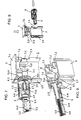
- Fig. 1
- ein Befestigungsset, das an einem oberen Abschnitt einer Hohlprofilstange eines Montagegestells befestigt ist und sich in einem entriegelten Zustand befindet, in einer perspektivischen Seitenansicht;
- Fig. 2
- das Befestigungsset gemäß
Fig. 1 in einer entsprechenden perspektivischen Seitenansicht, wobei jedoch Teile des Befestigungssets und der obere Abschnitt der Hohlprofilstange vertikal geschnitten dargestellt sind; - Fig. 3
- das Befestigungsset gemäß
Fig. 1 in einer entsprechenden perspektivischen Seitenansicht, wobei sich das Befestigungsset in einem verriegelten Zustand befindet; - Fig. 4
- das Befestigungsset gemäß
Fig. 3 in einer entsprechenden perspektivischen Seitenansicht, wobei jedoch Teile des Befestigungssets und der obere Abschnitt der Hohlprofilstange wiederum vertikal geschnitten dargestellt sind; - Fig. 5 und 6
- eine Befestigungsvorrichtung in einer perspektivischen Seitenansicht, in einem entriegelten und einem verriegelten Zustand, wobei axial zueinander verschiebbare Teile der Vorrichtung jeweils axial geschnitten gezeigt sind;
- Fig. 7
- die Vorrichtung aus
Fig. 5 befestigt an einem oberen Abschnitt einer Hohlprofilstange, die vertikal geschnitten ist, ohne Gewindestange, in einer perspektivischen Seitenansicht; - Fig. 8
- die Teile aus
Fig. 7 in einer Explosionsdarstellung; und - Fig. 9
- die Teile aus den
Figuren 7 und 8 horizontal geschnitten, in einer weiteren perspektivischen Ansicht. - Das in der Zeichnung dargestellte Befestigungsset dient der Abstützung und Befestigung eines Montagegestells für Sanitärgegenstände wie zum Beispiel einen Spülkasten, eine WC-Schüssel und/oder ein Waschbecken an einer Gebäudewand. oder an einem Träger. Von dem Montagegestell ist in der Zeichnung lediglich ein oberer Abschnitt einer vertikal auszurichtenden Hohlprofilstange 2 gezeigt. Das Montagegestell weist üblicherweise mindestens zwei vertikal auszurichtende Hohlprofilstangen 2 auf, die durch einen oder mehrere Querträger (Querstreben) miteinander verbunden sind.
- Die Hohlprofilstangen 2 können beispielsweise aus Vierkantrohren oder aus offenen Profilstangen, die im Querschnitt im Wesentlichen C-förmig ausgebildet sind, bestehen. Des Weiteren können die Hohlprofilstangen 2 an mindestens zwei ihrer benachbarten Längskanten ausgebildete Längsnuten 2.1, 2.2 aufweisen, die dem formschlüssigen Anklemmen eines Verbinders zum Befestigen einer oder mehrerer weiterer Hohlprofilstangen dienen.
- Das Befestigungsset ist aus einem an einer Gebäudewand zu befestigenden Befestigungsteil 3, einem mit dem Montagegestell lösbar verbindbaren, kanalförmigen Verbindungsteil 5, einer Verbindungsstange 4, die in dem Verbindungsteil 5 gelagert ist, und einem Steckteil 7 zusammengesetzt. Das Steckteil 7 wird zur axialen Festlegung des Verbindungsteils 5 an dem Montagegestell in eine Öffnung 2.6 einer Hohlprofilstange 2 des Montagegestells formschlüssig eingesetzt. Das Steckteil 7 fixiert und sperrt im montierten Zustand das Verbindungsteil 5 und die Hohlprofilstange 2 zueinander.
- Die Verbindungsstange 4 ist als bolzen- oder stangenförmiges Schraubelement ausgeführt. Sie kann auch als Gewindestange bezeichnet werden und besitzt zumindest über einen Längenabschnitt ein Außengewinde 4.1.
- Jeweils am oberen Ende der vertikal auszurichtenden Hohlprofilstangen 2 des Montagegestells sind zwei gegenüberliegende Durchgangsöffnungen (Löcher) 2.3, 2.4 eingearbeitet, die der Befestigung des Verbindungsteils 5 dienen. Das Verbindungsteil 5 weist hierzu einen radial vorstehenden Verbindungsabschnitt 5.1 auf, über den es formschlüssig mit dem Montagegestell verbindbar ist. Der Verbindungsabschnitt 5.1 ist derart ausgebildet, dass über ihn das Verbindungsteil 5 mittels des Steckteils 7 am Montagegestell axial festlegbar ist.
- Hierzu weist der Verbindungsabschnitt 5.1 einen Spalt 5.2 auf, in den ein Abschnitt des Montagegestells, nämlich ein die Durchgangsöffnung 2.4 begrenzender Abschnitt der Hohlprofilstange 2 einbringbar ist. Der Spalt 5.2 ist durch zwei an dem kanalförmigen Verbindungsteil angeformte Flansche 5.3, 5.4 definiert.
- Der am stirnseitigen Ende des kanalförmigen Verbindungsteils 5 angeordnete Flansch 5.3 ist vorzugsweise kreisförmig ausgebildet. Der dazu axial beabstandete Flansch 5.4 ist oval ausgebildet. Der Spalt 5.2 oder axiale Abstand zwischen den beiden Flanschen 5.3, 5.4 entspricht der Wandstärke oder ist geringfügig größer als die Wandstärke der Hohlprofilstange 2.
- Die beiden Durchgangsöffnungen 2.3, 2.4 der Hohlprofilstange 2 sind ebenfalls unterschiedlich ausgebildet. Die Öffnung 2.3, die in der dem Raum zugewandten Hohlprofilstangenseite eingearbeitet ist, ist vorzugsweise als kreisrundes Loch ausgeführt, während die andere Öffnung 2.4, die in der der Gebäudewand zugewandten Hohlprofilstangenseite eingearbeitet ist, als ovales Loch ausgeführt ist. Der kleinste Innenweite des ovalen Lochs 2.4 ist deutlich kleiner als der Durchmesser der anderen Öffnung 2.3 und auch deutlich kleiner als der Außendurchmesser des kreisförmigen Flansches 5.3 des kanalförmigen Verbindungsteils. Die Durchgangsöffnungen 2.3, 2.4 sind so bemessen, dass das Verbindungsteil 5 über die kreisförmige Öffnung 2.3 hindurch soweit in die ovale Öffnung 2.4 eingeführt werden kann, bis der kreisförmige Flansch 5.3 an der Innenseite der die ovale Öffnung 2.4 aufweisenden Wandung 2.5 der Hohlprofilstange 2 anschlägt (vgl.
Figuren 8 und 9 ). Der ovale Flansch 5.4 wird dabei durch das ovale Loch 2.4 hindurchgeführt und befindet sich dann an der Außenseite der Wandung 2.5. - Anschließend wird das Steckteil 7 von oben in die Hohlprofilstange 2 eingesteckt, um das Verbindungsteil 5 am Montagegestell axial festzulegen. Das Steckteil 7 ist vorzugsweise als Stopfen oder Kappe ausgebildet, um die obere Endöffnung 2.6 der Hohlprofilstange 2 zu verschließen. Das Steckteil 7, das auch als Verschlusskappe bezeichnet werden kann, weist einen deckelartigen Abschnitt 7.1 auf, dessen Oberseite vorzugsweise im Wesentlichen eben ausgebildet ist. An der Unterseite des deckelartigen Abschnitts 7.1 sind in die Hohlprofilstange 2 einsteckbare Stege oder Vorsprünge 7.2, 7.3 ausgebildet. Einer dieser Vorsprünge ist beispielsweise in Form eines umlaufenden Kragens 7.2 ausgebildet, der vier im Wesentlichen rechtwinklig zueinander angeordnete Seitenabschnitte aufweist, wobei der jeweilige Seitenabschnitt eine konkave Einbuchtung 7.21 aufweist. In eine dieser Einbuchtungen 7.21 greift teilweise der kreisförmige Flansch 5.3 des Verbindungsteils 5 ein. Die Seitenabschnitte des kragenförmigen Vorsprungs 7.2 verlaufen im montierten Zustand der Verschlusskappe 7 nahe oder dicht an den Innenseiten der Hohlprofilstange 2 (vgl.
Figuren 2 und 4 ). - Die anderen Vorsprünge 7.3 der Kappe 7 sind in Form von Stegen ausgebildet, die innerhalb des Kragens 7.2 angeordnet sind. Die Stege 7.3 ragen deutlich tiefer in die Hohlprofilstange 2 als der kragenförmige Vorsprung 7.2. Die Stege (Vorsprünge) 7.3 weisen jeweils ein im Wesentlichen L- oder winkelförmiges Querschnittprofil auf. Sie begrenzen einen kreuzförmigen Durchgang (vgl.
Fig. 9 ), wobei die Verbindungsstange (Gewindestange) 4 im montierten Zustand des Befestigungssets koaxial zu einer der sich kreuzenden Achsen des Durchgangs 8 verläuft. Die im montierten Zustand der Kappe 7 vertikal verlaufenden Kanten 7.31 zweier der Stege (Vorsprünge) 7.3 liegen unmittelbar oder mit geringem Spiel an dem kreisförmigen Flansch 5.3 des eingesetzten Verbindungsteils an, so dass das Verbindungsteil 5 an dem Montagegestell bzw. der Hohlprofilstange 2 axial festgelegt ist. - Das an einer Gebäudewand anzubringende Befestigungsteil 3 weist ein Gewindeloch 3.1 auf, in welches die als Gewindestange ausgeführte Verbindungsstange 4 einschraubbar ist. Das Befestigungsteil 3 besitzt einen plattenförmigen Abschnitt 3.2 mit einer Durchgangsöffnung 3.3 zum Anbringen einer Befestigungsschraube (nicht gezeigt), wobei der Kopf der Schraube im montierten Zustand vorzugsweise mit einer Unterlegscheibe an der Innenseite des Befestigungsteils 3 anliegt. Die Durchgangsöffnung 3.3 ist vorzugsweise als Langloch ausgebildet. Des Weiteren weist das Befestigungsteil 3 von dem plattenförmigen Abschnitt abstehende Stege 3.4 auf. Die Stege 3.4 schließen einen das Gewindeloch 3.1 zum Einschrauben der Gewindestange 4 aufweisenden Schraubdom 3.5 ein bzw. sind an den Schraubdom 3.5 angeformt. Das dem Montagegestell zugewandte Ende des Schraubdoms 3.5 sowie die dem Montagegestell zugewandten Kanten der Stege 3.4 schließen vorzugsweise im Wesentlichen flächenbündig zueinander ab.
- Die Verbindungsstange (Gewindestange) 4 ist in dem kanalförmigen Verbindungsteil 5 axial verschiebbar geführt. Das Verbindungsteil 5 weist einen hülsenförmigen Abschnitt 5.5 auf, an den sich axial ein rinnenförmiger Abschnitt 5.6 anschließt. Die Flansche 5.3, 5.4 sind an dem hülsenförmigen Abschnitt 5.5 angeordnet. Das Verbindungsteil 5 hat entlang seines hülsenförmigen Abschnitts 5.5 eine ovale Innenquerschnittsfläche. Die Innenseite des hülsenförmigen Abschnitts 5.5 ist vorzugsweise glatt oder im Wesentlichen glatt ausgebildet. Die kleinste Innenweite der ovalen Innenquerschnittsfläche des hülsenförmigen Abschnitts 5.5 ist geringfügig größer als der Außendurchmesser des Gewindes 4.1 der Verbindungsstange 4. Der rinnenförmige Abschnitt 5.6 des Verbindungsteils 5 weist innenseitig ein rinnenförmiges Innenteilgewinde 5.7 auf (vgl.
Fig. 5 ,7 und 9 ). - Das Innenteilgewinde 5.7 ist passend zu dem Außengewinde 4.1 der Verbindungsstange 4 ausgebildet. Durch eine bestimmte Radialverschiebung bzw. ein geringfügiges Absenken des am Montagegestell axial festgelegten Verbindungsteils 5 gegenüber der am Befestigungsteil 3 befestigten Verbindungsstange (Gewindestange) 4 können das rinnenförmige Innenteilgewinde 5.7 des Verbindungsteils und das Außengewinde 4.1 der Verbindungsstange außer Eingriff gebracht und das Verbindungsteil 5 sodann entlang der Verbindungsstange 4 axial verschoben werden. Die besagte Radialverschiebung und die axiale Verschiebung sind in
Fig. 5 durch einen kleinen vertikalen Pfeil P bzw. einen Doppelpfeil D angedeutet. - Auf dem kanalförmigen Verbindungsteil 5 sitzt der als Schieber ausgebildete Riegel 6. Er ist axial zur Längsachse des Verbindungsteils 5 aus einer Nicht-Kontaktstellung in eine Kontaktstellung und umgekehrt verschiebbar und weist einen der Verbindungsstange (Gewindestange) 4 zugewandten Kontaktabschnitt 6.1 auf, der in der Kontaktstellung am Außengewinde 4.1 der Verbindungsstange anliegt. Der Kontaktabschnitt 6.1 des Riegels ist als Vorsprung ausgebildet. Die Längsöffnung 5.61 des rinnenförmigen Abschnitts 5.6 des Verbindungsteils definiert eine Axialführung für den Riegel 6, wobei der Kontaktabschnitt 6.1 des Riegels in der Verriegelungsstellung in der Längsöffnung 5.61 aufgenommen ist.
- In den
Figuren 2 und4 bis 6 ist gut zu erkennen, dass das kanalförmige Verbindungsteil 5 an seiner Außenseite zwei radiale Absätze 5.8, 5.9 aufweist, die an entgegengesetzten Umfangsabschnitten des Verbindungsteils 5 angeordnet und axial voneinander beabstandet sind. Beide Absätze 5.8, 5.9 haben jeweils eine schräg zur Längsachse des Verbindungsteils 5 verlaufende Gleitkante oder Gleitfläche 5.81, 5.91. Die beiden Gleitkanten bzw. Gleitflächen 5.81, 5.91 sind an einander zugewandten Enden der beiden Absätze 5.8, 5.9 ausgebildet. Zudem ist am Übergang zwischen dem rinnenförmigen Abschnitt 5.6 und dem hülsenförmigen Abschnitt 5.5, und zwar am Rand der Längsöffnung 5.61 eine schräg zur Längsachse des Verbindungsteils 5 verlaufende Gleitkante oder Gleitfläche 5.10 ausgebildet. - Der Riegel 6 weist innenseitig eine den Gleitkanten oder Gleitflächen 5.81, 5.10 zugeordnete Gleitkante oder Gleitfläche 6.8 auf, die ebenfalls schräg zur Längsachse des Riegels 6 bzw. des Verbindungsteils 5 verläuft.
- Des Weiteren besitzt das kanalförmige Verbindungsteil 5 an seiner Außenseite axial voneinander beabstandete Vertiefungen 5.11, 5.12, denen ein mit dem Riegel 6 verbundenes Rastelement 6.2 zugeordnet ist. Das Rastelement 6.2 ist beispielsweise in Form einer federelastischen Rastlasche ausgebildet. Es rastet in zwei verschiedenen Positionen des Riegels 6 relativ zu dem Verbindungsteil 5 in eine der beiden Vertiefungen 5.11, 5.12 ein. Die Vertiefungen 5.11, 5.12 sind einerseits einem Entriegelungszustand und andererseits einem Verriegelungszustand zugeordnet. Die möglichen Bewegungsrichtungen des Riegels 6 sind durch eingeprägte oder aufgedruckte Doppelpfeile 6.3 markiert. Zudem ist der Riegel 6 mit zwei Symbolen 6.4, 6.5 versehen, welche ein geschlossenes und ein geöffnetes Bügelschloss symbolisieren und in Kombination mit den Doppelpfeilen 6.3 die Verschieberichtung zur Einstellung des Entriegelungszustandes bzw. des Verriegelungszustandes anzeigen. Darüber hinaus weist der Riegel 6 auf seiner Außenfläche zwei entgegengesetzt angeordnete Rippenflächen 6.6, 6.7 auf, die als rutschhemmende Griffflächen die manuelle, werkzeuglose Verschiebung des Riegels 6 erleichtern.
- In der Verriegelungsstellung bildet der Riegel 6 zusammen mit dem kanalförmigen Verbindungsteil 5 eine (zweiteilige) Mutter. In dieser Stellung kann der Riegel 6 zusammen mit dem Verbindungsteil 5 um die Längsachse des Schraubelements 4 gedreht werden und damit eine Feineinstellung der Montagetiefe des Montagegestells vorgenommen werden. Für eine schnelle Grobeinstellung der Montagetiefe wird der Riegel 6 in die Entriegelungsstellung geschoben und dabei der Eingriff des Innenteilgewindes 5.7 des Verbindungsteils 5 in das Außengewinde 4.1 des Schraubelements 4 durch eine Radialbewegung des Verbindungsteils 5 gelöst. Sodann können die Verbindungsstange (Gewindestange) 4 und das kanalförmige Verbindungsteil 5 relativ zueinander axial verschoben und damit die Montagetiefe des Montagegestells schnell und grob eingestellt werden. Danach werden das Innenteilgewinde 5.7 des Verbindungsteils und das Außengewinde 4.1 der Verbindungsstange durch eine umgekehrte Radialbewegung des Verbindungsteils 5 wieder in Eingriff gebracht und durch Verschiebung des Riegels 6 in die Verriegelungsstellung verriegelt. Bei Bedarf kann dann durch Drehen des Riegels 6 zusammen mit dem damit verriegelten Verbindungsteil 5 um die Längsachse der Gewindestange 4 eine Feineinstellung der Montagetiefe vorgenommen werden.
Claims (14)
- Befestigungsset zum Befestigen eines Montagegestells für Sanitärobjekte, insbesondere für einen Spülkasten, eine WC-Schüssel und/oder ein Waschbecken, an einer Gebäudewand, wobei das Montagegestell aus Hohlprofilstangen gebildet ist,
mit einem mit dem Montagegestell lösbar verbindbaren, kanalförmigen Verbindungsteil (5), das einen radial vorstehenden Verbindungsabschnitt (5.1) aufweist,
mit einer Verbindungsstange (4), die in dem Verbindungsteil (5) gelagert ist, mit einem an einem Ende der Verbindungsstange (4) angebrachten Befestigungsteil (3), das an einer Gebäudewand befestigbar ist, und
mit einem Steckteil (7),
dadurch gekennzeichnet, dass das Steckteil (7) zur axialen Festlegung des Verbindungsteils (5) an dem Montagegestell in eine Öffnung (2.6) einer Hohlprofilstange (2) des Montagegestells einsetzbar ist und im montierten Zustand das Verbindungsteil (5) und die Hohlprofilstange (2) zueinander sperrt, wobei der Verbindungsabschnitt (5.1) einen Spalt (5.2) aufweist, in den ein Abschnitt einer Hohlprofilstangenwand (2.5) des Montagegestells einbringbar ist. - Befestigungsset nach Anspruch 1, dadurch gekennzeichnet, dass das Steckteil (7) als Kappe oder Stopfen ausgebildet ist, die/der in eine vertikale Hohlprofilstange (2) des Montagegestells einsteckbar ist.
- Befestigungsset nach Anspruch 1 oder 2, dadurch gekennzeichnet, dass das Steckteil (7) einen deckelartigen Abschnitt (7.1) aufweist, dessen Oberseite vorzugsweise im Wesentlichen eben ausgebildet ist.
- Befestigungsset nach Anspruch 3, dadurch gekennzeichnet, dass das Steckteil (7) an der Unterseite des deckelartigen Abschnitts (7.1) mehrere Vorsprünge (7.2, 7.3) aufweist, wobei mindestens einer der Vorsprünge (7.2) im montierten Zustand des Befestigungssets die Lage des Steckteils (7) relativ zu der Hohlprofilstange (2) festlegt, und wobei mindestens ein anderer der Vorsprünge (7.3) im montierten Zustand des Befestigungssets eine Axialverschiebung des Verbindungsteils (5) sperrt.
- Befestigungsset nach Anspruch 4, dadurch gekennzeichnet, dass der die Lage des Steckteils (7) relativ zu der Hohlprofilstange (2) festlegende Vorsprung (7.2) kragenförmig ausgebildet ist.
- Befestigungsset nach Anspruch 4 oder 5, dadurch gekennzeichnet, dass der eine Axialverschiebung des Verbindungsteils (5) sperrende Vorsprung aus mehreren Stegen (7.3) gebildet ist, die einen kreuzförmigen Durchgang begrenzen.
- Befestigungsset nach Anspruch 6, dadurch gekennzeichnet, dass der jeweilige Steg (7.3) ein L- oder winkelförmiges Querschnittprofil aufweist.
- Befestigungsset nach einem der Ansprüche 1 bis 7, dadurch gekennzeichnet, dass der Spalt (5.2) durch zwei an dem Verbindungsabschnitt (5.1) ausgebildete Flansche (5.3, 5.4) definiert ist.
- Befestigungsset nach Anspruch 8, dadurch gekennzeichnet, dass
der Flansch (5.3), der im montierten Zustand des Befestigungssets innerhalb der Hohlprofilstange (2) angeordnet ist, kreisförmig oder im Wesentlichen kreisförmig ausgebildet ist. - Befestigungsset nach einem der Ansprüche 8 oder 9, dadurch gekennzeichnet, dass der Flansch (5.4), der im montierten Zustand des Befestigungssets außerhalb der Hohlprofilstange (2) angeordnet ist, nicht-kreisförmig, vorzugsweise im Wesentlichen oval ausgebildet ist.
- Befestigungsset nach den Ansprüchen 9 und 10, dadurch gekennzeichnet, dass der kreisförmige oder im Wesentlichen kreisförmige Flansch (5.3) einen Außendurchmesser aufweist, der größer ist als ein radiales Außenmaß des nicht-kreisförmigen oder im Wesentlichen oval ausgebildeten Flansches (5.4).
- Befestigungsset nach Anspruch 11, dadurch gekennzeichnet, dass der nicht-kreisförmige oder im Wesentlichen ovale Flansch (5.4) ein weiteres radiales Außenmaß aufweist, das größer ist als der Außendurchmesser des kreisförmigen oder im Wesentlichen kreisförmigen Flansches (5.3).
- Befestigungsset nach einem der Ansprüche 1 bis 12, dadurch gekennzeichnet, dass das Verbindungsteil (5) einen Innengewindeabschnitt (5.7) aufweist und/oder dass die Verbindungsstange (4) als Gewindestange ausgeführt ist.
- Verwendung eines Befestigungssets nach einem der Ansprüche 1 bis 13 zum Befestigen eines Montagegestells für ein oder mehrere Sanitärobjekte, insbesondere für einen Spülkasten, eine WC-Schüssel und/oder ein Waschbecken, an einer Gebäudewand.
Priority Applications (1)
| Application Number | Priority Date | Filing Date | Title |
|---|---|---|---|
| PL18166707T PL3404152T3 (pl) | 2017-05-17 | 2018-04-11 | Zestaw mocujący do mocowania stelaża montażowego dla przedmiotów sanitarnych i zastosowanie takiego zestawu mocującego |
Applications Claiming Priority (1)
| Application Number | Priority Date | Filing Date | Title |
|---|---|---|---|
| DE102017110766.5A DE102017110766A1 (de) | 2017-05-17 | 2017-05-17 | Befestigungsset zum Befestigen eines Montagegestells für Sanitärobjekte und Verwendung eines solchen Befestigungssets |
Publications (2)
| Publication Number | Publication Date |
|---|---|
| EP3404152A1 EP3404152A1 (de) | 2018-11-21 |
| EP3404152B1 true EP3404152B1 (de) | 2020-05-27 |
Family
ID=61965838
Family Applications (1)
| Application Number | Title | Priority Date | Filing Date |
|---|---|---|---|
| EP18166707.2A Active EP3404152B1 (de) | 2017-05-17 | 2018-04-11 | Befestigungsset zum befestigen eines montagegestells für sanitärobjekte und verwendung eines solchen befestigungssets |
Country Status (5)
| Country | Link |
|---|---|
| EP (1) | EP3404152B1 (de) |
| DE (1) | DE102017110766A1 (de) |
| DK (1) | DK3404152T3 (de) |
| ES (1) | ES2800436T3 (de) |
| PL (1) | PL3404152T3 (de) |
Families Citing this family (3)
| Publication number | Priority date | Publication date | Assignee | Title |
|---|---|---|---|---|
| EP3792505B1 (de) | 2019-09-13 | 2023-07-12 | Geberit International AG | Gewindeeinheit für eine sanitäre montagestruktur |
| CN110984316A (zh) * | 2019-12-27 | 2020-04-10 | 帝希洁具系统(苏州)有限公司 | 一种用于嵌入式水箱的快速连接结构 |
| CZ34202U1 (cs) * | 2020-06-17 | 2020-07-07 | Alca Plast, S.R.O. | Fixační opěrka pro kotvení nosných rámů sanitárních zařízení ke zdivu |
Family Cites Families (6)
| Publication number | Priority date | Publication date | Assignee | Title |
|---|---|---|---|---|
| DE19507765C2 (de) * | 1995-03-06 | 1998-05-07 | Rost & Co Gmbh | Vorwandelement |
| NO964690L (no) * | 1996-01-25 | 1997-07-28 | Geberit Technik Ag | Holdeinnretning på en monteringsramme for sanitære anordninger |
| PL203127B1 (pl) | 2001-05-21 | 2009-08-31 | Geberit Technik Ag | Wspornik przyścienny ramy montażowej urządzeń sanitarnych |
| ITMI20042115A1 (it) * | 2004-11-04 | 2005-02-04 | Oliveira & Irmao Sa | Dispositivo di fissaggio a parete di una struttura di installazione per apparecchiature sanitarie |
| ITMI20051551A1 (it) * | 2005-08-05 | 2007-02-06 | Oliveira & Irmao Sa | Dispositivo di fissaggio regolabile in particolare per il fissaggio a parete di una struttura di installazione per apparecchiature sanitarie |
| ITMI20122128A1 (it) * | 2012-12-13 | 2014-06-14 | Oliveira & Irmao Sa | Dispositivo di fissaggio a parete di una struttura di installazione per apparecchiature sanitarie |
-
2017
- 2017-05-17 DE DE102017110766.5A patent/DE102017110766A1/de active Pending
-
2018
- 2018-04-11 EP EP18166707.2A patent/EP3404152B1/de active Active
- 2018-04-11 DK DK18166707.2T patent/DK3404152T3/da active
- 2018-04-11 ES ES18166707T patent/ES2800436T3/es active Active
- 2018-04-11 PL PL18166707T patent/PL3404152T3/pl unknown
Non-Patent Citations (1)
| Title |
|---|
| None * |
Also Published As
| Publication number | Publication date |
|---|---|
| DE102017110766A1 (de) | 2018-12-13 |
| ES2800436T3 (es) | 2020-12-30 |
| PL3404152T3 (pl) | 2020-09-21 |
| EP3404152A1 (de) | 2018-11-21 |
| DK3404152T3 (da) | 2020-06-22 |
Similar Documents
| Publication | Publication Date | Title |
|---|---|---|
| EP3404151B1 (de) | Vorrichtung zum befestigen eines sanitärgegenstandes und verwendung einer solchen vorrichtung | |
| DE69806907T2 (de) | Verschlussvorrichtung für eine tür | |
| EP3404152B1 (de) | Befestigungsset zum befestigen eines montagegestells für sanitärobjekte und verwendung eines solchen befestigungssets | |
| EP2808457A2 (de) | Wasserablaufvorrichtung für eine sanitäre Anlage, wie einen bodenebenen Duschplatz | |
| EP2055867A1 (de) | Griff mit Verschlusseinsatz | |
| DE212020000339U1 (de) | Tragvorrichtung für Möbelfachböden | |
| EP3760076A1 (de) | Verbindungsstift für möbelteile | |
| EP3404153B1 (de) | Befestigungsset zum befestigen eines montagegestells für sanitärobjekte und verwendung eines solchen befestigungssets | |
| EP1072745B1 (de) | Beschlag für die Verriegelung von Fenstern oder Türen | |
| EP4018100B1 (de) | Verbindungsbeschlag | |
| DE202016101091U1 (de) | Türverriegelung | |
| AT519915A1 (de) | Dübel zum Befestigen von Beschlagteilen | |
| DE10309946B4 (de) | Schloß | |
| EP3269903B1 (de) | Rosettengarnitur für drücker bei türen oder fenstern | |
| DE4339042C1 (de) | Vorrichtung zur Befestigung eines Bauteils an einem Verbindungsstift | |
| DE10001662A1 (de) | Schutzbeschlag | |
| DE69002342T2 (de) | Befestigungsvorrichtung durch Zusammenschrauben auf einem Profil, insbesondere auf einem Elektrizitätsschrank. | |
| EP0454077A2 (de) | Stangenführung für die Stange eines Stangenverschlusses | |
| DE10309947B4 (de) | Schloß | |
| DE102005002298A1 (de) | Griffbefestigungsverfahren und -system | |
| EP1039046B1 (de) | Wandhalter | |
| DE29800615U1 (de) | Rosette | |
| EP1428941A2 (de) | Anordnung zur Anbringung eines Sanitärgegenstands | |
| DE10344457A1 (de) | Aufhängevorrichtung | |
| DE19717188C1 (de) | Dreh- oder Schubstangenschloß |
Legal Events
| Date | Code | Title | Description |
|---|---|---|---|
| PUAI | Public reference made under article 153(3) epc to a published international application that has entered the european phase |
Free format text: ORIGINAL CODE: 0009012 |
|
| STAA | Information on the status of an ep patent application or granted ep patent |
Free format text: STATUS: THE APPLICATION HAS BEEN PUBLISHED |
|
| AK | Designated contracting states |
Kind code of ref document: A1 Designated state(s): AL AT BE BG CH CY CZ DE DK EE ES FI FR GB GR HR HU IE IS IT LI LT LU LV MC MK MT NL NO PL PT RO RS SE SI SK SM TR |
|
| AX | Request for extension of the european patent |
Extension state: BA ME |
|
| STAA | Information on the status of an ep patent application or granted ep patent |
Free format text: STATUS: REQUEST FOR EXAMINATION WAS MADE |
|
| 17P | Request for examination filed |
Effective date: 20190507 |
|
| RBV | Designated contracting states (corrected) |
Designated state(s): AL AT BE BG CH CY CZ DE DK EE ES FI FR GB GR HR HU IE IS IT LI LT LU LV MC MK MT NL NO PL PT RO RS SE SI SK SM TR |
|
| GRAP | Despatch of communication of intention to grant a patent |
Free format text: ORIGINAL CODE: EPIDOSNIGR1 |
|
| STAA | Information on the status of an ep patent application or granted ep patent |
Free format text: STATUS: GRANT OF PATENT IS INTENDED |
|
| INTG | Intention to grant announced |
Effective date: 20200103 |
|
| GRAS | Grant fee paid |
Free format text: ORIGINAL CODE: EPIDOSNIGR3 |
|
| GRAA | (expected) grant |
Free format text: ORIGINAL CODE: 0009210 |
|
| STAA | Information on the status of an ep patent application or granted ep patent |
Free format text: STATUS: THE PATENT HAS BEEN GRANTED |
|
| AK | Designated contracting states |
Kind code of ref document: B1 Designated state(s): AL AT BE BG CH CY CZ DE DK EE ES FI FR GB GR HR HU IE IS IT LI LT LU LV MC MK MT NL NO PL PT RO RS SE SI SK SM TR |
|
| REG | Reference to a national code |
Ref country code: GB Ref legal event code: FG4D Free format text: NOT ENGLISH |
|
| REG | Reference to a national code |
Ref country code: CH Ref legal event code: EP |
|
| REG | Reference to a national code |
Ref country code: AT Ref legal event code: REF Ref document number: 1274686 Country of ref document: AT Kind code of ref document: T Effective date: 20200615 |
|
| REG | Reference to a national code |
Ref country code: DE Ref legal event code: R096 Ref document number: 502018001515 Country of ref document: DE |
|
| REG | Reference to a national code |
Ref country code: DK Ref legal event code: T3 Effective date: 20200617 |
|
| REG | Reference to a national code |
Ref country code: CH Ref legal event code: NV Representative=s name: ISLER AND PEDRAZZINI AG, CH |
|
| REG | Reference to a national code |
Ref country code: NL Ref legal event code: FP |
|
| REG | Reference to a national code |
Ref country code: LT Ref legal event code: MG4D |
|
| PG25 | Lapsed in a contracting state [announced via postgrant information from national office to epo] |
Ref country code: IS Free format text: LAPSE BECAUSE OF FAILURE TO SUBMIT A TRANSLATION OF THE DESCRIPTION OR TO PAY THE FEE WITHIN THE PRESCRIBED TIME-LIMIT Effective date: 20200927 Ref country code: PT Free format text: LAPSE BECAUSE OF FAILURE TO SUBMIT A TRANSLATION OF THE DESCRIPTION OR TO PAY THE FEE WITHIN THE PRESCRIBED TIME-LIMIT Effective date: 20200928 Ref country code: FI Free format text: LAPSE BECAUSE OF FAILURE TO SUBMIT A TRANSLATION OF THE DESCRIPTION OR TO PAY THE FEE WITHIN THE PRESCRIBED TIME-LIMIT Effective date: 20200527 Ref country code: GR Free format text: LAPSE BECAUSE OF FAILURE TO SUBMIT A TRANSLATION OF THE DESCRIPTION OR TO PAY THE FEE WITHIN THE PRESCRIBED TIME-LIMIT Effective date: 20200828 Ref country code: NO Free format text: LAPSE BECAUSE OF FAILURE TO SUBMIT A TRANSLATION OF THE DESCRIPTION OR TO PAY THE FEE WITHIN THE PRESCRIBED TIME-LIMIT Effective date: 20200827 Ref country code: SE Free format text: LAPSE BECAUSE OF FAILURE TO SUBMIT A TRANSLATION OF THE DESCRIPTION OR TO PAY THE FEE WITHIN THE PRESCRIBED TIME-LIMIT Effective date: 20200527 Ref country code: LT Free format text: LAPSE BECAUSE OF FAILURE TO SUBMIT A TRANSLATION OF THE DESCRIPTION OR TO PAY THE FEE WITHIN THE PRESCRIBED TIME-LIMIT Effective date: 20200527 |
|
| PG25 | Lapsed in a contracting state [announced via postgrant information from national office to epo] |
Ref country code: BG Free format text: LAPSE BECAUSE OF FAILURE TO SUBMIT A TRANSLATION OF THE DESCRIPTION OR TO PAY THE FEE WITHIN THE PRESCRIBED TIME-LIMIT Effective date: 20200827 Ref country code: HR Free format text: LAPSE BECAUSE OF FAILURE TO SUBMIT A TRANSLATION OF THE DESCRIPTION OR TO PAY THE FEE WITHIN THE PRESCRIBED TIME-LIMIT Effective date: 20200527 Ref country code: LV Free format text: LAPSE BECAUSE OF FAILURE TO SUBMIT A TRANSLATION OF THE DESCRIPTION OR TO PAY THE FEE WITHIN THE PRESCRIBED TIME-LIMIT Effective date: 20200527 Ref country code: RS Free format text: LAPSE BECAUSE OF FAILURE TO SUBMIT A TRANSLATION OF THE DESCRIPTION OR TO PAY THE FEE WITHIN THE PRESCRIBED TIME-LIMIT Effective date: 20200527 |
|
| PG25 | Lapsed in a contracting state [announced via postgrant information from national office to epo] |
Ref country code: AL Free format text: LAPSE BECAUSE OF FAILURE TO SUBMIT A TRANSLATION OF THE DESCRIPTION OR TO PAY THE FEE WITHIN THE PRESCRIBED TIME-LIMIT Effective date: 20200527 |
|
| PG25 | Lapsed in a contracting state [announced via postgrant information from national office to epo] |
Ref country code: EE Free format text: LAPSE BECAUSE OF FAILURE TO SUBMIT A TRANSLATION OF THE DESCRIPTION OR TO PAY THE FEE WITHIN THE PRESCRIBED TIME-LIMIT Effective date: 20200527 Ref country code: SM Free format text: LAPSE BECAUSE OF FAILURE TO SUBMIT A TRANSLATION OF THE DESCRIPTION OR TO PAY THE FEE WITHIN THE PRESCRIBED TIME-LIMIT Effective date: 20200527 Ref country code: CZ Free format text: LAPSE BECAUSE OF FAILURE TO SUBMIT A TRANSLATION OF THE DESCRIPTION OR TO PAY THE FEE WITHIN THE PRESCRIBED TIME-LIMIT Effective date: 20200527 Ref country code: RO Free format text: LAPSE BECAUSE OF FAILURE TO SUBMIT A TRANSLATION OF THE DESCRIPTION OR TO PAY THE FEE WITHIN THE PRESCRIBED TIME-LIMIT Effective date: 20200527 |
|
| PG25 | Lapsed in a contracting state [announced via postgrant information from national office to epo] |
Ref country code: SK Free format text: LAPSE BECAUSE OF FAILURE TO SUBMIT A TRANSLATION OF THE DESCRIPTION OR TO PAY THE FEE WITHIN THE PRESCRIBED TIME-LIMIT Effective date: 20200527 |
|
| REG | Reference to a national code |
Ref country code: DE Ref legal event code: R097 Ref document number: 502018001515 Country of ref document: DE |
|
| PLBE | No opposition filed within time limit |
Free format text: ORIGINAL CODE: 0009261 |
|
| STAA | Information on the status of an ep patent application or granted ep patent |
Free format text: STATUS: NO OPPOSITION FILED WITHIN TIME LIMIT |
|
| 26N | No opposition filed |
Effective date: 20210302 |
|
| PG25 | Lapsed in a contracting state [announced via postgrant information from national office to epo] |
Ref country code: SI Free format text: LAPSE BECAUSE OF FAILURE TO SUBMIT A TRANSLATION OF THE DESCRIPTION OR TO PAY THE FEE WITHIN THE PRESCRIBED TIME-LIMIT Effective date: 20200527 |
|
| PG25 | Lapsed in a contracting state [announced via postgrant information from national office to epo] |
Ref country code: MC Free format text: LAPSE BECAUSE OF FAILURE TO SUBMIT A TRANSLATION OF THE DESCRIPTION OR TO PAY THE FEE WITHIN THE PRESCRIBED TIME-LIMIT Effective date: 20200527 |
|
| PG25 | Lapsed in a contracting state [announced via postgrant information from national office to epo] |
Ref country code: LU Free format text: LAPSE BECAUSE OF NON-PAYMENT OF DUE FEES Effective date: 20210411 |
|
| PG25 | Lapsed in a contracting state [announced via postgrant information from national office to epo] |
Ref country code: IE Free format text: LAPSE BECAUSE OF NON-PAYMENT OF DUE FEES Effective date: 20210411 |
|
| PG25 | Lapsed in a contracting state [announced via postgrant information from national office to epo] |
Ref country code: CY Free format text: LAPSE BECAUSE OF FAILURE TO SUBMIT A TRANSLATION OF THE DESCRIPTION OR TO PAY THE FEE WITHIN THE PRESCRIBED TIME-LIMIT Effective date: 20200527 |
|
| PG25 | Lapsed in a contracting state [announced via postgrant information from national office to epo] |
Ref country code: HU Free format text: LAPSE BECAUSE OF FAILURE TO SUBMIT A TRANSLATION OF THE DESCRIPTION OR TO PAY THE FEE WITHIN THE PRESCRIBED TIME-LIMIT; INVALID AB INITIO Effective date: 20180411 |
|
| PG25 | Lapsed in a contracting state [announced via postgrant information from national office to epo] |
Ref country code: MK Free format text: LAPSE BECAUSE OF FAILURE TO SUBMIT A TRANSLATION OF THE DESCRIPTION OR TO PAY THE FEE WITHIN THE PRESCRIBED TIME-LIMIT Effective date: 20200527 |
|
| PGFP | Annual fee paid to national office [announced via postgrant information from national office to epo] |
Ref country code: NL Payment date: 20240423 Year of fee payment: 7 |
|
| REG | Reference to a national code |
Ref country code: AT Ref legal event code: MM01 Ref document number: 1274686 Country of ref document: AT Kind code of ref document: T Effective date: 20230411 |
|
| PGFP | Annual fee paid to national office [announced via postgrant information from national office to epo] |
Ref country code: GB Payment date: 20240422 Year of fee payment: 7 |
|
| PGFP | Annual fee paid to national office [announced via postgrant information from national office to epo] |
Ref country code: DE Payment date: 20240422 Year of fee payment: 7 |
|
| PGFP | Annual fee paid to national office [announced via postgrant information from national office to epo] |
Ref country code: DK Payment date: 20240430 Year of fee payment: 7 |
|
| PGFP | Annual fee paid to national office [announced via postgrant information from national office to epo] |
Ref country code: CH Payment date: 20240501 Year of fee payment: 7 |
|
| PGFP | Annual fee paid to national office [announced via postgrant information from national office to epo] |
Ref country code: ES Payment date: 20240522 Year of fee payment: 7 |
|
| PG25 | Lapsed in a contracting state [announced via postgrant information from national office to epo] |
Ref country code: AT Free format text: LAPSE BECAUSE OF NON-PAYMENT OF DUE FEES Effective date: 20230411 |
|
| PG25 | Lapsed in a contracting state [announced via postgrant information from national office to epo] |
Ref country code: AT Free format text: LAPSE BECAUSE OF NON-PAYMENT OF DUE FEES Effective date: 20230411 |
|
| PGFP | Annual fee paid to national office [announced via postgrant information from national office to epo] |
Ref country code: IT Payment date: 20240423 Year of fee payment: 7 Ref country code: FR Payment date: 20240422 Year of fee payment: 7 |
|
| PGFP | Annual fee paid to national office [announced via postgrant information from national office to epo] |
Ref country code: PL Payment date: 20240405 Year of fee payment: 7 |
|
| PGFP | Annual fee paid to national office [announced via postgrant information from national office to epo] |
Ref country code: BE Payment date: 20240422 Year of fee payment: 7 |