EP3402695B1 - Component comprising a flat decorative element and a housing - Google Patents
Component comprising a flat decorative element and a housing Download PDFInfo
- Publication number
- EP3402695B1 EP3402695B1 EP16798174.5A EP16798174A EP3402695B1 EP 3402695 B1 EP3402695 B1 EP 3402695B1 EP 16798174 A EP16798174 A EP 16798174A EP 3402695 B1 EP3402695 B1 EP 3402695B1
- Authority
- EP
- European Patent Office
- Prior art keywords
- layer
- housing
- component
- diffuser
- hardness
- Prior art date
- Legal status (The legal status is an assumption and is not a legal conclusion. Google has not performed a legal analysis and makes no representation as to the accuracy of the status listed.)
- Active
Links
Images


Classifications
-
- B—PERFORMING OPERATIONS; TRANSPORTING
- B60—VEHICLES IN GENERAL
- B60Q—ARRANGEMENT OF SIGNALLING OR LIGHTING DEVICES, THE MOUNTING OR SUPPORTING THEREOF OR CIRCUITS THEREFOR, FOR VEHICLES IN GENERAL
- B60Q1/00—Arrangement of optical signalling or lighting devices, the mounting or supporting thereof or circuits therefor
- B60Q1/26—Arrangement of optical signalling or lighting devices, the mounting or supporting thereof or circuits therefor the devices being primarily intended to indicate the vehicle, or parts thereof, or to give signals, to other traffic
- B60Q1/32—Arrangement of optical signalling or lighting devices, the mounting or supporting thereof or circuits therefor the devices being primarily intended to indicate the vehicle, or parts thereof, or to give signals, to other traffic for indicating vehicle sides, e.g. clearance lights
- B60Q1/325—Arrangement of optical signalling or lighting devices, the mounting or supporting thereof or circuits therefor the devices being primarily intended to indicate the vehicle, or parts thereof, or to give signals, to other traffic for indicating vehicle sides, e.g. clearance lights on or for running boards or steps
-
- B—PERFORMING OPERATIONS; TRANSPORTING
- B60—VEHICLES IN GENERAL
- B60Q—ARRANGEMENT OF SIGNALLING OR LIGHTING DEVICES, THE MOUNTING OR SUPPORTING THEREOF OR CIRCUITS THEREFOR, FOR VEHICLES IN GENERAL
- B60Q3/00—Arrangement of lighting devices for vehicle interiors; Lighting devices specially adapted for vehicle interiors
- B60Q3/60—Arrangement of lighting devices for vehicle interiors; Lighting devices specially adapted for vehicle interiors characterised by optical aspects
- B60Q3/62—Arrangement of lighting devices for vehicle interiors; Lighting devices specially adapted for vehicle interiors characterised by optical aspects using light guides
- B60Q3/64—Arrangement of lighting devices for vehicle interiors; Lighting devices specially adapted for vehicle interiors characterised by optical aspects using light guides for a single lighting device
-
- B—PERFORMING OPERATIONS; TRANSPORTING
- B60—VEHICLES IN GENERAL
- B60Q—ARRANGEMENT OF SIGNALLING OR LIGHTING DEVICES, THE MOUNTING OR SUPPORTING THEREOF OR CIRCUITS THEREFOR, FOR VEHICLES IN GENERAL
- B60Q3/00—Arrangement of lighting devices for vehicle interiors; Lighting devices specially adapted for vehicle interiors
- B60Q3/70—Arrangement of lighting devices for vehicle interiors; Lighting devices specially adapted for vehicle interiors characterised by the purpose
- B60Q3/78—Arrangement of lighting devices for vehicle interiors; Lighting devices specially adapted for vehicle interiors characterised by the purpose for generating luminous strips, e.g. for marking trim component edges
-
- B—PERFORMING OPERATIONS; TRANSPORTING
- B60—VEHICLES IN GENERAL
- B60R—VEHICLES, VEHICLE FITTINGS, OR VEHICLE PARTS, NOT OTHERWISE PROVIDED FOR
- B60R13/00—Elements for body-finishing, identifying, or decorating; Arrangements or adaptations for advertising purposes
- B60R13/02—Internal Trim mouldings ; Internal Ledges; Wall liners for passenger compartments; Roof liners
-
- F—MECHANICAL ENGINEERING; LIGHTING; HEATING; WEAPONS; BLASTING
- F21—LIGHTING
- F21S—NON-PORTABLE LIGHTING DEVICES; SYSTEMS THEREOF; VEHICLE LIGHTING DEVICES SPECIALLY ADAPTED FOR VEHICLE EXTERIORS
- F21S45/00—Arrangements within vehicle lighting devices specially adapted for vehicle exteriors, for purposes other than emission or distribution of light
- F21S45/50—Waterproofing
-
- G—PHYSICS
- G02—OPTICS
- G02B—OPTICAL ELEMENTS, SYSTEMS OR APPARATUS
- G02B6/00—Light guides; Structural details of arrangements comprising light guides and other optical elements, e.g. couplings
- G02B6/0001—Light guides; Structural details of arrangements comprising light guides and other optical elements, e.g. couplings specially adapted for lighting devices or systems
- G02B6/0011—Light guides; Structural details of arrangements comprising light guides and other optical elements, e.g. couplings specially adapted for lighting devices or systems the light guides being planar or of plate-like form
- G02B6/0033—Means for improving the coupling-out of light from the light guide
- G02B6/005—Means for improving the coupling-out of light from the light guide provided by one optical element, or plurality thereof, placed on the light output side of the light guide
- G02B6/0051—Diffusing sheet or layer
-
- G—PHYSICS
- G02—OPTICS
- G02B—OPTICAL ELEMENTS, SYSTEMS OR APPARATUS
- G02B6/00—Light guides; Structural details of arrangements comprising light guides and other optical elements, e.g. couplings
- G02B6/0001—Light guides; Structural details of arrangements comprising light guides and other optical elements, e.g. couplings specially adapted for lighting devices or systems
- G02B6/0011—Light guides; Structural details of arrangements comprising light guides and other optical elements, e.g. couplings specially adapted for lighting devices or systems the light guides being planar or of plate-like form
- G02B6/0065—Manufacturing aspects; Material aspects
-
- G—PHYSICS
- G02—OPTICS
- G02B—OPTICAL ELEMENTS, SYSTEMS OR APPARATUS
- G02B6/00—Light guides; Structural details of arrangements comprising light guides and other optical elements, e.g. couplings
- G02B6/0001—Light guides; Structural details of arrangements comprising light guides and other optical elements, e.g. couplings specially adapted for lighting devices or systems
- G02B6/0011—Light guides; Structural details of arrangements comprising light guides and other optical elements, e.g. couplings specially adapted for lighting devices or systems the light guides being planar or of plate-like form
- G02B6/0075—Arrangements of multiple light guides
- G02B6/0076—Stacked arrangements of multiple light guides of the same or different cross-sectional area
-
- G—PHYSICS
- G02—OPTICS
- G02B—OPTICAL ELEMENTS, SYSTEMS OR APPARATUS
- G02B6/00—Light guides; Structural details of arrangements comprising light guides and other optical elements, e.g. couplings
- G02B6/0001—Light guides; Structural details of arrangements comprising light guides and other optical elements, e.g. couplings specially adapted for lighting devices or systems
- G02B6/0011—Light guides; Structural details of arrangements comprising light guides and other optical elements, e.g. couplings specially adapted for lighting devices or systems the light guides being planar or of plate-like form
- G02B6/0081—Mechanical or electrical aspects of the light guide and light source in the lighting device peculiar to the adaptation to planar light guides, e.g. concerning packaging
- G02B6/0086—Positioning aspects
- G02B6/0088—Positioning aspects of the light guide or other optical sheets in the package
-
- G—PHYSICS
- G02—OPTICS
- G02B—OPTICAL ELEMENTS, SYSTEMS OR APPARATUS
- G02B6/00—Light guides; Structural details of arrangements comprising light guides and other optical elements, e.g. couplings
- G02B6/0001—Light guides; Structural details of arrangements comprising light guides and other optical elements, e.g. couplings specially adapted for lighting devices or systems
- G02B6/0011—Light guides; Structural details of arrangements comprising light guides and other optical elements, e.g. couplings specially adapted for lighting devices or systems the light guides being planar or of plate-like form
- G02B6/0081—Mechanical or electrical aspects of the light guide and light source in the lighting device peculiar to the adaptation to planar light guides, e.g. concerning packaging
- G02B6/0093—Means for protecting the light guide
-
- G—PHYSICS
- G09—EDUCATION; CRYPTOGRAPHY; DISPLAY; ADVERTISING; SEALS
- G09F—DISPLAYING; ADVERTISING; SIGNS; LABELS OR NAME-PLATES; SEALS
- G09F13/00—Illuminated signs; Luminous advertising
- G09F13/04—Signs, boards or panels, illuminated from behind the insignia
-
- G—PHYSICS
- G09—EDUCATION; CRYPTOGRAPHY; DISPLAY; ADVERTISING; SEALS
- G09F—DISPLAYING; ADVERTISING; SIGNS; LABELS OR NAME-PLATES; SEALS
- G09F13/00—Illuminated signs; Luminous advertising
- G09F13/04—Signs, boards or panels, illuminated from behind the insignia
- G09F13/0418—Constructional details
- G09F13/044—Signs, boards or panels mounted on vehicles
-
- G—PHYSICS
- G09—EDUCATION; CRYPTOGRAPHY; DISPLAY; ADVERTISING; SEALS
- G09F—DISPLAYING; ADVERTISING; SIGNS; LABELS OR NAME-PLATES; SEALS
- G09F13/00—Illuminated signs; Luminous advertising
- G09F13/04—Signs, boards or panels, illuminated from behind the insignia
- G09F13/08—Signs, boards or panels, illuminated from behind the insignia using both translucent and non-translucent layers
-
- G—PHYSICS
- G09—EDUCATION; CRYPTOGRAPHY; DISPLAY; ADVERTISING; SEALS
- G09F—DISPLAYING; ADVERTISING; SIGNS; LABELS OR NAME-PLATES; SEALS
- G09F13/00—Illuminated signs; Luminous advertising
- G09F13/18—Edge-illuminated signs
-
- G—PHYSICS
- G09—EDUCATION; CRYPTOGRAPHY; DISPLAY; ADVERTISING; SEALS
- G09F—DISPLAYING; ADVERTISING; SIGNS; LABELS OR NAME-PLATES; SEALS
- G09F21/00—Mobile visual advertising
- G09F21/04—Mobile visual advertising by land vehicles
-
- B—PERFORMING OPERATIONS; TRANSPORTING
- B29—WORKING OF PLASTICS; WORKING OF SUBSTANCES IN A PLASTIC STATE IN GENERAL
- B29C—SHAPING OR JOINING OF PLASTICS; SHAPING OF MATERIAL IN A PLASTIC STATE, NOT OTHERWISE PROVIDED FOR; AFTER-TREATMENT OF THE SHAPED PRODUCTS, e.g. REPAIRING
- B29C45/00—Injection moulding, i.e. forcing the required volume of moulding material through a nozzle into a closed mould; Apparatus therefor
- B29C45/14—Injection moulding, i.e. forcing the required volume of moulding material through a nozzle into a closed mould; Apparatus therefor incorporating preformed parts or layers, e.g. injection moulding around inserts or for coating articles
- B29C45/14778—Injection moulding, i.e. forcing the required volume of moulding material through a nozzle into a closed mould; Apparatus therefor incorporating preformed parts or layers, e.g. injection moulding around inserts or for coating articles the article consisting of a material with particular properties, e.g. porous, brittle
- B29C45/14811—Multilayered articles
-
- B—PERFORMING OPERATIONS; TRANSPORTING
- B60—VEHICLES IN GENERAL
- B60R—VEHICLES, VEHICLE FITTINGS, OR VEHICLE PARTS, NOT OTHERWISE PROVIDED FOR
- B60R13/00—Elements for body-finishing, identifying, or decorating; Arrangements or adaptations for advertising purposes
- B60R13/02—Internal Trim mouldings ; Internal Ledges; Wall liners for passenger compartments; Roof liners
- B60R2013/0287—Internal Trim mouldings ; Internal Ledges; Wall liners for passenger compartments; Roof liners integrating other functions or accessories
-
- F—MECHANICAL ENGINEERING; LIGHTING; HEATING; WEAPONS; BLASTING
- F21—LIGHTING
- F21Y—INDEXING SCHEME ASSOCIATED WITH SUBCLASSES F21K, F21L, F21S and F21V, RELATING TO THE FORM OR THE KIND OF THE LIGHT SOURCES OR OF THE COLOUR OF THE LIGHT EMITTED
- F21Y2101/00—Point-like light sources
-
- G—PHYSICS
- G02—OPTICS
- G02B—OPTICAL ELEMENTS, SYSTEMS OR APPARATUS
- G02B6/00—Light guides; Structural details of arrangements comprising light guides and other optical elements, e.g. couplings
- G02B6/0001—Light guides; Structural details of arrangements comprising light guides and other optical elements, e.g. couplings specially adapted for lighting devices or systems
- G02B6/0011—Light guides; Structural details of arrangements comprising light guides and other optical elements, e.g. couplings specially adapted for lighting devices or systems the light guides being planar or of plate-like form
- G02B6/0033—Means for improving the coupling-out of light from the light guide
- G02B6/0058—Means for improving the coupling-out of light from the light guide varying in density, size, shape or depth along the light guide
- G02B6/006—Means for improving the coupling-out of light from the light guide varying in density, size, shape or depth along the light guide to produce indicia, symbols, texts or the like
Definitions
- the present invention relates to a component, in particular a component for a vehicle.
- the document DE 10 2010 036 795 A1 discloses a cladding device for a motor vehicle with an integrated lighting system and a method for its production.
- a lighting unit with an applied adhesive layer is inserted into a prefabricated recess of a carrier.
- the adhesive layer is used to fix the lighting unit in the recess.
- a spray adhesive is applied to the bottom of the recess and then the lighting unit is inserted into the recess.
- the fixation of the lighting unit by means of an adhesive layer or a spray adhesive is complex and expensive.
- the lighting unit is not glued, but simply inserted into the recess.
- the disadvantage here is that a relative movement of the lighting unit with respect to the recess can result in noise emissions.
- the lighting unit In order to avoid a relative movement of the lighting unit with respect to the depression as far as possible, the lighting unit must fit the depression as precisely as possible.
- the production of such a lighting unit and a corresponding recess is very complex and expensive.
- the movement of the lighting unit also leads to the fact that the lighting of the cladding device becomes uneven. This is particularly the case when the lighting unit is formed from a light guide and a light source, such as an LED is, and thus the light guide can move relative to the illuminant, which couples light into the light guide.
- DE 10 2010 036 795 A1 further describes that a connection cable is attached to the lighting unit in order to supply said lighting unit with electrical power, the connection cable being led out of the housing or from the cladding device via an opening in the housing.
- soiling such as liquids or solids
- soiling can get into the housing via the opening, in particular into a gap between the lighting unit and the housing.
- the lighting unit is formed from a light guide and a light source, such as an LED, soiling can get into a gap between light guide and housing, into a gap between light guide and light source or into a gap between light source and housing, for example that the illumination of the cladding is impaired.
- the component also comprises at least one illuminant for coupling light into at least one of the at least one layer and at least one power transmission element, which is designed, for example, as at least one connection cable, for supplying the illuminant with electrical current.
- the illuminant is preferably designed as a point-shaped illuminant. This point-shaped illuminant is, for example, a light-emitting diode.
- the lighting means can, however, also be designed as an electroluminescent film, OLED or light bulb, for example.
- At least one lighting means, which is preferably designed as a light-emitting diode is preferably fastened on a carrier, for example on a circuit board.
- the illuminant preferably forms a lighting module with the carrier, the power transmission element for supplying the illuminant with electrical power, and optionally with electronics.
- the housing also has at least one opening, the inside of the housing forming an inlet opening of the opening and the outside of the housing forming an outlet opening of the opening.
- the current transmission element extends at least through the opening from the inside to the outside of the housing.
- the material of the housing is preferably in direct sealing contact with a section of the current transmission element which is arranged in the opening. This has the advantage that no contamination, such as liquids or solids, can get into the component through the breakthrough.
- the housing has at least one element directed in the direction of the rear side of the layer in the form of a sealing element which engages in at least one recess arranged in the layer and which at least partially, preferably completely, forms the inlet opening of the opening.
- the sealing element is preferably arranged below the lighting means or the lighting module. This offers the advantage that the risk of the sealing element of the housing, which engages in the recess arranged in the layer, interfering with any light propagating within the layer, is reduced. If, for example, the component has a carrier, such as a circuit board, with a front side and a rear side, the front side of the carrier facing the rear side of the flat decorative element and the lighting means being arranged on the front side of the carrier, the sealing element is preferably in the area the back of the carrier and preferably arranged below the back of the carrier. The risk that any light coupled into the layer by the lighting means or the lighting module is reduced by the sealing element which engages in the layer and its propagation in the layer is disturbed.
- the risk is reduced that the corresponding at least one layer can move relative to the housing or that the housing can move relative to the corresponding layer.
- This connection of the housing and the at least one layer makes the component easier to manufacture and preferably at the same time low in noise.
- the layer and the housing can be easily attached to one another in this way. Due to the engagement of the at least one layer in the housing or of the housing in the at least one layer, the risk is also reduced that contaminants, such as liquids or solids, can get between the layer and the housing. If the housing and the layer are joined, the housing and the layer in the area or areas of mutual engagement, due to the different hardnesses, cling to one another particularly well.
- the component according to the invention is thus more pollution-proof and thus more reliable than components of the prior art.
- the housing preferably engages in each of the one or more layers, that is to say at least one recess is provided in each of the layers. It however, only a single layer or a certain number of the one or more layers can be in engagement with the housing.
- any one of the one or more layers is preferably meant. More preferably, however, is meant a layer of the one or more layers which is in engagement with the housing. Even more preferably, all layers of the one or more layers are meant which are in engagement with the housing. Most preferably, however, even all of the one or more layers are meant.
- the expressions “a layer” and “the layer” can thus in the following each relate to a single layer as well as to a plurality of layers.
- the feature that the decorative element has a flat design means that the decorative element is dimensioned substantially larger, in particular many times larger, along two dimensions than along a third dimension, which generally extends perpendicular to the surface area of the visible side of the decorative element.
- the flat decorative element is, for example, in the form of a band, in particular as a band.
- Location and direction information such as up, down, vertical, horizontal, up and down are to be understood in the following in relation to the visible side of the component.
- the visible side of the component is usually arranged at the top and a rear side of the component is arranged at the bottom.
- the position and position in which the component is actually mounted in relation to the direction of gravity, such as in a vehicle, is irrelevant here.
- the housing has at least one element, which is designed as a sealing element, via which the housing engages in at least one recess arranged in the layer.
- the element is preferred as Elevation trained.
- the element is, for example, square, triangular or any other shape in cross section.
- the element preferably has an undercut. This offers the advantage that the layer and the housing are fastened to one another particularly well.
- the material of the layer preferably hugs at least a partial area of a surface of the element so that a good at least partial sealing of any space or gap arranged between the rear side of the layer and the inside of the housing is possible.
- the shape of at least one section of the element corresponds to the shape of the recess in which the section of the element engages. This enables particularly good, at least partial, sealing of any space or gap arranged between the rear side of the layer and the inside of the housing.
- the housing preferably has a base body and the at least one element, the base body preferably being connected in one piece to the element.
- the base body and the element of the housing can, for example, also be designed in two parts, the element being, for example, materially connected to the base body.
- the second material from which the housing is made has a hardness which is greater than the hardness of the first material or materials.
- the first material or materials thus preferably have hardnesses which are each less than the hardness of the second material.
- the first material of the layer is thus displaced and / or compressed and / or deformed, preferably elastically deformed, by the second material of the housing, and the recess is thereby generated in the layer.
- the layer due to its lower hardness compared to the hardness of the housing, clings particularly well to the housing engaging in the recess of the layer and thus a particularly good at least partial seal of any space or area Gap possible, which is arranged between the inside of the housing and the rear side of the layer.
- the housing and the layer are particularly well attached to one another as a result. Particularly good sealing and fastening can be achieved if the material of the layer is deformed, in particular elastically, by the material of the housing.
- the layer already has at least one prefabricated depression.
- the housing engages in at least one prefabricated recess already arranged in the layer. There is thus no recess when the layer and the housing are joined.
- the first material of the layer can additionally be displaced and / or compressed and / or deformed, preferably elastically deformed, by the second material of the housing, or in the first, preferred variant, the layer can additionally have at least one prefabricated recess.
- the housing and the layer can be connected to one another via at least one prefabricated recess and via at least one recess generated during the joining.
- the at least one depression is a prefabricated depression.
- the first material from which the layer is made can be displaced by the second material from which the housing is made.
- the first material from which the layer is made can be compressed by the second material from which the housing is made.
- the first material from which the layer is made can be deformed, in particular elastically deformable, by the second material from which the housing is made.
- the first material from which the layer is made is displaceable and / or compressible and / or deformable, in particular elastically deformable, by the second material from which the housing is made, then the selection of the hardness of the first material , from which the layer is made, relative to the hardness of the second material from which the housing is made, when joining the layer and the housing in which the housing engages the layer, a defined gap, which preferably contains air, between the Rear side of the layer and the inside of the housing can be adjusted.
- This defined setting is particularly advantageous if the layer is provided in particular for guiding light and is thus made of a translucent material, in particular a transparent material.
- the first material from which the layer is made has a hardness which is greater than the hardness of the second material from which the housing is made.
- the second material from which the housing is made can be displaced by the first material from which the layer is made.
- the second material from which the housing is made can be compressed by the first material from which the layer is made.
- the second material from which the housing is made can be deformed, in particular elastically deformable, by the first material from which the layer is made.
- the second material from which the housing is made can be displaced and / or compressible and / or deformable, in particular elastically deformable, by the first material from which the layer is made, then the selection of the hardness of the first material , from which the layer is made, relative to the hardness of the second material from which the housing is made, when joining the layer and the housing in which the layer engages in the housing, a defined gap, which preferably contains air, between the Rear side of the layer and the inside of the housing can be adjusted.
- This defined setting is particularly advantageous if the layer is provided in particular for guiding light and is thus made of a translucent material, in particular a transparent material.
- the housing is made of plastic, metal, glass or ceramic, preferably made of plastic.
- the plastic preferably comprises at least one thermoplastic and / or at least one thermoset, more preferably at least one thermoplastic.
- the thermoplastic is, for example, acrylonitrile butadiene styrene (ABS), polyamide (PA), polymethyl methacrylate (PMMA), polycarbonate (PC), polyethylene terephthalate (PET), polyethylene (PE), polypropylene (PP), polystyrene (PS), polyether ether ketone ( PEEK) or polyvinyl chloride (PVC).
- the hardness of the plastic of the housing is preferably measured in accordance with the DIN EN ISO 2039-1 standard of June 2003.
- the plastic of the housing preferably has a ball indentation hardness, measured in accordance with the standard DIN EN ISO 2039-1 of June 2003, in the range of 10-200 N / mm 2 (Newtons / square millimeter).
- a housing made of plastic with such a hardness is safe against deformation and therefore safe to assemble.
- the housing which is made of a material that has a hardness in the range mentioned, can reliably engage in a component of the component, such as the layer or a diffuser, which is made of a material, in particular a plastic, which has a comparatively lower hardness.
- the plastic of the housing is preferably opaque. This offers the advantage that light emitted by a lighting means of the component cannot escape from the component via the housing.
- the layer is made of plastic or glass, preferably made of plastic.
- the plastic preferably comprises at least one thermoplastic and / or at least one thermoset and / or at least one elastomer, more preferably at least one thermoplastic and / or at least one elastomer, even more preferably at least one elastomer.
- the thermoplastic is, for example, acrylonitrile butadiene styrene (ABS), polyamide (PA), polymethyl methacrylate (PMMA), in particular a PMMA block copolymer, polycarbonate (PC), polyethylene terephthalate (PET), polyethylene (PE), polypropylene (PP) , Polystyrene (PS), polyetheretherketone (PEEK) or polyvinylchloride (PVC).
- the elastomer is, for example, silicone, in particular silicone rubber.
- the layer is made of plastic and the plastic comprises at least one thermoplastic and / or at least one thermosetting plastic, preferably at least one thermoplastic
- the hardness of the plastic of the layer is preferably measured in accordance with the DIN EN ISO 2039-1 standard of June 2003.
- the plastic, comprising at least one thermoplastic and / or at least one thermoset, preferably at least one thermoplastic, of the layer preferably has a ball indentation hardness measured in accordance with the standard DIN EN ISO 2039-1 of June 2003 in the range of 10-200 N / mm 2 .
- the layer is made of plastic and the plastic comprises at least one elastomer, preferably silicone, more preferably silicone rubber
- the hardness of the plastic of the layer is preferably measured in accordance with the DIN ISO 7619-1 standard of February 2012.
- the plastic, comprising at least one elastomer, of the layer preferably has a Shore A hardness, measured in accordance with the DIN ISO 7619-1 standard of February 2012, in the range of 5-90.
- the layer has a ball indentation hardness in the range of 10-200 N / mm 2 or a Shore A hardness in the range of 5-90, in particular a Shore A hardness in the range of 5-90
- the ball indentation hardness according to FIG DIN EN ISO 2039-1 from June 2003 is measured and the Shore A hardness is measured according to DIN EN ISO 7619-1 from February 2012
- the layer clings particularly well to a component of the component, such as the housing, a further layer or a diffuser which is made of a comparatively harder material, in particular a comparatively harder plastic, than the layer and thus the layer seals particularly well against the component of the component, such as the housing, the further layer or the diffuser.
- the first material preferably a plastic from which the layer is made, is preferably designed to be translucent, in particular transparent, so that the layer is translucent and, in particular, can conduct light.
- the layer preferably has a reflective layer on a rear side and / or on a front side, for example, or light deflecting structures are arranged on a rear side and / or on a front side of the layer, which are optionally connected to the layer in one piece, or in a rear side and / or in Light deflecting structures are incorporated into a front side of the layer.
- the reflective layer or the light deflecting structures bring about a defined coupling-out of light from the layer, which light is propagated within the layer, in particular by total reflection.
- the layer is made from a translucent material, in particular transparent material
- the layer is preferably made from silicone or PMMA block copolymer, more preferably from silicone, even more preferably from silicone rubber.
- silicone, in particular silicone rubber as a material for producing the layer has the advantage that the hardness of silicone, in particular silicone rubber, can be easily adjusted and silicone, in particular silicone rubber, has a low viscosity, so that fine light-deflecting structures can be produced by means of silicone, in particular silicone rubber.
- the second material from which the housing is made has a ball indentation hardness in the range of 10-200 N / mm 2 and the first material from which the layer is made has a ball indentation hardness in the range of 10-200 N / mm 2 or a Shore A hardness in the range of 5-90, preferably a Shore A hardness in the range of 5-90, the ball indentation hardness being measured in accordance with the standard DIN EN ISO 2039-1 of June 2003 and the Shore A hardness is measured in accordance with the DIN ISO 7619-1 standard from February 2012.
- the housing has a higher hardness than the layer
- this offers the advantage that the housing can optimally intervene in the layer and the layer can optimally cling to the engaging area of the housing.
- This embodiment is also particularly easy to assemble.
- this offers the advantage that the layer can optimally engage in the housing and the housing can optimally cling to the engaging area of the layer.
- This embodiment is also particularly easy to assemble.
- a gap in particular a gap filled with air, is arranged between the rear side of the layer and the inside of the housing.
- This gap is particularly advantageous if the layer is provided for guiding light, which is preferably provided for backlighting the rear side of the flat decorative element.
- a gap is preferably likewise arranged between two layers immediately adjacent to one another or between a layer and a diffuser which are immediately adjacent to one another. This enables improved light conduction within the layer.
- the housing preferably the at least one element of the housing, which is designed as a sealing element, engages in the at least one recess without interruption or with interruptions, preferably without interruption .
- the layer and / or the housing preferably has a circumferential edge area, the housing, preferably the at least one element of the housing, which is designed as a sealing element, without interruption or with interruptions, preferably without interruption, along the extension of the circumferential edge area of the layer into the Layer intervenes.
- the embodiments in which the at least one element of the housing is designed without interruption are particularly advantageous.
- a closed space is formed between at least the layer and the housing, in which no contamination, such as liquids or Solids, can enter.
- the closed space can, for example, also be formed by the housing, the layer and additionally by the flat decorative element or another component of the component.
- the embodiments in which the at least one element of the housing is designed without interruption and the housing engages in the edge region of the layer are even more advantageous. These embodiments have particularly large enclosed spaces.
- the closed space is preferably at least a partial area of the gap arranged between the rear side of the layer and the inside of the housing.
- the at least one layer has at least a first layer and a second layer, which are preferably arranged one above the other.
- the first and second layers are used to describe how two layers immediately adjacent to one another of an arrangement of at least two Layers, which are preferably arranged one above the other, are preferably connected to one another.
- the first layer engages, for example via at least one element, preferably via at least one sealing element, in at least one recess arranged in the second layer and / or the second layer engages, for example via at least one element, preferably via at least one sealing element, into at least one recess arranged in the first layer.
- the at least one layer has a third layer in addition to the first layer and the second layer, in a first case, for example, the third layer, for example via at least one element, preferably via at least one sealing element, engages in at least one in the A recess arranged in the first layer and / or the first layer engages, for example via at least one element, preferably via at least one sealing element, in at least one recess arranged in the third layer.
- the third layer for example via at least one element, preferably via at least one sealing element, engages in at least one in the A recess arranged in the first layer and / or the first layer engages, for example via at least one element, preferably via at least one sealing element, in at least one recess arranged in the third layer.
- the at least one layer in addition to the first layer and the second layer, for example also has a third layer, for example, the third layer, for example via at least one element, preferably via at least one sealing element, engages in one a recess arranged in the second layer and / or the third layer engages, for example via at least one element, preferably via at least one sealing element, in at least one recess arranged in the second layer.
- the third layer for example via at least one element, preferably via at least one sealing element, engages in one a recess arranged in the second layer and / or the third layer engages, for example via at least one element, preferably via at least one sealing element, in at least one recess arranged in the second layer.
- Said element, preferably sealing element, of the layer is, for example, square, triangular or any other shape in cross section.
- the element preferably has an undercut. This offers the advantage that the layers are attached to one another particularly well.
- the layer which engages in a further layer is preferably made from a first material which has a greater hardness than the first material from which the further layer is made.
- the material of the first layer has a higher hardness than the material of the second layer or the material of the second layer has a higher hardness than the material of the first layer.
- the layer in the further layer Due to the greater hardness of the layer compared to the hardness of the further layer, when the layer and the further layer are joined, the layer in the further layer generates at least one recess into which the layer then engages simultaneously during the joining process. If the layer and the further layer are joined, the further layer, due to its lower hardness compared to the hardness of the layer, clings particularly well to the area of the layer which engages in the further layer and thus becomes a particularly good at least partial seal possible space or gap, which is arranged between the front side of the layer and the rear side of the further layer or between the rear side of the layer and the front side of the further layer. In addition, the layer and the further layer are particularly well attached to one another as a result.
- At least one depression arranged in the layer and / or in the further layer can also be a prefabricated depression.
- a gap in particular a gap filled with air, is preferably arranged between the first layer and the second layer. This gap is particularly advantageous if the first layer and / or the second layer is provided for guiding light, which is preferably provided for backlighting the rear side of the flat decorative element.
- the first layer preferably the at least one element of the first layer, which is preferably designed as a sealing element, preferably engages the second layer without interruption or with interruptions, preferably without interruption, and / or the second layer, preferably the at least one element of the second layer , which is preferably designed as a sealing element, engages the first layer without interruption or with interruptions, preferably without interruption.
- the first layer and / or the second layer preferably has a circumferential edge region, the first layer, preferably the at least one element of the housing, which is preferably designed as a sealing element is, uninterrupted or with interruptions, preferably uninterrupted, along the extent of the circumferential edge region of the second layer engages in the second layer and / or that the second layer, preferably the at least one element of the second layer, which is preferably designed as a sealing element, is uninterrupted or with interruptions, preferably without interruptions, engages in the first layer along the extent of the circumferential edge region of the first layer.
- the embodiments in which the at least one element of the first layer and / or the second layer is designed without interruptions are particularly advantageous.
- the first layer and the second layer form a closed space arranged between the first layer and the second layer, in which no contamination, such as liquids or solids, can enter.
- This is particularly advantageous if the first layer and / or the second layer is provided for the light guide, since any contamination, which is arranged in particular between the first layer and the second layer, can lead to the light guide inside the first layer and / or the second layer is disturbed.
- the embodiments in which the at least one element of the first layer and / or the second layer is designed without interruptions and the first layer engages in the edge region of the second layer and / or the second layer engages in the edge region of the first layer are even more advantageous. These embodiments have particularly large enclosed spaces.
- the closed space is preferably at least a partial area of the gap arranged between the first layer and the second layer.
- the component has at least one diffuser.
- At least one layer of the at least one layer is preferably designed as a diffuser.
- the diffuser causes light to be scattered and, in particular, to make light even more uniform.
- the at least one diffuser is preferably arranged between the rear side of the flat decorative element and the front side of at least one of the at least one layer.
- the diffuser is preferably injection molded at least in some areas onto the rear side of the flat decorative element.
- the diffuser is preferably attached to the housing.
- the housing is preferably made of a second material which is harder than the first material from which the diffuser is made.
- the diffuser is made of a material which is harder than the material from which the housing is made.
- the housing preferably engages, for example via at least one element, which is preferably designed as a sealing element, in at least one recess arranged in at least one diffuser of the at least one diffuser and / or the diffuser engages, for example via at least one element, which is preferably designed as a sealing element is, into at least one recess arranged in at least one housing of the at least one housing.
- the element of the diffuser is, for example, square, triangular or any other shape in cross section.
- the element of the diffuser and / or of the housing preferably has an undercut. This offers the advantage that the diffuser and the housing are fastened to one another particularly well.
- At least one layer of the at least one layer preferably engages, for example via at least one element, which is preferably designed as a sealing element, in at least one recess arranged in at least one diffuser of the at least one diffuser and / or at least one diffuser of the at least one diffuser engages, for example via at least one element, which is preferably designed as a sealing element, into at least one recess arranged in at least one layer of the at least one layer.
- the element of the diffuser and / or the layer is, for example, square, triangular or any other shape in cross section.
- the element of the diffuser and / or the layer preferably has an undercut. This offers the advantage that the layer and the diffuser are attached to one another particularly well.
- a gap in particular a gap filled with air, is preferably arranged between the layer and the diffuser.
- This gap is particularly advantageous if the layer and / or the diffuser is provided for guiding light, which is preferably provided for backlighting the back of the flat decorative element.
- the layer preferably the at least one element of the layer, which is preferably designed as a sealing element, preferably engages in the diffuser without interruption or with interruptions, preferably without interruption, and / or the diffuser, preferably the at least one element of the diffuser, which is preferably used as a sealing element is formed, engages in the layer without interruption or with interruptions, preferably without interruption.
- the layer and / or the diffuser preferably has a circumferential edge area, the layer, preferably the at least one element of the layer, which is preferably designed as a sealing element, without interruption or with interruptions, preferably without interruption, along the extent of the circumferential edge area of the diffuser in the diffuser engages and / or that the diffuser, preferably the at least one element of the diffuser, which is preferably designed as a sealing element, engages in the layer without interruption or with interruptions, preferably without interruption, along the extent of the circumferential edge region of the layer.
- the embodiments in which the at least one element of the layer and / or of the diffuser is designed without interruptions are particularly advantageous.
- the layer and the diffuser form a closed space which is arranged between the layer and the diffuser and in which no contamination, such as liquids or solids, can enter.
- This is particularly advantageous if the layer and / or the diffuser is provided for the light conduction, since the light conduction within the layer and / or the diffuser is disturbed by any contamination which is arranged in particular between the layer and the diffuser.
- the embodiments in which the at least one element of the layer and / or of the diffuser is designed without interruption and the layer engages in the edge region of the diffuser and / or the diffuser engages in the edge region of the layer are even more advantageous. These embodiments have particularly large enclosed spaces.
- the closed space is preferably at least a partial area of the gap arranged between the layer and the diffuser.
- the layer can, for example, have a higher hardness than the diffuser or the diffuser can, for example, have a higher hardness than the layer.
- At least one diffuser of the at least one diffuser is preferably made of glass or plastic, more preferably of plastic.
- the plastic preferably comprises at least one thermoplastic and / or at least one thermoset and / or at least one elastomer, more preferably at least one thermoplastic and / or at least one elastomer, even more preferably at least one elastomer.
- the thermoplastic is, for example, polymethyl methacrylate (PMMA), PMMA block copolymer or polycarbonate (PC).
- the elastomer is, for example, a silicone such as silicone rubber.
- the material in particular the plastic from which the diffuser is made, optionally contains light-scattering particles.
- the diffuser can, for example, also be made from a cloudy material, in particular from a cloudy plastic, such as, for example, a silicone.
- the cloudy material, such as, for example, the silicone, of the diffuser then causes the light to be scattered and, if necessary, the incorporation of light-scattering particles into the diffuser can be dispensed with.
- the material from which the diffuser is made comprises at least one thermoplastic and / or at least one thermosetting plastic, preferably at least one thermoplastic
- the hardness of the material of the diffuser is preferably measured in accordance with the standard DIN EN ISO 2039-1 of June 2003 .
- the material from which the diffuser is made comprises at least one thermoplastic and / or at least one thermosetting plastic, preferably at least one thermoplastic
- the spherical indentation hardness of the material from which the diffuser is made is preferably in a range of 10-200N / mm 2 measured in accordance with the DIN EN ISO 2039-1 standard from June 2003.
- the material from which the diffuser is made comprises at least one elastomer, such as silicone, in particular silicone rubber, then the hardness of the The material from which the diffuser is made is preferably measured in accordance with the DIN ISO 7619-1 standard of February 2012.
- the material from which the diffuser is made comprises at least one elastomer such as silicone, in particular silicone rubber, then the Shore A hardness of the material from which the diffuser is made is preferably in a range of 5-90 measured in accordance with the DIN ISO 7619-1 standard from February 2012.
- the second material from which the housing is made has a ball indentation hardness in the range of 10-200 N / mm 2 and the material from which the diffuser is made has a ball indentation hardness in the range of 10-200 N / mm 2 or a Shore A hardness in the range of 5-90, preferably a Shore A hardness in the range of 5-90, the ball indentation hardness measured in accordance with the standard DIN EN ISO 2039-1 of June 2003 and the Shore A hardness is measured in accordance with the DIN ISO 7619-1 standard from February 2012.
- the second material from which the housing is made has a greater hardness than the material from which the diffuser is made, this offers the advantage that the housing optimally engages the diffuser and the diffuser optimally adapts to the Diffuser engaging area of the housing can nestle.
- This embodiment is also particularly easy to assemble.
- the first material from which the layer is made has a ball indentation hardness in the range of 10-200 N / mm 2 or a Shore A hardness in the range of 5-90, preferably a Shore A hardness Range of 5-90
- the material from which the diffuser is made has a ball indentation hardness in the range of 10-200 N / mm 2 or a Shore A hardness in the range of 5-90, preferably a Shore A hardness in the range of 5-90, with the ball indentation hardness measured in accordance with the DIN EN ISO 2039-1 standard from June 2003 and the Shore A hardness measured in accordance with the DIN ISO 7619-1 standard from February 2012.
- the first material from which the layer is made has a greater hardness than the material from which the diffuser is made, this offers the advantage that the layer optimally engages the diffuser and the diffuser optimally adapts to the in engaging the diffuser Can cling to the area of the layer.
- This embodiment is also particularly easy to assemble.
- At least one of the at least one recess arranged in the housing and / or at least one of the at least one recess arranged in the diffuser is a prefabricated recess.
- the material from which the diffuser is made can preferably be displaced by the second material from which the housing is made.
- the material from which the diffuser is made is preferably compressible by the second material from which the housing is made.
- the material from which the diffuser is made is preferably deformable, in particular elastically deformable, by the second material from which the housing is made.
- At least one of the at least one depression arranged in the layer and / or at least one of the at least one depression arranged in the diffuser is a prefabricated depression.
- the diffuser engages in the layer and / or the layer engages in the diffuser, the layer preferably being made from a translucent material, in particular from a transparent material.
- the material from which the diffuser is made can preferably be displaced by the first material from which the layer is made.
- the material from which the diffuser is made is preferably compressible by the first material from which the layer is made.
- the material from which the diffuser is made is preferably deformable, in particular elastically deformable, by the first material from which the layer is made.
- the hardness of the second material from which the housing is made is preferably greater than the hardness of the first material from which the layer is made
- the hardness of the The first material from which the layer is made is greater than the hardness of the material from which the diffuser is made.
- the diffuser is preferably arranged between the rear side of the flat decorative element and the front side of the layer and the inside of the housing faces the rear side of the layer. The layer is thus arranged between the diffuser and the housing.
- the hardness of the second material from which the housing is made is preferably greater than the hardness of the first material from which the first layer is made.
- the hardness of the first material from which the first layer is made is greater than the hardness of the first material from which the second layer is made and the hardness of the first material from which the second layer is made is greater than the hardness the material from which the diffuser is made.
- the diffuser is preferably arranged between the rear side of the flat decorative element and the front side of the second layer and the first layer is preferably arranged between the rear side of the second layer and the inside of the housing.
- this component can have a third layer, the hardness of the first material from which the second layer is made, preferably greater than the hardness of the first material from which the third layer is made.
- At least one lighting means or at least one lighting module is at least partially, preferably completely, embedded in the layer, which is preferably made from a translucent plastic, in particular from a transparent plastic.
- the lighting means or the lighting module is at least partially, preferably completely, embedded in the layer in that the lighting means or the lighting module is cast, in particular injection molded, with plastic. If the illuminant or the lighting module is completely embedded in the layer, only the current transmission element for supplying the illuminant with electrical current, which is designed as a connection cable, for example, protrudes from the layer.
- the layer thus has at least one passage through which the current transmission element extends, the material of the layer lying directly against the current transmission element in a sealing manner.
- the lighting means or the lighting module is preferably arranged between the rear side of the flat decorative element and the inside of the housing.
- the lighting means or the lighting module is arranged between the rear side of the flat decorative element and the front side of the layer.
- the front side of the layer forms at least one trough in which trough at least one lamp or at least one lighting module is arranged.
- the front side of the layer is preferred which forms the trough, facing the back of the flat decorative element.
- the inside of the housing forms at least one trough in which trough at least one lamp or at least one lighting module is inserted.
- the layer as well as the housing can have at least one depression which is each suitable for receiving at least one lighting means or at least one lighting module.
- the at least one sealing element of the housing which engages in the layer, viewed from above on the inside of the housing, preferably has an outer, in particular outermost, edge and an inner, in particular innermost, edge, the outer, more preferably the outermost, edge being preferred Edge facing the back of the flat decorative element, and wherein at least one lighting means has a light-emitting surface which is arranged towards the inner, preferably innermost, edge in such a way that the light emitted by the light-emitting surface is radiated into a region of the layer which extends away from the inner, preferably innermost, edge in a direction facing away from the outer, preferably outermost, edge.
- the housing is attached to the flat decorative element, in particular to the rear of the flat decorative element.
- the housing is attached to the diffuser.
- the housing forms a rear wall of the component on a side of the component opposite the visible side of the flat decorative element, the rear wall preferably forming a rear side of the component and the housing preferably one between the visible side of the flat decorative element and the rear side of the component arranged, preferably circumferential, side wall of the component forms.
- the flat decorative element is designed to be translucent or opaque, preferably translucent.
- the decorative element is designed to be translucent, for example the flat decorative element is made of a translucent plastic or the flat decorative element is made of an opaque material which has at least one opening through which light can pass through the flat decorative element.
- the opaque material is, for example, metal or plastic.
- At least one film is applied to the back of the flat decorative element.
- the film is preferably designed to be translucent.
- the film can for example be designed as a diffuser.
- the film can also be made opaque. If the flat decorative element has at least one opening, the film preferably engages in at least one opening.
- the visible side of the flat decorative element forms, at least partially, preferably completely, a visible side of the component, in particular when the component is in the assembled state.
- the component is preferably designed as a decorative strip or an operating element, such as a button, particularly preferably as a foot or door sill strip of a vehicle.
- the vehicle is preferably a motor vehicle and particularly preferably a road vehicle.
- the component can be provided in the interior and / or exterior of the vehicle.
- the component can, for example, also be designed as a decorative strip or a control element of a household appliance, such as a refrigerator, a steam cooker, a washing machine, an oven, a cooker, a dishwasher or a piece of furniture.
- a flat decorative element with a visible side and a rear side is arranged in such a way that the rear side of the flat decorative element faces the front side of at least one of the at least one layer.
- At least one diffuser is arranged between the back of the flat decorative element and the front of at least one of the at least one layer so that the diffuser preferably engages in the front of at least one of the at least one layer and / or preferably at least one of the at least one layer engages in the diffuser.
- the first material from which the layer is made can be displaced and / or compressible and / or deformable, in particular elastically deformable, by the material from which the diffuser is made.
- the material from which the diffuser is made can be displaced and / or compressible and / or deformable, in particular elastically deformable, by the first material from which the layer is made.
- the diffuser is preferably produced in that the rear side of the flat decorative element is, in particular, molded with plastic, in particular preferably by injection molding.
- the first material from which the layer is made can be displaced and / or compressible and / or deformable, in particular elastically deformable, by the second material from which the housing is made.
- the second material from which the housing is made can be displaced and / or compressible and / or deformable, in particular elastically deformable, by the first material from which the layer is made.
- at least one of the at least one recess arranged in the layer is created during the joining of the layer and the housing, the housing preferably simultaneously engaging the recess formed in the layer, preferably via at least one sealing element of the housing, during the joining.
- At least one lighting means and / or at least one lighting module is arranged in relation to at least one of the at least one layer so that light from the lighting means and / or the lighting module can be coupled into at least one of the at least one layer.
- the lighting means and / or lighting module is preferably at least partially, preferably completely, embedded in at least one of the at least one layer, in that the lighting means and / or lighting module is preferably encapsulated, in particular with plastic.
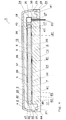
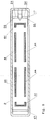
- the Figure 1 shows schematically a longitudinal section through a component 1 according to the invention along the line II of FIG Figure 3 .
- the component 1 is designed as a decorative strip.
- the component 1 according to the invention comprises a flat decorative element 2 with a visible side 3 and a rear side 4.
- the flat decorative element 2 is made, for example, from an opaque metal or from an opaque plastic or from a translucent, in particular transparent, plastic. That the decorative element 2 is "flat" means, as in FIG Figures 1 and 3 It can be seen that the decorative element 2 is substantially larger, in particular by a multiple larger, dimensioned along two dimensions than along a third dimension, which extends perpendicular to the surface area of the visible side 3 of the decorative element 2.
- the flat decorative element 2 is, as in the Figures 1 and 3 can be seen, formed as a band.
- the flat decorative element 2 has a first opening 11 and a second opening 12 ( Figure 1 ).
- the opening 11, seen in the top view of the visible side 3 of the flat decorative element 2 forms a letter E
- the opening 12, when seen in the top view of the visible side 3 of the flat decorative element 2 forms a letter C.
- the specified number of Breakthroughs and the two letters given are only examples.
- the flat decorative element 2 can have at least one opening which forms at least one symbol, such as a letter.
- a single layer 5 with a front side 6 and a rear side 7 is arranged on the rear side 4 of the flat decorative element 2.
- the layer 5 is preferably made from a translucent, in particular transparent, first material, the front side 6 of the layer 5 facing the rear side 4 of the flat decorative element 2.
- a translucent, in particular transparent, film 13 which is attached to the rear side 4 of the flat decorative element 2 and which engages in the openings 11 and 12.
- the slide 13 closes, as in Figure 1 can be seen, flush with the visible side 3 of the flat decorative element 2 and thus prevents soiling, such as solids or liquids, from passing through the openings 11 and 12 of the flat decorative element 2 can get into component 1.
- the film 13 can, if desired, be designed as a diffuser.
- Layer 5 is as in Figure 1 can be seen, attached to the rear side 4 of the flat decorative element 2 and the film 13 and engages in the film 13 below the openings 11 and 12.
- the layer 5, as an alternative to the film 13, or in addition to the film 13, can be designed as a diffuser.
- a lighting module 18 is, as in FIG Figure 1 recognizable, completely embedded in the layer 5.
- the layer 5 is preferably produced by means of a casting process, more preferably by means of an injection molding process.
- the lighting module 18 comprises a carrier 19 designed as a circuit board with a front side 21 and a rear side 60, lighting means 20 designed as a light-emitting diode, which are arranged on the front side 21 of the carrier 19, and a power transmission element 22, which comprises two connection cables, for supplying the lighting means 20 with electricity. If necessary, the lighting module 20 also includes electronics.
- Each of the two connection cables mentioned extends through a passage 23 arranged in the layer 5, the material of the layer 5 lying directly against the connection cables in a sealing manner.
- the illuminants 20 emit light, the light propagates within the layer 5 and leaves the component 1 via the film 13 and the openings 11 and 12 or is emitted from a visible side 15 of the component 1 or from the visible side 3 of the flat decorative element 2 .
- the component 1 has a housing 8 with an inner side 9 and an outer side 10, the inner side 9 of the housing 8 facing the rear side 7 of the layer 5.
- the housing 8 forms, as in Figure 1 recognizable, a rear wall 62, a rear side 63 and a circumferential side wall 64 of the component 1.
- the film 13 thus forms the visible side 15 of the component 1 together with the visible side 3 of the flat decorative element 2 and a partial area 14 of the outer side 10 of the housing 8 Figure 1
- the housing 8 forms a rear side 57 of the component 1, which is opposite the visible side 15 of the component 1.
- the housing 8 is preferably made of an opaque second material.
- a gap 24, in particular an air-filled gap 24, is arranged between the rear side 7 of the layer 5 and the inside 9 of the housing 8, which enables light emitted by the lighting means 20 to be propagated within the layer 5, in particular by total reflection.
- the housing 8 is tightly attached to a circumferential end face 25 of the flat decorative element 2, so that no contamination, such as solids or liquids, can enter the component 1 between the flat decorative element 2 and the housing 8.
- the housing 8 is fastened to the layer 5 in that the housing 8 engages in a recess 26 arranged in the layer 5 via a sealing element 17, which is directed towards the rear side 7 of the layer 5 and designed as an elevation and has a parabolic cross-section.
- a sealing element 17 which is directed towards the rear side 7 of the layer 5 and designed as an elevation and has a parabolic cross-section.
- the inner side 9 of the housing 8, the rear side 7 of the layer 5 and the rear side 4 of the flat decorative element 2 together form a closed space 59.
- the space 59 thus forms a part of the gap 24.
- the sealing element 17 is circular when viewed from above.
- the housing 8 has a base body 31 and the sealing element 17, the base body 31 and the sealing element 17 of the housing 8 being connected to one another in one piece.
- the base body 31 and the sealing element 17 are thus made from the same material.
- the housing 8 can, for example, also be designed in two pieces.
- the base body 31 is made of a material which is different from the material from which the sealing element 17 is made.
- the base body 31 and the sealing element 17 can also be made of the same material.
- the base body 31 is, for example, materially connected to the sealing element 17.
- the component 1 has at least two fastening elements 32 which are integrally connected to the base body 31 of the housing 8.
- the fastening elements 32 serve to fasten the component 1 to a surface (not shown), for example a vehicle.
- a component of the component 1, comprising the housing 8, having the base body 31 and the sealing element 17, as well as the fastening elements 32, can be produced in a particularly simple and cost-effective manner.
- the current transmission element 22 extending through the layer 5 also extends, as in FIG Figure 1 recognizable, through an opening 27 of the housing 8 therethrough.
- the inside 9 of the housing 8, or the sealing element 17, forms a Inlet opening 28 of the opening 27.
- the outlet opening 29 of the opening 27, via which the current transmission element 22 leaves the component 1, is formed by the outside 10 of the housing 8.
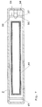
- the Figure 2 shows a cross section of the two connection cables which together form the current transmission element 22 and which protrude into the opening 27.
- the housing 8 is made, for example, of plastic, metal, glass or ceramic.
- the housing 8 is preferably made of plastic.
- the plastic preferably comprises at least one thermoplastic and / or at least one thermoset, more preferably at least one thermoplastic.
- the thermoplastic is, for example, acrylonitrile butadiene styrene (ABS), polyamide (PA), polymethyl methacrylate (PMMA), polycarbonate (PC), polyethylene terephthalate (PET), polyethylene (PE), polypropylene (PP), polystyrene (PS), polyether ether ketone ( PEEK) or polyvinyl chloride (PVC).
- the housing 8 is made of a plastic which comprises at least one thermoplastic, the hardness of the housing 8, or the hardness of the material from which the housing 8 is made, is preferred according to the standard DIN EN ISO 2039-1 from June Measured in 2003. If the housing 8 is made of a plastic which comprises at least one thermoplastic, the housing 8 preferably has a ball indentation hardness in the range of 10-200 N / mm 2 measured in accordance with the standard DIN EN ISO 2039-1 from June 2003 Material from which the housing 8 is made, such as plastic, for example, can, if necessary, also contain additives, such as reinforcing materials, as required.
- the layer 5 is made, for example, of plastic or glass, preferably of plastic.
- the plastic preferably comprises at least one thermoplastic and / or at least one thermoset and / or at least one elastomer, more preferably at least one thermoplastic and / or at least one elastomer, even more preferably at least one elastomer.
- the thermoplastic is, for example, acrylonitrile butadiene styrene (ABS), polyamide (PA), polymethyl methacrylate (PMMA), in particular a PMMA block copolymer, polycarbonate (PC), polyethylene terephthalate (PET), polyethylene (PE), polypropylene (PP) , Polystyrene (PS), polyetheretherketone (PEEK) or polyvinylchloride (PVC).
- the elastomer is, for example, silicone, in particular silicone rubber. Layer 5, if this is made of plastic or glass, for example, it may contain additives, if desired.
- the layer 5 is made of plastic and the plastic comprises at least one thermoplastic and / or at least one thermosetting plastic, preferably at least one thermoplastic
- the hardness of the plastic of the layer 5 is preferably measured in accordance with the DIN EN ISO 2039-1 standard of June 2003.
- the plastic of layer 5, comprising at least one thermoplastic and / or at least one thermoset, preferably comprising at least one thermoplastic preferably has a ball indentation hardness measured in accordance with the standard DIN EN ISO 2039-1 of June 2003 in the range of 10-200 N / mm 2 on.
- the layer 5 is made of plastic and the plastic comprises at least one elastomer, preferably silicone, more preferably silicone rubber
- the hardness of the plastic of the layer 5 is preferably measured in accordance with the DIN ISO 7619-1 standard of February 2012.
- the plastic, comprising at least one elastomer, of the layer 5 preferably has a Shore A hardness, measured in accordance with the DIN ISO 7619-1 standard of February 2012, in the range of 5-90.
- the material from which the housing 8 is made has a hardness which is preferably greater than the hardness of the material from which the layer 5 is made.
- the sealing element 17 of the housing 8 in the layer 5 a circular recess 26 is generated, in which the circular sealing element 17 engages at the same time or during the joining process.
- the material of the layer 5 is preferably displaced and / or compressed and / or deformed, in particular elastically deformed, by the material of the housing 8. In this way, the housing 8 and the layer 5 are securely fastened to one another.
- the housing 8 and the layer 5 are fastened to one another particularly well if the material of the layer 5 is deformed, in particular elastically deformed, by the material of the housing 8.
- the material of the layer 5 clings particularly well to the material of the housing 8, or to a surface 30 of a section 33 of the sealing element 17, which is in the Recess 26 engages, and thus the shape of the engaging section 33 of the sealing element 17 corresponds to the shape of the recess 26.
- the engagement of the circular sealing element 17 in the layer 5, the nestling of the layer 5 on the housing 8 and the fact that the sealing element 17 forms the inlet opening 28 of the opening 27 has the advantage that any contamination, such as solids or liquids, over the opening 27 of the housing 8 cannot get into the space 59 and thus cannot impair the functionality of the component 1, in particular the light conduction within the layer 5.
- the component 1 is more stable and a relative movement of the layer 5 with respect to the housing 8, or a relative movement of the housing 8 with respect to the layer 5, is therefore prevented. This arrangement thus reduces the risk of the component 1 generating rattling noises and thus the component 1 has lower noise emissions.
- the functional reliability of the component 1 is further increased due to the fact that the lighting module 18 is completely embedded in the layer 5.
- the component 1 is simple and inexpensive to manufacture due to its structure.
- the susceptibility of the component 1 to soiling, such as solids or liquids, for example, can be further reduced in that the material of the housing 8 is in direct sealing contact with a section of the current transmission element 22 which extends through the housing 8.
- the gap 24, or the height S of the gap 24, and thus also the height of the space 59 can be set in a defined manner.
- This defined setting of the gap 24, or this defined setting of the space 59 is particularly advantageous if the layer 5 is provided for guiding light and is thus made of a translucent, in particular transparent, material.
- the height S is, for example, in the range from 0.01 to 0.1 millimeters.
- the height S of the gap 24 means the extent of the gap 24 along the direction perpendicular to the inside 9 of the housing 8.
- the layer 5 has, for example, a thickness D in the range from 0.5 millimeters to 3 millimeters, preferably in the range from 0.5 millimeters to 2.6 millimeters.
- the sealing element 17 has, for example, a height H in the range from 0.2 millimeters to 0.4 millimeters.
- the thickness D of the layer 5 means the extension of the thickness D along the direction perpendicular to the rear side 7 of the layer 5.
- the height H of the sealing element 17 means the extent of the height H along the direction perpendicular to the inside 9 of the housing 8.
- the dimensions “thickness D”, “height H”, “height S” and the ratios of the dimensions “thickness D”, “height H”, “height S” to one another are selected.
- the component 1 can be produced, for example, as follows: In a first step, the flat decorative element 2 is provided and provided with the openings 11 and 12, for example by means of punching or laser. The flat decorative element 2 provided with the openings 11 and 12 is then preformed, for example by means of a deep-drawing process. The film 13 is then attached to the rear side 4 of the preformed, flat decorative element 2 provided with the openings 11 and 12, for example by means of an adhesive. Then the flat decorative element 2 provided with the film 13 is inserted into a casting tool (not shown), in particular an injection molding tool, and the lighting module 18 is arranged and fixed behind the film 13 or below the film 13, so that in the subsequent casting process of the layer 5 the Lighting module 18 is not shifted by the casting pressure.
- a casting tool not shown
- the lighting module 18 is arranged and fixed behind the film 13 or below the film 13, so that in the subsequent casting process of the layer 5 the Lighting module 18 is not shifted by the casting pressure.
- the rear side 4 of the flat decorative element 2 and the film 13 are now, for example, back-cast with a translucent, preferably transparent, plastic, in particular back-molded, so that on the one hand a partial area of the film 13 is pressed into the openings 11 and 12 and, on the other hand, the lighting module 18 is completely in which the plastic forming the layer 5 is embedded, so that only the current transmission element 22, comprising two connection cables, protrudes from the layer 5.
- the flat decorative element 2 can, if desired, be further deformed by the casting pressure. Of course, it is also possible for the flat decorative element 2 to be back-cast while still undeformed and for it to be deformed only when the layer 5 is formed or during back-casting.
- the prefabricated housing 8 is then attached to the end face 25 of the flat decorative element 3.
- the housing 8 is also attached to the flat decorative element 2 by the sealing element 17 of the housing 8 engaging the layer 5.
- the current transmission element 22 is led out of the component 1 that has now been manufactured via the opening 27 in the housing 8.
- the Figure 4 shows schematically a longitudinal section through a first embodiment of a component according to the invention.
- the component 1 according to Figure 4 has a flat decorative element 2 with a visible side 3 and a rear side 4, which is made, for example, of a translucent, in particular transparent, plastic. It is also possible, for example, for the flat decorative element 2 to be made from a translucent metal foil.
- a diffuser 34 with a front side 39 and a rear side 35 is arranged on the rear side 4 of the flat decorative element 2.
- the diffuser 34 is preferably produced by casting, preferably back molding, the rear side 4 of the flat decorative element 2.
- Below the diffuser 34 is a layer 5 with a front side 6 and a rear side 7, which is, for example, plate-shaped.
- the front side 6 of the layer 5 faces the rear side 35 of the diffuser 34.
- a gap 36 which contains air, for example, is present between the front side 6 of the layer 5 and the rear side 35 of the diffuser 34.
- the diffuser 34 has a single circumferential sealing element 40 which is oriented in the direction of the front side 6 of the layer 5 and engages in a single depression in the layer 5. Since the sealing element 40 has a circumferential design, a closed space 37 is present between the front side 6 of the layer 5 and the rear side 35 of the diffuser 34. The closed space 37 thus forms a partial area of the gap 36.
- a preferably opaque housing 8 with an inner side 9 and an outer side 10 is arranged below the layer 5. Between the A gap 24 is arranged on the inside 9 of the housing 8 and the rear side 7 of the layer 5.
- a single, circumferential sealing element 17 of the housing 8 engages in a recess 26 arranged in the layer 5 on the rear side 7 of the layer 5.
- the sealing element 17 thus engages in the layer 5 without interruption along the extent of a circumferential edge region 58 of the layer 5. Since the sealing element 17 has a circumferential design, a closed space 46 is arranged between a rear side 7 of the layer 5 and the inside 9 of the housing 8. The closed space 46 thus forms a partial area of the gap 24.
- the housing 8 in turn engages in a recess 48 of the diffuser 34 via a further circumferential sealing element 41, the housing 8 being fastened to the diffuser 34 by this engagement.
- the housing 8 can, if desired, be attached to a circumferential end face 25 of the flat decorative element 2.
- the layer 5 and the diffuser 34 are made, for example, of silicone, in particular silicone rubber, or PMMA block copolymer. If the layer 5 and the diffuser 34 are made of silicone, in particular silicone rubber, the Shore A hardness of the layer 5 and of the diffuser 34 is preferably measured in accordance with the DIN ISO 7619-1 standard of February 2012. If the layer 5 and the diffuser 34 are made of PMMA block copolymer, the hardness of the material of the layer 5 and of the diffuser 34 is preferably measured in accordance with the standard DIN EN ISO 2039-1 of June 2003.
- the housing 8 is preferably made of a plastic comprising at least one thermoplastic and / or at least one thermosetting plastic, preferably at least one thermoplastic.
- thermosetting plastics for the production of the housing 8 are, for example, epoxies, polyurethanes, phenol-formaldehyde resins or polyesters.
- Translucent thermosetting plastics, such as epoxies or polyesters, for example, can also be used to produce the layer 5 and the diffuser 34.
- the hardness of the material from which the housing 8 is made is preferably measured in accordance with the standard DIN EN ISO 2039-1 of June 2003.
- the material from which the diffuser 34 is made preferably has a Shore A hardness in the range of 5-90.
- the material from which the layer 5 is made preferably has a Shore A hardness in the range of 5-90.
- the material from which the housing 8 is made preferably has a hardness in the range of 10-200 N / mm 2 .
- the material from which the housing 8 is made has a hardness which is greater than the hardness of the material from which the layer 5 and the diffuser 34 are made.
- the material from which the diffuser 34 is made is in turn harder than the material from which the layer 5 is made.
- the silicone material from which the layer 5 is made differs in composition from the silicone material from which the diffuser 34 is made.
- the silicone material from which the diffuser 34 is made is identical to the silicone material from which the layer 5 is made
- the silicone material from which the diffuser 34 is made compared to the silicone material from which the layer 5 is made is, additionally has light-scattering particles, for example.
- the silicone material from which the diffuser 34 is made is cloudy and therefore light-scattering, whereas the silicone material from which the layer 5 is made does not have any light-scattering effect and is therefore clear, in particular crystal clear, for example. is trained.
- the light-scattering effect of the diffuser 34 is thus not produced by, for example, light-scattering particles incorporated in the diffuser 34, but is ensured exclusively by the silicone material from which the diffuser 34 is made.
- the sealing element 40 of the diffuser 34 engages in the material of the layer 5 due to the higher hardness of the material of the diffuser 34 compared to the hardness of the material of the layer 5 a.
- the sealing element 41 of the housing 8 engages in the diffuser 34 and the sealing element 17 of the housing 8 engages in the layer 5.
- This engagement of the housing 8 in the diffuser 34 and the layer 5 takes place because the hardness of the material of the housing 8 compared to the hardness of the material of the layer 5 and of the diffuser 34 is larger.
- the housing 8 is therefore fastened twice by the sealing elements 17, 41.
- the sealing element 40 of the diffuser 34 engages in the material of the layer 5, for example, in that the sealing element 40 displaces the material of the layer 5, for example.
- the engagement of the sealing element 40 in the layer 5 can, however, also take place in that, for example, the sealing element 40 compresses or deforms the material of the layer 5, in particular deforms it elastically.
- the sealing element 17 of the housing 8 engages in the material of the layer 5, for example, in that the sealing element 17 displaces, compresses or deforms the material of the layer 5, for example, in particular deforms it elastically.
- the sealing element 41 of the housing 8 engages, for example, in the material of the diffuser 34 by the sealing element 41 for example displacing, compressing or deforming the material of the diffuser 34, in particular elastically deforming it.
- the luminous means 20, which is designed as a light-emitting diode and is suitable for coupling light into the layer 5, is arranged adjacent to a side surface 38 of the layer 5.
- the light propagates within the layer 5, in particular by total reflection, and leaves the layer 5 due to light deflecting structures 61 arranged on the rear side 7 of the layer 5, defined via a front side 6 of the layer 5, and then becomes via the diffuser 34 and the flat decorative element 2 are radiated from a visible side 15 of the component 1.
- light deflecting structures 61 can also be provided on the front side 6 of the layer 5 (not shown).
- the diffuser 34 has the effect that the light radiated into the diffuser 34 from the layer 5 is radiated out of the diffuser 34 in a uniform manner via a front side 39 of the diffuser 34. No contamination, such as solids or liquids, can enter the closed spaces 37 and 46, and thus optimal light conduction within layer 5 and optimal coupling of light out of layer 5 are guaranteed.
- the engagement of the circumferential sealing element 17 and the circumferential sealing element 41 of the housing 8 in the layer 5, as well as the engagement of the circumferential sealing element 40 of the diffuser 34 in the layer 5, have the advantage that any contamination such as solids or liquids, for example about the breakthrough 27 of the housing 8, into which the closed spaces 24 and 36 of the component 1 can get, and thus, for example, can interfere with the propagation of the light in the layer 5.
- the component 1 is made more stable. Furthermore, the engagement prevents a relative movement of the layer 5 with respect to the housing 8 or a relative movement of the housing 8 with respect to the layer 5, as well as a relative movement of the layer 5 with respect to the diffuser 34 or a relative movement of the diffuser 34 with respect to the layer 5. As a result of the engagement of the sealing elements 17, 40 and 41, the risk of the component 1 generating rattling noises is thus reduced, and the component 1 is therefore lower in noise. In addition, the component 1 can be produced simply and inexpensively, since the layer 5 only has to be plugged onto the diffuser 34 and the housing 8 only needs to be plugged onto the layer 5 and the diffuser 34.
- the gap 24 when the layer 5 and the housing 8 are joined can be set in a defined manner.
- a gap 36 can be created between a rear side 35 of the diffuser 34 when the layer 5 and the diffuser 34 are joined and the front side 6 of the layer 5 can be set in a defined manner. This defined setting of the gap 24 and the gap 36 is particularly advantageous if the layer 5 is provided for guiding light and is thus made from a translucent material, in particular from a transparent material.
- the Figure 5 shows schematically a longitudinal section through a second embodiment of a component according to the invention.
- the component 1 according to Figure 5 has a flat decorative element 2 with a visible side 3 and a rear side 4, which is made, for example, of a translucent, in particular transparent, plastic. It is also possible, for example, for the flat decorative element 2 to be made of a translucent metal foil is made.
- a diffuser 34 with a front side 39 and a rear side 35 is arranged on the rear side 4 of the flat decorative element 2.
- the front side 39 of the diffuser 34 faces the rear side 4 of the flat decorative element 2 and the rear side 35 of the diffuser 34 faces a front side 6 of a first layer 50 which is arranged below the diffuser 34.
- the first layer 50 is made of a translucent, in particular transparent, material and is used to guide light. As in Figure 5 As can be seen, a gap 42 is arranged between the rear side 4 of the flat decorative element 2 and the front side 39 of the diffuser 34 and a gap 36 is present between the rear side 35 of the diffuser 34 and the front side 6 of the first layer 50.
- the first layer 50 has a single, circumferential sealing element 43 which comprises an undercut and, as in FIG Figure 5 can be seen, for example, can be formed mushroom-shaped in cross section. The undercut offers the advantage that the first layer 50 and the diffuser 34 are fastened to one another particularly well.
- the sealing element 43 engages in a recess 49 of the diffuser 34.
- a second layer 45 with a front side 6 and a rear side 7 is arranged below the first layer 50, a gap 65 being present between the front side 6 of the second layer 5 and the rear side 7 of the first layer 50.
- the second layer 45 is in turn made from a translucent, in particular transparent, material and is used to guide light.
- the material of the first layer 50 and the material of the second layer 45 together form a group of first materials.
- Two sealing elements 44 of the second layer 45 which, as in FIG Figure 5 recognizable, for example can be triangular in cross-section, engage in the material of the first layer 50 or in a respective recess 51 of the first layer 50.
- the Figure 6 shows schematically a plan view of a cross section along the line III-III through the component according to FIG Figure 5 . Based on Figure 6 it can be seen that the two sealing elements 44 lie parallel to one another and each extend over part of the width of the first layer 50.
- the second layer 45 can have a single, circumferential sealing element 44 instead of the two sealing elements 44, which in FIG Figure 7 is shown.
- the Figure 7 shows schematically a plan view of a cross section along the line III-III by a first variant of the component 1 according to Figure 5 .
- the first layer 50 can have a plurality of sealing elements 44 spaced apart from one another, which together form a circumferential sealing element with interruptions.
- Said sealing elements 44 are in Figure 8 can be seen which Figure 8 schematically a plan view of a cross section along the line III-III through a second variant of the component 1 according to FIG Figure 5 shows.
- the sealing elements 44 according to the Figures 7 and 8th are each triangular in cross-section.
- the component 1 according to Figure 5 has a housing 8 with an inside 9 and an outside 10.
- the housing 8 is made of a second material, the hardness of which is different from the hardness of the respective first materials.
- the housing 8 comprises the housing 8 of the component 1 according to Figure 5 two sealing elements 17 opposite one another in parallel, which extend over almost the entire width of the housing 8 and closely adjoin the inside 9 of the flat decorative element 2.
- each of the two sealing elements 17 engages in a respective recess 26 in the second layer 45. Seen in cross section, the sealing elements 17 are rectangular.
- the rear side 4 of the flat decorative element 2, the rear side 7 of the second layer 45 and the inside 9 of the housing 8 jointly delimit a closed space 46.
- the housing 8 is attached via the inside 9 to a circumferential end face 25 of the flat decorative element 2.
- the material from which the first layer 50 is made has a greater hardness than the material from which the diffuser 34 is made.
- the material from which the second layer 45 is made in turn, has a greater hardness than the material from which the first layer 50 is made, and the material from which the housing 8 is made, in turn, has a greater hardness than the material from which the second layer 45 is made.
- the diffuser 34, the first layer 50 and the second layer 45 are preferably made from silicone, in particular from silicone rubber.
- the material, such as the silicone from which the diffuser 34, the first layer 50 and the second layer 45 are made preferably has a Shore A hardness in the range of 5-90, which is preferably in accordance with the DIN ISO 7619 standard -1 from February 2012 is measured.
- the composition of the material is such as, for example, the silicone from which the diffuser 34, the first layer 50 and the second layer 45 are made.
- the material from which the housing 8 is made preferably comprises at least one thermoplastic and preferably has a hardness in the range of 10-200 N / mm 2 , which is preferably measured in accordance with the standard DIN EN ISO 2039-1 of June 2003.
- the first layer 50 can engage in the diffuser 34 when the first layer 50 and the diffuser 34 are joined.
- the material of the diffuser 34 is, for example, displaced, compressed or deformed, in particular elastically deformed, by the material of the first layer 50.
- the component 1 has a first luminous means 52, which is designed as a light-emitting diode, the luminous means 52 being arranged adjacent to a side surface 38 of the first layer 50 for coupling light into the first layer 50 a second luminous means 53, which is arranged below the first luminous means 52 and is designed as a light-emitting diode, the luminous means 53 being partially arranged in a recess 16 of the second layer 45. Electric power is supplied to the first illuminant 52 and the second illuminant 53 via a current transmission element 22 of the component 1, which is designed as two connecting cables.
- the sealing element 17 arranged adjacent to the lighting means 52, 53 is arranged below the lighting means 53. This reduces the risk of light coupled into the second layer 45 by the lighting means 53 being disturbed by the sealing element 17 arranged below the lighting means 53 while it is propagating within the second layer 45.
- the sealing element 17 arranged below the second illuminant 53 has an outermost edge 54 and an innermost edge 55, the outermost edge 54 facing the rear side 4 of the flat decorative element 2.
- the second illuminant 53 has a light-emitting surface 56, this surface 56 being used in this way innermost edge 55 is arranged so that the light emitted by the surface 56 is irradiated into a region of the second layer 45 which extends away from the innermost edge 55 in a direction facing away from the outermost edge 54.
- This offers the advantage that the light propagating in the second layer 45 is not disturbed by the sealing element 17 arranged below the illuminant 53.
- the component 1 according to FIG Figure 1 instead of a layer 5 cast onto the rear side 4 of the flat decorative element 2 and the film 13, have a layer 5 'in which a lighting means 20 or a lighting module 18 is completely embedded and which is arranged directly below the film 13, so that A gap, which preferably contains air, is arranged between the layer 5 'and the rear side 4 of the flat decorative element 2 and the film 13. This gap is particularly advantageous if the layer 5 'is provided for guiding light.
- light deflecting structures 61 can be provided on the front side 6 and / or the rear side 7 of the layer 5 ′.
- light deflection structures 61 may also be provided.
- light deflecting structures 61 arranged on the layers 5, 5 ′, 45, 50 mentioned light deflecting structures can also be incorporated into the layers 5, 5 ′, 45, 50, for example. The incorporated light deflecting structures are less prone to damage. A large number of other modifications are possible.
Landscapes
- Physics & Mathematics (AREA)
- Engineering & Computer Science (AREA)
- General Physics & Mathematics (AREA)
- Mechanical Engineering (AREA)
- Optics & Photonics (AREA)
- Theoretical Computer Science (AREA)
- Business, Economics & Management (AREA)
- Accounting & Taxation (AREA)
- Marketing (AREA)
- General Engineering & Computer Science (AREA)
- Manufacturing & Machinery (AREA)
- Casings For Electric Apparatus (AREA)
- Laminated Bodies (AREA)
Description
Die vorliegende Erfindung betrifft ein Bauteil, insbesondere ein Bauteil für ein Fahrzeug.The present invention relates to a component, in particular a component for a vehicle.
Das Dokument
Weitere gattungsgemässe Bauteile sind in der
Es ist also eine Aufgabe der vorliegenden Erfindung ein Bauteil zu schaffen, welches einfacher herstellbar, funktionssicherer und zudem vorteilhaft geräuschemissionsarm ist.It is therefore an object of the present invention to create a component which is easier to manufacture, more reliable and, in addition, is advantageously low in noise.
Zur Lösung dieser Aufgabe wird ein Bauteil vorgeschlagen, wie dieses in Anspruch 1 angegeben ist.To solve this problem, a component as specified in
Die vorliegende Erfindung stellt also ein Bauteil zur Verfügung umfassend
- ein flächiges Dekorelement mit einer Sichtseite und einer Rückseite,
- eine aus einem ersten Material hergestellte Schicht oder mehrere aus ersten Materialien hergestellte Schichten, wobei die eine oder mehreren Schichten jeweils an der Rückseite des flächigen Dekorelementes angeordnet sind und jeweils eine Vorderseite und eine Hinterseite aufweisen, wobei die Vorderseite jeweils der Rückseite des flächigen Dekorelementes zugewandt ist, sowie
- ein aus einem zweiten Material hergestelltes Gehäuse mit einer Innenseite und einer Aussenseite, wobei die Innenseite den jeweiligen Hinterseiten der einen oder mehreren Schichten zugewandt ist,
und wobei das Gehäuse in wenigstens eine Vertiefung eingreift, die zumindest in einer der einen oder mehreren Schichten angeordnet ist.The present invention thus provides a component comprehensively
- a flat decorative element with a visible side and a rear side,
- a layer produced from a first material or a plurality of layers produced from first materials, the one or more layers in each case being an the rear side of the flat decorative element are arranged and each have a front side and a rear side, the front side in each case facing the rear side of the flat decorative element, and
- a housing made of a second material with an inside and an outside, the inside facing the respective rear sides of the one or more layers,
and wherein the housing engages in at least one recess which is arranged in at least one of the one or more layers.
Das Bauteil umfasst ausserdem wenigstens ein Leuchtmittel zur Einkopplung von Licht in wenigstens eine der wenigstens einen Schicht sowie wenigstens ein Stromübertragungselement, welches beispielsweise als wenigstens ein Anschlusskabel ausgebildet ist, zur Versorgung des Leuchtmittels mit elektrischem Strom. Bevorzugt ist das Leuchtmittel als punktförmiges Leuchtmittel ausgebildet. Dieses punktförmige Leuchtmittel ist beispielsweise eine Leuchtdiode. Das Leuchtmittel kann aber beispielsweise auch als Elektrolumineszenzfolie, OLED oder Glühbirne ausgebildet sein. Bevorzugt ist wenigstens ein Leuchtmittel, welches vorzugsweise als Leuchtdiode ausgebildet ist, auf einem Träger, beispielsweise auf einer Platine, befestigt. Bevorzugt bildet das Leuchtmittel mit dem Träger, dem Stromübertragungselement zur Versorgung des Leuchtmittels mit elektrischem Strom, sowie gegebenenfalls mit einer Elektronik, ein Beleuchtungsmodul.The component also comprises at least one illuminant for coupling light into at least one of the at least one layer and at least one power transmission element, which is designed, for example, as at least one connection cable, for supplying the illuminant with electrical current. The illuminant is preferably designed as a point-shaped illuminant. This point-shaped illuminant is, for example, a light-emitting diode. The lighting means can, however, also be designed as an electroluminescent film, OLED or light bulb, for example. At least one lighting means, which is preferably designed as a light-emitting diode, is preferably fastened on a carrier, for example on a circuit board. The illuminant preferably forms a lighting module with the carrier, the power transmission element for supplying the illuminant with electrical power, and optionally with electronics.
Das Gehäuse weist zudem wenigstens einen Durchbruch auf, wobei die Innenseite des Gehäuses eine Eingangsöffnung des Durchbruches und die Aussenseite des Gehäuses eine Ausgangsöffnung des Durchbruches bildet. Das Stromübertragungselement erstreckt sich wenigstens durch den Durchbruch hindurch von der Innenseite zur Aussenseite des Gehäuses. Bevorzugt liegt das Material des Gehäuses unmittelbar dichtend an einem Abschnitt des Stromübertragungselementes an, welcher im Durchbruch angeordnet ist. Dies bewirkt den Vorteil, dass durch den Durchbruch keine Verschmutzungen, wie beispielsweise Flüssigkeiten oder Feststoffe, in das Bauteil gelangen können. Das Gehäuse weist auf der Innenseite wenigstens ein in Richtung der Hinterseite der Schicht gerichtetes Element in Form eines Dichtelements auf, welches in wenigstens eine in der Schicht angeordnete Vertiefung eingreift und welches die Eingangsöffnung des Durchbruches wenigstens teilweise, bevorzugt vollständig, bildet. Dies bietet den Vorteil, dass allfällige in den Durchbruch gelangende Verschmutzungen, wie Flüssigkeiten oder Feststoffe, insbesondere nicht zwischen die Hinterseite der Schicht und der Innenseite des Gehäuses gelangen können. Bevorzugt ist das Dichtelement unterhalb des Leuchtmittels oder des Beleuchtungsmoduls angeordnet. Dies bietet den Vorteil, dass das Risiko, dass das Dichtelement des Gehäuses, welches in die in der Schicht angeordnete Vertiefung eingreift, allfälliges sich innerhalb der Schicht fortpflanzendes Licht stört, vermindert ist. Weist beispielsweise das Bauteil einen Träger, wie beispielsweise eine Platine, mit einer Vorderseite und einer Rückseite auf, wobei die Vorderseite des Trägers der Rückseite des flächigen Dekorelementes zugewandt und wobei das Leuchtmittel auf der Vorderseite des Trägers angeordnet ist, so ist das Dichtelement bevorzugt im Bereich der Rückseite des Trägers sowie bevorzugt unterhalb der Rückseite des Trägers angeordnet. Die Gefahr, dass allfälliges vom Leuchtmittel oder vom Beleuchtungsmodul in die Schicht eingekoppeltes Licht durch das Dichtelement, welches in die Schicht eingreift, bei dessen Fortpflanzung in der Schicht gestört wird, ist vermindert.The housing also has at least one opening, the inside of the housing forming an inlet opening of the opening and the outside of the housing forming an outlet opening of the opening. The current transmission element extends at least through the opening from the inside to the outside of the housing. The material of the housing is preferably in direct sealing contact with a section of the current transmission element which is arranged in the opening. This has the advantage that no contamination, such as liquids or solids, can get into the component through the breakthrough. On the inside, the housing has at least one element directed in the direction of the rear side of the layer in the form of a sealing element which engages in at least one recess arranged in the layer and which at least partially, preferably completely, forms the inlet opening of the opening. This offers the advantage that any contamination that gets into the opening, such as liquids or solids, in particular cannot get between the back of the layer and the inside of the housing. The sealing element is preferably arranged below the lighting means or the lighting module. This offers the advantage that the risk of the sealing element of the housing, which engages in the recess arranged in the layer, interfering with any light propagating within the layer, is reduced. If, for example, the component has a carrier, such as a circuit board, with a front side and a rear side, the front side of the carrier facing the rear side of the flat decorative element and the lighting means being arranged on the front side of the carrier, the sealing element is preferably in the area the back of the carrier and preferably arranged below the back of the carrier. The risk that any light coupled into the layer by the lighting means or the lighting module is reduced by the sealing element which engages in the layer and its propagation in the layer is disturbed.
Da das Gehäuse in wenigstens eine in zumindest einer der einen oder mehreren Schichten angeordnete Vertiefung eingreift, wird die Gefahr vermindert, dass die entsprechende zumindest eine Schicht sich relativ zum Gehäuse bewegen kann, bzw. dass das Gehäuse sich relativ zur entsprechenden Schicht bewegen kann. Durch diese Verbindung von Gehäuse und der zumindest einen Schicht ist das Bauteil einfacher herstellbar und bevorzugt gleichzeitig geräuschemissionsarm. Des Weiteren sind die Schicht und das Gehäuse auf diese Weise gut aneinander befestigbar. Aufgrund des Eingriffs der zumindest einen Schicht in das Gehäuse bzw. des Gehäuses in die zumindest eine Schicht wird zudem die Gefahr vermindert, dass Verschmutzungen, wie beispielsweise Flüssigkeiten oder Feststoffe, zwischen die Schicht und das Gehäuse gelangen können. Sind das Gehäuse und die Schicht gefügt, so können sich das Gehäuse und die Schicht in dem oder den Bereichen des gegenseitigen Eingriffs, aufgrund der unterschiedlichen Härten, besonders gut aneinander anschmiegen. Dadurch wird die Gefahr von Relativbewegungen zwischen dem Gehäuse und der entsprechenden Schicht weiter verringert, und es wird zudem eine besonders gute wenigstens teilweise Abdichtung eines allfälligen Raumes beziehungsweise Spaltes möglich, welcher zwischen der Innenseite des Gehäuses und der Hinterseite der Schicht angeordnet ist. Das erfindungsgemässe Bauteil ist somit verschmutzungssicherer und somit funktionssicherer als Bauteile des Standes der Technik.Since the housing engages in at least one recess arranged in at least one of the one or more layers, the risk is reduced that the corresponding at least one layer can move relative to the housing or that the housing can move relative to the corresponding layer. This connection of the housing and the at least one layer makes the component easier to manufacture and preferably at the same time low in noise. Furthermore, the layer and the housing can be easily attached to one another in this way. Due to the engagement of the at least one layer in the housing or of the housing in the at least one layer, the risk is also reduced that contaminants, such as liquids or solids, can get between the layer and the housing. If the housing and the layer are joined, the housing and the layer in the area or areas of mutual engagement, due to the different hardnesses, cling to one another particularly well. This further reduces the risk of relative movements between the housing and the corresponding layer, and a particularly good at least partial sealing of any space or gap that is arranged between the inside of the housing and the rear of the layer is also possible. The component according to the invention is thus more pollution-proof and thus more reliable than components of the prior art.
Bevorzugt greift das Gehäuse in jede der einen oder mehreren Schichten ein, das heisst in jeder der Schichten ist wenigstens eine Vertiefung vorgesehen. Es kann aber auch nur eine einzelne oder eine gewisse Anzahl der einen oder mehreren Schichten in Eingriff mit dem Gehäuse stehen.The housing preferably engages in each of the one or more layers, that is to say at least one recess is provided in each of the layers. It however, only a single layer or a certain number of the one or more layers can be in engagement with the housing.
Wenn im Folgenden jeweils von "einer Schicht" oder von "der Schicht" die Rede ist, dann ist damit der Einfachheit halber, sofern nichts anderes angegeben ist, bevorzugt jeweils eine beliebige der einen oder mehreren Schichten gemeint. Bevorzugter ist jedoch eine Schicht der einen oder mehreren Schichten gemeint, welche in Eingriff mit dem Gehäuse steht. Noch bevorzugter sind alle Schichten der einen oder mehreren Schichten gemeint, welche in Eingriff mit dem Gehäuse stehen. Am bevorzugtesten sind jedoch sogar alle der einen oder mehreren Schichten gemeint. Die Ausdrücke "eine Schicht" und "die Schicht" können im Folgenden somit jeweils sowohl eine einzige Schicht als auch mehrere Schichten betreffen. Dasselbe gilt sinngemäss für die mit der Schicht in direktem Zusammenhang stehenden Ausdrücke, wie insbesondere "das erste Material", "die Vorderseite" und "die Hinterseite", welche je nachdem, ob eine einzige oder mehrere Schichten betroffen sind, entsprechend in der Einzahl oder in der Mehrzahl verstanden werden können.Whenever "a layer" or "the layer" is used in the following, for the sake of simplicity, unless otherwise specified, any one of the one or more layers is preferably meant. More preferably, however, is meant a layer of the one or more layers which is in engagement with the housing. Even more preferably, all layers of the one or more layers are meant which are in engagement with the housing. Most preferably, however, even all of the one or more layers are meant. The expressions “a layer” and “the layer” can thus in the following each relate to a single layer as well as to a plurality of layers. The same applies mutatis mutandis to expressions that are directly related to the layer, such as in particular "the first material", "the front side" and "the rear side", which, depending on whether a single layer or several layers are concerned, correspondingly in the singular or can be understood in the plural.
Das Merkmal, dass das Dekorelement flächig ausgebildet ist, bedeutet, dass das Dekorelement entlang von zwei Dimensionen wesentlich grösser, insbesondere um ein Vielfaches grösser, dimensioniert ist als entlang einer dritten Dimension, welche sich in der Regel senkrecht zur Flächenausdehnung der Sichtseite des Dekorelementes erstreckt. Das flächige Dekorelement ist beispielsweise bandförmig, insbesondere als Band, ausgebildet.The feature that the decorative element has a flat design means that the decorative element is dimensioned substantially larger, in particular many times larger, along two dimensions than along a third dimension, which generally extends perpendicular to the surface area of the visible side of the decorative element. The flat decorative element is, for example, in the form of a band, in particular as a band.
Orts- und Richtungsangaben wie oben, unten, vertikal, horizontal, nach oben und nach unten sind im Folgenden jeweils in Bezug auf die Sichtseite des Bauteils zu verstehen. Dabei ist üblicherweise die Sichtseite des Bauteils oben und eine Rückseite des Bauteils unten angeordnet. In welcher Lage und Position das Bauteil in Bezug auf die Schwerkraftrichtung tatsächlich, wie zum Beispiel in einem Fahrzeug, montiert ist, ist hierbei unerheblich.Location and direction information such as up, down, vertical, horizontal, up and down are to be understood in the following in relation to the visible side of the component. The visible side of the component is usually arranged at the top and a rear side of the component is arranged at the bottom. The position and position in which the component is actually mounted in relation to the direction of gravity, such as in a vehicle, is irrelevant here.
Nach einer Weiterbildung der Erfindung weist das Gehäuse wenigstens ein Element, welches als Dichtelement ausgebildet ist, auf, über welches das Gehäuse in wenigstens eine in der Schicht angeordnete Vertiefung eingreift. Das Element ist bevorzugt als Erhebung ausgebildet. Das Element ist im Querschnitt beispielsweise quadratisch, dreieckförmig oder in einer beliebig anderen Form ausgebildet. Bevorzugt weist das Element einen Hinterschnitt auf. Dies bietet den Vorteil, dass die Schicht und das Gehäuse besonders gut aneinander befestigt sind. Bevorzugt schmiegt sich das Material der Schicht an wenigstens einen Teilbereich einer Oberfläche des Elementes an, so dass eine gute wenigstens teilweise Abdichtung eines allfälligen zwischen der Hinterseite der Schicht sowie der Innenseite des Gehäuses angeordneten Raumes beziehungsweise Spaltes möglich ist. Besonders bevorzugt korrespondiert die Form wenigstens eines Abschnittes des Elementes mit der Form der Vertiefung in welche der Abschnitt des Elementes eingreift. Hierdurch ist eine besonders gute wenigstens teilweise Abdichtung eines allfälligen zwischen der Hinterseite der Schicht sowie der Innenseite des Gehäuses angeordneten Raumes beziehungsweise Spaltes möglich. Bevorzugt weist das Gehäuse einen Grundkörper sowie das wenigstens eine Element auf, wobei bevorzugt der Grundkörper mit dem Element einstückig verbunden ist. Der Grundkörper und das Element des Gehäuses können beispielsweise auch zweistückig ausgebildet sein, wobei das Element beispielsweise stoffschlüssig mit dem Grundkörper verbunden ist.According to a further development of the invention, the housing has at least one element, which is designed as a sealing element, via which the housing engages in at least one recess arranged in the layer. The element is preferred as Elevation trained. The element is, for example, square, triangular or any other shape in cross section. The element preferably has an undercut. This offers the advantage that the layer and the housing are fastened to one another particularly well. The material of the layer preferably hugs at least a partial area of a surface of the element so that a good at least partial sealing of any space or gap arranged between the rear side of the layer and the inside of the housing is possible. Particularly preferably, the shape of at least one section of the element corresponds to the shape of the recess in which the section of the element engages. This enables particularly good, at least partial, sealing of any space or gap arranged between the rear side of the layer and the inside of the housing. The housing preferably has a base body and the at least one element, the base body preferably being connected in one piece to the element. The base body and the element of the housing can, for example, also be designed in two parts, the element being, for example, materially connected to the base body.
Nach einer Weiterbildung der Erfindung weist das zweite Material, aus welchem das Gehäuse hergestellt ist, eine Härte auf, welche grösser als die Härte des oder der ersten Materialien ist. Das oder die ersten Materialien weisen somit bevorzugt Härten auf, welche jeweils kleiner als die Härte des zweiten Materiales sind. In Bezug auf das Eingreifen des Gehäuses in die Schicht ergeben sich hierdurch wenigstens zwei Varianten:
Gemäss einer ersten, bevorzugten Variante wird die wenigstens eine Vertiefung, aufgrund der grösseren Härte des Gehäuses im Vergleich zur Härte der Schicht, beim Fügen des Gehäuses und der Schicht durch das Gehäuse in der Schicht generiert. Das Gehäuse greift dann während des Fügevorganges gleichzeitig in die Schicht ein. Beim Fügen der Schicht und dem Gehäuse wird somit das erste Material der Schicht durch das zweite Material des Gehäuses verdrängt und / oder verdichtet und / oder verformt, bevorzugt elastisch verformt, und hierdurch die Vertiefung in der Schicht generiert. Sind das Gehäuse und die Schicht gefügt, so schmiegt sich die Schicht, aufgrund deren geringeren Härte im Vergleich zur Härte des Gehäuses, besonders gut an das in die Vertiefung der Schicht eingreifende Gehäuse an und somit wird eine besonders gute wenigstens teilweise Abdichtung eines allfälligen Raumes beziehungsweise Spaltes möglich, welcher zwischen der Innenseite des Gehäuses und der Hinterseite der Schicht angeordnet ist. Zudem werden hierdurch das Gehäuse und die Schicht besonders gut aneinander befestigt. Eine besonders gute Abdichtung sowie Befestigung ist erzielbar, falls das Material der Schicht durch das Material des Gehäuses verformt, insbesondere elastisch verformt wird.According to a further development of the invention, the second material from which the housing is made has a hardness which is greater than the hardness of the first material or materials. The first material or materials thus preferably have hardnesses which are each less than the hardness of the second material. With regard to the engagement of the housing in the layer, this results in at least two variants:
According to a first, preferred variant, due to the greater hardness of the housing compared to the hardness of the layer, the at least one depression is generated in the layer when the housing and the layer are joined by the housing. The housing then engages in the layer at the same time during the joining process. When the layer and the housing are joined, the first material of the layer is thus displaced and / or compressed and / or deformed, preferably elastically deformed, by the second material of the housing, and the recess is thereby generated in the layer. If the housing and the layer are joined, the layer, due to its lower hardness compared to the hardness of the housing, clings particularly well to the housing engaging in the recess of the layer and thus a particularly good at least partial seal of any space or area Gap possible, which is arranged between the inside of the housing and the rear side of the layer. In addition, the housing and the layer are particularly well attached to one another as a result. Particularly good sealing and fastening can be achieved if the material of the layer is deformed, in particular elastically, by the material of the housing.
Gemäss einer zweiten Variante weist die Schicht bereits wenigstens eine vorgefertigte Vertiefung auf. Beim Fügen der Schicht und dem Gehäuse greift somit bei dieser zweiten Variante das Gehäuse in wenigstens eine in der Schicht bereits angeordnete, vorgefertigte Vertiefung ein. Es entsteht somit beim Fügen der Schicht und dem Gehäuse keine Vertiefung.According to a second variant, the layer already has at least one prefabricated depression. When the layer and the housing are joined, in this second variant the housing engages in at least one prefabricated recess already arranged in the layer. There is thus no recess when the layer and the housing are joined.
Selbstverständlich kann auch bei der zweiten Variante das erste Material der Schicht durch das zweite Material des Gehäuses zusätzlich noch verdrängt und / oder verdichtet und / oder verformt, bevorzugt elastisch verformt werden oder bei der ersten, bevorzugten Variante die Schicht zusätzlich wenigstens eine vorgefertigte Vertiefung aufweisen. Das Gehäuse und die Schicht können bei der zweiten Variante sowie der ersten, bevorzugten Variante über wenigstens eine vorgefertigte Vertiefung sowie über wenigstens eine während des Fügens generierte Vertiefung miteinander verbunden sein.Of course, in the second variant too, the first material of the layer can additionally be displaced and / or compressed and / or deformed, preferably elastically deformed, by the second material of the housing, or in the first, preferred variant, the layer can additionally have at least one prefabricated recess. In the case of the second variant and the first, preferred variant, the housing and the layer can be connected to one another via at least one prefabricated recess and via at least one recess generated during the joining.
Nach einer Weiterbildung der Erfindung ist die wenigstens eine Vertiefung eine vorgefertigte Vertiefung.According to a further development of the invention, the at least one depression is a prefabricated depression.
Nach einer Weiterbildung der Erfindung ist das erste Material, aus welchem die Schicht hergestellt ist, durch das zweite Material, aus welchem das Gehäuse hergestellt ist, verdrängbar.According to a further development of the invention, the first material from which the layer is made can be displaced by the second material from which the housing is made.
Nach einer Weiterbildung der Erfindung ist das erste Material, aus welchem die Schicht hergestellt ist, durch das zweite Material, aus welchem das Gehäuse hergestellt ist, verdichtbar.According to a further development of the invention, the first material from which the layer is made can be compressed by the second material from which the housing is made.
Nach einer Weiterbildung der Erfindung ist das erste Material, aus welchem die Schicht hergestellt ist, durch das zweite Material, aus welchem das Gehäuse hergestellt ist, verformbar, insbesondere elastisch verformbar.According to a further development of the invention, the first material from which the layer is made can be deformed, in particular elastically deformable, by the second material from which the housing is made.
Falls das erste Material, aus welchem die Schicht hergestellt ist, durch das zweite Material, aus welchem das Gehäuse hergestellt ist, verdrängbar und / oder verdichtbar und / oder verformbar, insbesondere elastisch verformbar, ist, so kann durch die Auswahl der Härte des ersten Materiales, aus welchem die Schicht hergestellt ist, relativ zur Härte des zweiten Materiales, aus welchem das Gehäuse hergestellt ist, beim Fügen der Schicht und des Gehäuses, bei welchem das Gehäuse in die Schicht eingreift, ein definierter Spalt, welcher bevorzugt Luft enthält, zwischen der Hinterseite der Schicht und der Innenseite des Gehäuses eingestellt werden. Diese definierte Einstellung ist insbesondere vorteilhaft, falls die Schicht insbesondere zur Lichtleitung vorgesehen ist und somit aus einem transluzenten Material, insbesondere transparenten Material, hergestellt ist.If the first material from which the layer is made is displaceable and / or compressible and / or deformable, in particular elastically deformable, by the second material from which the housing is made, then the selection of the hardness of the first material , from which the layer is made, relative to the hardness of the second material from which the housing is made, when joining the layer and the housing in which the housing engages the layer, a defined gap, which preferably contains air, between the Rear side of the layer and the inside of the housing can be adjusted. This defined setting is particularly advantageous if the layer is provided in particular for guiding light and is thus made of a translucent material, in particular a transparent material.
Nach einer Weiterbildung der Erfindung weist das erste Material, aus welchem die Schicht hergestellt ist, eine Härte auf, welche grösser als die Härte des zweiten Materiales ist, aus welchem das Gehäuse hergestellt ist.According to a further development of the invention, the first material from which the layer is made has a hardness which is greater than the hardness of the second material from which the housing is made.
Nach einer Weiterbildung der Erfindung ist das zweite Material, aus welchem das Gehäuse hergestellt ist, durch das erste Material, aus welchem die Schicht hergestellt ist, verdrängbar.According to a further development of the invention, the second material from which the housing is made can be displaced by the first material from which the layer is made.
Nach einer Weiterbildung der Erfindung ist das zweite Material, aus welchem das Gehäuse hergestellt ist, durch das erste Material, aus welchem die Schicht hergestellt ist, verdichtbar.According to a further development of the invention, the second material from which the housing is made can be compressed by the first material from which the layer is made.
Nach einer Weiterbildung der Erfindung ist das zweite Material, aus welchem das Gehäuse hergestellt ist, durch das erste Material, aus welchem die Schicht hergestellt ist, verformbar, insbesondere elastisch verformbar.According to a further development of the invention, the second material from which the housing is made can be deformed, in particular elastically deformable, by the first material from which the layer is made.
Falls das zweite Material, aus welchem das Gehäuse hergestellt ist, durch das erste Material, aus welchem die Schicht hergestellt ist, verdrängbar und / oder verdichtbar und / oder verformbar, insbesondere elastisch verformbar, ist, so kann durch die Auswahl der Härte des ersten Materiales, aus welchem die Schicht hergestellt ist, relativ zur Härte des zweiten Materiales, aus welchem das Gehäuse hergestellt ist, beim Fügen der Schicht und des Gehäuses, bei welchem die Schicht in das Gehäuse eingreift, ein definierter Spalt, welcher bevorzugt Luft enthält, zwischen der Hinterseite der Schicht und der Innenseite des Gehäuses eingestellt werden. Diese definierte Einstellung ist insbesondere vorteilhaft, falls die Schicht insbesondere zur Lichtleitung vorgesehen ist und somit aus einem transluzenten Material, insbesondere transparenten Material, hergestellt ist.If the second material from which the housing is made can be displaced and / or compressible and / or deformable, in particular elastically deformable, by the first material from which the layer is made, then the selection of the hardness of the first material , from which the layer is made, relative to the hardness of the second material from which the housing is made, when joining the layer and the housing in which the layer engages in the housing, a defined gap, which preferably contains air, between the Rear side of the layer and the inside of the housing can be adjusted. This defined setting is particularly advantageous if the layer is provided in particular for guiding light and is thus made of a translucent material, in particular a transparent material.
Nach einer Weiterbildung der Erfindung ist das Gehäuse aus Kunststoff, Metall, Glas oder Keramik, bevorzugt aus Kunststoff, hergestellt. Der Kunststoff umfasst bevorzugt wenigstens einen Thermoplasten und / oder wenigstens einen Duroplasten, bevorzugter wenigstens einen Thermoplasten. Der Thermoplast ist beispielsweise Acrylnitril-Butadien-Styrol (ABS), Polyamid (PA), Polymethylmethacrylat (PMMA), Polycarbonat (PC), Polyethylenterephthalat (PET), Polyethylen (PE), Polypropylen (PP), Polystyrol (PS), Polyetheretherketon (PEEK) oder Polyvinylchlorid (PVC). Ist das Gehäuse aus Kunststoff hergestellt, so wird die Härte des Kunststoffes des Gehäuses bevorzugt gemäss der Norm DIN EN ISO 2039-1 vom Juni 2003 gemessen. Bevorzugt weist der Kunststoff des Gehäuses eine Kugeleindruckhärte gemessen gemäss der Norm DIN EN ISO 2039-1 vom Juni 2003 im Bereich von 10-200 N/mm2 (Newton / Quadratmillimeter) auf. Ein aus Kunststoff gefertigtes Gehäuse mit einer derartigen Härte ist sicher gegen Deformation und somit montagesicher. Zudem kann das Gehäuse, das aus einem Material hergestellt ist, welches eine Härte im genannten Bereich aufweist, zuverlässig in einen Bestandteil des Bauteils, wie beispielsweise die Schicht oder einen Diffusor, eingreifen, welcher aus einem Material, insbesondere aus einem Kunststoff, hergestellt ist, welches eine vergleichsweise geringere Härte aufweist. Der Kunststoff des Gehäuses ist bevorzugt lichtundurchlässig. Dies bietet den Vorteil, dass von einem Leuchtmittel des Bauteils ausgestrahltes Licht nicht über das Gehäuse aus dem Bauteil entweichen kann.According to a further development of the invention, the housing is made of plastic, metal, glass or ceramic, preferably made of plastic. The plastic preferably comprises at least one thermoplastic and / or at least one thermoset, more preferably at least one thermoplastic. The thermoplastic is, for example, acrylonitrile butadiene styrene (ABS), polyamide (PA), polymethyl methacrylate (PMMA), polycarbonate (PC), polyethylene terephthalate (PET), polyethylene (PE), polypropylene (PP), polystyrene (PS), polyether ether ketone ( PEEK) or polyvinyl chloride (PVC). If the housing is made of plastic, the hardness of the plastic of the housing is preferably measured in accordance with the DIN EN ISO 2039-1 standard of June 2003. The plastic of the housing preferably has a ball indentation hardness, measured in accordance with the standard DIN EN ISO 2039-1 of June 2003, in the range of 10-200 N / mm 2 (Newtons / square millimeter). A housing made of plastic with such a hardness is safe against deformation and therefore safe to assemble. In addition, the housing, which is made of a material that has a hardness in the range mentioned, can reliably engage in a component of the component, such as the layer or a diffuser, which is made of a material, in particular a plastic, which has a comparatively lower hardness. The plastic of the housing is preferably opaque. This offers the advantage that light emitted by a lighting means of the component cannot escape from the component via the housing.
Nach einer Weiterbildung der Erfindung ist die Schicht aus Kunststoff oder Glas, bevorzugt aus Kunststoff, hergestellt. Der Kunststoff umfasst bevorzugt wenigstens einen Thermoplasten und / oder wenigstens einen Duroplasten und / oder wenigstens ein Elastomer, bevorzugter wenigstens einen Thermoplasten und / oder wenigstens ein Elastomer, noch bevorzugter wenigstens ein Elastomer. Der Thermoplast ist beispielsweise Acrylnitril-Butadien-Styrol (ABS), Polyamid (PA), Polymethylmethacrylat (PMMA), insbesondere ein PMMA-Block-Copolymer, Polycarbonat (PC), Polyethylenterephthalat (PET), Polyethylen (PE), Polypropylen (PP), Polystyrol (PS), Polyetheretherketon (PEEK) oder Polyvinylchlorid (PVC). Das Elastomer ist beispielsweise Silikon, insbesondere Silikonkautschuk.According to a further development of the invention, the layer is made of plastic or glass, preferably made of plastic. The plastic preferably comprises at least one thermoplastic and / or at least one thermoset and / or at least one elastomer, more preferably at least one thermoplastic and / or at least one elastomer, even more preferably at least one elastomer. The thermoplastic is, for example, acrylonitrile butadiene styrene (ABS), polyamide (PA), polymethyl methacrylate (PMMA), in particular a PMMA block copolymer, polycarbonate (PC), polyethylene terephthalate (PET), polyethylene (PE), polypropylene (PP) , Polystyrene (PS), polyetheretherketone (PEEK) or polyvinylchloride (PVC). The elastomer is, for example, silicone, in particular silicone rubber.
Ist die Schicht aus Kunststoff hergestellt und umfasst der Kunststoff wenigstens einen Thermoplasten und / oder wenigstens einen Durplasten, bevorzugt wenigstens einen Thermoplasten, so wird die Härte des Kunststoffes der Schicht bevorzugt gemäss der Norm DIN EN ISO 2039-1 vom Juni 2003 gemessen. Bevorzugt weist der Kunststoff, umfassend wenigstens einen Thermoplasten und / oder wenigstens einen Duroplasten, bevorzugt wenigstens einen Thermoplasten, der Schicht eine Kugeleindruckhärte gemessen gemäss der Norm DIN EN ISO 2039-1 vom Juni 2003 im Bereich von 10-200 N/mm2 auf.If the layer is made of plastic and the plastic comprises at least one thermoplastic and / or at least one thermosetting plastic, preferably at least one thermoplastic, the hardness of the plastic of the layer is preferably measured in accordance with the DIN EN ISO 2039-1 standard of June 2003. The plastic, comprising at least one thermoplastic and / or at least one thermoset, preferably at least one thermoplastic, of the layer preferably has a ball indentation hardness measured in accordance with the standard DIN EN ISO 2039-1 of June 2003 in the range of 10-200 N / mm 2 .
Ist die Schicht aus Kunststoff hergestellt und umfasst der Kunststoff wenigstens ein Elastomer, bevorzugt Silikon, bevorzugter Silikonkautschuk, so wird die Härte des Kunststoffes der Schicht bevorzugt gemäss der Norm DIN ISO 7619-1 vom Februar 2012 gemessen. Bevorzugt weist der Kunststoff, umfassend wenigstens ein Elastomer, der Schicht eine Shore-A-Härte gemessen gemäss der Norm DIN ISO 7619-1 vom Februar 2012 im Bereich von 5-90 auf.If the layer is made of plastic and the plastic comprises at least one elastomer, preferably silicone, more preferably silicone rubber, the hardness of the plastic of the layer is preferably measured in accordance with the DIN ISO 7619-1 standard of February 2012. The plastic, comprising at least one elastomer, of the layer preferably has a Shore A hardness, measured in accordance with the DIN ISO 7619-1 standard of February 2012, in the range of 5-90.
Falls die Schicht eine Kugeleindruckhärte im Bereich von 10-200 N/mm2 oder eine Shore-A-Härte im Bereich von 5-90, insbesondere eine Shore-A-Härte im Bereich von 5-90, aufweist, wobei die Kugeleindruckhärte gemäss der Norm DIN EN ISO 2039-1 vom Juni 2003 gemessen ist und die Shore-A-Härte gemäss der Norm DIN EN ISO 7619-1 vom Februar 2012 gemessen ist, so schmiegt sich die Schicht besonders gut an einen Bestandteil des Bauteils an, wie beispielsweise das Gehäuse, eine weitere Schicht oder einen Diffusor, welcher aus einem vergleichsweise härteren Material, insbesondere aus einem vergleichsweise härteren Kunststoff, hergestellt ist als die Schicht und somit dichtet die Schicht besonders gut gegenüber dem Bestandteil des Bauteils, wie beispielsweise dem Gehäuse, der weiteren Schicht oder dem Diffusor, ab.If the layer has a ball indentation hardness in the range of 10-200 N / mm 2 or a Shore A hardness in the range of 5-90, in particular a Shore A hardness in the range of 5-90, the ball indentation hardness according to FIG DIN EN ISO 2039-1 from June 2003 is measured and the Shore A hardness is measured according to DIN EN ISO 7619-1 from February 2012, the layer clings particularly well to a component of the component, such as the housing, a further layer or a diffuser which is made of a comparatively harder material, in particular a comparatively harder plastic, than the layer and thus the layer seals particularly well against the component of the component, such as the housing, the further layer or the diffuser.
Das erste Material, bevorzugt ein Kunststoff, aus welchem die Schicht hergestellt ist, ist bevorzugt transluzent, insbesondere transparent, ausgebildet, so dass die Schicht lichtdurchlässig ist und insbesondere Licht leiten kann. Bevorzugt weist die Schicht beispielsweise an einer Hinterseite und / oder an einer Vorderseite eine Reflexionsschicht auf oder auf einer Hinterseite und / oder auf einer Vorderseite der Schicht sind Lichtumlenkstrukturen angeordnet, welche gegebenenfalls mit der Schicht einstückig verbunden sind, oder in einer Hinterseite und / oder in einer Vorderseite der Schicht sind Lichtumlenkstrukturen eingearbeitet. Die Reflexionsschicht bzw. die Lichtumlenkstrukturen bewirken eine definierte Auskoppelung von Licht aus der Schicht, welches sich innerhalb der Schicht, insbesondere durch Totalreflexion, fortpflanzt.The first material, preferably a plastic from which the layer is made, is preferably designed to be translucent, in particular transparent, so that the layer is translucent and, in particular, can conduct light. The layer preferably has a reflective layer on a rear side and / or on a front side, for example, or light deflecting structures are arranged on a rear side and / or on a front side of the layer, which are optionally connected to the layer in one piece, or in a rear side and / or in Light deflecting structures are incorporated into a front side of the layer. The reflective layer or the light deflecting structures bring about a defined coupling-out of light from the layer, which light is propagated within the layer, in particular by total reflection.
Falls die Schicht aus einem transluzenten Material, insbesondere transparenten Material, hergestellt ist, so ist die Schicht bevorzugt aus Silikon oder PMMA-Block-Copolymer, bevorzugter aus Silikon, noch bevorzugter aus Silikonkautschuk, hergestellt. Die Verwendung von Silikon, insbesondere Silikonkautschuk, als Material zur Herstellung der Schicht weist den Vorteil auf, dass die Härte von Silikon, insbesondere Silikonkautschuk, gut einstellbar ist sowie Silikon, insbesondere Silikonkautschuk, eine niedrige Viskosität aufweist, so dass mittels Silikon, insbesondere Silikonkautschuk, feine Lichtumlenkstrukturen, herstellbar sind.If the layer is made from a translucent material, in particular transparent material, the layer is preferably made from silicone or PMMA block copolymer, more preferably from silicone, even more preferably from silicone rubber. The use of silicone, in particular silicone rubber, as a material for producing the layer has the advantage that the hardness of silicone, in particular silicone rubber, can be easily adjusted and silicone, in particular silicone rubber, has a low viscosity, so that fine light-deflecting structures can be produced by means of silicone, in particular silicone rubber.
Nach einer Weiterbildung der Erfindung weist das zweite Material aus welchem das Gehäuse hergestellt ist eine Kugeleindruckhärte im Bereich von 10-200 N/mm2 auf und das erste Material, aus welchem die Schicht hergestellt ist, weist eine Kugeleindruckhärte im Bereich von 10-200 N/mm2 oder eine Shore-A-Härte im Bereich von 5-90, bevorzugt eine Shore-A-Härte im Bereich von 5-90, auf, wobei die Kugeleindruckhärte gemäss der Norm DIN EN ISO 2039-1 vom Juni 2003 gemessen ist und die Shore-A-Härte gemäss der Norm DIN ISO 7619-1 vom Februar 2012 gemessen ist. Im Falle, dass das Gehäuse ein höhere Härte aufweist als die Schicht, bietet dies den Vorteil, dass das Gehäuse optimal in die Schicht eingreifen und die Schicht sich optimal an den eingreifenden Bereich des Gehäuses anschmiegen kann. Diese Ausführungsform ist zudem besonders montagefreundlich. Im Falle, dass die Schicht ein höhere Härte aufweist als das Gehäuse, bietet dies den Vorteil, dass die Schicht optimal in das Gehäuse eingreifen und das Gehäuse sich optimal an den eingreifenden Bereich der Schicht anschmiegen kann. Diese Ausführungsform ist zudem besonders montagefreundlich.According to a further development of the invention, the second material from which the housing is made has a ball indentation hardness in the range of 10-200 N / mm 2 and the first material from which the layer is made has a ball indentation hardness in the range of 10-200 N / mm 2 or a Shore A hardness in the range of 5-90, preferably a Shore A hardness in the range of 5-90, the ball indentation hardness being measured in accordance with the standard DIN EN ISO 2039-1 of June 2003 and the Shore A hardness is measured in accordance with the DIN ISO 7619-1 standard from February 2012. In the event that the housing has a higher hardness than the layer, this offers the advantage that the housing can optimally intervene in the layer and the layer can optimally cling to the engaging area of the housing. This embodiment is also particularly easy to assemble. In the event that the layer has a higher hardness than the housing, this offers the advantage that the layer can optimally engage in the housing and the housing can optimally cling to the engaging area of the layer. This embodiment is also particularly easy to assemble.
Nach einer Weiterbildung der Erfindung ist zwischen der Hinterseite der Schicht und der Innenseite des Gehäuses ein Spalt, insbesondere ein mit Luft gefüllter Spalt, angeordnet. Dieser Spalt ist insbesondere vorteilhaft, falls die Schicht zur Leitung von Licht vorgesehen ist, welches bevorzugt zur Hinterleuchtung der Rückseite des flächigen Dekorelementes vorgesehen ist. Bevorzugt ist zwischen zwei unmittelbar zueinander benachbarten Schichten oder zwischen einer Schicht sowie einem Diffusor, welche unmittelbar zueinander benachbart sind, ebenfalls ein Spalt angeordnet. Dies ermöglicht eine verbesserte Lichtleitung innerhalb der Schicht.According to a further development of the invention, a gap, in particular a gap filled with air, is arranged between the rear side of the layer and the inside of the housing. This gap is particularly advantageous if the layer is provided for guiding light, which is preferably provided for backlighting the rear side of the flat decorative element. A gap is preferably likewise arranged between two layers immediately adjacent to one another or between a layer and a diffuser which are immediately adjacent to one another. This enables improved light conduction within the layer.
Nach einer Weiterbildung der Erfindung greift das Gehäuse, bevorzugt das wenigstens eine Element des Gehäuses, welches als Dichtelement ausgebildet ist, unterbruchsfrei oder mit Unterbrüchen, bevorzugt unterbruchsfrei, in die wenigstens eine Vertiefung ein . Bevorzugt weist die Schicht und / oder das Gehäuse einen umlaufenden Randbereich auf, wobei das Gehäuse, bevorzugt das wenigstens eine Element des Gehäuses, welches als Dichtelement ausgebildet ist, unterbruchsfrei oder mit Unterbrüchen, bevorzugt unterbruchsfrei, entlang der Erstreckung des umlaufenden Randbereiches der Schicht in die Schicht eingreift. Besonders vorteilhaft sind die Ausführungsformen, bei welchen das wenigstens eine Element des Gehäuses unterbruchsfrei ausgebildet ist. Aufgrund der umlaufenden Ausbildung des Elementes wird wenigstens durch die Schicht sowie das Gehäuse, beziehungsweise wenigstens durch die Hinterseite der Schicht und die Innenseite des Gehäuses, ein zwischen wenigstens der Schicht und dem Gehäuses angeordneter abgeschlossener Raum gebildet, in welchen keine Verschmutzungen, wie beispielsweise Flüssigkeiten oder Feststoffe, eintreten können. Dies ist insbesondere vorteilhaft, falls die Schicht für die Lichtleitung vorgesehen ist, da durch allfällige Verschmutzungen, welche insbesondere an der Hinterseite der Schicht angeordnet sind, die Lichtleitung innerhalb der Schicht gestört wird. Der abgeschlossene Raum kann beispielsweise auch durch das Gehäuse, die Schicht sowie zusätzlich durch das flächige Dekorelement oder einem anderen Bestandteil des Bauteils gebildet sein. Noch vorteilhafter sind die Ausführungsformen, bei welchen das wenigstens eine Element des Gehäuses unterbruchsfrei ausgebildet ist sowie das Gehäuse in den Randbereich der Schicht eingreift. Diese Ausführungsformen weisen besonders grosse abgeschlossene Räume auf. Der abgeschlossene Raum ist bevorzugt wenigstens ein Teilbereich des zwischen der Hinterseite der Schicht und der Innenseite des Gehäuses angeordneten Spaltes.According to a further development of the invention, the housing, preferably the at least one element of the housing, which is designed as a sealing element, engages in the at least one recess without interruption or with interruptions, preferably without interruption . The layer and / or the housing preferably has a circumferential edge area, the housing, preferably the at least one element of the housing, which is designed as a sealing element, without interruption or with interruptions, preferably without interruption, along the extension of the circumferential edge area of the layer into the Layer intervenes. The embodiments in which the at least one element of the housing is designed without interruption are particularly advantageous. Due to the circumferential design of the element, at least through the layer and the housing, or at least through the rear side of the layer and the inside of the housing, a closed space is formed between at least the layer and the housing, in which no contamination, such as liquids or Solids, can enter. This is particularly advantageous if the layer is provided for the light guide, since any contamination which is arranged in particular on the rear side of the layer interferes with the light guide within the layer. The closed space can, for example, also be formed by the housing, the layer and additionally by the flat decorative element or another component of the component. The embodiments in which the at least one element of the housing is designed without interruption and the housing engages in the edge region of the layer are even more advantageous. These embodiments have particularly large enclosed spaces. The closed space is preferably at least a partial area of the gap arranged between the rear side of the layer and the inside of the housing.
Nach einer Weiterbildung der Erfindung weist die wenigstens eine Schicht wenigstens eine erste Schicht und ein zweite Schicht auf, welche bevorzugt übereinander angeordnet sind. Im Folgenden wird anhand der ersten und der zweiten Schicht beschrieben, wie zwei unmittelbar zueinander benachbarte Schichten einer Anordnung von wenigstens zwei Schichten, welche bevorzugt übereinander angeordnet sind, bevorzugt miteinander verbunden sind. Im Falle der erste Schicht und der zweiten Schicht greift die erste Schicht, beispielsweise über wenigstens ein Element, bevorzugt über wenigstens ein Dichtelement, in wenigstens eine in der zweiten Schicht angeordnete Vertiefung ein und / oder die zweite Schicht greift, beispielsweise über wenigstens ein Element, bevorzugt über wenigstens ein Dichtelement, in wenigstens eine in der ersten Schicht angeordnete Vertiefung ein. Weist beispielsweise die wenigstens eine Schicht, zusätzlich zur ersten Schicht und der zweiten Schicht, noch eine dritte Schicht auf, so greift beispielsweise in einem ersten Fall die dritte Schicht, beispielsweise über wenigstens ein Element, bevorzugt über wenigstens ein Dichtelement, in wenigstens eine in der ersten Schicht angeordnete Vertiefung ein und / oder die erste Schicht greift, beispielsweise über wenigstens ein Element, bevorzugt über wenigstens ein Dichtelement, in wenigstens eine in der dritten Schicht angeordnete Vertiefung ein. In einem zweiten, bevorzugten Fall, bei welchem die wenigstens eine Schicht, zusätzlich zur ersten Schicht und der zweiten Schicht, beispielsweise noch eine dritte Schicht aufweist, greift beispielsweise die dritte Schicht, beispielsweise über wenigstens ein Element, bevorzugt über wenigstens ein Dichtelement, in eine in der zweiten Schicht angeordnete Vertiefung ein und / oder die dritte Schicht greift, beispielsweise über wenigstens ein Element, bevorzugt über wenigstens ein Dichtelement, in wenigstens eine in der zweiten Schicht angeordnete Vertiefung ein. Auf diese Weise, wie anhand der ersten, zweiten und dritten Schicht beispielhaft beschrieben, können zwei oder mehre Schichten untereinander verbunden, insbesondere übereinander gestapelt und untereinander verbunden, werden. Zudem ist die Gefahr vermindert, dass die gestapelten Schichten sich relativ zueinander bewegen, insbesondere horizontal zueinander bewegen, können. Eine solche Anordnung vermindert die Gefahr der Geräuschemission des Bauteils. Des Weiteren ist eine solche Anordnung montagefreundlich. Das genannte Element, bevorzugt Dichtelement, der Schicht ist im Querschnitt beispielsweise quadratisch, dreieckförmig oder in einer beliebig anderen Form ausgebildet. Bevorzugt weist das Element einen Hinterschnitt auf. Dies bietet den Vorteil, dass die Schichten besonders gut aneinander befestigt sind.According to a further development of the invention, the at least one layer has at least a first layer and a second layer, which are preferably arranged one above the other. In the following, the first and second layers are used to describe how two layers immediately adjacent to one another of an arrangement of at least two Layers, which are preferably arranged one above the other, are preferably connected to one another. In the case of the first layer and the second layer, the first layer engages, for example via at least one element, preferably via at least one sealing element, in at least one recess arranged in the second layer and / or the second layer engages, for example via at least one element, preferably via at least one sealing element, into at least one recess arranged in the first layer. For example, if the at least one layer has a third layer in addition to the first layer and the second layer, in a first case, for example, the third layer, for example via at least one element, preferably via at least one sealing element, engages in at least one in the A recess arranged in the first layer and / or the first layer engages, for example via at least one element, preferably via at least one sealing element, in at least one recess arranged in the third layer. In a second, preferred case, in which the at least one layer, in addition to the first layer and the second layer, for example also has a third layer, for example, the third layer, for example via at least one element, preferably via at least one sealing element, engages in one a recess arranged in the second layer and / or the third layer engages, for example via at least one element, preferably via at least one sealing element, in at least one recess arranged in the second layer. In this way, as described by way of example with reference to the first, second and third layers, two or more layers can be connected to one another, in particular stacked one on top of the other and connected to one another. In addition, the risk is reduced that the stacked layers can move relative to one another, in particular move horizontally to one another. Such an arrangement reduces the risk of noise emissions from the component. Furthermore, such an arrangement is easy to assemble. Said element, preferably sealing element, of the layer is, for example, square, triangular or any other shape in cross section. The element preferably has an undercut. This offers the advantage that the layers are attached to one another particularly well.
Bevorzugt ist die Schicht, welche in eine weitere Schicht eingreift, aus einem ersten Material hergestellt, welches eine grössere Härte aufweist als das erste Material, aus welchem die weitere Schicht hergestellt ist. Somit weist beispielsweise das Material der ersten Schicht eine höhere Härte auf als das Material der zweiten Schicht oder das Material der zweiten Schicht weist eine höhere Härte auf als das Material der ersten Schicht. Dies bietet den Vorteil, dass die Schicht in die weitere Schicht eingreifen kann, indem das Material der Schicht das Material der weiteren Schicht verdrängt und / oder verdichtet und / oder verformt, bevorzugt elastisch verformt. Aufgrund der grösseren Härte der Schicht im Vergleich zur Härte der weiteren Schicht wird somit beim Fügen der Schicht und der weiteren Schicht durch die Schicht in der weiteren Schicht wenigstens eine Vertiefung generiert, in welche die Schicht während der Fügevorganges dann gleichzeitig eingreift. Sind die Schicht und die weitere Schicht gefügt, so schmiegt sich die weitere Schicht, aufgrund deren geringeren Härte im Vergleich zur Härte der Schicht, besonders gut an den in die weitere Schicht eingreifenden Bereich der Schicht an und somit wird eine besonders gute wenigstens teilweise Abdichtung eines allfälligen Raumes beziehungsweise Spaltes möglich, welcher zwischen der Vorderseite der Schicht und der Hinterseite der weiteren Schicht oder zwischen der Hinterseite der Schicht und der Vorderseite der weiteren Schicht angeordnet ist. Zudem werden hierdurch die Schicht und die weitere Schicht besonders gut aneinander befestigt. Eine besonders gute Abdichtung sowie Befestigung ist erzielbar, falls das Material der weiteren Schicht durch das Material der Schicht verformt, insbesondere elastisch verformt wird. Selbstverständlich kann wenigstens eine in der Schicht und / oder in der weiteren Schicht angeordnete Vertiefung auch eine vorgefertigte Vertiefung sein.The layer which engages in a further layer is preferably made from a first material which has a greater hardness than the first material from which the further layer is made. Thus, for example, the material of the first layer has a higher hardness than the material of the second layer or the material of the second layer has a higher hardness than the material of the first layer. This offers the advantage that the layer can intervene in the further layer in that the material of the layer displaces and / or compresses and / or deforms, preferably elastically deforms, the material of the further layer. Due to the greater hardness of the layer compared to the hardness of the further layer, when the layer and the further layer are joined, the layer in the further layer generates at least one recess into which the layer then engages simultaneously during the joining process. If the layer and the further layer are joined, the further layer, due to its lower hardness compared to the hardness of the layer, clings particularly well to the area of the layer which engages in the further layer and thus becomes a particularly good at least partial seal possible space or gap, which is arranged between the front side of the layer and the rear side of the further layer or between the rear side of the layer and the front side of the further layer. In addition, the layer and the further layer are particularly well attached to one another as a result. Particularly good sealing and fastening can be achieved if the material of the further layer is deformed, in particular elastically deformed, by the material of the layer. Of course, at least one depression arranged in the layer and / or in the further layer can also be a prefabricated depression.
Bevorzugt ist zwischen der ersten Schicht und der zweiten Schicht ein Spalt, insbesondere ein mit Luft gefüllter Spalt, angeordnet. Dieser Spalt ist insbesondere vorteilhaft, falls die erste Schicht und / oder die zweite Schicht zur Leitung von Licht vorgesehen ist, welches bevorzugt zur Hinterleuchtung der Rückseite des flächigen Dekorelementes vorgesehen ist.A gap, in particular a gap filled with air, is preferably arranged between the first layer and the second layer. This gap is particularly advantageous if the first layer and / or the second layer is provided for guiding light, which is preferably provided for backlighting the rear side of the flat decorative element.
Bevorzugt greift die erste Schicht, bevorzugt das wenigstens eine Element der ersten Schicht, welches bevorzugt als Dichtelement ausgebildet ist, unterbruchsfrei oder mit Unterbrüchen, bevorzugt unterbruchsfrei, in die zweite Schicht ein und / oder die zweite Schicht, bevorzugt das wenigstens eine Element der zweiten Schicht, welches bevorzugt als Dichtelement ausgebildet ist, greift unterbruchsfrei oder mit Unterbrüchen, bevorzugt unterbruchsfrei, in die erste Schicht ein. Bevorzugt weist die erste Schicht und / oder die zweite Schicht einen umlaufenden Randbereich auf, wobei die erste Schicht, bevorzugt das wenigstens eine Element des Gehäuses, welches bevorzugt als Dichtelement ausgebildet ist, unterbruchsfrei oder mit Unterbrüchen, bevorzugt unterbruchsfrei, entlang der Erstreckung des umlaufenden Randbereiches der zweiten Schicht in die zweite Schicht eingreift und / oder dass die zweite Schicht, bevorzugt das wenigstens eine Element der zweiten Schicht, welches bevorzugt als Dichtelement ausgebildet ist, unterbruchsfrei oder mit Unterbrüchen, bevorzugt unterbruchsfrei, entlang der Erstreckung des umlaufenden Randbereiches ersten Schicht in die erste Schicht eingreift. Besonders vorteilhaft sind die Ausführungsformen, bei welchen das wenigstens eine Element der ersten Schicht und / oder der zweiten Schicht unterbruchsfrei ausgebildet ist. Aufgrund der umlaufenden Ausbildung des Elementes wird durch die erste Schicht sowie die zweite Schicht ein zwischen der ersten Schicht und der zweiten Schicht angeordneter abgeschlossener Raum gebildet, in welchen keine Verschmutzungen, wie beispielsweise Flüssigkeiten oder Feststoffe, eintreten können. Dies ist insbesondere vorteilhaft, falls die erste Schicht und / oder die zweite Schicht für die Lichtleitung vorgesehen ist, da durch allfällige Verschmutzungen, welche insbesondere zwischen der ersten Schicht und der zweiten Schicht angeordnet sind, die Lichtleitung innerhalb der erste Schicht und / oder zweiten Schicht gestört wird. Noch vorteilhafter sind die Ausführungsformen, bei welchen das wenigstens eine Element ersten Schicht und / oder der zweiten Schicht unterbruchsfrei ausgebildet ist sowie die erste Schicht in den Randbereich der zweiten Schicht eingreift und / oder die zweite Schicht in den Randbereich der ersten Schicht eingreift. Diese Ausführungsformen weisen besonders grosse abgeschlossene Räume auf. Der abgeschlossene Raum ist bevorzugt wenigstens ein Teilbereich des zwischen der ersten Schicht und der zweiten Schicht angeordneten Spaltes.The first layer, preferably the at least one element of the first layer, which is preferably designed as a sealing element, preferably engages the second layer without interruption or with interruptions, preferably without interruption, and / or the second layer, preferably the at least one element of the second layer , which is preferably designed as a sealing element, engages the first layer without interruption or with interruptions, preferably without interruption. The first layer and / or the second layer preferably has a circumferential edge region, the first layer, preferably the at least one element of the housing, which is preferably designed as a sealing element is, uninterrupted or with interruptions, preferably uninterrupted, along the extent of the circumferential edge region of the second layer engages in the second layer and / or that the second layer, preferably the at least one element of the second layer, which is preferably designed as a sealing element, is uninterrupted or with interruptions, preferably without interruptions, engages in the first layer along the extent of the circumferential edge region of the first layer. The embodiments in which the at least one element of the first layer and / or the second layer is designed without interruptions are particularly advantageous. Due to the circumferential design of the element, the first layer and the second layer form a closed space arranged between the first layer and the second layer, in which no contamination, such as liquids or solids, can enter. This is particularly advantageous if the first layer and / or the second layer is provided for the light guide, since any contamination, which is arranged in particular between the first layer and the second layer, can lead to the light guide inside the first layer and / or the second layer is disturbed. The embodiments in which the at least one element of the first layer and / or the second layer is designed without interruptions and the first layer engages in the edge region of the second layer and / or the second layer engages in the edge region of the first layer are even more advantageous. These embodiments have particularly large enclosed spaces. The closed space is preferably at least a partial area of the gap arranged between the first layer and the second layer.
Nach einer Weiterbildung der Erfindung weist das Bauteil wenigstens einen Diffusor auf. Bevorzugt ist wenigstens eine Schicht der wenigstens einen Schicht als Diffusor ausgebildet. Der Diffusor bewirkt eine Lichtstreuung und insbesondere eine Vergleichmässigung von Licht. Der wenigstens eine Diffusor ist bevorzugt zwischen der Rückseite des flächigen Dekorelementes und der Vorderseite wenigstens einer der wenigstens einen Schicht angeordnet. Bevorzugt ist der Diffusor wenigstens bereichsweise an der Rückseite des flächigen Dekorelementes angespritzt.According to a further development of the invention, the component has at least one diffuser. At least one layer of the at least one layer is preferably designed as a diffuser. The diffuser causes light to be scattered and, in particular, to make light even more uniform. The at least one diffuser is preferably arranged between the rear side of the flat decorative element and the front side of at least one of the at least one layer. The diffuser is preferably injection molded at least in some areas onto the rear side of the flat decorative element.
Bevorzugt ist der Diffusor am Gehäuse befestigt. In diesem Fall ist das Gehäuse bevorzugt aus einem zweiten Material hergestellt, welches härter ist als das erste Material, aus welchem der Diffusor hergestellt ist. Gemäss einer weiteren Ausführungsform ist der Diffusor aus einem Material hergestellt, welches härter ist als das Material aus welchem das Gehäuse hergestellt ist. Bevorzugt greift das Gehäuse, beispielsweise über wenigstens ein Element, welches bevorzugt als Dichtelement ausgebildet ist, in wenigstens eine in wenigstens einem Diffusor des wenigstens einen Diffusors angeordnete Vertiefung ein und / oder der Diffusor greift, beispielsweise über wenigstens ein Element, welches bevorzugt als Dichtelement ausgebildet ist, in wenigstens eine in wenigstens einem Gehäuse des wenigstens einen Gehäuses angeordnete Vertiefung ein. Dies bietet den Vorteil, dass die Gefahr vermindert ist, dass sich das Gehäuse relativ zum Diffusor verschieben kann beziehungsweise dass sich der Diffusor relativ zum Gehäuse verschieben kann. Durch diese Anordnung kann das Bauteil geräuschemissionsarm ausgebildet werden. Das Element des Diffusors ist im Querschnitt beispielsweise quadratisch, dreieckförmig oder in einer beliebig anderen Form ausgebildet. Bevorzugt weist das Element des Diffusors und / oder des Gehäuses einen Hinterschnitt auf. Dies bietet den Vorteil, dass der Diffusor und das Gehäuse besonders gut aneinander befestigt sind.The diffuser is preferably attached to the housing. In this case, the housing is preferably made of a second material which is harder than the first material from which the diffuser is made. According to a further embodiment, the diffuser is made of a material which is harder than the material from which the housing is made. The housing preferably engages, for example via at least one element, which is preferably designed as a sealing element, in at least one recess arranged in at least one diffuser of the at least one diffuser and / or the diffuser engages, for example via at least one element, which is preferably designed as a sealing element is, into at least one recess arranged in at least one housing of the at least one housing. This offers the advantage that the risk is reduced that the housing can move relative to the diffuser or that the diffuser can move relative to the housing. With this arrangement, the component can be designed with low noise emissions. The element of the diffuser is, for example, square, triangular or any other shape in cross section. The element of the diffuser and / or of the housing preferably has an undercut. This offers the advantage that the diffuser and the housing are fastened to one another particularly well.
Bevorzugt greift wenigstens eine Schicht der wenigstens einen Schicht, beispielsweise über wenigstens ein Element, welches bevorzugt als Dichtelement ausgebildet ist, in wenigstens eine in wenigstens einem Diffusor des wenigstens einen Diffusors angeordnete Vertiefung ein und / oder wenigstens ein Diffusor des wenigstens einen Diffusor greift, beispielsweise über wenigstens ein Element, welches bevorzugt als Dichtelement ausgebildet ist, in wenigstens eine in wenigstens einer Schicht der wenigstens einen Schicht angeordnete Vertiefung ein. Dies bietet den Vorteil, dass die Gefahr vermindert ist, dass sich die Schicht relativ zum Diffusor verschieben kann beziehungsweise dass sich der Diffusor relativ zur Schicht verschieben kann. Durch diese Anordnung kann das Bauteil geräuschemissionsarm ausgebildet werden. Das Element des Diffusors und / oder der Schicht ist im Querschnitt beispielsweise quadratisch, dreieckförmig oder in einer beliebig anderen Form ausgebildet. Bevorzugt weist das Element des Diffusors und / oder der Schicht einen Hinterschnitt auf. Dies bietet den Vorteil, dass die Schicht und der Diffusor besonders gut aneinander befestigt sind.At least one layer of the at least one layer preferably engages, for example via at least one element, which is preferably designed as a sealing element, in at least one recess arranged in at least one diffuser of the at least one diffuser and / or at least one diffuser of the at least one diffuser engages, for example via at least one element, which is preferably designed as a sealing element, into at least one recess arranged in at least one layer of the at least one layer. This offers the advantage that the risk is reduced that the layer can shift relative to the diffuser or that the diffuser can shift relative to the layer. With this arrangement, the component can be designed with low noise emissions. The element of the diffuser and / or the layer is, for example, square, triangular or any other shape in cross section. The element of the diffuser and / or the layer preferably has an undercut. This offers the advantage that the layer and the diffuser are attached to one another particularly well.
Bevorzugt ist zwischen der Schicht und dem Diffusor ein Spalt, insbesondere ein mit Luft gefüllter Spalt, angeordnet. Dieser Spalt ist insbesondere vorteilhaft, falls die Schicht und / oder der Diffusor zur Leitung von Licht vorgesehen ist, welches bevorzugt zur Hinterleuchtung der Rückseite des flächigen Dekorelementes vorgesehen ist.A gap, in particular a gap filled with air, is preferably arranged between the layer and the diffuser. This gap is particularly advantageous if the layer and / or the diffuser is provided for guiding light, which is preferably provided for backlighting the back of the flat decorative element.
Bevorzugt greift die Schicht, bevorzugt das wenigstens eine Element der Schicht, welches bevorzugt als Dichtelement ausgebildet ist, unterbruchsfrei oder mit Unterbrüchen, bevorzugt unterbruchsfrei, in den Diffusor ein und / oder der Diffusor, bevorzugt das wenigstens eine Element des Diffusors, welches bevorzugt als Dichtelement ausgebildet ist, greift unterbruchsfrei oder mit Unterbrüchen, bevorzugt unterbruchsfrei, in die Schicht ein. Bevorzugt weist die Schicht und / oder der Diffusor einen umlaufenden Randbereich auf, wobei die Schicht, bevorzugt das wenigstens eine Element der Schicht, welches bevorzugt als Dichtelement ausgebildet ist, unterbruchsfrei oder mit Unterbrüchen, bevorzugt unterbruchsfrei, entlang der Erstreckung des umlaufenden Randbereiches des Diffusors in den Diffusor eingreift und / oder dass der Diffusor, bevorzugt das wenigstens eine Element des Diffusors, welches bevorzugt als Dichtelement ausgebildet ist, unterbruchsfrei oder mit Unterbrüchen, bevorzugt unterbruchsfrei, entlang der Erstreckung des umlaufenden Randbereiches der Schicht in die Schicht eingreift. Besonders vorteilhaft sind die Ausführungsformen, bei welchen das wenigstens eine Element der Schicht und / oder des Diffusors unterbruchsfrei ausgebildet ist. Aufgrund der umlaufenden Ausbildung des Elementes wird durch die Schicht sowie den Diffusor ein zwischen der Schicht und dem Diffusor angeordneter abgeschlossener Raum gebildet, in welchen keine Verschmutzungen, wie beispielsweise Flüssigkeiten oder Feststoffe, eintreten können. Dies ist insbesondere vorteilhaft, falls die Schicht und / oder der Diffusor für die Lichtleitung vorgesehen ist, da durch allfällige Verschmutzungen, welche insbesondere zwischen der Schicht und dem Diffusor angeordnet sind, die Lichtleitung innerhalb der Schicht und / oder dem Diffusor gestört wird. Noch vorteilhafter sind die Ausführungsformen, bei welchen das wenigstens eine Element der Schicht und / oder des Diffusors unterbruchsfrei ausgebildet ist sowie die Schicht in den Randbereich des Diffusors eingreift und / oder der Diffusor in den Randbereich der Schicht eingreift. Diese Ausführungsformen weisen besonders grosse abgeschlossene Räume auf. Der abgeschlossene Raum ist bevorzugt wenigstens ein Teilbereich des zwischen der Schicht und dem Diffusor angeordneten Spaltes.The layer, preferably the at least one element of the layer, which is preferably designed as a sealing element, preferably engages in the diffuser without interruption or with interruptions, preferably without interruption, and / or the diffuser, preferably the at least one element of the diffuser, which is preferably used as a sealing element is formed, engages in the layer without interruption or with interruptions, preferably without interruption. The layer and / or the diffuser preferably has a circumferential edge area, the layer, preferably the at least one element of the layer, which is preferably designed as a sealing element, without interruption or with interruptions, preferably without interruption, along the extent of the circumferential edge area of the diffuser in the diffuser engages and / or that the diffuser, preferably the at least one element of the diffuser, which is preferably designed as a sealing element, engages in the layer without interruption or with interruptions, preferably without interruption, along the extent of the circumferential edge region of the layer. The embodiments in which the at least one element of the layer and / or of the diffuser is designed without interruptions are particularly advantageous. Due to the circumferential design of the element, the layer and the diffuser form a closed space which is arranged between the layer and the diffuser and in which no contamination, such as liquids or solids, can enter. This is particularly advantageous if the layer and / or the diffuser is provided for the light conduction, since the light conduction within the layer and / or the diffuser is disturbed by any contamination which is arranged in particular between the layer and the diffuser. The embodiments in which the at least one element of the layer and / or of the diffuser is designed without interruption and the layer engages in the edge region of the diffuser and / or the diffuser engages in the edge region of the layer are even more advantageous. These embodiments have particularly large enclosed spaces. The closed space is preferably at least a partial area of the gap arranged between the layer and the diffuser.
Falls die Schicht und der Diffusor aneinander befestigt sind, so kann beispielsweise die Schicht eine höhere Härte als der Diffusor aufweisen oder der Diffusor kann beispielsweise eine höhere Härte als die Schicht aufweisen.If the layer and the diffuser are attached to one another, the layer can, for example, have a higher hardness than the diffuser or the diffuser can, for example, have a higher hardness than the layer.
Wenigstens ein Diffusor des wenigstens einen Diffusor ist bevorzugt aus Glas oder Kunststoff, bevorzugter aus Kunststoff, hergestellt. Der Kunststoff umfasst bevorzugt wenigstens einen Thermoplasten und / oder wenigstens einen Duroplasten und / oder wenigstens ein Elastomer, bevorzugter wenigstens einen Thermoplasten und / oder wenigstens ein Elastomer, noch bevorzugter wenigstens ein Elastomer. Der Thermoplast ist beispielsweise Polymethylmethacrylat (PMMA), PMMA-Block-Copolymer oder Polycarbonat (PC). Das Elastomer ist beispielsweise ein Silikon wie beispielsweise Silikonkautschuk.At least one diffuser of the at least one diffuser is preferably made of glass or plastic, more preferably of plastic. The plastic preferably comprises at least one thermoplastic and / or at least one thermoset and / or at least one elastomer, more preferably at least one thermoplastic and / or at least one elastomer, even more preferably at least one elastomer. The thermoplastic is, for example, polymethyl methacrylate (PMMA), PMMA block copolymer or polycarbonate (PC). The elastomer is, for example, a silicone such as silicone rubber.
Optional enthält das Material, insbesondere der Kunststoff, aus welchem der Diffusor hergestellt ist, lichtstreuende Partikel. Der Diffusor kann beispielsweise aber auch aus einem trüben Material, insbesondere aus einem trüben Kunststoff, wie beispielsweise einem Silikon, hergestellt sein. In diesem Fall bewirkt dann das trübe Material, wie beispielsweise das Silikon, des Diffusors die Lichtstreuung und es kann gegebenenfalls auf die Inkorporierung von lichtstreuenden Partikel in den Diffusor verzichtet werden.The material, in particular the plastic from which the diffuser is made, optionally contains light-scattering particles. The diffuser can, for example, also be made from a cloudy material, in particular from a cloudy plastic, such as, for example, a silicone. In this case, the cloudy material, such as, for example, the silicone, of the diffuser then causes the light to be scattered and, if necessary, the incorporation of light-scattering particles into the diffuser can be dispensed with.
Falls das Material, aus welchem der Diffusor hergestellt ist, wenigstens einen Thermoplasten und / oder wenigstens einen Durplasten, bevorzugt wenigstens einen Thermoplasten, umfasst, so wird die Härte des Materiales des Diffusors bevorzugt gemäss der Norm DIN EN ISO 2039-1 vom Juni 2003 gemessen.If the material from which the diffuser is made comprises at least one thermoplastic and / or at least one thermosetting plastic, preferably at least one thermoplastic, the hardness of the material of the diffuser is preferably measured in accordance with the standard DIN EN ISO 2039-1 of June 2003 .
Falls das Material, aus welchem der Diffusor hergestellt ist, wenigstens einen Thermoplasten und / oder wenigstens einen Durplasten, bevorzugt wenigstens einen Thermoplasten, umfasst, so liegt die Kugeleindruckhärte des Materiales aus welchem der Diffusor hergestellt ist, bevorzugt in einem Bereich von 10-200 N/mm2 gemessen gemäss der Norm DIN EN ISO 2039-1 vom Juni 2003.If the material from which the diffuser is made comprises at least one thermoplastic and / or at least one thermosetting plastic, preferably at least one thermoplastic, the spherical indentation hardness of the material from which the diffuser is made is preferably in a range of 10-200N / mm 2 measured in accordance with the DIN EN ISO 2039-1 standard from June 2003.
Falls das Material, aus welchem der Diffusor hergestellt ist, wenigstens ein Elastomer, wie beispielsweise Silikon, insbesondere Silikonkautschuk, umfasst, so wird die Härte des Materiales aus welchem der Diffusor hergestellt ist bevorzugt gemäss der Norm DIN ISO 7619-1 vom Februar 2012 gemessen.If the material from which the diffuser is made comprises at least one elastomer, such as silicone, in particular silicone rubber, then the hardness of the The material from which the diffuser is made is preferably measured in accordance with the DIN ISO 7619-1 standard of February 2012.
Falls das Material, aus welchem der Diffusor hergestellt ist, wenigstens ein Elastomer, wie beispielsweise Silikon, insbesondere Silikonkautschuk, umfasst, so liegt die Shore-A-Härte des Materiales, aus welchem der Diffusor hergestellt ist, bevorzugt in einem Bereich von 5-90 gemessen gemäss der Norm DIN ISO 7619-1 vom Februar 2012.If the material from which the diffuser is made comprises at least one elastomer such as silicone, in particular silicone rubber, then the Shore A hardness of the material from which the diffuser is made is preferably in a range of 5-90 measured in accordance with the DIN ISO 7619-1 standard from February 2012.
Nach einer Weiterbildung der Erfindung weist das zweite Material, aus welchem das Gehäuse hergestellt, ist eine Kugeleindruckhärte im Bereich von 10-200 N/mm2 auf und das Material, aus welchem der Diffusor hergestellt ist, weist eine Kugeleindruckhärte im Bereich von 10-200 N/mm2 oder eine Shore-A-Härte im Bereich von 5-90, bevorzugt eine Shore-A-Härte im Bereich von 5-90, auf, wobei die Kugeleindruckhärte gemäss der Norm DIN EN ISO 2039-1 vom Juni 2003 gemessen ist und die Shore-A-Härte gemäss der Norm DIN ISO 7619-1 vom Februar 2012 gemessen ist. Weist das zweite Material, aus welchem das Gehäuse hergestellt ist, eine grössere Härte auf als das Material, aus welchem der Diffusor hergestellt ist, so bietet dies den Vorteil, dass das Gehäuse optimal in den Diffusor eingreifen und der Diffusor sich optimal an den in den Diffusor eingreifenden Bereich des Gehäuses anschmiegen kann. Diese Ausführungsform ist zudem besonders montagefreundlich.According to a further development of the invention, the second material from which the housing is made has a ball indentation hardness in the range of 10-200 N / mm 2 and the material from which the diffuser is made has a ball indentation hardness in the range of 10-200 N / mm 2 or a Shore A hardness in the range of 5-90, preferably a Shore A hardness in the range of 5-90, the ball indentation hardness measured in accordance with the standard DIN EN ISO 2039-1 of June 2003 and the Shore A hardness is measured in accordance with the DIN ISO 7619-1 standard from February 2012. If the second material from which the housing is made has a greater hardness than the material from which the diffuser is made, this offers the advantage that the housing optimally engages the diffuser and the diffuser optimally adapts to the Diffuser engaging area of the housing can nestle. This embodiment is also particularly easy to assemble.
Nach einer Weiterbildung der Erfindung weist das erste Material, aus welchem die Schicht hergestellt ist eine Kugeleindruckhärte im Bereich von 10-200 N/mm2 oder eine Shore-A-Härte im Bereich von 5-90, bevorzugt eine Shore-A-Härte im Bereich von 5-90, auf, und das Material, aus welchem der Diffusors hergestellt ist, weist eine Kugeleindruckhärte im Bereich von 10-200 N/mm2 oder eine Shore-A-Härte im Bereich von 5-90, bevorzugt eine Shore-A-Härte im Bereich von 5-90, auf, wobei die Kugeleindruckhärte gemäss der Norm DIN EN ISO 2039-1 vom Juni 2003 gemessen ist und die Shore-A-Härte gemäss der Norm DIN ISO 7619-1 vom Februar 2012 gemessen ist. Falls das erste Material, aus welchem die Schicht hergestellt ist, eine grössere Härte als das Material, aus welchem der Diffusor hergestellt ist, aufweist, so bietet dies den Vorteil, dass die Schicht optimal in den Diffusor eingreifen und der Diffusor sich optimal an den in den Diffusor eingreifenden Bereich der Schicht anschmiegen kann. Diese Ausführungsform ist zudem besonders montagefreundlich.According to a further development of the invention, the first material from which the layer is made has a ball indentation hardness in the range of 10-200 N / mm 2 or a Shore A hardness in the range of 5-90, preferably a Shore A hardness Range of 5-90, and the material from which the diffuser is made has a ball indentation hardness in the range of 10-200 N / mm 2 or a Shore A hardness in the range of 5-90, preferably a Shore A hardness in the range of 5-90, with the ball indentation hardness measured in accordance with the DIN EN ISO 2039-1 standard from June 2003 and the Shore A hardness measured in accordance with the DIN ISO 7619-1 standard from February 2012. If the first material from which the layer is made has a greater hardness than the material from which the diffuser is made, this offers the advantage that the layer optimally engages the diffuser and the diffuser optimally adapts to the in engaging the diffuser Can cling to the area of the layer. This embodiment is also particularly easy to assemble.
Falls das Gehäuse in den Diffusor eingreift und / oder der Diffusor in das Gehäuse eingreift, so ist gemäss einer Ausführungsform wenigstens eine der wenigstens einen im Gehäuse angeordnete Vertiefung und / oder wenigstens eine der wenigstens einen im Diffusor angeordnete Vertiefung eine vorgefertigte Vertiefung.If the housing engages the diffuser and / or the diffuser engages the housing, according to one embodiment at least one of the at least one recess arranged in the housing and / or at least one of the at least one recess arranged in the diffuser is a prefabricated recess.
Bevorzugt ist das Material, aus welchem der Diffusor hergestellt ist, durch das zweite Material, aus welchem das Gehäuse hergestellt ist, verdrängbar.The material from which the diffuser is made can preferably be displaced by the second material from which the housing is made.
Bevorzugt ist das Material, aus welchem der Diffusor hergestellt ist, durch das zweite Material, aus welchem das Gehäuse hergestellt ist, verdichtbar.The material from which the diffuser is made is preferably compressible by the second material from which the housing is made.
Bevorzugt ist das Material, aus welchem der Diffusor hergestellt ist, durch das zweite Material, aus welchem das Gehäuse hergestellt ist, verformbar, insbesondere elastisch verformbar.The material from which the diffuser is made is preferably deformable, in particular elastically deformable, by the second material from which the housing is made.
Falls die Schicht in den Diffusor eingreift und / oder der Diffusor in die Schicht eingreift, so ist gemäss einer Ausführungsform wenigstens eine der wenigstens einen in der Schicht angeordnete Vertiefung und / oder wenigstens eine der wenigstens einen im Diffusor angeordnete Vertiefung eine vorgefertigte Vertiefung.If the layer engages in the diffuser and / or the diffuser engages in the layer, according to one embodiment at least one of the at least one depression arranged in the layer and / or at least one of the at least one depression arranged in the diffuser is a prefabricated depression.
Gemäss einer bevorzugten Ausführungsform greift der Diffusor in die Schicht ein und / oder die Schicht greift in den Diffusor ein, wobei die Schicht bevorzugt aus einem transluzenten Material, insbesondere aus einem transparenten Material, hergestellt ist.According to a preferred embodiment, the diffuser engages in the layer and / or the layer engages in the diffuser, the layer preferably being made from a translucent material, in particular from a transparent material.
Bevorzugt ist das Material, aus welchem der Diffusor hergestellt ist, durch das erste Material, aus welchem die Schicht hergestellt ist, verdrängbar.The material from which the diffuser is made can preferably be displaced by the first material from which the layer is made.
Bevorzugt ist das Material, aus welchem der Diffusor hergestellt ist, durch das erste Material, aus welchem die Schicht hergestellt ist, verdichtbar.The material from which the diffuser is made is preferably compressible by the first material from which the layer is made.
Bevorzugt ist das Material, aus welchem der Diffusor hergestellt ist, durch das erste Material, aus welchem die Schicht hergestellt ist, verformbar, insbesondere elastisch verformbar.The material from which the diffuser is made is preferably deformable, in particular elastically deformable, by the first material from which the layer is made.
Bevorzugt ist bei einem Bauteil, welches das Gehäuse, eine einzige Schicht sowie den Diffusor aufweist, die Härte des zweiten Materials, aus welchem das Gehäuse hergestellt ist, grösser als die Härte des ersten Materiales, aus welchem die Schicht hergestellt ist, wobei die Härte des ersten Materiales, aus welchem die Schicht hergestellt ist, grösser ist als die Härte des Materiales ist, aus welchem der Diffusor hergestellt ist. Bei einem solchen Bauteil ist der Diffusor bevorzugt zwischen der Rückseite des flächigen Dekorelementes und der Vorderseite der Schicht angeordnet und die Innenseite des Gehäuses ist der Hinterseite der Schicht zugewandt. Die Schicht ist somit zwischen dem Diffusor und der dem Gehäuse angeordnet. Ein solches Bauteil ist besonders montagesicher.In the case of a component which has the housing, a single layer and the diffuser, the hardness of the second material from which the housing is made is preferably greater than the hardness of the first material from which the layer is made, the hardness of the The first material from which the layer is made is greater than the hardness of the material from which the diffuser is made. In such a component, the diffuser is preferably arranged between the rear side of the flat decorative element and the front side of the layer and the inside of the housing faces the rear side of the layer. The layer is thus arranged between the diffuser and the housing. Such a component is particularly easy to assemble.
Bevorzugt ist bei einem Bauteil, welches das Gehäuse, die erste Schicht und die zweite Schicht sowie den Diffusor aufweist, die Härte des zweiten Materials, aus welchem das Gehäuse hergestellt ist, grösser als die Härte des ersten Materiales, aus welchem die erste Schicht hergestellt ist, die Härte des ersten Materiales, aus welchem die erste Schicht hergestellt ist, grösser als die Härte des ersten Materiales, aus welchem die zweite Schicht hergestellt ist, sowie die Härte des ersten Materiales, aus welchem die zweite Schicht hergestellt ist, grösser als die Härte des Materiales aus welchem der Diffusor hergestellt ist. Bei einem solchen bevorzugten Bauteil ist der Diffusor bevorzugt zwischen der Rückseite des flächigen Dekorelementes und der Vorderseite der zweiten Schicht angeordnet sowie die erste Schicht bevorzugt zwischen der Hinterseite der zweiten Schicht sowie der Innenseite des Gehäuses angeordnet. Ein Bauteil mit einem derartigen Aufbau ist besonders montagesicher. Selbstverständlich kann bei diesem Bauteil beispielsweise, anstatt des Diffusors, eine dritte Schicht vorhanden sein, wobei die Härte des ersten Materiales, aus welchem die zweite Schicht hergestellt ist, bevorzugt grösser als die Härte des ersten Materiales ist, aus welchem die dritte Schicht hergestellt ist.In the case of a component which has the housing, the first layer and the second layer as well as the diffuser, the hardness of the second material from which the housing is made is preferably greater than the hardness of the first material from which the first layer is made The hardness of the first material from which the first layer is made is greater than the hardness of the first material from which the second layer is made and the hardness of the first material from which the second layer is made is greater than the hardness the material from which the diffuser is made. In such a preferred component, the diffuser is preferably arranged between the rear side of the flat decorative element and the front side of the second layer and the first layer is preferably arranged between the rear side of the second layer and the inside of the housing. A component with such a structure is particularly easy to assemble. Of course, instead of the diffuser, this component can have a third layer, the hardness of the first material from which the second layer is made, preferably greater than the hardness of the first material from which the third layer is made.
Gemäss einer bevorzugten Ausführungsform ist wenigstens ein Leuchtmittel oder wenigstens ein Beleuchtungsmodul wenigstens teilweise, bevorzugt vollständig, in der Schicht, welche bevorzugt aus einem transluzenten Kunststoff, insbesondere aus einem transparenten Kunststoff, hergestellt ist, eingebettet. Dies bietet den Vorteil, dass das Leuchtmittel oder das Beleuchtungsmodul vor Verschmutzungen, wie Flüssigkeiten und Feststoffen, sowie mechanischen Einwirkungen geschützt ist. Bevorzugt wird das Leuchtmittel oder das Beleuchtungsmodul wenigstens teilweise, bevorzugt vollständig, in die Schicht eingebettet, indem das Leuchtmittel oder das Beleuchtungsmodul mit Kunststoff angegossen, insbesondere angespritzt, wird. Ist das Leuchtmittel oder das Beleuchtungsmodul vollständig in die Schicht eingebettet, so ragt nur noch das Stromübertragungselement zur Versorgung des Leuchtmittels mit elektrischem Strom, welches beispielsweise als Anschlusskabel ausgebildet ist, aus der Schicht heraus. Somit weist die Schicht wenigstens eine Durchgang auf, durch welchen sich das Stromübertragungselement hindurcherstreckt, wobei das Material der Schicht unmittelbar dichtend am Stromübertragungselement anliegt.According to a preferred embodiment, at least one lighting means or at least one lighting module is at least partially, preferably completely, embedded in the layer, which is preferably made from a translucent plastic, in particular from a transparent plastic. This offers the advantage that the illuminant or the lighting module is protected from contamination such as liquids and solids, as well as mechanical influences. Preferably, the lighting means or the lighting module is at least partially, preferably completely, embedded in the layer in that the lighting means or the lighting module is cast, in particular injection molded, with plastic. If the illuminant or the lighting module is completely embedded in the layer, only the current transmission element for supplying the illuminant with electrical current, which is designed as a connection cable, for example, protrudes from the layer. The layer thus has at least one passage through which the current transmission element extends, the material of the layer lying directly against the current transmission element in a sealing manner.
Bevorzugt ist das Leuchtmittel oder das Beleuchtungsmodul zwischen der Rückseite des flächigen Dekorelementes und der Innenseite des Gehäuses angeordnet. Gemäss einer bevorzugten Ausführungsform ist das Leuchtmittel oder das Beleuchtungsmodul zwischen der Rückseite des flächigen Dekorelementes und der Vorderseite der Schicht angeordnet. Gemäss einer weiteren bevorzugten Ausführungsform bildet die Vorderseite der Schicht wenigstens eine Mulde in welche Mulde jeweils wenigstens ein Leuchtmittel oder wenigstens ein Beleuchtungsmodul angeordnet ist. Bevorzugt ist die Vorderseite der Schicht, welche die Mulde bildet, der Rückseite des flächigen Dekorelementes zugewandt. Gemäss einer weiteren bevorzugten Ausführungsform bildet die Innenseite des Gehäuses wenigstens eine Mulde in welche Mulde jeweils wenigstens ein Leuchtmittel oder wenigstens ein Beleuchtungsmodul eingelegt ist. Selbstverständlich können gemäss einer weiteren Ausführungsform die Schicht als auch das Gehäuse wenigstens eine Mulde aufweisen welche jeweils zur Aufnahme wenigstens eines Leuchtmittels oder wenigstens eines Beleuchtungsmodules geeignet ist.The lighting means or the lighting module is preferably arranged between the rear side of the flat decorative element and the inside of the housing. According to a preferred embodiment, the lighting means or the lighting module is arranged between the rear side of the flat decorative element and the front side of the layer. According to a further preferred embodiment, the front side of the layer forms at least one trough in which trough at least one lamp or at least one lighting module is arranged. The front side of the layer is preferred which forms the trough, facing the back of the flat decorative element. According to a further preferred embodiment, the inside of the housing forms at least one trough in which trough at least one lamp or at least one lighting module is inserted. Of course, according to a further embodiment, the layer as well as the housing can have at least one depression which is each suitable for receiving at least one lighting means or at least one lighting module.
Bevorzugt weist das wenigstens eine Dichtelement des Gehäuses, welches in die Schicht eingreift, in der Draufsicht auf die Innenseite des Gehäuses gesehen, eine äussere, insbesondere äusserste, Kante sowie eine innere, insbesondere innerste, Kante auf, wobei bevorzugt die äussere, bevorzugter die äusserste Kante, der Rückseite des flächigen Dekorelementes zugewandt ist, und wobei wenigstens ein Leuchtmittel eine lichtemittierende Oberfläche aufweist, welche derart zur inneren, bevorzugt innersten, Kante angeordnet ist, so dass das von der lichtemittierenden Oberfläche emittierte Licht in einen Bereich der Schicht eingestrahlt wird, welcher sich von der inneren, bevorzugt innersten, Kante in eine von der äusseren, bevorzugt äussersten, Kante abgewandten Richtung wegerstreckt. Dies bietet den Vorteil, dass das von der lichtemittierenden Oberfläche des Leuchtmittels emittierte, in die Schicht eingekoppelte und in der Schicht sich fortpflanzende Licht nicht durch das Dichtelement gestört wird.The at least one sealing element of the housing, which engages in the layer, viewed from above on the inside of the housing, preferably has an outer, in particular outermost, edge and an inner, in particular innermost, edge, the outer, more preferably the outermost, edge being preferred Edge facing the back of the flat decorative element, and wherein at least one lighting means has a light-emitting surface which is arranged towards the inner, preferably innermost, edge in such a way that the light emitted by the light-emitting surface is radiated into a region of the layer which extends away from the inner, preferably innermost, edge in a direction facing away from the outer, preferably outermost, edge. This offers the advantage that the light emitted by the light-emitting surface of the lighting means, coupled into the layer and propagating in the layer, is not disturbed by the sealing element.
Nach einer Weiterbildung der Erfindung ist das Gehäuse am flächigen Dekorelement, insbesondere an der Rückseite des flächigen Dekorelementes, befestigt.According to a further development of the invention, the housing is attached to the flat decorative element, in particular to the rear of the flat decorative element.
Nach einer Weiterbildung der Erfindung ist das Gehäuse am Diffusor befestigt.According to a further development of the invention, the housing is attached to the diffuser.
Nach einer Weiterbildung der Erfindung bildet das Gehäuse an einer der Sichtseite des flächigen Dekorelementes gegenüberliegenden Seite des Bauteils eine Rückwand des Bauteils, wobei die Rückwand bevorzugt eine Rückseite des Bauteils bildet und wobei das Gehäuse bevorzugt eine zwischen der Sichtseite des flächigen Dekorelementes und der Rückseite des Bauteils angeordnete, bevorzugt umlaufende, Seitenwand des Bauteils bildet.According to a further development of the invention, the housing forms a rear wall of the component on a side of the component opposite the visible side of the flat decorative element, the rear wall preferably forming a rear side of the component and the housing preferably one between the visible side of the flat decorative element and the rear side of the component arranged, preferably circumferential, side wall of the component forms.
Nach einer Weiterbildung der Erfindung ist das flächige Dekorelement lichtdurchlässig oder lichtundurchlässig ausgebildet, bevorzugt lichtdurchlässig ausgebildet. Ist das flächige Dekorelement lichtdurchlässig ausgebildet, so ist das flächige Dekorelement beispielsweise aus einem lichtdurchlässigen Kunststoff hergestellt oder das flächige Dekorelement ist aus einem lichtundurchlässigen Material hergestellt, welches wenigstens einen Durchbruch aufweist durch welchen Licht durch das flächige Dekorelement hindurchtreten kann. Das lichtundurchlässige Material ist beispielsweise Metall oder Kunststoff.According to a further development of the invention, the flat decorative element is designed to be translucent or opaque, preferably translucent. Is that flat The decorative element is designed to be translucent, for example the flat decorative element is made of a translucent plastic or the flat decorative element is made of an opaque material which has at least one opening through which light can pass through the flat decorative element. The opaque material is, for example, metal or plastic.
Nach einer Weiterbildung der Erfindung ist auf die Rückseite des flächigen Dekorelementes wenigstens eine Folie aufgebracht. Die Folie ist bevorzugt lichtdurchlässig ausgebildet. Die Folie kann beispielsweise als Diffusor ausgebildet sein. Selbstverständlich kann die Folie auch lichtundurchlässig ausgebildet sein. Weist das flächige Dekorelement wenigstens einen Durchbruch auf, so greift die Folie bevorzugt in wenigstens einen Durchbruch ein.According to a further development of the invention, at least one film is applied to the back of the flat decorative element. The film is preferably designed to be translucent. The film can for example be designed as a diffuser. Of course, the film can also be made opaque. If the flat decorative element has at least one opening, the film preferably engages in at least one opening.
Nach einer Weiterbildung der Erfindung bildet die Sichtseite des flächigen Dekorelementes, wenigstens teilweise, bevorzugt vollständig, eine Sichtseite des Bauteils, insbesondere wenn das Bauteil im montierten Zustand ist.According to a further development of the invention, the visible side of the flat decorative element forms, at least partially, preferably completely, a visible side of the component, in particular when the component is in the assembled state.
Bevorzugt ist das Bauteil als eine Zierleiste oder ein Bedienelement, wie beispielsweise eine Taste, insbesondere bevorzugt als eine Fuss- oder Einstiegsleiste eines Fahrzeugs, ausgebildet. Beim Fahrzeug handelt es sich bevorzugt um ein Kraftfahrzeug und insbesondere bevorzugt um ein strassengebundenes Fahrzeug. Das Bauteil kann im Innenbereich und / oder Aussenbereich des Fahrzeuges vorgesehen sein. Das Bauteil kann beispielsweise aber auch als eine Zierleiste oder ein Bedienelement eines Haushaltgerätes, wie beispielsweise eines Kühlschrankes, eines Dampfgarers, einer Waschmaschine, eines Backofens, eines Kochherdes, einer Geschirrspülmaschine oder eines Möbels ausgebildet sein.The component is preferably designed as a decorative strip or an operating element, such as a button, particularly preferably as a foot or door sill strip of a vehicle. The vehicle is preferably a motor vehicle and particularly preferably a road vehicle. The component can be provided in the interior and / or exterior of the vehicle. The component can, for example, also be designed as a decorative strip or a control element of a household appliance, such as a refrigerator, a steam cooker, a washing machine, an oven, a cooker, a dishwasher or a piece of furniture.
Es wird zudem ein Verfahren zur Herstellung eines Bauteils angegeben, insbesondere eines Bauteils wie es oben angegeben ist, aufweisend folgende Schritte:
- Bereitstellung wenigstens einer Schicht mit einer Vorderseite und einer Hinterseite;
- Bereitstellung wenigstens eines Gehäuses mit einer Innenseite und einer Aussenseite;
- Fügen der Schicht und des Gehäuses derart, so dass das Gehäuse in wenigstens eine in der Schicht angeordnete Vertiefung eingreift.
- Providing at least one layer having a front side and a rear side;
- Provision of at least one housing with an inside and an outside;
- Joining the layer and the housing in such a way that the housing engages in at least one recess arranged in the layer.
Nach einer Weiterbildung der Erfindung wird ein flächiges Dekorelement mit einer Sichtseite und einer Rückseite derart angeordnet, so dass die Rückseite des flächigen Dekorelementes der Vorderseite wenigstens einer der wenigstens einen Schicht zugewandt ist.According to a further development of the invention, a flat decorative element with a visible side and a rear side is arranged in such a way that the rear side of the flat decorative element faces the front side of at least one of the at least one layer.
Nach einer Weiterbildung der Erfindung wird zwischen der Rückseite des flächigen Dekorelementes und der Vorderseite wenigstens einer der wenigstens einen Schicht wenigstens ein Diffusor derart angeordnet, so dass der Diffusor bevorzugt in die Vorderseite wenigstens einer der wenigstens einen Schicht eingreift und / oder wobei bevorzugt wenigstens eine der wenigstens einen Schicht in den Diffusor eingreift. Gemäss einer bevorzugten Ausführungsform ist das erste Material, aus welchem die Schicht hergestellt ist, durch das Material, aus welchem der Diffusor hergestellt ist, verdrängbar und / oder verdichtbar und / oder verformbar, insbesondere elastisch verformbar. Gemäss einer weiteren bevorzugten Ausführungsform ist das Material, aus welchem der Diffusor hergestellt ist, durch das erste Material, aus welchem die Schicht hergestellt ist, verdrängbar und / oder verdichtbar und / oder verformbar, insbesondere elastisch verformbar. Bevorzugt wird der Diffusor hergestellt, indem die Rückseite des flächigen Dekorelementes insbesondere mit Kunststoff angegossen, insbesondere bevorzugt angespritzt, wird.According to a development of the invention, at least one diffuser is arranged between the back of the flat decorative element and the front of at least one of the at least one layer so that the diffuser preferably engages in the front of at least one of the at least one layer and / or preferably at least one of the at least one layer engages in the diffuser. According to a preferred embodiment, the first material from which the layer is made can be displaced and / or compressible and / or deformable, in particular elastically deformable, by the material from which the diffuser is made. According to a further preferred embodiment, the material from which the diffuser is made can be displaced and / or compressible and / or deformable, in particular elastically deformable, by the first material from which the layer is made. The diffuser is preferably produced in that the rear side of the flat decorative element is, in particular, molded with plastic, in particular preferably by injection molding.
Nach einer Weiterbildung der Erfindung ist das erste Material, aus welchem die Schicht hergestellt ist, durch das zweite Material, aus welchem das Gehäuse hergestellt ist, verdrängbar und / oder verdichtbar und / oder verformbar, insbesondere elastisch verformbar.According to a further development of the invention, the first material from which the layer is made can be displaced and / or compressible and / or deformable, in particular elastically deformable, by the second material from which the housing is made.
Nach einer Weiterbildung der Erfindung ist das zweite Material, aus welchem das Gehäuse hergestellt ist, durch das erste Material, aus welchem die Schicht hergestellt ist, verdrängbar und / oder verdichtbar und / oder verformbar, insbesondere elastisch verformbar. Nach einer Weiterbildung der Erfindung entsteht wenigstens eine der wenigstens einen in der Schicht angeordneten Vertiefung während des Fügens der Schicht und des Gehäuses, wobei bevorzugt während des Fügens das Gehäuse gleichzeitig in die in der Schicht entstehende Vertiefung, bevorzugt über wenigstens ein Dichtelement des Gehäuses eingreift.According to a further development of the invention, the second material from which the housing is made can be displaced and / or compressible and / or deformable, in particular elastically deformable, by the first material from which the layer is made. According to a further development of the invention, at least one of the at least one recess arranged in the layer is created during the joining of the layer and the housing, the housing preferably simultaneously engaging the recess formed in the layer, preferably via at least one sealing element of the housing, during the joining.
Nach einer Weiterbildung der Erfindung wird wenigstens ein Leuchtmittel und / oder wenigstens ein Beleuchtungsmodul derart zu wenigstens einer der wenigstens einen Schicht angeordnet, so dass Licht des Leuchtmittels und / oder des Beleuchtungsmodules in wenigstens eine der wenigstens einen Schicht einkoppelbar ist. Bevorzugt wird das Leuchtmittel und / oder Beleuchtungsmodul in wenigstens eine der wenigstens einen Schicht wenigstens teilweise, bevorzugt vollständig, eingebettet, indem bevorzugt das Leuchtmittel und / oder Beleuchtungsmodul insbesondere mit Kunststoff umgossen wird.According to a further development of the invention, at least one lighting means and / or at least one lighting module is arranged in relation to at least one of the at least one layer so that light from the lighting means and / or the lighting module can be coupled into at least one of the at least one layer. The lighting means and / or lighting module is preferably at least partially, preferably completely, embedded in at least one of the at least one layer, in that the lighting means and / or lighting module is preferably encapsulated, in particular with plastic.
Bevorzugte Ausführungsformen der Erfindung werden im Folgenden anhand der Zeichnungen beschrieben, die lediglich zur Erläuterung dienen und nicht einschränkend auszulegen sind. In den Zeichnungen zeigen:
Figur 1- schematisch einen Längsschnitt durch ein erfindungsgemässes Bauteil entlang der Linie I-I der
Figur 3 ; Figur 2- schematisch eine Draufsicht auf einen Querschnitt entlang der Linie II-II durch das
Bauteil gemäss Figur 1 ; Figur 3- schematisch eine Draufsicht auf eine Sichtseite des Bauteils gemäss
Figur 1 ; Figur 4- schematisch einen Längsschnitt durch eine erste Ausführungsform eines erfindungsgemäss Bauteils;
Figur 5- schematisch einen Längsschnitt durch eine zweite Ausführungsform eines erfindungsgemässen Bauteils;
Figur 6- schematisch eine Draufsicht auf einen Querschnitt entlang der Linie III-III durch das
Bauteil gemäss Figur 5 ; Figur 7- schematisch eine Draufsicht auf einen Querschnitt entlang der Linie III-III durch eine erste Variante des Bauteils gemäss
Figur 5 ; Figur 8- schematisch eine Draufsicht auf einen Querschnitt entlang der Linie III-III durch eine zweite Variante des Bauteils gemäss
Figur 5 .
- Figure 1
- schematically a longitudinal section through a component according to the invention along the line II of FIG
Figure 3 ; - Figure 2
- schematically a plan view of a cross section along the line II-II through the component according to FIG
Figure 1 ; - Figure 3
- schematically a plan view of a visible side of the component according to FIG
Figure 1 ; - Figure 4
- schematically a longitudinal section through a first embodiment of a component according to the invention;
- Figure 5
- schematically a longitudinal section through a second embodiment of a component according to the invention;
- Figure 6
- schematically a plan view of a cross section along the line III-III through the component according to FIG
Figure 5 ; - Figure 7
- schematically a plan view of a cross section along the line III-III through a first variant of the component according to FIG
Figure 5 ; - Figure 8
- schematically a plan view of a cross section along the line III-III through a second variant of the component according to FIG
Figure 5 .
Die
An der Rückseite 4 des flächigen Dekorelementes 2 ist eine einzige Schicht 5 mit einer Vorderseite 6 und einer Hinterseite 7 angeordnet. Die Schicht 5 ist bevorzugt aus einem transluzenten, insbesondere transparenten, ersten Material, hergestellt, wobei die Vorderseite 6 der Schicht 5 der Rückseite 4 des flächigen Dekorelementes 2 zugewandt ist. Zwischen der Rückseite 4 des flächigen Dekorelementes 2 und der Vorderseite 6 der Schicht 5 ist eine transluzente, insbesondere transparente, Folie 13 angeordnet, welche an der Rückseite 4 des flächigen Dekorelementes 2 befestigt ist und welche in die Durchbrüche 11 und 12 eingreift. Die Folie 13 schliesst, wie in
Ein Beleuchtungsmodul 18 ist, wie in
Des Weiteren weist das Bauteil 1 ein Gehäuse 8 mit einer Innenseite 9 und einer Aussenseite 10 auf, wobei die Innenseite 9 des Gehäuses 8 der Hinterseite 7 der Schicht 5 zugewandt ist. Das Gehäuse 8 bildet, wie in
In
Das durch die Schicht 5 sich hindurcherstreckende Stromübertragungselement 22 erstreckt sich zudem, wie in
Das Gehäuse 8 ist beispielsweise aus Kunststoff, Metall, Glas oder Keramik hergestellt. Bevorzugt ist das Gehäuse 8 aus Kunststoff hergestellt. Der Kunststoff umfasst bevorzugt wenigstens einen Thermoplasten und / oder wenigstens einen Duroplasten, bevorzugter wenigstens einen Thermoplasten. Der Thermoplast ist beispielsweise Acrylnitril-Butadien-Styrol (ABS), Polyamid (PA), Polymethylmethacrylat (PMMA), Polycarbonat (PC), Polyethylenterephthalat (PET), Polyethylen (PE), Polypropylen (PP), Polystyrol (PS), Polyetheretherketon (PEEK) oder Polyvinylchlorid (PVC). Falls das Gehäuse 8 aus einem Kunststoff hergestellt ist, welcher wenigstens einem Thermoplasten umfasst, so wird die Härte des Gehäuses 8, beziehungsweise die Härte des Materiales, aus welchem das Gehäuse 8 hergestellt ist, bevorzugt gemäss der Norm DIN EN ISO 2039-1 vom Juni 2003 gemessen. Falls das Gehäuse 8 aus einem Kunststoff hergestellt ist, welcher wenigstens einem Thermoplasten umfasst, so weist das Gehäuse 8 bevorzugt eine Kugeleindruckhärte im Bereich von 10-200 N/mm2 auf gemessen gemäss der Norm DIN EN ISO 2039-1 vom Juni 2003. Das Material aus welchem das Gehäuse 8 hergestellt ist, wie beispielsweise Kunststoff, kann, je nach Bedarf, gegebenenfalls noch Zusatzstoffe, wie beispielsweise Verstärkungsmaterialien, enthalten.The
Die Schicht 5 ist beispielsweise aus Kunststoff oder Glas, bevorzugt aus Kunststoff, hergestellt. Der Kunststoff umfasst bevorzugt wenigstens einen Thermoplasten und / oder wenigstens einen Duroplasten und / oder wenigstens ein Elastomer, bevorzugter wenigstens einen Thermoplasten und / oder wenigstens ein Elastomer, noch bevorzugter wenigstens ein Elastomer. Der Thermoplast ist beispielsweise Acrylnitril-Butadien-Styrol (ABS), Polyamid (PA), Polymethylmethacrylat (PMMA), insbesondere ein PMMA-Block-Copolymer, Polycarbonat (PC), Polyethylenterephthalat (PET), Polyethylen (PE), Polypropylen (PP), Polystyrol (PS), Polyetheretherketon (PEEK) oder Polyvinylchlorid (PVC). Das Elastomer ist beispielsweise Silikon, insbesondere Silikonkautschuk. Die Schicht 5, falls diese beispielsweise aus Kunststoff oder Glas hergestellt ist, kann, falls erwünscht, Zusatzstoffe enthalten.The
Ist die Schicht 5 aus Kunststoff hergestellt und umfasst der Kunststoff wenigstens einen Thermoplasten und / oder wenigstens einen Durplasten, bevorzugt wenigstens einen Thermoplasten, so wird die Härte des Kunststoffes der Schicht 5 bevorzugt gemäss der Norm DIN EN ISO 2039-1 vom Juni 2003 gemessen. Bevorzugt weist der Kunststoff der Schicht 5, umfassend wenigstens einen Thermoplasten und / oder wenigstens einen Duroplasten, bevorzugt umfassend wenigstens einen Thermoplasten, eine Kugeleindruckhärte gemessen gemäss der Norm DIN EN ISO 2039-1 vom Juni 2003 im Bereich von 10-200 N/mm2 auf.If the
Ist die Schicht 5 aus Kunststoff hergestellt und umfasst der Kunststoff wenigstens ein Elastomer, bevorzugt Silikon, bevorzugter Silikonkautschuk, so wird die Härte des Kunststoffes der Schicht 5 bevorzugt gemäss der Norm DIN ISO 7619-1 vom Februar 2012 gemessen. Bevorzugt weist der Kunststoff, umfassend wenigstens ein Elastomer, der Schicht 5 eine Shore-A-Härte gemessen gemäss der Norm DIN ISO 7619-1 vom Februar 2012 im Bereich von 5-90 auf. Das Material, aus welchem das Gehäuse 8 hergestellt ist, weist eine Härte auf, welche bevorzugt grösser ist als die Härte des Materials, aus welchem die Schicht 5 hergestellt ist.If the
Werden bei der Herstellung des Bauteiles 1 das Gehäuse 8 und die Schicht 5 gefügt, so wird, im Falle einer grösseren Härte des Materiales des Gehäuses 8 im Vergleich zur Härte des Materiales der Schicht 5, durch das Dichtelement 17 des Gehäuses 8 in der Schicht 5 eine kreisförmige Vertiefung 26 generiert, in welche das kreisförmige Dichtelement 17 gleichzeitig, beziehungsweise während des Fügeprozesses, eingreift. Bevorzugt wird beim Fügen des Gehäuses 8 und der Schicht 5 das Material der Schicht 5 durch das Material des Gehäuses 8 verdrängt und / oder verdichtet und / oder verformt, insbesondere elastisch verformt. Hierdurch werden das Gehäuse 8 und die Schicht 5 gut aneinander befestigt. Das Gehäuse 8 und die Schicht 5 werden besonders gut aneinander befestigt, falls das Material der Schicht 5 durch das Material des Gehäuses 8 verformt, insbesondere elastisch verformt, wird.If the
Falls die Härte des Materiales des Gehäuses 8 grösser als die Härte des Materiales der Schicht 5 ist, schmiegt sich das Material der Schicht 5 besonders gut an das Material des Gehäuses 8, beziehungsweise an eine Oberfläche 30 eines Abschnittes 33 des Dichtelementes 17, welcher in die Vertiefung 26 eingreift, an, und somit korrespondiert die Form des eingreifenden Abschnittes 33 des Dichtelementes 17 mit der Form der Vertiefung 26.If the hardness of the material of the
Das Eingreifen des kreisförmigen Dichtelementes 17 in die Schicht 5, das Anschmiegen der Schicht 5 an das Gehäuse 8 sowie die Tatsache, dass das Dichtelement 17 die Eingangsöffnung 28 des Durchbruches 27 bildet, bewirkt den Vorteil, dass allfällige Verschmutzungen, wie Feststoffe oder Flüssigkeiten, über den Durchbruch 27 des Gehäuses 8 nicht in den Raum 59 gelangen können und somit die Funktionsfähigkeit des Bauteils 1, insbesondere die Lichtleitung innerhalb der Schicht 5, nicht beeinträchtigen können. Zudem ist aufgrund des Eingreifens des Gehäuses 8 in die Schicht 5 das Bauteil 1 stabiler und eine Relativbewegung der Schicht 5 bezüglich des Gehäuses 8, beziehungsweise eine Relativbewegung des Gehäuses 8 bezüglich der Schicht 5, wird daher verhindert. Durch diese Anordnung wird somit die Gefahr der Generierung von Klappergeräuschen durch das Bauteil 1 vermindert und somit wird das Bauteil 1 geräuschemissionsärmer. Die Funktionssicherheit des Bauteils 1 ist weiter gesteigert aufgrund der Tatsache, dass das Beleuchtungsmodul 18 vollständig in der Schicht 5 eingebettet ist. Wie in
Des Weiteren kann durch die Auswahl der Härte des Materiales, aus welchem die Schicht 5 hergestellt ist, relativ zur Härte des Materiales, aus welchem das Gehäuse 8 hergestellt ist, beim Zusammenfügen der Schicht 5 und des Gehäuses 8, bei welchem das Gehäuse 8 in die Schicht 5 eingreift, der Spalt 24, beziehungsweise die Höhe S des Spaltes 24, und somit auch die Höhe des Raumes 59, definiert eingestellt werden. Diese definierte Einstellung des Spaltes 24, beziehungsweise dieses definierte Einstellung des Raumes 59, ist insbesondere vorteilhaft, falls die Schicht 5 zur Lichtleitung vorgesehen ist und somit aus einem transluzenten, insbesondere transparenten, Material hergestellt ist. Die Höhe S liegt beispielsweise im Bereich von 0.01 bis 0.1 Millimeter. Mit der Höhe S des Spaltes 24 ist die Ausdehnung des Spaltes 24 entlang der senkrecht zur Innenseite 9 des Gehäuses 8 stehenden Richtung gemeint.Furthermore, by selecting the hardness of the material from which the
Die Schicht 5 weist beispielsweise eine Dicke D im Bereich von 0.5 Millimeter - 3 Millimeter, bevorzugt im Bereich von 0.5 Millimeter bis 2.6 Millimeter auf. Das Dichtelement 17 hat beispielsweise eine Höhe H im Bereich von 0.2 Millimeter bis 0.4 Millimeter. Mit der Dicke D der Schicht 5 ist die Ausdehnung der Dicke D entlang der senkrecht zur Hinterseite 7 der Schicht 5 stehenden Richtung gemeint. Mit der Höhe H des Dichtelementes 17 ist die Ausdehnung der Höhe H entlang der senkrecht zur Innenseite 9 des Gehäuses 8 stehenden Richtung gemeint. In Abhängigkeit der gewünschten Eigenschaften des Bauteils 1 werden die Dimensionen "Dicke D", "Höhe H", "Höhe S" sowie die Verhältnisse der Dimensionen "Dicke D", "Höhe H", "Höhe S" zueinander ausgewählt.The
Das Bauteil 1 kann beispielsweise wie folgt hergestellt werden: In einem ersten Schritt wird das flächiges Dekorelement 2 bereitgestellt und mit den Durchbrüchen 11 und 12, beispielsweise mittels Stanzen oder Laser, versehen. Danach wird das mit den Durchbrüchen 11 und 12 versehene flächige Dekorelement 2 vorgeformt, beispielsweise mittels eines Tiefziehprozesses. An die Rückseite 4 des vorgeformten, mit den Durchbrüchen 11 und 12 versehenen flächigen Dekorelementes 2 wird danach die Folie 13 befestigt, beispielsweise mittels eines Klebstoffes. Anschliessend wird das mit der Folie 13 versehene flächige Dekorelement 2 in ein nicht dargestelltes Giesswerkzeug, insbesondere Spritzgiesswerkzeug, eingelegt sowie hinter der Folie 13, beziehungsweise unterhalb der Folie 13, das Beleuchtungsmodul 18 angeordnet und fixiert, so dass beim nun folgenden Giessvorgang der Schicht 5 das Beleuchtungsmodul 18 durch den Giessdruck nicht verschoben wird. Die Rückseite 4 des flächigen Dekorelementes 2 sowie die Folie 13 werden nun beispielsweise mit einem transluzenten, bevorzugt transparenten, Kunststoff hintergossen, insbesondere hinterspritzt, so dass einerseits ein Teilbereich der Folie 13 in die Durchbrüche 11 und 12 hineingepresst wird und andererseits das Beleuchtungsmodul 18 vollständig in dem die Schicht 5 bildenden Kunststoff eingebettet ist, so dass nur noch das Stromübertragungselement 22, umfassend zwei Anschlusskabel, aus der Schicht 5 herausragt. Durch den Giessdruck kann das flächige Dekorelement 2, falls erwünscht, weiter verformt werden. Selbstverständlich ist es auch möglich, dass das flächige Dekorelement 2 noch unverformt hintergossen wird und es erst bei der Bildung der Schicht 5, beziehungsweise beim Hintergiessen, verformt wird. Anschliessend wird das vorgefertigte Gehäuse 8 an der Stirnseite 25 des flächigen Dekorelementes 3 befestigt. Das Gehäuse 8 wird zudem am flächigen Dekorelement 2 befestigt, indem das Dichtelement 17 des Gehäuses 8 in die Schicht 5 eingreift. Bei der soeben beschriebenen Befestigung des Gehäuses 8 am flächigen Dekorelement 2 wird das Stromübertragungselement 22 über den Durchbruch 27 des Gehäuses 8 aus dem nun gefertigten Bauteil 1 herausgeführt.The
Die
Wie in
Das Gehäuse 8 wiederum greift über ein weiteres, umlaufendes Dichtelement 41 in eine Vertiefung 48 des Diffusors 34 ein, wobei durch dieses Eingreifen das Gehäuse 8 am Diffusor 34 befestigt ist. Zusätzlich kann das Gehäuse 8, falls erwünscht, an einer umlaufenden Stirnseite 25 des flächigen Dekorelementes 2 befestigt sein. Ein Stromübertragungselement 22, welches zwei Anschlusskabel umfasst, erstreckt sich von einem Leuchtmittel 20 durch einen Durchbruch 27 des Gehäuses 8 zur Aussenseite 10 des Gehäuses 8.The
Die Schicht 5 sowie der Diffusor 34 sind beispielsweise aus Silikon, insbesondere Silikonkautschuk, oder PMMA-Block-Copolymer hergestellt. Ist die Schicht 5 sowie der Diffusor 34 aus Silikon, insbesondere Silikonkautschuk, hergestellt, so wird die Shore-A-Härte der Schicht 5 sowie des Diffusors 34 bevorzugt gemäss der Norm DIN ISO 7619-1 vom Februar 2012 gemessen. Ist die Schicht 5 sowie der Diffusor 34 aus PMMA-Block-Copolymer hergestellt, so wird die Härte des Materiales der Schicht 5 sowie des Diffusors 34 bevorzugt gemäss der Norm DIN EN ISO 2039-1 vom Juni 2003 gemessen. Das Gehäuse 8 ist bevorzugt aus einem Kunststoff umfassend wenigstens einen Thermoplasten und / oder wenigstens einen Duroplasten, bevorzugt wenigstens einen Thermoplasten, hergestellt. Mögliche Duroplaste für die Herstellung des Gehäuses 8 sind beispielsweise Epoxide, Polyurethane, Phenolformaldehydharze oder Polyester. Lichtdurchlässige Duroplaste, wie beispielsweise Epoxide oder Polyester, können beispielsweise auch für die Herstellung der Schicht 5 sowie des Diffusors 34 verwendet werden. Bevorzugt wird die Härte des Materiales aus welchem das Gehäuse 8 hergestellt ist gemäss der Norm DIN EN ISO 2039-1 vom Juni 2003 gemessen.The
Bevorzugt weist das Material aus welchem der Diffusor 34 hergestellt ist eine Shore-A-Härte im Bereich von 5-90 auf. Das Material aus welchem die Schicht 5 hergestellt ist weist bevorzugt eine Shore-A-Härte im Bereich von 5-90 auf. Das Material aus welchem das Gehäuse 8 hergestellt ist, weist bevorzugt eine Härte im Bereich von 10-200 N/mm2 auf.The material from which the
Das Material aus welchem das Gehäuse 8 hergestellt ist, weist eine Härte auf, welche grösser ist als die Härte des Materials ist aus welchem die Schicht 5 sowie der Diffusor 34 hergestellt ist. Das Material aus welchem der Diffusor 34 hergestellt ist, ist wiederum härter als das Material aus welchem die Schicht 5 hergestellt ist. Falls die Schicht 5 sowie der Diffusor 34 aus Silikon hergestellt sind, so unterscheidet sich das Silikonmaterial aus welchem die Schicht 5 hergestellt ist in der Zusammensetzung vom Silikonmaterial aus welchem der Diffusor 34 hergestellt ist. So ist beispielsweise in einem ersten Fall das Silikonmaterial, aus welchem der Diffusor 34 hergestellt ist, identisch zum Silikonmaterial aus welchem die Schicht 5 hergestellt ist, wobei das Silikonmaterial aus welchem der Diffusor 34 hergestellt ist, im Vergleich zum Silikonmaterial aus welchem die Schicht 5 hergestellt ist, noch zusätzlich beispielsweise lichtstreuende Partikel aufweist. In einem zweiten Fall ist beispielsweise möglich, dass das Silikonmaterial, aus welchem der Diffusor 34 hergestellt ist, trübe und somit lichtstreuend ist, wohingegen das Silikonmaterial, aus welchem die Schicht 5 hergestellt ist, keine lichtstreuende Wirkung aufweist und somit beispielsweise klar, insbesondere glasklar, ausgebildet ist. In diesem zweiten Fall wird somit die lichtstreuende Wirkung des Diffusors 34 nicht durch beispielsweise im Diffusor 34 inkorporierte lichtstreuende Partikel erzeugt, sondern ausschliesslich durch das Silikonmaterial gewährleistet aus welchem der Diffusor 34 hergestellt ist.The material from which the
Werden bei der Herstellung des Bauteiles 1 die Schicht 5 und der Diffusor 34 gefügt, so greift, aufgrund der höheren Härte des Materiales des Diffusors 34 im Vergleich zur Härte des Materiales der Schicht 5, das Dichtelement 40 des Diffusors 34 in das Material der Schicht 5 ein.If the
Beim Fügen des Gehäuses 8, der Schicht 5 sowie des Diffusors 34, greift das Dichtelement 41 des Gehäuses 8 in den Diffusor 34 ein und das Dichtelement 17 des Gehäuses 8 greift in die Schicht 5 ein. Dieses Eingreifen des Gehäuses 8 in den Diffusor 34 sowie die Schicht 5 findet statt, da die Härte des Materiales des Gehäuses 8 im Vergleich zur Härte des Materiales der Schicht 5 sowie des Diffusors 34 grösser ist. Durch die Dichtelemente 17, 41 ist somit das Gehäuse 8 zweifach befestigt.When the
Das Dichtelement 40 des Diffusors 34 greift beispielsweise in das Material der Schicht 5 ein, indem das Dichtelement 40 das Material der Schicht 5 beispielsweise verdrängt. Das Eingreifen des Dichtelementes 40 in die Schicht 5 kann aber auch erfolgen, indem beispielsweise das Dichtelement 40 das Material der Schicht 5 verdichtet oder verformt, insbesondere elastisch verformt. Das Dichtelement 17 des Gehäuses 8 greift beispielsweise in das Material der Schicht 5 ein, indem das Dichtelement 17 das Material der Schicht 5 beispielsweise verdrängt, verdichtet oder verformt, insbesondere elastisch verformt. Das Dichtelement 41 des Gehäuses 8 greift beispielsweise in das Material des Diffusors 34 ein, indem das Dichtelement 41 das Material des Diffusors 34 beispielsweise verdrängt, verdichtet oder verformt, insbesondere elastisch verformt.The sealing
Benachbart zu einer Seitenfläche 38 der Schicht 5 ist das Leuchtmittel 20 angeordnet, welches als Leuchtdiode ausgebildet ist, und geeignet ist, Licht in die Schicht 5 einzukoppeln. Das Licht pflanzt sich innerhalb der Schicht 5, insbesondere durch Totalreflexion, fort, und verlässt die Schicht 5, aufgrund von auf der Hinterseite 7 der Schicht 5 angeordneten Lichtumlenkstrukturen 61, definiert über eine Vorderseite 6 der Schicht 5, und wird anschliessend, über den Diffusor 34 sowie das flächige Dekorelement 2 von einer Sichtseite 15 des Bauteils 1 abgestrahlt. Selbstverständlich können an der Vorderseite 6 der Schicht 5 ebenfalls Lichtumlenkstrukturen 61 vorgesehen sein (nicht dargestellt). Der Diffusor 34 bewirkt, dass das aus der Schicht 5 in den Diffusor 34 eingestrahlte Licht durch den Diffusor 34 vergleichmässigt über eine Vorderseite 39 des Diffusors 34 aus dem Diffusor 34 abgestrahlt wird. In die abgeschlossenen Räume 37 und 46 können keine Verschmutzungen, wie beispielsweise Feststoffe oder Flüssigkeiten, eintreten, und somit ist eine optimale Lichtleitung innerhalb der Schicht 5 sowie eine optimale Auskoppelung von Licht aus der Schicht 5 gewährleistet.The luminous means 20, which is designed as a light-emitting diode and is suitable for coupling light into the
Das Eingreifen des umlaufenden Dichtelementes 17 sowie des umlaufenden Dichtelementes 41 des Gehäuses 8 in die Schicht 5, sowie das Eingreifen des umlaufenden Dichtelementes 40 des Diffusors 34 in die Schicht 5, bewirken den Vorteil, dass allfällige Verschmutzungen, wie Feststoffe oder Flüssigkeiten, nicht, beispielsweise über den Durchbruch 27 des Gehäuses 8, in die abgeschlossenen Räume 24 und 36 des Bauteils 1 gelangen können, und somit beispielsweise die Fortpflanzung des Lichtes in der Schicht 5 stören können.The engagement of the
Zudem wird, aufgrund des Eingreifens des Gehäuses 8 in die Schicht 5 sowie aufgrund des Eingreifens des Diffusors 34 in die Schicht 5, das Bauteil 1 stabiler ausgebildet. Des Weiteren wird durch das Eingreifen eine Relativbewegung der Schicht 5 bezüglich des Gehäuses 8 beziehungsweise eine Relativbewegung des Gehäuses 8 bezüglich der Schicht 5, sowie eine Relativbewegung der Schicht 5 bezüglich des Diffusors 34 beziehungsweise eines Relativbewegung des Diffusors 34 bezüglich der Schicht 5, verhindert. Durch das Eingreifen der Dichtelemente 17, 40 und 41 wird somit die Gefahr der Generierung von Klappergeräuschen durch das Bauteil 1 reduziert und somit wird das Bauteil 1 geräuschemissionsärmer. Zudem kann das Bauteil 1 einfach und kostengünstig hergestellt werden, da die Schicht 5 nur noch auf den Diffusor 34 und das Gehäuse 8 nur noch auf die Schicht 5 sowie den Diffusor 34 aufgesteckt werden müssen.In addition, due to the engagement of the
Des Weiteren kann, durch die Auswahl der Härte des Materiales, aus welchem die Schicht 5 hergestellt ist, relativ zur Härte des Materiales, aus welchem das Gehäuse 8 sowie der Diffusor 34 hergestellt sind, beim Fügen der Schicht 5 und dem Gehäuse 8 der Spalt 24 definiert eingestellt werden. Durch die Auswahl der Härte des Materiales, aus welchem die Schicht 5 hergestellt ist, relativ zur Härte des Materiales, aus welchem der Diffusor 34 hergestellt sind, kann beim Fügen der Schicht 5 und dem Diffusor 34 ein Spalt 36 zwischen einer Rückseite 35 des Diffusors 34 und der Vorderseite 6 der Schicht 5 definiert eingestellt werden. Diese definierte Einstellung des Spaltes 24 und des Spaltes 36 ist insbesondere vorteilhaft, falls die Schicht 5 zur Lichtleitung vorgesehen ist und somit aus einem transluzenten Material, insbesondere aus einem transparenten Material, hergestellt ist.Furthermore, by selecting the hardness of the material from which the
Die
Unterhalb der ersten Schicht 50 ist eine zweite Schicht 45 mit einer Vorderseite 6 und einer Hinterseite 7 angeordnet, wobei zwischen der Vorderseite 6 der zweiten Schicht 5 und Hinterseite 7 der ersten Schicht 50 ein Spalt 65 vorhanden ist. Die zweite Schicht 45 ist wiederum aus einem transluzenten, insbesondere transparenten, Material hergestellt und dient zur Lichtleitung. Das Material der ersten Schicht 50 sowie das Material der zweiten Schicht 45 bilden gemeinsam eine Gruppe von ersten Materialien.A
Zwei Dichtelemente 44 der zweiten Schicht 45, welche, wie in
Gemäss einer ersten Variante kann die zweite Schicht 45, anstatt der beiden Dichtelemente 44, ein einziges, umlaufendes Dichtelement 44 aufweisen, welches in
Das Bauteil 1 gemäss
Das Material, aus welchem die erste Schicht 50 hergestellt ist, weist eine grössere Härte auf als das Material, aus welchem der Diffusor 34 hergestellt ist. Das Material, aus welchem die zweite Schicht 45 hergestellt ist, weist wiederum eine grössere Härte auf als das Material, aus welchem die erste Schicht 50 hergestellt ist, und das Material, aus welchem das Gehäuse 8 hergestellt ist, weist wiederum eine grössere Härte auf als das Material, aus welchem die zweite Schicht 45 hergestellt ist. Der Diffusor 34, die erste Schicht 50 sowie die zweite Schicht 45 sind bevorzugt aus Silikon, insbesondere aus Silikonkautschuk, hergestellt. Bevorzugt weist das Material, wie beispielsweise des Silikons, aus welchem der Diffusor 34, die erste Schicht 50 sowie die zweite Schicht 45 hergestellt sind, eine Shore-A-Härte im Bereich von 5-90 auf, welche bevorzugt gemäss der Norm DIN ISO 7619-1 vom Februar 2012 gemessen ist. Da der Diffusor 34, die erste Schicht 50 und die zweite Schicht 45 eine unterschiedliche Härte aufweisen, ist die Zusammensetzung des Materiales, wie beispielsweise des Silikons, aus welchem der Diffusor 34, die erste Schicht 50 sowie die zweite Schicht 45 hergestellt sind, unterschiedlich. Das Material, aus welchem das Gehäuse 8 hergestellt ist, umfasst bevorzugt wenigstens einen Thermoplasten und weist bevorzugt eine Härte im Bereich von 10-200 N/mm2 auf, welche vorzugsweise gemäss der Norm DIN EN ISO 2039-1 vom Juni 2003 gemessen ist.The material from which the
Aufgrund der grösseren Härte der ersten Schicht 50 gegenüber dem Diffusor 34 kann beim Fügen der ersten Schicht 50 und dem Diffusor 34 die erste Schicht 50 in den Diffusor 34 eingreifen. Beim Fügen wird das Material des Diffusors 34 durch das Material der ersten Schicht 50 beispielsweise verdrängt, verdichtet oder verformt, insbesondere elastisch verformt. Das im Zusammenhang mit dem Fügen der ersten Schicht 50 und dem Diffusor 34 Gesagte, gilt analog auch für das Fügen der zweiten Schicht 45 mit der ersten Schicht 50 sowie für das Fügen des Gehäuses 8 mit der zweiten Schicht 45.Due to the greater hardness of the
Wie in
Wie in
Die vorstehende Erfindung ist selbstverständlich nicht auf die beschriebenen Ausführungsformen beschränkt, und eine Vielzahl von Abwandlungen ist möglich.The present invention is of course not limited to the embodiments described, and a variety of modifications are possible.
Beispielsweise kann das Bauteil 1 gemäss der
An der Hinterseite 7 der Schicht 5 des Bauteils gemäss
Claims (11)
- A component (1) comprising- a two-dimensionally extending decorative element (2) having a visible side (3) and a back side (4),- a layer (5, 5') produced from a first material or a plurality of layers (5, 5') produced from first materials, wherein the one or more layers (5, 5') is/are each arranged on the back side (4) of the two-dimensionally extending decorative element (2) and each has a front side (6) and a rear side (7), wherein the front side (6) in each case faces the back side (4) of the two-dimensionally extending decorative element (2), and- a housing (8) produced from a second material and having an inner side (9) and an outer side (10), wherein the inner side (9) faces the respective rear sides (7) of the one or more layers (5),- at least one lighting element (20) for coupling light into at least one of the one or more layers (5, 5') and- at least one electric power transmission element (22) for supplying the lighting element (20) with electric power,wherein the first material or materials has/have hardnesses which are in each case different to the hardness of the second material,
wherein the housing (8) engages in at least one recess (26), which is arranged in one of the one or more layers (5, 5'),
and wherein the housing (8) has at least one aperture (27), wherein the inner side (9) of the housing (8) forms an inlet opening (28) of the aperture (27) and the outer side (10) of the housing (8) forms an outlet opening (29) of the aperture (27), wherein the electric power transmission element (22) extends at least through the aperture (27) from the inner side (9) to the outer side (10) of the housing (8),
characterized in that
the housing (8) has, on the inner side (9), a sealing element (17) pointing in the direction of the rear sides (7) of the one or more layers (5, 5'), wherein the sealing element (17) engages in the recess (26) or in one of the recesses (26), wherein the sealing element (17) at least partially, preferably completely, forms the inlet opening (28) of the aperture (27). - The component (1) as claimed in claim 1, characterized in that the second material has a hardness which is greater than the hardnesses of the first material or materials.
- The component (1) as claimed in claim 1 or 2, characterized in that the one or more layers (5, 5') is/are in each case produced from a translucent material, in particular a transparent material.
- The component (1) as claimed in one of the preceding claims, characterized in that the one or more layers (5, 5') is/are in each case produced from silicone, in particular silicone rubber, or PMMA block copolymer, preferably from silicone, in particular silicone rubber.
- The component (1) as claimed in one of the preceding claims, characterized in that the lighting element (20) is embedded at least partially, preferably completely, in one of the one or more layers (5, 5').
- The component (1) as claimed in one of the preceding claims, characterized in that the lighting element (20) is arranged between the back side (4) of the two-dimensionally extending decorative element (2) and the inner side (9) of the housing (8).
- The component (1) as claimed in one of the preceding claims, characterized in that the second material, from which the housing (8) is produced, has a ball impression hardness in the range of 10-200 N/mm2, wherein the ball impression hardness is measured in accordance with DIN EN ISO 2039-1, June 2003, and wherein the first material or materials, from which the one or more layers (5, 5') is/are produced, in each case has/have a Shore A hardness in the range of 5-90, wherein the Shore A hardness is measured in accordance with DIN ISO 7619-1, February 2012.
- The component (1) as claimed in one of the preceding claims, characterized in that the first material or materials, from which the one or more layers (5, 5') is/are produced, can be displaced and/or compressed and/or deformed, in particular elastically deformed, by the second material, from which the housing (8) is produced.
- The component (1) as claimed in one of the preceding claims, characterized in that the housing (8) forms a back wall (62) of the component (1) on an opposite side of the component (1) from the visible side (3) of the two-dimensionally extending decorative element (2), wherein the back wall (62) preferably forms a back side (63) of the component (1), and wherein the housing (8) preferably forms at least one side wall (64) of the component (1), which is arranged between the visible side (3) of the two-dimensionally extending decorative element (2) and the back side (63) of the component (1).
- The component (1) as claimed in one of the preceding claims, characterized in that the housing (8) is produced from an opaque material.
- The component (1) as claimed in one of the preceding claims, characterized in that at least one of the one or more layers is designed as a diffuser (34).
Applications Claiming Priority (2)
| Application Number | Priority Date | Filing Date | Title |
|---|---|---|---|
| EP16151297 | 2016-01-14 | ||
| PCT/EP2016/078144 WO2017121516A1 (en) | 2016-01-14 | 2016-11-18 | Component comprising a flat decorative element and a housing |
Publications (2)
| Publication Number | Publication Date |
|---|---|
| EP3402695A1 EP3402695A1 (en) | 2018-11-21 |
| EP3402695B1 true EP3402695B1 (en) | 2021-06-30 |
Family
ID=55129765
Family Applications (1)
| Application Number | Title | Priority Date | Filing Date |
|---|---|---|---|
| EP16798174.5A Active EP3402695B1 (en) | 2016-01-14 | 2016-11-18 | Component comprising a flat decorative element and a housing |
Country Status (4)
| Country | Link |
|---|---|
| US (1) | US10759332B2 (en) |
| EP (1) | EP3402695B1 (en) |
| CN (1) | CN108473086B (en) |
| WO (1) | WO2017121516A1 (en) |
Families Citing this family (18)
| Publication number | Priority date | Publication date | Assignee | Title |
|---|---|---|---|---|
| DE102017120532A1 (en) | 2017-09-06 | 2019-03-07 | Byton Limited | Lighting device for a vehicle, in particular electric vehicle |
| DE102017122429A1 (en) * | 2017-09-27 | 2019-03-28 | Novem Car Interior Design Gmbh | Molded part, in particular formed as a molded part decorative part and / or trim part for a vehicle interior and a method for producing such a molded part |
| US20190113674A1 (en) * | 2017-10-17 | 2019-04-18 | Dura Operating, Llc | Led light guide assembly for injection molding plastic encapsulation |
| DE102017220241A1 (en) * | 2017-11-14 | 2019-05-16 | Bayerische Motoren Werke Aktiengesellschaft | Surface element for an interior component of a vehicle and interior component for a vehicle |
| DE102018111392A1 (en) * | 2018-05-14 | 2019-11-14 | Werkzeugbau Siegfried Hofmann Gmbh | Process for producing a plastic component |
| US10539285B1 (en) * | 2018-07-31 | 2020-01-21 | Ford Global Technologies, Llc | Vehicle lighting assembly |
| US10962701B2 (en) | 2019-04-04 | 2021-03-30 | S.V.V. Technology Innovations, Inc. | Wide-area solid-state illumination devices and systems |
| CZ2019254A3 (en) * | 2019-04-24 | 2020-09-30 | Ĺ KODA AUTO a.s. | Decorative bar |
| EP3575153A1 (en) | 2019-05-29 | 2019-12-04 | WEIDPLAS GmbH | Backlit component |
| DE102020112342A1 (en) * | 2020-05-07 | 2021-11-11 | Bayerische Motoren Werke Aktiengesellschaft | Decorative element, vehicle with such a decorative element and method for producing a decorative element |
| TWM614753U (en) * | 2020-05-22 | 2021-07-21 | 大陸商光寶光電(常州)有限公司 | Light-emitting module and integrated multi-channel light-emitting module |
| DE102020121563A1 (en) | 2020-07-10 | 2022-01-13 | Preh Gmbh | A layered visible part for a control panel or a decorative panel with improved protection through a protective lacquer coating |
| DE102021103599C5 (en) | 2021-02-16 | 2025-11-20 | Novem Car Interior Design Gmbh | Method for manufacturing a decorative part for a vehicle interior |
| US11498693B1 (en) * | 2021-07-22 | 2022-11-15 | The Boeing Company | Decorative display panels for interiors |
| DE102021006465A1 (en) * | 2021-12-29 | 2023-06-29 | Demmel Aktiengesellschaft | Backlit vehicle decorative part, in particular vehicle emblem |
| US12586487B2 (en) * | 2022-06-10 | 2026-03-24 | Magna Exteriors Inc. | Lit badge with roll stamp selective chroming |
| DE202023100359U1 (en) * | 2023-01-26 | 2023-02-20 | "Les Graveurs" Münz- und Medaillengestaltung und Gravuren GmbH | Identification component and identification arrangement |
| US12576779B2 (en) * | 2023-12-21 | 2026-03-17 | Elumigen, Llc | Segmented display with photon recycling cavity |
Family Cites Families (126)
| Publication number | Priority date | Publication date | Assignee | Title |
|---|---|---|---|---|
| US2116471A (en) | 1937-07-22 | 1938-05-03 | Felsenthal & Sons G | Display device and method of producing same |
| US2298365A (en) | 1938-03-12 | 1942-10-13 | Gits Molding Corp | Method of molding name plates |
| US2623315A (en) | 1948-12-20 | 1952-12-30 | Electrical Products Corp | Sign character element |
| US2886911A (en) | 1953-07-23 | 1959-05-19 | George K C Hardesty | Duo-panel edge illumination system |
| US3531881A (en) | 1968-02-15 | 1970-10-06 | Los Angeles Miniature Products | Insignia-bearing panel assembly |
| US3839129A (en) | 1970-09-25 | 1974-10-01 | Pictorial Prod Inc | Reflective foil and process |
| US4140405A (en) | 1977-04-07 | 1979-02-20 | Anchor Plastics Company Inc. | Sign letter structure |
| FR2387708A1 (en) | 1977-04-20 | 1978-11-17 | Levy Alain | Laminar nameplate cutting method - deforms three layers and base layer projects above surface to define letter contour |
| US4260655A (en) | 1978-10-30 | 1981-04-07 | The Standard Products Company | Protective and decorative molding construction |
| JPS5572413A (en) | 1978-11-28 | 1980-05-31 | Inoue Mtp Co Ltd | Synthetic resin trim for automobile |
| DE3006457A1 (en) | 1980-02-21 | 1981-08-27 | Patra Patent Treuhand | LIGHTING DEVICE FOR DISPLAY ARRANGEMENTS |
| JPS6056089B2 (en) | 1982-06-28 | 1985-12-09 | 吉田工業株式会社 | A method for three-dimensionally molding an embossed pattern of a shiny surface on the surface of a synthetic resin molded product, and a molded product molded by the method |
| FR2579129B1 (en) | 1985-03-22 | 1987-08-28 | Cartier Ind | SLIDING INJECTION MOLD FOR THE PRODUCTION OF COMPOSITE PARTS |
| EP0199039A3 (en) | 1985-03-26 | 1988-07-27 | Eckhart Müller-Tolk | Display device for the reproduction of signs and symbols |
| JPS62108019A (en) | 1985-11-07 | 1987-05-19 | Yoshida Kogyo Kk <Ykk> | Molding method for multi-colored synthetic resin molded products, molding equipment, and molded products thereof |
| FR2611578B1 (en) | 1987-02-26 | 1989-09-08 | Macrez Guy | LIGHT CONDUCTING MEMBER, PROCESS AND MOLD FOR MANUFACTURING SAME |
| JPH0749239B2 (en) | 1987-04-03 | 1995-05-31 | サカエ理研工業株式会社 | Light-transmitting decorative body having concave-convex continuous cut surface on the back surface and method for producing the same |
| JPH01222944A (en) | 1988-03-03 | 1989-09-06 | Yoshida Kogyo Kk <Ykk> | Decorative film-covered resin molded product and its manufacturing method |
| DE4006649C1 (en) | 1990-03-03 | 1991-08-22 | Schuster Emil Gmbh & Co Kg | Switch plate with illuminated areas carrying indicia - has support body injection moulded to rear of otherwise black plastic foil |
| JP2503782B2 (en) | 1990-12-21 | 1996-06-05 | 住友化学工業株式会社 | Molding method for multi-layer molded products |
| DE4131340C1 (en) | 1991-09-20 | 1992-11-05 | Preh-Werke Gmbh & Co Kg, 8740 Bad Neustadt, De | |
| AT400124B (en) | 1992-03-18 | 1995-10-25 | Engel Gmbh Maschbau | Method and injection-moulding device for the in-mould lamination of a film with two plastics |
| JPH06134805A (en) | 1992-10-29 | 1994-05-17 | Nissha Printing Co Ltd | Two-color molded article and production thereof |
| DE9321214U1 (en) | 1992-12-17 | 1996-09-12 | Minnesota Mining And Mfg. Co., Saint Paul, Minn. | Decorative element |
| KR960003475U (en) | 1994-06-08 | 1996-01-22 | Lighting Remote Control | |
| DE4421942C2 (en) | 1994-06-23 | 1996-07-11 | Porsche Ag | Illuminated field |
| JPH08281701A (en) | 1995-04-12 | 1996-10-29 | Mitsubishi Electric Corp | Display body manufacturing method and manufacturing apparatus |
| US5975711A (en) | 1995-06-27 | 1999-11-02 | Lumitex, Inc. | Integrated display panel assemblies |
| US6712481B2 (en) | 1995-06-27 | 2004-03-30 | Solid State Opto Limited | Light emitting panel assemblies |
| JPH0952255A (en) | 1995-08-17 | 1997-02-25 | Takuhide Inoue | Manufacture of transparent display unit |
| GB9608079D0 (en) | 1996-04-18 | 1996-06-19 | Sanderson J & W Ltd | Two-material moulding |
| DE69712685T2 (en) | 1996-08-21 | 2002-09-26 | Sumitomo Chemical Co., Ltd. | Mold assembly for producing a multi-layer molded article and its use in a method for producing a multi-layer molded article |
| EP0845344A1 (en) | 1996-11-28 | 1998-06-03 | Minnesota Mining And Manufacturing Company | Method of preparing decorative elements |
| DE69720660T2 (en) | 1996-12-11 | 2004-04-08 | Wenger S.A., Delémont | Object consisting of a molded part and an inlaid decorative element and process for its production |
| WO1998042486A1 (en) | 1997-03-25 | 1998-10-01 | The University Of Virginia Patent Foundation | Method of fabricating a millimeter or submillimeter wavelength component |
| JPH10264202A (en) | 1997-03-25 | 1998-10-06 | Uchihama Kasei Kk | Production of composite synthetic resin molded product |
| JPH10282911A (en) | 1997-04-02 | 1998-10-23 | Koito Mfg Co Ltd | Surface emitting unit |
| JP3051901B2 (en) | 1997-04-03 | 2000-06-12 | 矢崎化工株式会社 | Injection mold for composite molding |
| DE19758496A1 (en) | 1997-04-25 | 1999-03-25 | Trw Automotive Electron & Comp | Transparent illuminated aperture part or actuator part manufacturing method |
| DE19729780C1 (en) | 1997-07-11 | 1999-01-21 | Brocke Kg I B S | Process for the production of injection molded plastic parts |
| DE19732425C2 (en) | 1997-07-28 | 2001-01-04 | Adler Kunststofftechnik Inh Wi | Composite of fiber-reinforced polyurethane and a thermoplastic and process for its production |
| EP0979760B1 (en) | 1998-02-27 | 2002-11-06 | Grupo Antolin Ingenieria, S.A. | Process for fabricating liners, and liner for a vehicle roof with integrated functions |
| US6620371B1 (en) | 1998-05-22 | 2003-09-16 | Patent Holding Company | Method of manufacturing an in-mold laminate component |
| DE19833039A1 (en) | 1998-07-22 | 2000-01-27 | Elcos Gmbh Electronic Componen | Opto-electronic components encapsulated in transparent plastic to make e.g. displays, are rear-injected individually through holes in substrate to prevent undesirable segment cross-illumination |
| US6242163B1 (en) | 1998-08-31 | 2001-06-05 | Board Of Trustees Of The Leland Stanford Junior University | Shape deposition manufacturing of microscopic ceramic and metallic parts using silicon molds |
| DE29915399U1 (en) | 1999-09-02 | 1999-12-09 | Dinnebier Licht GmbH, 42327 Wuppertal | Luminous element with support and mounting body, cover and light source |
| DE19948664B4 (en) | 1999-10-08 | 2011-10-13 | Bayerische Motoren Werke Aktiengesellschaft | Method for molding a fiber mat with plastic |
| JP2001163117A (en) | 1999-12-10 | 2001-06-19 | Toyoda Gosei Co Ltd | Illuminating plate for automobile |
| DE10016714C2 (en) | 2000-04-04 | 2003-03-27 | Vishay Semiconductor Gmbh | Radiation-emitting device |
| TW523920B (en) | 2000-11-18 | 2003-03-11 | Lenghways Technology Co Ltd | Integrated multi-channel communication passive device manufactured by using micro-electromechanical technique |
| EP1219401A3 (en) | 2000-12-29 | 2004-02-04 | Nokia Corporation | Resin injection molded article with reinforcing or decorative core |
| DE10102774A1 (en) | 2001-01-23 | 2002-08-14 | Bosch Gmbh Robert | Dashboard dial display for a motor vehicle has a light guide device behind a partially transparent display surface with limited areas of brightness enhancement film on the inner surface of the light guide to improve light yield |
| US6652128B2 (en) | 2001-01-31 | 2003-11-25 | Textron Automotive Company, Inc. | Backlighting method for an automotive trim panel |
| DE20103133U1 (en) | 2001-02-22 | 2001-06-13 | Glass, Hagen, 80798 München | Notification device |
| CA2366480A1 (en) | 2002-01-02 | 2003-07-02 | Arai Katsuo | Licence plate adapted for internal illumination |
| ATE500949T1 (en) | 2002-01-22 | 2011-03-15 | Weidmann Plastics Tech Ag | METHOD FOR PRODUCING A BONDABLE MOLDED PART AND A MOLDED PART PRODUCED BY THIS METHOD |
| DE10207064A1 (en) | 2002-02-20 | 2003-08-21 | Demag Ergotech Gmbh | Two-component lid for pail comprises thermoplastic base and elastomeric sealing and stacking ring which fits through channels in base |
| DE10207065A1 (en) | 2002-02-20 | 2003-08-21 | Demag Ergotech Gmbh | Multi-component pressure injection molding machine producing plastic lid bonded to elastomeric seal, has injector needle occupying multiple positions |
| DE10211171A1 (en) | 2002-03-14 | 2004-01-08 | Angell-Demmel Gmbh | Decorative ornamental part |
| CZ295032B6 (en) | 2002-05-23 | 2005-05-18 | Škoda Auto a. s. | Protective strip with illuminated effect for vehicle door sill |
| ES2271585T3 (en) | 2002-06-21 | 2007-04-16 | Weidmann Plastics Technology Ag | PROCEDURE FOR MANUFACTURING A PRODUCT MANUFACTURED ACCORDING TO THIS PROCEDURE. |
| EP1422192B1 (en) | 2002-11-25 | 2007-04-18 | Weidmann Plastics Technology AG | Process to fabricate a Tool Insert for Injection Moulding a two-level microstructured Piece |
| EP1422193B1 (en) | 2002-11-25 | 2007-04-18 | Weidmann Plastics Technology AG | Process to fabricate a Tool Insert for Injection Moulding a Piece with one-level microstructures |
| DE20219391U1 (en) | 2002-12-13 | 2004-04-22 | Cd-Design Gmbh | Decorative strip bodywork comprises a carrier element attachable to a vehicle bodywork, an electroluminescent foil, and a covering layer with sections letting through light and forming required symbols |
| DE10260831B3 (en) | 2002-12-23 | 2004-04-15 | Lisa Dräxlmaier GmbH | Illumination system for automobile display has carrier with point light sources and surface illumination device and transparent cover with back-lit symbols |
| US7045090B2 (en) | 2003-06-06 | 2006-05-16 | Bayer Materialscience Llc | Method of preparing an article |
| DE10332975B4 (en) | 2003-07-21 | 2009-11-26 | Angell-Demmel Europe Gmbh | Decorative ornamental part |
| DE202004008681U1 (en) | 2004-06-02 | 2004-08-26 | Yang, Chang-An, Sijhih | Transparent step panel for edge of motor vehicle floor has cut out upper panel and transparent under panel with light emitting diodes. |
| US7237933B2 (en) | 2004-09-20 | 2007-07-03 | Lear Corporation | Door trim bolster with electroluminescent lamp and injection molding method of making same |
| JP4580224B2 (en) | 2004-12-09 | 2010-11-10 | サカエ理研工業株式会社 | Light emitting display device for vehicle |
| DE502006000775D1 (en) | 2005-02-11 | 2008-07-03 | Kompled Gmbh & Co Kg | Vehicle exterior light and method for producing such a vehicle exterior light |
| DE102005044447B4 (en) | 2005-09-09 | 2014-07-17 | SMR Patents S.à.r.l. | Luminaire for exterior rearview mirrors of vehicles, preferably motor vehicles |
| JP2007118376A (en) | 2005-10-27 | 2007-05-17 | Taisei Plas Co Ltd | Skin material-integrated synthetic resin molding |
| US20070132132A1 (en) | 2005-12-12 | 2007-06-14 | Visteon Global Technologies, Inc. | Component for a vehicle interior and a method of assembly |
| CA2579392A1 (en) | 2006-03-16 | 2007-09-16 | Guy Lapointe | Lighted sign |
| US20080037284A1 (en) | 2006-04-21 | 2008-02-14 | Rudisill Charles A | Lightguide tile modules and modular lighting system |
| JP2007329089A (en) | 2006-06-09 | 2007-12-20 | Yuka Denshi Co Ltd | Light emitting unit |
| US7556412B2 (en) | 2006-07-20 | 2009-07-07 | Int America, Llc | Fiber optic auxiliary lighting system |
| FR2906513B1 (en) | 2006-10-03 | 2008-12-26 | Fabricauto Soc Par Actions Sim | MARKING PLATE AND METHOD OF MANUFACTURING SUCH PLATE. |
| US7287892B1 (en) | 2006-10-30 | 2007-10-30 | Avago Technologies Ecbu Ip (Singapore) Pte Ltd | Light source for back-lit displays |
| DE202006018515U1 (en) | 2006-12-07 | 2007-02-08 | Albea Kunststofftechnik Gmbh | Decorative- and/or operator-element e.g. for automobile interior, has metallised foil joined to edges of opening of housing body |
| FR2913135B1 (en) | 2007-02-23 | 2010-06-11 | Visteon Global Tech Inc | CLOTHING ELEMENT HAVING A DISPLAY DEVICE AND METHOD FOR MANUFACTURING SUCH A MEMBER |
| US8408773B2 (en) * | 2007-03-19 | 2013-04-02 | Innotec Corporation | Light for vehicles |
| US7712933B2 (en) | 2007-03-19 | 2010-05-11 | Interlum, Llc | Light for vehicles |
| DE102007020418A1 (en) | 2007-04-27 | 2008-10-30 | Hella Kgaa Hueck & Co. | Light guiding body manufacturing method, involves applying flowable substance in molding area for forming outer sections of light guiding body adhering to partial peripheries of core section, respectively |
| DE102007024529A1 (en) | 2007-05-24 | 2008-11-27 | Novem Car Interior Design Gmbh | Molded part e.g. decoration part, manufacturing method for vehicle interior, involves injecting plastic molding material e.g. thermoplastic resin, into cavity, and solidifying or hardening molding material |
| EP2028046A1 (en) | 2007-08-22 | 2009-02-25 | CCL Design GmbH | Decorative body |
| DE102008046840A1 (en) | 2007-10-19 | 2009-04-23 | Weidmann Plastics Technology Ag | Process for the production of multi-component plastic mold parts, injection molding tool and plastic molded part produced by this process |
| CN101918245B (en) * | 2007-12-12 | 2013-05-01 | 宜诺泰克公司 | lights for vehicles |
| WO2009101579A1 (en) * | 2008-02-13 | 2009-08-20 | Philips Intellectual Property & Standards Gmbh | Lighting device with variable beam characteristics |
| JP2009217870A (en) | 2008-03-07 | 2009-09-24 | Shin Etsu Chem Co Ltd | Silicon substrate for magnetic recording and manufacturing method thereof |
| JP4575475B2 (en) | 2008-06-12 | 2010-11-04 | 株式会社江東彫刻 | Two-color mold |
| GB0813186D0 (en) | 2008-07-18 | 2008-08-27 | 3M Innovative Properties Co | Lighting device comprising a light guide and a support |
| FR2937603B1 (en) | 2008-10-24 | 2011-07-01 | Faurecia Interieur Ind | INNER CLOTHING ELEMENT FOR A MOTOR VEHICLE, CLOTHING ASSEMBLY COMPRISING A LIGHTING UNDER THE SKIN, AND PROCESS FOR PRODUCING THE SAME |
| FR2937710B1 (en) * | 2008-10-27 | 2013-05-17 | Saint Gobain | LIGHT EMITTING DIODE MODULE FOR VEHICLE, DIODE SUPPORT, FABRICATIONS |
| FR2937604B1 (en) | 2008-10-28 | 2011-03-18 | Faurecia Interieur Ind | AUTOMOTIVE VEHICLE TRIM PANEL COMPRISING A ZONE FORMING A PICTOGRAM AND HAVING AN IDENTICAL TOUCH ON ALL ITS SURFACE |
| FR2937929B1 (en) | 2008-11-04 | 2011-01-07 | Faurecia Interieur Ind | AUTOMOTIVE VEHICLE TRIM PANEL COMPRISING A PICTOGRAM AREA ILLUMINATED BY A LIGHT EMITTING LAYER |
| EP2295293B2 (en) | 2009-09-11 | 2019-02-20 | Weidplas GmbH | Method for producing a component with a flat decorative element and component with a flat decorative element |
| EP2322962A1 (en) | 2009-11-17 | 2011-05-18 | Weidmann Plastics Technology AG | Decorating element with an optical light guide |
| JP4961006B2 (en) | 2009-12-07 | 2012-06-27 | 株式会社ホンダアクセス | Vehicle lighting device |
| US20120281151A1 (en) * | 2010-01-29 | 2012-11-08 | Sharp Kabushiki Kaisha | Lighting device, display device and television receiver |
| CH702730A1 (en) | 2010-02-25 | 2011-08-31 | Weidmann Plastics Tech Ag | Backlit component. |
| DE102010011544A1 (en) | 2010-03-15 | 2011-09-15 | Sun-Tec Gmbh | Number plate for being attached to front side and rear side of motorcycle, has LEDs emitting light into light guide, and marking arranged on side of light guide, where light from guide is reflected from marking |
| DE102010030911A1 (en) | 2010-07-02 | 2012-01-05 | Kunststoff-Technik Scherer & Trier Gmbh & Co Kg | Process for producing a molded part and molded part |
| DE102010036795A1 (en) | 2010-08-02 | 2012-02-02 | International Automotive Components Group Gmbh | Covering device for a motor vehicle with integrated lighting system |
| DE102011016394A1 (en) | 2011-04-08 | 2012-10-11 | GM Global Technology Operations LLC (n. d. Gesetzen des Staates Delaware) | Pillar covering parts for use as functional devices for covering e.g. pillar in inner space of saloon car, has lighting device comprising light source and light conductor that forms undetachable, integral part of part |
| FR2978396B1 (en) | 2011-07-26 | 2014-05-09 | Faurecia Interieur Ind | INTERNAL STRUCTURE OF A VEHICLE RETRO ECLAIREE |
| ES2719212T3 (en) | 2011-09-21 | 2019-07-09 | Antolin Grupo Ing Sa | Trim component for motor vehicle with integrated light device and manufacturing procedure |
| EP2604406B1 (en) | 2011-12-12 | 2014-05-21 | Weidmann Plastics Technology AG | Method for producing a product |
| DE102011122615A1 (en) | 2011-12-23 | 2013-06-27 | Volkswagen Aktiengesellschaft | Producing a component with a first component and a second-, light conductor component, useful for an interior of a motor vehicle, comprises flooding the second component at the first component |
| DE102012101315B4 (en) | 2012-02-17 | 2018-07-05 | Novem Car Interior Design Gmbh | Molded part and method for producing a molded part |
| DE102012211951A1 (en) | 2012-07-09 | 2014-01-09 | Wiegand Gmbh | Decorative part for motor vehicles and method for its production |
| US9052431B2 (en) | 2012-09-04 | 2015-06-09 | Shenzhen China Star Optoelectronics Technology Co., Ltd. | Backlight module and liquid display devices with the same |
| DE102012215771A1 (en) | 2012-09-05 | 2014-03-06 | Hella Kgaa Hueck & Co. | Planar linear lighting element for lightening inner space of motor car, has linking element provided with light units, connected with planar light conductors and shaded by shading element that is placed opposite to transilluminable surface |
| DE102013100941A1 (en) | 2013-01-30 | 2014-07-31 | International Automotive Components Group Gmbh | Interior trim part for a motor vehicle |
| EP2765570A1 (en) | 2013-02-06 | 2014-08-13 | Weidmann Plastics Technology AG | Illuminated display element and method for manufacturing such a display element |
| DE202013002024U1 (en) | 2013-03-01 | 2013-03-19 | GM Global Technology Operations LLC (n. d. Ges. d. Staates Delaware) | License plate carrier for a motor vehicle |
| JP5945238B2 (en) * | 2013-03-11 | 2016-07-05 | 株式会社豊田自動織機 | Vehicle lamp and vehicle rear panel |
| FR3008774B1 (en) | 2013-07-22 | 2018-01-12 | Renault S.A.S | LIGHTING SYSTEM, IN PARTICULAR FOR A MOTOR VEHICLE LIGHTING BODY, WITH CIRCUIT BOARD PRINTED IN THE LIGHTING DIRECTION PLAN |
| DE102014216780A1 (en) | 2013-08-27 | 2015-03-05 | Weidmann Plastics Technology Ag | optical fiber |
| DE102013016230B4 (en) | 2013-10-01 | 2021-05-20 | Werkzeugbau Siegfried Hofmann Gmbh | Injection molded part and method for producing an injection molded part |
| DE102013223244A1 (en) | 2013-11-14 | 2015-05-21 | Zf Friedrichshafen Ag | Device for displaying at least one symbol and method for producing a device for displaying at least one symbol |
| EP3094520A1 (en) | 2014-01-16 | 2016-11-23 | Magna International Inc. | Stacked transparent lighting system for vehicle trim components |
| DE102014003527A1 (en) | 2014-03-12 | 2015-09-17 | Diehl Aerospace Gmbh | Aircraft lighting device for the cabin of an aircraft and aircraft with the aircraft lighting device |
| DE102014116758B4 (en) | 2014-11-17 | 2021-02-04 | Lisa Dräxlmaier GmbH | Lighting device for illuminating a vehicle interior |
| EP3100915B2 (en) | 2015-06-03 | 2022-09-28 | WEIDPLAS GmbH | Component |
-
2016
- 2016-11-18 US US16/070,299 patent/US10759332B2/en active Active
- 2016-11-18 CN CN201680078927.4A patent/CN108473086B/en active Active
- 2016-11-18 EP EP16798174.5A patent/EP3402695B1/en active Active
- 2016-11-18 WO PCT/EP2016/078144 patent/WO2017121516A1/en not_active Ceased
Non-Patent Citations (1)
| Title |
|---|
| None * |
Also Published As
| Publication number | Publication date |
|---|---|
| CN108473086A (en) | 2018-08-31 |
| US20190031090A1 (en) | 2019-01-31 |
| WO2017121516A1 (en) | 2017-07-20 |
| US10759332B2 (en) | 2020-09-01 |
| CN108473086B (en) | 2021-06-04 |
| EP3402695A1 (en) | 2018-11-21 |
Similar Documents
| Publication | Publication Date | Title |
|---|---|---|
| EP3402695B1 (en) | Component comprising a flat decorative element and a housing | |
| EP2539181B1 (en) | Part which may be lit | |
| EP3976423B1 (en) | Backlit component | |
| EP4000058B1 (en) | Component comprising a base part, additional part and a varnish covering layer and method for producing such a component | |
| EP3802218B1 (en) | Backlit decorative element for a vehicle | |
| EP2556996B1 (en) | Illuminated trim strip | |
| DE102018003587B4 (en) | Household refrigerator with a wall lamp | |
| DE102017011959B4 (en) | Surface light module and method for its assembly | |
| EP2322962A1 (en) | Decorating element with an optical light guide | |
| DE102012000479B4 (en) | Lighting arrangement in the interior of a vehicle with an illuminable component | |
| EP2178719B1 (en) | Rear element for a motor vehicle comprising a lighting unit | |
| DE10259623A1 (en) | Vehicle lamp for illuminating vehicle door mirrors comprises a support part on which are arranged an illuminating unit and a flexible optical waveguide with different cross-sectional dimensions along its progression | |
| DE102009039556A1 (en) | Illuminating system i.e. line- or surface illuminating system, for inner lining of motor vehicle, has fiber bundle arranged in enclosed plastic shroud in which side-emitting fibers are movable in axial direction against each other | |
| DE102018003584B4 (en) | Household refrigerator with a wall lamp | |
| EP3637062B1 (en) | Sensor unit | |
| EP3631290B1 (en) | Lighting device for lighting the interior of a motor vehicle | |
| AT520129B1 (en) | Optical cover for linear luminaires | |
| EP2188567B1 (en) | Damp-proof lamp | |
| DE102017000836B4 (en) | Display device and method for producing a display device | |
| EP3703042B1 (en) | Display device with a scattering film | |
| DE202016107003U1 (en) | lighting device | |
| DE29710308U1 (en) | Housing for receiving a light-emitting optical element | |
| EP4660519A1 (en) | Light with a light guide and a light-emitting diode arrangement, and furniture element comprising same | |
| EP2057915A1 (en) | Furniture covering board | |
| EP4537733A1 (en) | Lighting device |
Legal Events
| Date | Code | Title | Description |
|---|---|---|---|
| STAA | Information on the status of an ep patent application or granted ep patent |
Free format text: STATUS: UNKNOWN |
|
| STAA | Information on the status of an ep patent application or granted ep patent |
Free format text: STATUS: THE INTERNATIONAL PUBLICATION HAS BEEN MADE |
|
| PUAI | Public reference made under article 153(3) epc to a published international application that has entered the european phase |
Free format text: ORIGINAL CODE: 0009012 |
|
| STAA | Information on the status of an ep patent application or granted ep patent |
Free format text: STATUS: REQUEST FOR EXAMINATION WAS MADE |
|
| 17P | Request for examination filed |
Effective date: 20180608 |
|
| AK | Designated contracting states |
Kind code of ref document: A1 Designated state(s): AL AT BE BG CH CY CZ DE DK EE ES FI FR GB GR HR HU IE IS IT LI LT LU LV MC MK MT NL NO PL PT RO RS SE SI SK SM TR |
|
| AX | Request for extension of the european patent |
Extension state: BA ME |
|
| RIC1 | Information provided on ipc code assigned before grant |
Ipc: H05K 5/06 20060101ALI20170809BHEP Ipc: F21Y 101/00 20160101ALI20170809BHEP Ipc: B60Q 3/00 20170101AFI20170809BHEP Ipc: F21S 8/10 20060101ALI20170809BHEP Ipc: G09F 13/04 20060101ALI20170809BHEP Ipc: B29C 45/14 20060101ALI20170809BHEP Ipc: B60Q 1/32 20060101ALI20170809BHEP Ipc: B60R 13/02 20060101ALI20170809BHEP Ipc: G09F 21/04 20060101ALI20170809BHEP Ipc: G09F 13/08 20060101ALI20170809BHEP Ipc: F21V 8/00 20060101ALI20170809BHEP |
|
| DAV | Request for validation of the european patent (deleted) | ||
| DAX | Request for extension of the european patent (deleted) | ||
| STAA | Information on the status of an ep patent application or granted ep patent |
Free format text: STATUS: EXAMINATION IS IN PROGRESS |
|
| 17Q | First examination report despatched |
Effective date: 20200622 |
|
| REG | Reference to a national code |
Ref country code: DE Ref legal event code: R079 Ref document number: 502016013325 Country of ref document: DE Free format text: PREVIOUS MAIN CLASS: B60Q0003000000 Ipc: B60Q0003640000 |
|
| RIC1 | Information provided on ipc code assigned before grant |
Ipc: G09F 13/08 20060101ALI20201125BHEP Ipc: G09F 13/04 20060101ALI20201125BHEP Ipc: B60Q 3/78 20170101ALI20201125BHEP Ipc: F21S 45/50 20180101ALI20201125BHEP Ipc: B60R 13/02 20060101ALI20201125BHEP Ipc: B29C 45/14 20060101ALI20201125BHEP Ipc: B60Q 3/64 20170101AFI20201125BHEP Ipc: F21Y 101/00 20160101ALI20201125BHEP Ipc: G09F 21/04 20060101ALI20201125BHEP Ipc: F21V 8/00 20060101ALI20201125BHEP Ipc: G09F 13/18 20060101ALI20201125BHEP Ipc: B60Q 1/32 20060101ALI20201125BHEP |
|
| GRAP | Despatch of communication of intention to grant a patent |
Free format text: ORIGINAL CODE: EPIDOSNIGR1 |
|
| STAA | Information on the status of an ep patent application or granted ep patent |
Free format text: STATUS: GRANT OF PATENT IS INTENDED |
|
| INTG | Intention to grant announced |
Effective date: 20210121 |
|
| GRAS | Grant fee paid |
Free format text: ORIGINAL CODE: EPIDOSNIGR3 |
|
| GRAA | (expected) grant |
Free format text: ORIGINAL CODE: 0009210 |
|
| STAA | Information on the status of an ep patent application or granted ep patent |
Free format text: STATUS: THE PATENT HAS BEEN GRANTED |
|
| RAP3 | Party data changed (applicant data changed or rights of an application transferred) |
Owner name: WEIDPLAS GMBH |
|
| AK | Designated contracting states |
Kind code of ref document: B1 Designated state(s): AL AT BE BG CH CY CZ DE DK EE ES FI FR GB GR HR HU IE IS IT LI LT LU LV MC MK MT NL NO PL PT RO RS SE SI SK SM TR |
|
| REG | Reference to a national code |
Ref country code: CH Ref legal event code: EP |
|
| REG | Reference to a national code |
Ref country code: AT Ref legal event code: REF Ref document number: 1406080 Country of ref document: AT Kind code of ref document: T Effective date: 20210715 |
|
| REG | Reference to a national code |
Ref country code: DE Ref legal event code: R096 Ref document number: 502016013325 Country of ref document: DE |
|
| REG | Reference to a national code |
Ref country code: IE Ref legal event code: FG4D Free format text: LANGUAGE OF EP DOCUMENT: GERMAN |
|
| REG | Reference to a national code |
Ref country code: LT Ref legal event code: MG9D |
|
| PG25 | Lapsed in a contracting state [announced via postgrant information from national office to epo] |
Ref country code: FI Free format text: LAPSE BECAUSE OF FAILURE TO SUBMIT A TRANSLATION OF THE DESCRIPTION OR TO PAY THE FEE WITHIN THE PRESCRIBED TIME-LIMIT Effective date: 20210630 Ref country code: BG Free format text: LAPSE BECAUSE OF FAILURE TO SUBMIT A TRANSLATION OF THE DESCRIPTION OR TO PAY THE FEE WITHIN THE PRESCRIBED TIME-LIMIT Effective date: 20210930 Ref country code: HR Free format text: LAPSE BECAUSE OF FAILURE TO SUBMIT A TRANSLATION OF THE DESCRIPTION OR TO PAY THE FEE WITHIN THE PRESCRIBED TIME-LIMIT Effective date: 20210630 |
|
| REG | Reference to a national code |
Ref country code: NL Ref legal event code: MP Effective date: 20210630 |
|
| PG25 | Lapsed in a contracting state [announced via postgrant information from national office to epo] |
Ref country code: RS Free format text: LAPSE BECAUSE OF FAILURE TO SUBMIT A TRANSLATION OF THE DESCRIPTION OR TO PAY THE FEE WITHIN THE PRESCRIBED TIME-LIMIT Effective date: 20210630 Ref country code: SE Free format text: LAPSE BECAUSE OF FAILURE TO SUBMIT A TRANSLATION OF THE DESCRIPTION OR TO PAY THE FEE WITHIN THE PRESCRIBED TIME-LIMIT Effective date: 20210630 Ref country code: NO Free format text: LAPSE BECAUSE OF FAILURE TO SUBMIT A TRANSLATION OF THE DESCRIPTION OR TO PAY THE FEE WITHIN THE PRESCRIBED TIME-LIMIT Effective date: 20210930 Ref country code: LV Free format text: LAPSE BECAUSE OF FAILURE TO SUBMIT A TRANSLATION OF THE DESCRIPTION OR TO PAY THE FEE WITHIN THE PRESCRIBED TIME-LIMIT Effective date: 20210630 Ref country code: GR Free format text: LAPSE BECAUSE OF FAILURE TO SUBMIT A TRANSLATION OF THE DESCRIPTION OR TO PAY THE FEE WITHIN THE PRESCRIBED TIME-LIMIT Effective date: 20211001 |
|
| PG25 | Lapsed in a contracting state [announced via postgrant information from national office to epo] |
Ref country code: RO Free format text: LAPSE BECAUSE OF FAILURE TO SUBMIT A TRANSLATION OF THE DESCRIPTION OR TO PAY THE FEE WITHIN THE PRESCRIBED TIME-LIMIT Effective date: 20210630 Ref country code: NL Free format text: LAPSE BECAUSE OF FAILURE TO SUBMIT A TRANSLATION OF THE DESCRIPTION OR TO PAY THE FEE WITHIN THE PRESCRIBED TIME-LIMIT Effective date: 20210630 Ref country code: PT Free format text: LAPSE BECAUSE OF FAILURE TO SUBMIT A TRANSLATION OF THE DESCRIPTION OR TO PAY THE FEE WITHIN THE PRESCRIBED TIME-LIMIT Effective date: 20211102 Ref country code: ES Free format text: LAPSE BECAUSE OF FAILURE TO SUBMIT A TRANSLATION OF THE DESCRIPTION OR TO PAY THE FEE WITHIN THE PRESCRIBED TIME-LIMIT Effective date: 20210630 Ref country code: CZ Free format text: LAPSE BECAUSE OF FAILURE TO SUBMIT A TRANSLATION OF THE DESCRIPTION OR TO PAY THE FEE WITHIN THE PRESCRIBED TIME-LIMIT Effective date: 20210630 Ref country code: EE Free format text: LAPSE BECAUSE OF FAILURE TO SUBMIT A TRANSLATION OF THE DESCRIPTION OR TO PAY THE FEE WITHIN THE PRESCRIBED TIME-LIMIT Effective date: 20210630 Ref country code: SM Free format text: LAPSE BECAUSE OF FAILURE TO SUBMIT A TRANSLATION OF THE DESCRIPTION OR TO PAY THE FEE WITHIN THE PRESCRIBED TIME-LIMIT Effective date: 20210630 Ref country code: SK Free format text: LAPSE BECAUSE OF FAILURE TO SUBMIT A TRANSLATION OF THE DESCRIPTION OR TO PAY THE FEE WITHIN THE PRESCRIBED TIME-LIMIT Effective date: 20210630 |
|
| PG25 | Lapsed in a contracting state [announced via postgrant information from national office to epo] |
Ref country code: PL Free format text: LAPSE BECAUSE OF FAILURE TO SUBMIT A TRANSLATION OF THE DESCRIPTION OR TO PAY THE FEE WITHIN THE PRESCRIBED TIME-LIMIT Effective date: 20210630 |
|
| REG | Reference to a national code |
Ref country code: DE Ref legal event code: R097 Ref document number: 502016013325 Country of ref document: DE |
|
| PG25 | Lapsed in a contracting state [announced via postgrant information from national office to epo] |
Ref country code: DK Free format text: LAPSE BECAUSE OF FAILURE TO SUBMIT A TRANSLATION OF THE DESCRIPTION OR TO PAY THE FEE WITHIN THE PRESCRIBED TIME-LIMIT Effective date: 20210630 |
|
| PLBE | No opposition filed within time limit |
Free format text: ORIGINAL CODE: 0009261 |
|
| STAA | Information on the status of an ep patent application or granted ep patent |
Free format text: STATUS: NO OPPOSITION FILED WITHIN TIME LIMIT |
|
| PG25 | Lapsed in a contracting state [announced via postgrant information from national office to epo] |
Ref country code: AL Free format text: LAPSE BECAUSE OF FAILURE TO SUBMIT A TRANSLATION OF THE DESCRIPTION OR TO PAY THE FEE WITHIN THE PRESCRIBED TIME-LIMIT Effective date: 20210630 |
|
| 26N | No opposition filed |
Effective date: 20220331 |
|
| PG25 | Lapsed in a contracting state [announced via postgrant information from national office to epo] |
Ref country code: MC Free format text: LAPSE BECAUSE OF FAILURE TO SUBMIT A TRANSLATION OF THE DESCRIPTION OR TO PAY THE FEE WITHIN THE PRESCRIBED TIME-LIMIT Effective date: 20210630 |
|
| REG | Reference to a national code |
Ref country code: CH Ref legal event code: PL |
|
| GBPC | Gb: european patent ceased through non-payment of renewal fee |
Effective date: 20211118 |
|
| PG25 | Lapsed in a contracting state [announced via postgrant information from national office to epo] |
Ref country code: LU Free format text: LAPSE BECAUSE OF NON-PAYMENT OF DUE FEES Effective date: 20211118 Ref country code: IT Free format text: LAPSE BECAUSE OF FAILURE TO SUBMIT A TRANSLATION OF THE DESCRIPTION OR TO PAY THE FEE WITHIN THE PRESCRIBED TIME-LIMIT Effective date: 20210630 Ref country code: BE Free format text: LAPSE BECAUSE OF NON-PAYMENT OF DUE FEES Effective date: 20211130 |
|
| REG | Reference to a national code |
Ref country code: BE Ref legal event code: MM Effective date: 20211130 |
|
| PG25 | Lapsed in a contracting state [announced via postgrant information from national office to epo] |
Ref country code: LI Free format text: LAPSE BECAUSE OF NON-PAYMENT OF DUE FEES Effective date: 20211130 Ref country code: CH Free format text: LAPSE BECAUSE OF NON-PAYMENT OF DUE FEES Effective date: 20211130 |
|
| PG25 | Lapsed in a contracting state [announced via postgrant information from national office to epo] |
Ref country code: IE Free format text: LAPSE BECAUSE OF NON-PAYMENT OF DUE FEES Effective date: 20211118 Ref country code: GB Free format text: LAPSE BECAUSE OF NON-PAYMENT OF DUE FEES Effective date: 20211118 |
|
| PG25 | Lapsed in a contracting state [announced via postgrant information from national office to epo] |
Ref country code: FR Free format text: LAPSE BECAUSE OF NON-PAYMENT OF DUE FEES Effective date: 20211130 |
|
| REG | Reference to a national code |
Ref country code: AT Ref legal event code: MM01 Ref document number: 1406080 Country of ref document: AT Kind code of ref document: T Effective date: 20211118 |
|
| PG25 | Lapsed in a contracting state [announced via postgrant information from national office to epo] |
Ref country code: AT Free format text: LAPSE BECAUSE OF NON-PAYMENT OF DUE FEES Effective date: 20211118 |
|
| PG25 | Lapsed in a contracting state [announced via postgrant information from national office to epo] |
Ref country code: LT Free format text: LAPSE BECAUSE OF FAILURE TO SUBMIT A TRANSLATION OF THE DESCRIPTION OR TO PAY THE FEE WITHIN THE PRESCRIBED TIME-LIMIT Effective date: 20210630 |
|
| PG25 | Lapsed in a contracting state [announced via postgrant information from national office to epo] |
Ref country code: CY Free format text: LAPSE BECAUSE OF FAILURE TO SUBMIT A TRANSLATION OF THE DESCRIPTION OR TO PAY THE FEE WITHIN THE PRESCRIBED TIME-LIMIT Effective date: 20210630 |
|
| PG25 | Lapsed in a contracting state [announced via postgrant information from national office to epo] |
Ref country code: HU Free format text: LAPSE BECAUSE OF FAILURE TO SUBMIT A TRANSLATION OF THE DESCRIPTION OR TO PAY THE FEE WITHIN THE PRESCRIBED TIME-LIMIT; INVALID AB INITIO Effective date: 20161118 |
|
| PG25 | Lapsed in a contracting state [announced via postgrant information from national office to epo] |
Ref country code: MK Free format text: LAPSE BECAUSE OF FAILURE TO SUBMIT A TRANSLATION OF THE DESCRIPTION OR TO PAY THE FEE WITHIN THE PRESCRIBED TIME-LIMIT Effective date: 20210630 |
|
| PG25 | Lapsed in a contracting state [announced via postgrant information from national office to epo] |
Ref country code: TR Free format text: LAPSE BECAUSE OF FAILURE TO SUBMIT A TRANSLATION OF THE DESCRIPTION OR TO PAY THE FEE WITHIN THE PRESCRIBED TIME-LIMIT Effective date: 20210630 |
|
| PG25 | Lapsed in a contracting state [announced via postgrant information from national office to epo] |
Ref country code: MT Free format text: LAPSE BECAUSE OF FAILURE TO SUBMIT A TRANSLATION OF THE DESCRIPTION OR TO PAY THE FEE WITHIN THE PRESCRIBED TIME-LIMIT Effective date: 20210630 |
|
| REG | Reference to a national code |
Ref country code: DE Ref legal event code: R082 Ref document number: 502016013325 Country of ref document: DE Representative=s name: TERGAU & WALKENHORST INTELLECTUAL PROPERTY GMB, DE |
|
| PGFP | Annual fee paid to national office [announced via postgrant information from national office to epo] |
Ref country code: DE Payment date: 20251119 Year of fee payment: 10 |