EP3402609B1 - Adapters for connecting a separated-outlet fluid cartridge to a single-inlet mixer, and related methods - Google Patents
Adapters for connecting a separated-outlet fluid cartridge to a single-inlet mixer, and related methods Download PDFInfo
- Publication number
- EP3402609B1 EP3402609B1 EP17701383.6A EP17701383A EP3402609B1 EP 3402609 B1 EP3402609 B1 EP 3402609B1 EP 17701383 A EP17701383 A EP 17701383A EP 3402609 B1 EP3402609 B1 EP 3402609B1
- Authority
- EP
- European Patent Office
- Prior art keywords
- fluid
- mixer
- connecting portion
- adapter
- cartridge
- Prior art date
- Legal status (The legal status is an assumption and is not a legal conclusion. Google has not performed a legal analysis and makes no representation as to the accuracy of the status listed.)
- Active
Links
Images


Classifications
-
- F—MECHANICAL ENGINEERING; LIGHTING; HEATING; WEAPONS; BLASTING
- F16—ENGINEERING ELEMENTS AND UNITS; GENERAL MEASURES FOR PRODUCING AND MAINTAINING EFFECTIVE FUNCTIONING OF MACHINES OR INSTALLATIONS; THERMAL INSULATION IN GENERAL
- F16L—PIPES; JOINTS OR FITTINGS FOR PIPES; SUPPORTS FOR PIPES, CABLES OR PROTECTIVE TUBING; MEANS FOR THERMAL INSULATION IN GENERAL
- F16L37/00—Couplings of the quick-acting type
- F16L37/08—Couplings of the quick-acting type in which the connection between abutting or axially overlapping ends is maintained by locking members
- F16L37/10—Couplings of the quick-acting type in which the connection between abutting or axially overlapping ends is maintained by locking members using a rotary external sleeve or ring on one part
- F16L37/101—Couplings of the quick-acting type in which the connection between abutting or axially overlapping ends is maintained by locking members using a rotary external sleeve or ring on one part in which the coupling is coaxial with the pipe
-
- B—PERFORMING OPERATIONS; TRANSPORTING
- B05—SPRAYING OR ATOMISING IN GENERAL; APPLYING FLUENT MATERIALS TO SURFACES, IN GENERAL
- B05C—APPARATUS FOR APPLYING FLUENT MATERIALS TO SURFACES, IN GENERAL
- B05C17/00—Hand tools or apparatus using hand held tools, for applying liquids or other fluent materials to, for spreading applied liquids or other fluent materials on, or for partially removing applied liquids or other fluent materials from, surfaces
- B05C17/005—Hand tools or apparatus using hand held tools, for applying liquids or other fluent materials to, for spreading applied liquids or other fluent materials on, or for partially removing applied liquids or other fluent materials from, surfaces for discharging material from a reservoir or container located in or on the hand tool through an outlet orifice by pressure without using surface contacting members like pads or brushes
- B05C17/00503—Details of the outlet element
- B05C17/00506—Means for connecting the outlet element to, or for disconnecting it from, the hand tool or its container
- B05C17/00509—Means for connecting the outlet element to, or for disconnecting it from, the hand tool or its container of the bayonet type
-
- B—PERFORMING OPERATIONS; TRANSPORTING
- B05—SPRAYING OR ATOMISING IN GENERAL; APPLYING FLUENT MATERIALS TO SURFACES, IN GENERAL
- B05C—APPARATUS FOR APPLYING FLUENT MATERIALS TO SURFACES, IN GENERAL
- B05C17/00—Hand tools or apparatus using hand held tools, for applying liquids or other fluent materials to, for spreading applied liquids or other fluent materials on, or for partially removing applied liquids or other fluent materials from, surfaces
- B05C17/005—Hand tools or apparatus using hand held tools, for applying liquids or other fluent materials to, for spreading applied liquids or other fluent materials on, or for partially removing applied liquids or other fluent materials from, surfaces for discharging material from a reservoir or container located in or on the hand tool through an outlet orifice by pressure without using surface contacting members like pads or brushes
- B05C17/00553—Hand tools or apparatus using hand held tools, for applying liquids or other fluent materials to, for spreading applied liquids or other fluent materials on, or for partially removing applied liquids or other fluent materials from, surfaces for discharging material from a reservoir or container located in or on the hand tool through an outlet orifice by pressure without using surface contacting members like pads or brushes with means allowing the stock of material to consist of at least two different components
-
- F—MECHANICAL ENGINEERING; LIGHTING; HEATING; WEAPONS; BLASTING
- F16—ENGINEERING ELEMENTS AND UNITS; GENERAL MEASURES FOR PRODUCING AND MAINTAINING EFFECTIVE FUNCTIONING OF MACHINES OR INSTALLATIONS; THERMAL INSULATION IN GENERAL
- F16L—PIPES; JOINTS OR FITTINGS FOR PIPES; SUPPORTS FOR PIPES, CABLES OR PROTECTIVE TUBING; MEANS FOR THERMAL INSULATION IN GENERAL
- F16L39/00—Joints or fittings for double-walled or multi-channel pipes or pipe assemblies
-
- Y—GENERAL TAGGING OF NEW TECHNOLOGICAL DEVELOPMENTS; GENERAL TAGGING OF CROSS-SECTIONAL TECHNOLOGIES SPANNING OVER SEVERAL SECTIONS OF THE IPC; TECHNICAL SUBJECTS COVERED BY FORMER USPC CROSS-REFERENCE ART COLLECTIONS [XRACs] AND DIGESTS
- Y10—TECHNICAL SUBJECTS COVERED BY FORMER USPC
- Y10T—TECHNICAL SUBJECTS COVERED BY FORMER US CLASSIFICATION
- Y10T29/00—Metal working
- Y10T29/49—Method of mechanical manufacture
- Y10T29/49826—Assembling or joining
Definitions
- the present invention relates generally to fluid dispensers, and more particularly, to structures and methods for connecting static mixers to fluid cartridges.
- a common type of cartridge used in the dispensing field is a multi-component (or "side-by-side") cartridge having two or more separate chamber portions each adapted to contain a respective fluid.
- Such cartridges often include separated first and second fluid outlet members that are coupled to separated first and second fluid inlet members of a mixer when the mixer is attached to the cartridge.
- Such cartridges and mixers may be referred to as “separated-outlet” cartridges and “separated-inlet” mixers, or more generally as “separated-bore” dispensing components.
- such cartridges and mixers often include bayonet-style connection elements.
- the mixer may include a pair of bayonet lugs
- the cartridge may include one or more locking channels that receive and lockingly engage the bayonet lugs when the mixer is rotated relative to the cartridge.
- non-separated-bore components also referred to as "single-bore” or “single-inlet” components, for example, are also commonly used in the dispensing field.
- a single-inlet, or single-bore, mixer generally includes a single fluid inlet rather than separated first and second fluid inlet members, and thus is designed for use with a cartridge having a single fluid outlet member.
- Users of dispensing components often maintain inventories of separated-bore dispensing components and/or single-bore dispensing components. For such users, it may be desirable for various business and product quality reasons to use single-bore mixers (i.e., single-inlet mixers) with separated-bore cartridges. However, the structural differences between single-bore mixers and separated-bore cartridges generally inhibit their use together.
- US 2014/124536 discloses a dispensary assembly for dispensing a mix of first and second fluid components.
- Documents EP 2407249 and US 2014/117044 disclose other adapters for dispensing a mix of fluid components.
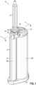
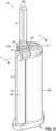
- the dispensing assembly 10 generally includes a separated-outlet cartridge 12, a single-inlet static mixer 14, and an adapter 16 that releasably couples the static mixer 14 with the cartridge 12.
- the adapter 16 advantageously enables use of a single-inlet static mixer 14 with a separated-outlet cartridge 12 for dispensing operations, whereas such mixers and cartridges are otherwise generally incompatible with one another. Moreover, the adapter 16 lockingly engages the static mixer 14, such as through a snap fit engagement, and selectively and releasably engages the cartridge 12.
- the static mixer 14 and adapter 16 may be preassembled and shipped to users for attachment to and use with existing supplies of separated-outlet cartridges, such as cartridge 12.
- separated-outlet refers to dispensing components having first and second fluid outlet/inlet members (also referred to as “ports”), each defining a respect fluid outlet/inlet passage and having a respect sealing surface for sealingly engaging a corresponding fluid inlet/outlet member of another dispensing component.
- separated-outlet cartridge 12 includes a first fluid outlet member defining a first fluid outlet passage and having a first fluid outlet sealing surface, and a separate second fluid outlet member defining a second fluid outlet passage and having a second fluid outlet sealing surface.
- single-inlet and “single-bore” refer to dispensing components having a single fluid inlet or bore defining a corresponding single fluid passage and having a single sealing surface for sealingly engaging a corresponding member of another dispensing component.
- single-inlet static mixer 14 includes a single fluid inlet defining a single fluid inlet passage and having a single fluid inlet sealing surface.
- the separated-outlet cartridge 12 includes a fluid chamber 18 that extends between a proximal end 20 and a distal end 22 of the cartridge 12.
- the fluid chamber 18 includes first and second fluid chamber portions 18a, 18b arranged adjacent to one another.
- the fluid chamber portions 18a, 18b are configured to contain first and second fluids, respectively, to be mixed together before dispensing, such as two reactive components that mix to form an adhesive material.
- first and second fluid chamber portions 18a, 18b are shown with differing sizes in the Figures, it will be understood that the fluid chamber portions 18a, 18b may be resized relative to one another in other embodiments consistent with the invention. Moreover, the fluid chamber 18 may include more or fewer fluid chamber portions in other embodiments without departing from the invention.
- the proximal end 20 of the cartridge 12 is configured to receive an actuator (not shown) such as a pneumatically or mechanically actuated piston for pushing the fluids out of the fluid chamber 18 and into the static mixer 14.
- the distal end 22 of the separated-outlet cartridge 12 includes an outlet socket 24 configured for connecting to a separated-inlet mixer (not shown).
- the outlet socket 24 includes a landing surface 26 and first and second fluid outlet members 28, 30 (also referred to as outlet "ports") extending distally from the landing surface 26 and arranged adjacent to one another.
- the first fluid outlet member 28 defines a first fluid outlet passage 32 that communicates with the first fluid chamber portion 18a, and which has a first inner sealing surface 34.
- the second fluid outlet member 30 defines a second fluid outlet passage 36 that communicates with the second fluid chamber portion 18b, and which has a second inner sealing surface 38. While the fluid outlet members 28, 30 are shown as differently sized tubular members having substantially circular cross-sectional shapes, it will be appreciated that the fluid outlet members 28, 30 may be formed with various alternative shapes and with various alternative sizing.
- the outlet socket 24 further includes first and second fingers 40, 42 extending distally from diametrically opposed sides of the landing surface 26.
- the first and second fingers 40, 42 may extend partially circumferentially about the first and second fluid outlet members 28, 30, and overhang the landing surface 26 to define respective first and second locking channels 44, 46 configured for lockingly engaging bayonet lugs 58, 60 formed on a static mixer 14.
- the adapter 16 is advantageously provided with bayonet lugs 94, 96 for releasably engaging a fluid cartridge, thereby facilitating connection of a single-inlet static mixer with a separated-outlet fluid cartridge, such as cartridge 12 and static mixer 14, for example.
- the single-inlet static mixer 14 includes a mixer housing 48 extending between a proximal end 50 having a mixer flange 52 and a distal end 54 having a dispensing tip 56.
- the mixer flange 52 includes first and second L-shaped bayonet lugs 58, 60 extending radially outward from generally opposite sides of the mixer flange 52.
- the mixer housing 48 generally houses a mixing elements (not shown) having one or more known mixing baffles of various types for rotating and combining one or more fluids together as the fluid(s) traverse the length of the mixer housing 48.
- One or more reinforcement ribs 61 may be arranged circumferentially about the mixer flange 52 and extend distally from the proximal end 50.
- the static mixer 14 includes a single fluid inlet 62 defining a single fluid inlet passage 64 and having a single inner sealing surface 66.
- the fluid inlet passage 64 opens to a central bore 68 in which the mixing element (not shown) is arranged.
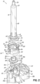
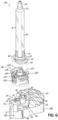
- the exemplary adapter 16 connects the single-inlet mixer 14 to the separated-outlet fluid cartridge 12, and includes a locking nut 70 and a separately formed connecting disc 72 removably received within the locking nut 70. While the adapter 16 is shown herein in use with static mixer 14 and fluid cartridge 12, each having specific structural features, it will be appreciated that the adapter 16 may be suitably modified for use with single-inlet mixers and separated-outlet cartridges of various alternative types, without departing from the invention.
- the locking nut 70 is generally annular in shape and includes a proximal base portion 74 defining a proximal opening 76 and at least one locking element for locking the adapter 16 to the static mixer 14, and shown in the form of first and second locking jaws 78, 80.
- the first and second locking jaws 78, 80 extend distally from the base portion 74 to define a distal opening 82 of the locking nut 70, and are arranged generally opposite of one another and separated by circumferential gaps 84.
- the locking jaws 78, 80 may flare radially outward from the base portion 74, and each locking jaw 78, 80 includes a circumferentially extending slot 86 and a lip 88 that overhangs the slot 86.
- the circumferential slots 86 in the locking jaws 78, 80 are sized and shaped to receive the bayonet lugs 58, 60 formed on the mixer flange 52, so that the static mixer 14 may lockingly connect to the locking nut 70 with a snap fit engagement in which the mixer bayonet lugs 58, 60 project through the circumferential slots 86.
- each of the circumferential slots 86 may be formed with one or more notches or recesses for accommodating correspondingly shaped features projecting from the mixer bayonet lugs 58, 60.
- the locking jaws 78, 80 retain the mixer flange 52 so as to substantially inhibit rotation between the mixer housing 48 and the locking nut 70.
- the circumferential gaps 84 between the locking jaws 78, 80 may be suitably sized, and the locking nut 70 may be formed of a suitably elastic and resilient material, to allow the locking jaws 78, 80 to flex radially outward when engaging the mixer flange 52.
- the lip 88 of each locking jaw 78, 80 may be tapered at a radially inner surface, thereby providing the distal opening 82 with a funnel-like shape for facilitating alignment and snap fit of the mixer flange 52 within the locking jaws 78, 80.
- the interior of the locking nut 70 may include one or more axial grooves 90 extending distally from the proximal base portion 74 for facilitating alignment of the connecting disc 72 with the locking nut 70 during assembly, as described below.
- the locking nut 70 includes four axial grooves 90 arranged at uniform circumferential spacings, but it will be understood that alternative quantities and arrangements of axial grooves 90 or other alignment features may be provided.
- the interior of the locking nut 70 may further include an internal ledge 92 that extends radially inward toward and circumferentially about the connecting disc 72. As described below, the internal ledge 92 substantially inhibits proximal movement of the connecting disc 72 relative to the locking nut 70 following assembly. As shown, the internal ledge 92 may be formed proximally of the circumferential slots 86 of the locking jaws 78, 80, and the axial grooves 90 may extend through the internal ledge 92.
- the locking nut 70 may further include first and second L-shaped bayonet lugs 94, 96 for releasably locking the locking nut 70 to the cartridge 12.
- the bayonet lugs 94, 96 extend radially outward from generally opposite sides of the proximal base portion 74, and are sized to be received within the locking channels 44, 46 formed in the outlet socket 24 of the cartridge 12 when the locking nut 70 is rotated. As described below, the locking nut 70 is rotatable relative to the cartridge 12 between locked and unlocked positions.
- the connecting disc 72 of the adapter 16 generally includes a radially extending disc flange 100, first and second fluid inlet members 102, 104 (also referred to as inlet "ports") extending proximally from a proximal side of the disc flange 100, and a single fluid outlet member 106 extending distally from a distal side of the disc flange 100.
- the fluid inlet members 102, 104 are spaced radially from one another and may be diametrically opposed about a central axis of the connecting disc 72.
- the first fluid inlet member 102 defines a first fluid inlet passage 108 and has a first outer sealing surface 110.
- the second fluid inlet member 104 defines a second fluid inlet passage 112 and has a second outer sealing surface 114.
- the fluid outlet member 106 of the connecting disc 72 includes a single outer sealing surface 116, and defines first and second fluid outlet passages 118, 120 separated by a dividing wall 122.
- the first fluid outlet passage 118 communicates with the first fluid inlet passage 108
- the second fluid outlet passage 120 communicates with the second fluid inlet passage 112.
- the first and second fluid outlet passages 118, 120 may be formed with non-circular cross-sectional shapes, such as cat-eye shape, and the first and second fluid inlet passages 108, 112 may be formed with substantially circular cross-sectional shapes.
- each of the fluid inlet and outlet members 102, 104, 106 of the connecting disc 72 may be substantially cylindrical in shape.
- the fluid inlet and outlet members 102, 104, 106 and corresponding fluid passages may be formed with various alternative shapes. Exemplary alternative configurations are described in greater detail below in connection with FIGS. 9-16 .
- the fluid outlet passages 118, 120 of the connecting disc 72 may be substantially equal in size for directing substantially equal volumes of respective first and second fluids from the first and second chamber portions 18a, 18b of the fluid cartridge 12 into the static mixer 14.
- the first and second fluid outlet passages 118, 120 may be equally sized to deliver a 1:1 volume ratio of first fluid to second fluid into the static mixer 14.
- features of the connecting disc 72, including the fluid outlet passages 118, 120 may be differently sized to deliver alternative ratios of first fluid to second fluid into the static mixer 14, such as described below in connection with FIGS. 13-16 , for example.
- the connecting disc 72 may include one or more protrusions 124 extending radially outward from an outer edge of the disc flange 100.
- Each radial protrusion 124 is sized to seat within one of the axial grooves 90 formed on the interior of the locking nut 70, for maintaining the connecting disc 72 in circumferential alignment with the locking nut 70 as the connecting disc 72 is pressed into the locking nut 70 through the proximal opening 76 during assembly.
- the radial protrusions 124 may be formed in quantity and circumferential arrangement similar to the axial grooves 90.
- relief depressions 126 may be formed at each circumferential side of each radial protrusion 124 for enabling the radial protrusions 124 to flex relative to the disc flange 100 during assembly.
- the adapter 16 may first be assembled with the single-inlet static mixer 14, which assembly may then be shipped to a user who later attaches the adapter 16 to a separated-outlet cartridge 12 for dispensing with the static mixer 14. Accordingly, and advantageously, the adapter 16 enables use of a single-inlet mixer with a separated-outlet cartridge, when combined use of such dispensing components is otherwise generally unachievable.
- the proximal flange 52 of the static mixer 14 is aligned coaxially with the distal opening 82 of the locking nut 70, and the bayonet lugs 58, 60 on the mixer flange 52 are aligned circumferentially with the circumferential slots 86 in the locking jaws 78, 80.
- the mixer flange 52 is then pressed through the distal opening 82, against the lips 88, thereby causing the first and second locking jaws 78, 80 to flex radially outward until the bayonet lugs 58, 60 snap into the circumferential slots 86, at which point the locking jaws 78, 80 may at least partially return toward their relaxed positions.
- the locking engagement of the static mixer 14 with the locking nut 70 substantially inhibits axial and rotational movement of the static mixer 14 relative to the locking nut 70.
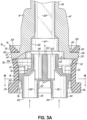
- the connecting disc 72 is aligned coaxially with the proximal opening 76 of the locking nut 70 such that the fluid outlet member 106 faces distally, and the radial protrusions 124 are aligned circumferentially with the axial grooves 90. As shown in FIGS. 3A-4 , the connecting disc 72 is pressed distally through the locking nut 70.
- the connecting disc flange 100 may be sized so as to engage the inner face of the adapter 16 with an interference fit. As shown in FIG.
- the connecting disc 72 is advanced distally until a distal side of the connecting disc flange 100 confronts the mixer flange 52 and a proximal side of the connecting disc flange 100 confronts the internal ledge 92 of the locking nut 70.
- the fluid outlet member 106 is received within the fluid inlet 62 of the static mixer 14 such that the outer sealing surface 116 of the fluid outlet member 106 sealingly engages the inner sealing surface 66 of the static mixer 14, thereby forming a liquid-tight seal.
- the fluid inlet members 102, 104 of the connecting disc 72 are accessible through the proximal opening 76 of the locking nut 70.
- the connecting disc 72 is movable distally through the locking nut 70 toward the distal opening 82 without obstruction.
- the connecting disc 72 may be passed distally through the distal opening 82 of the locking nut 70, if desired.
- the mixer-adapter assembly may be connected to the separated-outlet cartridge 12.
- the proximal end of the locking nut 70 is aligned coaxially with the cartridge outlet socket 24, and circumferentially such that the locking nut bayonet lugs 94, 96 are positioned between the first and second fingers 40, 42 of the cartridge 12.
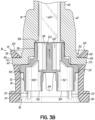
- the adapter 16 and static mixer 14 are pressed proximally toward the cartridge 12 so that the first and second fluid outlet members 28, 30 of the cartridge 12 are received through the proximal opening 76 of the locking nut 70 and sealingly engage the first and second fluid inlet members 102, 104 of the connecting disc 72.
- first and second fluid inlet members 102, 104 may be received within the respective first and second fluid outlet members 28, 30, such that the first and second outer sealing surfaces 110, 114 on the connecting disc 72 sealingly engage the first and second inner sealing surfaces 34, 38, respectively, on the cartridge 12.
- the adapter 16 is pressed proximally against the cartridge 12 until the proximal end of the locking nut 70 confronts the landing surface 26 and the fluid inlet members 102, 104 of the connecting disc 72 are fully engaged with the fluid outlet members 28, 30 of the cartridge 12, thereby positioning the adapter 16 in an unlocked position relative to the cartridge 12.
- the connecting disc 72 is non-rotatably mounted to the cartridge 12 via engagement of the fluid inlet members 102, 104 with the fluid outlet members 28, 30.
- the locking nut 70 and static mixer 14 remain rotatable relative to the connecting disc 72 and the cartridge 12.
- the locking nut 70 and static mixer 14 may be rotated together about a central axis of the connecting disc 72 into a locked position in which the locking nut bayonet lugs 94, 96 are received within the locking channels 44, 46 of the cartridge outlet socket 24, as shown in FIG. 1 .
- FIG. 3B it will be appreciated that during rotation of the adapter 16 between the unlocked and locked positions, the outer sealing surface 116 of the single fluid outlet member 106 of the connecting disc 72 moves relative to and remains sealingly engaged with the inner sealing surface 66 of the fluid inlet 62 of the static mixer 14.
- the adapter 16 and static mixer 14 may be disassembled from the cartridge 12.
- the adapter 16 and static mixer 14 are rotated together relative to the cartridge 12 back into the unlocked position in which the locking nut bayonet lugs 94, 96 are disengaged from the locking channels 44, 46 of the cartridge outlet socket 24.
- the connecting disc 72 of the adapter 16 remains non-rotatably mounted to the cartridge 12.
- the proximal side of the connecting disc flange 100 confronts the internal ledge 92 of the locking nut 70.
- the locking nut 70 and static mixer 14 may be pulled distally away from the cartridge 12, which movement causes the internal ledge 92 to contact the disc flange 100 at its proximal side and thereby simultaneously pull the connecting disc 72 away from the cartridge 12.
- removal of the locking nut 70 from the cartridge 12 advantageously also removes the connecting disc 72 from the cartridge 12, such that the cartridge 12 may be freely capped for storage or otherwise assembled with other mixing components, for example.
- the dispensing assembly 210 includes a separated-outlet cartridge 12, a single-inlet static mixer 14, and an adapter 216 that releasably couples the static mixer 14 to the cartridge 12.
- the locking nut 270 and connecting disc 272 of adapter 216 are integrally formed with frangible connections, as described in greater detail below.
- Adapter 216 is otherwise largely similar in function and construction to adapter 16 of FIGS. 1-4 , as indicated by use of similar reference numerals.
- locking nut 270 of adapter 216 includes a proximal base portion 274 defining a proximal opening 276, and first and second locking jaws 278, 280 extending distally from the base portion 274 and defining a distal opening 282.
- Each locking jaw 278, 280 includes a circumferentially extending slot 286 and a lip 288 that overhangs the slot 286.
- the circumferential slots 286 are sized and shaped to receive the bayonet lugs 58, 60 formed on the mixer flange 52, and thus may be formed with a variety of geometries, such as the exemplary geometry shown.
- a pair of support arms 290 extend distally from the base portion 274 of the locking nut 270, through the circumferential gaps 284 formed between the first and second locking jaws 278, 280.
- Each support arm 290 supports a frangible connection 291 that connects the connecting disc 272 to the locking nut 270.
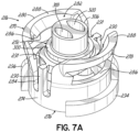
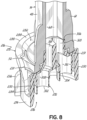
- the frangible connections 291 are shown intact in FIGS. 7A and 8 , prior to the adapter 216 being first rotated from the unlocked position into the locked position relative to the cartridge 12. As described below, upon a first rotation of the locking nut 270 into the locked position, the frangible connections 291 are broken. While FIG. 7B shows the connecting disc 272 artificially displaced from the locking nut 270 to reveal interior details of the locking nut 270, this view illustrates the general location at which the frangible connections 291 break upon the first rotation of the locking nut 270.
- the interior of the locking nut 270 further includes a pair of internal ledges 292 extending radially inward from the first and second locking jaws 278, 280, toward the connecting disc 272 (shown displaced distally).
- the internal ledges 292 may be diametrically opposed from one another, for example at positions adjacent to the circumferential gaps 284, and are positioned to confront a proximal side of the connecting disc 272 when the adapter 216 is in the unlocked position relative to the cartridge 12, as shown in FIG. 5 . While the first and second internal ledges 292 are shown as separate elements, it will be appreciated that various alternative configurations of the internal ledges 292 may be provided.
- Connecting disc 272 of adapter 216 includes a radially extending disc flange 300, first and second fluid inlet members 302, 304 extending proximally from a proximal side of the disc flange 300, and a single fluid outlet member 306 extending distally from a distal side of the disc flange 300.
- the disc flange 300 may be formed with one or more flattened or recessed sides ( see , e.g., FIGS. 9-16 ), or an otherwise non-circular shape, for accommodating mold support structure (not shown) positioned between the locking nut 270 and the connecting disc 272 during formation of the adapter 216.
- proximal flange 52 of the static mixer 14 is aligned coaxially with the distal opening 282 of the locking nut 270, and the bayonet lugs 58, 60 on the mixer flange 52 are aligned circumferentially with the circumferential slots 286 in the locking jaws 278, 280.
- the mixer flange 52 is then pressed proximally through the distal opening 282 until the mixer bayonet lugs 58, 60 snap into the circumferential slots 286, in a manner similar to that described above in connection with adapter 16.
- the connecting disc 272 is already connected to the locking nut 270 via frangible connections 291
- the fluid outlet member 306 of the connecting disc 272 is received within and sealingly engages the fluid inlet 62 of the static mixer 14, as shown in FIG. 8 .
- the mixer housing 48 is non-rotatably mounted to the locking nut 270.
- the assembled static mixer 14 and adapter 216 are then aligned with and coupled to the separated-outlet cartridge 12 in a manner similar to that described above for adapter 216.
- the connecting disc 272 is non-rotatably mounted to the cartridge 12.
- the locking nut 270 rotates about the connecting disc 272, thereby breaking the frangible connections 291 so that the locking nut 270 and connecting disc 272 are no longer integral.
- the adapter 216 is rotated from the locked position back to the unlocked position with respect to the cartridge 12.
- the internal ledges 292 of the locking nut 270 are positioned proximally of and confront a proximal side of the disc flange 300.
- the internal ledges 292 contact and pull the connecting disc 272 away from the cartridge 12, such that the cartridge 12 may be freely capped for storage or otherwise assembled with other mixing components, for example.
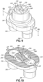
- FIGS. 9-16 alternative exemplary embodiments of connecting discs are shown. These connecting discs are largely similar to connecting disc 272 of FIGS. 5-8 , as indicated by use of similar reference numerals. However, it will be appreciated that the features of these alternative connecting discs may also be applied to connecting disc 72 of adapter 16 to generate further alternative embodiments. The following descriptions emphasize the unique features of the exemplary connecting discs of FIGS 9-16 , which relate primarily to the internal geometries of the corresponding fluid outlet members.
- exemplary connecting disc 330 includes a fluid layering element 332 arranged within the fluid outlet member 334.
- the fluid layering element 332 functions to provide an initial layering of first and second fluids directed through the fluid outlet member 334 as the fluids pass into the static mixer 14, thereby enhancing the mixing effect provided by the static mixer 14.
- the exemplary fluid layering element 332 is shown in the form of a plurality of axially extending planar walls formed integrally with the fluid outlet member 334, and defining a plurality of fluid layer passages through which fluid is directed. It will be appreciated that fluid layering elements having various alternative configurations may also be provided.
- the exemplary fluid layering element 332 shown includes a first outer wall 336, a second outer wall 338, and an intermediate wall 340 extending between the first and second outer walls 336, 338.
- a first fluid layer passage 342 is defined between the first outer wall 336 and an inner face of the fluid outlet member 334.
- a second fluid layer passage 344 is defined between the first outer wall 336 and the intermediate wall 340.
- a third fluid layer passage 346 is defined between the intermediate wall 340 and the second outer wall 338.
- a fourth fluid layer passage 348 is defined between the second outer wall 338 and an inner face of the fluid outlet member 334, at a radial position substantially opposite that of the first fluid layer passage 342.
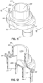
- the first and fourth fluid layer passages 342, 348 may each have a semi-circular cross-sectional shape, while the second and third fluid layer passages 344, 346 may each have a generally rectangular cross-sectional shape. As shown best in FIG. 10 , the first fluid inlet passage 308 communicates with the first and third fluid layer passages 342, 346, and the second fluid inlet passage 312 communicates with the second and fourth fluid layer passages 344, 348.
- exemplary connecting disc 350 includes a fluid outlet member 352 defining a single fluid outlet passage 354 that communicates with the first fluid inlet passage 308 and also with the second fluid inlet passage 312.
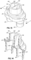
- exemplary connecting disc 360 includes a fluid outlet member 362 having first and second fluid outlet passages 364, 366 defined by a dividing wall 368 extending axially through the fluid outlet member 362 from the disc flange 300.
- the dividing wall 368 may be positioned centrally within the fluid outlet member 362 so that the first and second fluid outlet passages 364, 366 are substantially equal in cross-sectional area so as to deliver a 1:1 volume ratio of first fluid to second fluid into the static mixer 14.
- the dividing wall 368 may be alternatively positioned at various radial distances from a central axis of the fluid outlet member 362, so as to define first and second fluid outlet passages of differing cross-sectional areas for delivering alternative ratios of first fluid to second fluid into the static mixer 14.
- exemplary connecting disc 370 includes a fluid outlet member 372 having a dividing wall 374 that is radially offset from a central axis of the fluid outlet member 372, so as to define first and second fluid outlet passages 376, 378 of differing cross-sectional areas. More specifically, the dividing wall 374 may be positioned radially so that the cross-sectional area of the first fluid outlet passage 376 is approximately twice that of the second fluid outlet passage 378, for example, for delivering a 2:1 volume ratio of first fluid to second fluid into the static mixer 14.
- a second fluid inlet member 380 of the connecting disc 370 may be sized smaller than the first fluid inlet member 302 for defining a corresponding second fluid inlet passage 382 having a smaller cross-sectional area than the first fluid inlet passage 308.
Landscapes
- Engineering & Computer Science (AREA)
- Mechanical Engineering (AREA)
- General Engineering & Computer Science (AREA)
- Accessories For Mixers (AREA)
- Coating Apparatus (AREA)
- Infusion, Injection, And Reservoir Apparatuses (AREA)
- Quick-Acting Or Multi-Walled Pipe Joints (AREA)
Applications Claiming Priority (2)
| Application Number | Priority Date | Filing Date | Title |
|---|---|---|---|
| US14/995,252 US10281074B2 (en) | 2016-01-14 | 2016-01-14 | Adapters for connecting a separated-outlet fluid cartridge to a single-inlet mixer, and related methods |
| PCT/US2017/012416 WO2017123458A1 (en) | 2016-01-14 | 2017-01-06 | Adapters for connecting a separated-outlet fluid cartridge to a single-inlet mixer, and related methods |
Publications (2)
| Publication Number | Publication Date |
|---|---|
| EP3402609A1 EP3402609A1 (en) | 2018-11-21 |
| EP3402609B1 true EP3402609B1 (en) | 2023-03-08 |
Family
ID=57882170
Family Applications (1)
| Application Number | Title | Priority Date | Filing Date |
|---|---|---|---|
| EP17701383.6A Active EP3402609B1 (en) | 2016-01-14 | 2017-01-06 | Adapters for connecting a separated-outlet fluid cartridge to a single-inlet mixer, and related methods |
Country Status (6)
| Country | Link |
|---|---|
| US (2) | US10281074B2 (enExample) |
| EP (1) | EP3402609B1 (enExample) |
| JP (1) | JP6914941B2 (enExample) |
| KR (1) | KR102535435B1 (enExample) |
| CN (1) | CN108463291B (enExample) |
| WO (1) | WO2017123458A1 (enExample) |
Families Citing this family (15)
| Publication number | Priority date | Publication date | Assignee | Title |
|---|---|---|---|---|
| US10369589B2 (en) * | 2017-05-12 | 2019-08-06 | Alan Dale | Nozzle adapter |
| US11813581B2 (en) * | 2017-07-14 | 2023-11-14 | 3M Innovative Properties Company | Method and adapter for conveying plural liquid streams |
| JP6643375B2 (ja) * | 2018-02-13 | 2020-02-12 | 櫻護謨株式会社 | ポリウレア噴射装置 |
| US20210069419A1 (en) * | 2018-03-29 | 2021-03-11 | Nordson Corporation | Cap and cartridge assembly |
| DE102018119838A1 (de) * | 2018-08-15 | 2020-02-20 | Atlas Copco Ias Gmbh | Vorrichtung zum Auftragen eines mindestens zweikomponentigen viskosen Materials auf Werkstücke |
| US20200070189A1 (en) * | 2018-08-30 | 2020-03-05 | Nordson Corporation | Adapter mixer attachment |
| EP3914397A1 (en) * | 2019-01-24 | 2021-12-01 | Nordson Corporation | Multi-material dispensing system having a quick-connect fluid dispenser that releasably couples to a pump housing |
| EP3771495A1 (en) * | 2019-07-29 | 2021-02-03 | Sulzer Mixpac AG | Discharge arrangement, component, accessory, method of connecting an accessory to a component, and system |
| US11872535B2 (en) * | 2020-01-03 | 2024-01-16 | Huanghua Promisee Dental Co., Ltd. | Connecting chuck of material cylinder for mixer and mixer |
| US11896993B2 (en) * | 2020-07-24 | 2024-02-13 | Albion Engineering Company | Common head having an offset partition for use with multi-component dispensing tools and a tubular liner arranged for locating within the common head |
| US20230003324A1 (en) * | 2021-07-01 | 2023-01-05 | Wilmarc Holdings, Llc | Genderless Aseptic Connector |
| CN119233866A (zh) * | 2022-05-19 | 2024-12-31 | 迈德米斯瑞士股份公司 | 分配系统和分配出口 |
| WO2024062453A1 (en) * | 2022-09-23 | 2024-03-28 | 3M Innovative Properties Company | Fluid nozzle and fluid system |
| CN121001812A (zh) * | 2023-03-29 | 2025-11-21 | 汉高股份有限及两合公司 | 用于双组分化合物料筒的混合器适配器以及配备该适配器的混合器-料筒组件 |
| WO2026067967A1 (en) * | 2024-09-25 | 2026-04-02 | Medmix Switzerland Ag | Adapter for a dispensing system and dispensing system |
Family Cites Families (35)
| Publication number | Priority date | Publication date | Assignee | Title |
|---|---|---|---|---|
| DE3018438A1 (de) * | 1980-05-14 | 1981-11-19 | Upat Gmbh & Co, 7830 Emmendingen | Vorrichtung zum aktivieren und dosieren haertbarer massen |
| DK315483A (da) * | 1982-07-17 | 1984-01-18 | Lingner & Fischer Gmbh | Dispenser til vaeskeformige klaebemidler |
| CH681146A5 (enExample) * | 1990-07-20 | 1993-01-29 | Wilhelm A Keller | |
| DE59207545D1 (de) | 1992-07-17 | 1997-01-02 | Wilhelm A Keller | Austragkartusche |
| US5333760A (en) | 1992-12-28 | 1994-08-02 | Coltene/Whaledent, Inc. | Dispensing and mixing apparatus |
| US5413253A (en) | 1993-12-06 | 1995-05-09 | Coltene/Whaledent, Inc. | Static mixer |
| US5609271A (en) | 1995-01-25 | 1997-03-11 | Wilhelm A. Keller | Mixer and multiple component dispensing device assembly and method for the aligned connection of the mixer to the multiple component dispensing device |
| ES2164750T3 (es) * | 1995-03-07 | 2002-03-01 | Wilhelm A Keller | Dispositivo de fijacion por bayoneta para sujetar un accesorio a un cartucho de componentes multiples o dispositivo distribuidor. |
| US5918772A (en) | 1995-03-13 | 1999-07-06 | Wilhelm A. Keller | Bayonet fastening device for the attachment of an accessory to a multiple component cartridge or dispensing device |
| US6769574B1 (en) | 1995-03-13 | 2004-08-03 | Mixpac Systems Ag | Dispensing assembly having coded attachment of an accessory to a multiple component cartridge or dispensing device using differently sized inlets and outlets |
| DE69605642T2 (de) | 1996-02-21 | 2000-05-11 | Wilhelm A. Keller | Mittel zur richtigen Befestigung einer Mehrkomponentenkartusche auf einem Austraggerät |
| DE69716887T2 (de) | 1997-06-18 | 2003-03-20 | Wilhelm A. Keller | Mischer |
| JP2000126569A (ja) * | 1998-09-18 | 2000-05-09 | Sulzer Chemtech Ag | 複数の流動性成分の混合分配を行う装置 |
| DE29902666U1 (de) | 1999-02-15 | 2000-06-29 | Ernst Mühlbauer KG, 22547 Hamburg | Vorrichtung zum Ausgeben gemischter Mehrkomponentenmassen, insbesondere für zahnärztliche Zwecke |
| US6345776B1 (en) | 1999-12-23 | 2002-02-12 | Fomo Products Inc. | Two-component dispensing gun |
| DE10233051A1 (de) * | 2002-07-19 | 2004-02-05 | Coltène/Whaledent GmbH + Co. KG | Abgabesystem für fluide Substanzen |
| US20080029542A1 (en) * | 2004-07-08 | 2008-02-07 | Mixpac Systems Ag | Dispensing Assembly for Two Components , Including a Syringe or Dispensing Cartidge and a Mixer |
| GB0417593D0 (en) | 2004-08-06 | 2004-09-08 | Cox Ltd | Dispensing gun |
| GB0504990D0 (en) | 2005-03-10 | 2005-04-20 | Cox Ltd | Dispensing appliance and cartridge therefor |
| DE202006004738U1 (de) | 2006-03-24 | 2006-06-01 | Euro-Lock-Vertriebs-Gmbh | Vorrichtung für das Mischen zweier Fluide |
| AU2008229561B2 (en) | 2007-03-19 | 2013-05-16 | Sulzer Mixpac Ag | Dispensing assembly having removably attachable accessories |
| JP5172514B2 (ja) | 2008-07-15 | 2013-03-27 | 株式会社ジーシー | ミキシングチップ |
| CH699398A1 (de) | 2008-08-22 | 2010-02-26 | Medmix Systems Ag | Anschlussstück für Austragvorrichtung. |
| CA2686581C (en) * | 2009-02-11 | 2017-06-27 | Sulzer Mixpac Ag | Intermediate piece for the connection of a storage container to a static mixer |
| TWI524932B (zh) * | 2009-03-11 | 2016-03-11 | 素路彩米克斯派克股份有限公司 | 用於排出填料的設備 |
| EP2485852B1 (de) | 2009-10-06 | 2013-10-30 | Medmix Systems AG | Austraganordnung mit einer verbindungsvorrichtung zwischen einer mehrkomponenten-kartusche und einem zubehörteil |
| KR100954836B1 (ko) * | 2009-12-18 | 2010-04-28 | (주)세일글로발 | 인상재 카트리지의 믹싱팁 결합구조 |
| US8365958B2 (en) * | 2010-02-12 | 2013-02-05 | Phillip Phung-I Ho | Device for mixing and discharging plural materials |
| EP2407249A1 (de) | 2010-07-16 | 2012-01-18 | Sulzer Mixpac AG | Zwischenstück zur Verbindung einer Kartusche mit einem statischen Mischer |
| BR112013010171B1 (pt) | 2010-10-26 | 2020-12-22 | 3lmed GmbH | Combinação que consiste em um cartucho duplo e um misturador para o uso do mesmo |
| CA2775346C (en) | 2011-07-22 | 2019-03-05 | Sulzer Mixpac Ag | Static mixer |
| CA2789725C (en) | 2011-11-29 | 2019-08-06 | Sulzer Mixpac Ag | Mixing element for a static mixer |
| US8960501B2 (en) * | 2012-10-23 | 2015-02-24 | Nordson Corporation | Dispensing assembly and method for dispensing a mixed fluid |
| US9138772B2 (en) | 2012-10-31 | 2015-09-22 | Nordson Corporation | Dispensing assembly and method using snap engagement of a mixer and a cartridge |
| US9289797B2 (en) | 2012-11-06 | 2016-03-22 | Nordson Corporation | Dispensing assembly and method for assembling a dispenser and dispensing a fluid |
-
2016
- 2016-01-14 US US14/995,252 patent/US10281074B2/en active Active
-
2017
- 2017-01-06 JP JP2018535417A patent/JP6914941B2/ja not_active Expired - Fee Related
- 2017-01-06 WO PCT/US2017/012416 patent/WO2017123458A1/en not_active Ceased
- 2017-01-06 CN CN201780006530.9A patent/CN108463291B/zh not_active Expired - Fee Related
- 2017-01-06 KR KR1020187022613A patent/KR102535435B1/ko active Active
- 2017-01-06 EP EP17701383.6A patent/EP3402609B1/en active Active
-
2019
- 2019-03-22 US US16/361,211 patent/US11168821B2/en not_active Expired - Fee Related
Also Published As
| Publication number | Publication date |
|---|---|
| WO2017123458A1 (en) | 2017-07-20 |
| US11168821B2 (en) | 2021-11-09 |
| CN108463291A (zh) | 2018-08-28 |
| US20190219208A1 (en) | 2019-07-18 |
| US20170205009A1 (en) | 2017-07-20 |
| KR102535435B1 (ko) | 2023-05-24 |
| JP2019508226A (ja) | 2019-03-28 |
| KR20180103952A (ko) | 2018-09-19 |
| US10281074B2 (en) | 2019-05-07 |
| EP3402609A1 (en) | 2018-11-21 |
| CN108463291B (zh) | 2020-12-29 |
| JP6914941B2 (ja) | 2021-08-04 |
Similar Documents
| Publication | Publication Date | Title |
|---|---|---|
| EP3402609B1 (en) | Adapters for connecting a separated-outlet fluid cartridge to a single-inlet mixer, and related methods | |
| JP7033087B2 (ja) | 単一入口ミキサに分離出口流体カートリッジを接続するためのアダプタ、及び、その関連方法 | |
| US6065645A (en) | Double-barreled syringe with detachable locking mixing tip | |
| EP0733022B1 (en) | Sealing attachment for connecting a dual chambered cartridge and a static mixer | |
| US6698622B2 (en) | Double-barreled syringe with detachable locking mixing tip | |
| EP2563524B1 (en) | Apparatus for mixing and dispensing multiple flowable components | |
| US20080029542A1 (en) | Dispensing Assembly for Two Components , Including a Syringe or Dispensing Cartidge and a Mixer | |
| EP2139786B1 (en) | Dispensing assembly having removably attachable accessories | |
| US8371744B2 (en) | Mixer and system for mixing and dispensing a material | |
| JP7015245B2 (ja) | 第1の流体及び第2の流体を小出しする並置型カートリッジ組立体 | |
| EP3283389B1 (en) | Fluid cartridge system and method of using a fluid cartridge system | |
| US20210069419A1 (en) | Cap and cartridge assembly | |
| EP3197607B1 (en) | Head plate device, storage container device, cartridge arrangement, dispensing apparatus, and their usage | |
| EP3797076B1 (en) | Cap and cartridge assembly | |
| EP3368200B1 (en) | Mixer | |
| GB2625278A (en) | Mixer, cartridge and assembly |
Legal Events
| Date | Code | Title | Description |
|---|---|---|---|
| STAA | Information on the status of an ep patent application or granted ep patent |
Free format text: STATUS: UNKNOWN |
|
| STAA | Information on the status of an ep patent application or granted ep patent |
Free format text: STATUS: THE INTERNATIONAL PUBLICATION HAS BEEN MADE |
|
| PUAI | Public reference made under article 153(3) epc to a published international application that has entered the european phase |
Free format text: ORIGINAL CODE: 0009012 |
|
| STAA | Information on the status of an ep patent application or granted ep patent |
Free format text: STATUS: REQUEST FOR EXAMINATION WAS MADE |
|
| 17P | Request for examination filed |
Effective date: 20180807 |
|
| AK | Designated contracting states |
Kind code of ref document: A1 Designated state(s): AL AT BE BG CH CY CZ DE DK EE ES FI FR GB GR HR HU IE IS IT LI LT LU LV MC MK MT NL NO PL PT RO RS SE SI SK SM TR |
|
| AX | Request for extension of the european patent |
Extension state: BA ME |
|
| DAV | Request for validation of the european patent (deleted) | ||
| DAX | Request for extension of the european patent (deleted) | ||
| STAA | Information on the status of an ep patent application or granted ep patent |
Free format text: STATUS: EXAMINATION IS IN PROGRESS |
|
| 17Q | First examination report despatched |
Effective date: 20201102 |
|
| GRAP | Despatch of communication of intention to grant a patent |
Free format text: ORIGINAL CODE: EPIDOSNIGR1 |
|
| STAA | Information on the status of an ep patent application or granted ep patent |
Free format text: STATUS: GRANT OF PATENT IS INTENDED |
|
| INTG | Intention to grant announced |
Effective date: 20220914 |
|
| GRAS | Grant fee paid |
Free format text: ORIGINAL CODE: EPIDOSNIGR3 |
|
| GRAA | (expected) grant |
Free format text: ORIGINAL CODE: 0009210 |
|
| STAA | Information on the status of an ep patent application or granted ep patent |
Free format text: STATUS: THE PATENT HAS BEEN GRANTED |
|
| AK | Designated contracting states |
Kind code of ref document: B1 Designated state(s): AL AT BE BG CH CY CZ DE DK EE ES FI FR GB GR HR HU IE IS IT LI LT LU LV MC MK MT NL NO PL PT RO RS SE SI SK SM TR |
|
| REG | Reference to a national code |
Ref country code: GB Ref legal event code: FG4D |
|
| REG | Reference to a national code |
Ref country code: CH Ref legal event code: EP Ref country code: AT Ref legal event code: REF Ref document number: 1552220 Country of ref document: AT Kind code of ref document: T Effective date: 20230315 |
|
| REG | Reference to a national code |
Ref country code: DE Ref legal event code: R096 Ref document number: 602017066588 Country of ref document: DE |
|
| REG | Reference to a national code |
Ref country code: IE Ref legal event code: FG4D |
|
| REG | Reference to a national code |
Ref country code: LT Ref legal event code: MG9D |
|
| REG | Reference to a national code |
Ref country code: NL Ref legal event code: MP Effective date: 20230308 |
|
| PG25 | Lapsed in a contracting state [announced via postgrant information from national office to epo] |
Ref country code: RS Free format text: LAPSE BECAUSE OF FAILURE TO SUBMIT A TRANSLATION OF THE DESCRIPTION OR TO PAY THE FEE WITHIN THE PRESCRIBED TIME-LIMIT Effective date: 20230308 Ref country code: NO Free format text: LAPSE BECAUSE OF FAILURE TO SUBMIT A TRANSLATION OF THE DESCRIPTION OR TO PAY THE FEE WITHIN THE PRESCRIBED TIME-LIMIT Effective date: 20230608 Ref country code: LV Free format text: LAPSE BECAUSE OF FAILURE TO SUBMIT A TRANSLATION OF THE DESCRIPTION OR TO PAY THE FEE WITHIN THE PRESCRIBED TIME-LIMIT Effective date: 20230308 Ref country code: LT Free format text: LAPSE BECAUSE OF FAILURE TO SUBMIT A TRANSLATION OF THE DESCRIPTION OR TO PAY THE FEE WITHIN THE PRESCRIBED TIME-LIMIT Effective date: 20230308 Ref country code: HR Free format text: LAPSE BECAUSE OF FAILURE TO SUBMIT A TRANSLATION OF THE DESCRIPTION OR TO PAY THE FEE WITHIN THE PRESCRIBED TIME-LIMIT Effective date: 20230308 Ref country code: ES Free format text: LAPSE BECAUSE OF FAILURE TO SUBMIT A TRANSLATION OF THE DESCRIPTION OR TO PAY THE FEE WITHIN THE PRESCRIBED TIME-LIMIT Effective date: 20230308 |
|
| REG | Reference to a national code |
Ref country code: AT Ref legal event code: MK05 Ref document number: 1552220 Country of ref document: AT Kind code of ref document: T Effective date: 20230308 |
|
| PG25 | Lapsed in a contracting state [announced via postgrant information from national office to epo] |
Ref country code: SE Free format text: LAPSE BECAUSE OF FAILURE TO SUBMIT A TRANSLATION OF THE DESCRIPTION OR TO PAY THE FEE WITHIN THE PRESCRIBED TIME-LIMIT Effective date: 20230308 Ref country code: NL Free format text: LAPSE BECAUSE OF FAILURE TO SUBMIT A TRANSLATION OF THE DESCRIPTION OR TO PAY THE FEE WITHIN THE PRESCRIBED TIME-LIMIT Effective date: 20230308 Ref country code: GR Free format text: LAPSE BECAUSE OF FAILURE TO SUBMIT A TRANSLATION OF THE DESCRIPTION OR TO PAY THE FEE WITHIN THE PRESCRIBED TIME-LIMIT Effective date: 20230609 Ref country code: FI Free format text: LAPSE BECAUSE OF FAILURE TO SUBMIT A TRANSLATION OF THE DESCRIPTION OR TO PAY THE FEE WITHIN THE PRESCRIBED TIME-LIMIT Effective date: 20230308 |
|
| PG25 | Lapsed in a contracting state [announced via postgrant information from national office to epo] |
Ref country code: SM Free format text: LAPSE BECAUSE OF FAILURE TO SUBMIT A TRANSLATION OF THE DESCRIPTION OR TO PAY THE FEE WITHIN THE PRESCRIBED TIME-LIMIT Effective date: 20230308 Ref country code: RO Free format text: LAPSE BECAUSE OF FAILURE TO SUBMIT A TRANSLATION OF THE DESCRIPTION OR TO PAY THE FEE WITHIN THE PRESCRIBED TIME-LIMIT Effective date: 20230308 Ref country code: PT Free format text: LAPSE BECAUSE OF FAILURE TO SUBMIT A TRANSLATION OF THE DESCRIPTION OR TO PAY THE FEE WITHIN THE PRESCRIBED TIME-LIMIT Effective date: 20230710 Ref country code: EE Free format text: LAPSE BECAUSE OF FAILURE TO SUBMIT A TRANSLATION OF THE DESCRIPTION OR TO PAY THE FEE WITHIN THE PRESCRIBED TIME-LIMIT Effective date: 20230308 Ref country code: CZ Free format text: LAPSE BECAUSE OF FAILURE TO SUBMIT A TRANSLATION OF THE DESCRIPTION OR TO PAY THE FEE WITHIN THE PRESCRIBED TIME-LIMIT Effective date: 20230308 Ref country code: AT Free format text: LAPSE BECAUSE OF FAILURE TO SUBMIT A TRANSLATION OF THE DESCRIPTION OR TO PAY THE FEE WITHIN THE PRESCRIBED TIME-LIMIT Effective date: 20230308 |
|
| PG25 | Lapsed in a contracting state [announced via postgrant information from national office to epo] |
Ref country code: SK Free format text: LAPSE BECAUSE OF FAILURE TO SUBMIT A TRANSLATION OF THE DESCRIPTION OR TO PAY THE FEE WITHIN THE PRESCRIBED TIME-LIMIT Effective date: 20230308 Ref country code: PL Free format text: LAPSE BECAUSE OF FAILURE TO SUBMIT A TRANSLATION OF THE DESCRIPTION OR TO PAY THE FEE WITHIN THE PRESCRIBED TIME-LIMIT Effective date: 20230308 Ref country code: IS Free format text: LAPSE BECAUSE OF FAILURE TO SUBMIT A TRANSLATION OF THE DESCRIPTION OR TO PAY THE FEE WITHIN THE PRESCRIBED TIME-LIMIT Effective date: 20230708 |
|
| REG | Reference to a national code |
Ref country code: DE Ref legal event code: R097 Ref document number: 602017066588 Country of ref document: DE |
|
| PLBE | No opposition filed within time limit |
Free format text: ORIGINAL CODE: 0009261 |
|
| STAA | Information on the status of an ep patent application or granted ep patent |
Free format text: STATUS: NO OPPOSITION FILED WITHIN TIME LIMIT |
|
| PG25 | Lapsed in a contracting state [announced via postgrant information from national office to epo] |
Ref country code: SI Free format text: LAPSE BECAUSE OF FAILURE TO SUBMIT A TRANSLATION OF THE DESCRIPTION OR TO PAY THE FEE WITHIN THE PRESCRIBED TIME-LIMIT Effective date: 20230308 Ref country code: DK Free format text: LAPSE BECAUSE OF FAILURE TO SUBMIT A TRANSLATION OF THE DESCRIPTION OR TO PAY THE FEE WITHIN THE PRESCRIBED TIME-LIMIT Effective date: 20230308 |
|
| 26N | No opposition filed |
Effective date: 20231211 |
|
| PG25 | Lapsed in a contracting state [announced via postgrant information from national office to epo] |
Ref country code: IT Free format text: LAPSE BECAUSE OF FAILURE TO SUBMIT A TRANSLATION OF THE DESCRIPTION OR TO PAY THE FEE WITHIN THE PRESCRIBED TIME-LIMIT Effective date: 20230308 |
|
| REG | Reference to a national code |
Ref country code: DE Ref legal event code: R119 Ref document number: 602017066588 Country of ref document: DE |
|
| PG25 | Lapsed in a contracting state [announced via postgrant information from national office to epo] |
Ref country code: MC Free format text: LAPSE BECAUSE OF FAILURE TO SUBMIT A TRANSLATION OF THE DESCRIPTION OR TO PAY THE FEE WITHIN THE PRESCRIBED TIME-LIMIT Effective date: 20230308 |
|
| PG25 | Lapsed in a contracting state [announced via postgrant information from national office to epo] |
Ref country code: MC Free format text: LAPSE BECAUSE OF FAILURE TO SUBMIT A TRANSLATION OF THE DESCRIPTION OR TO PAY THE FEE WITHIN THE PRESCRIBED TIME-LIMIT Effective date: 20230308 |
|
| REG | Reference to a national code |
Ref country code: CH Ref legal event code: PL |
|
| PG25 | Lapsed in a contracting state [announced via postgrant information from national office to epo] |
Ref country code: LU Free format text: LAPSE BECAUSE OF NON-PAYMENT OF DUE FEES Effective date: 20240106 |
|
| GBPC | Gb: european patent ceased through non-payment of renewal fee |
Effective date: 20240106 |
|
| PG25 | Lapsed in a contracting state [announced via postgrant information from national office to epo] |
Ref country code: LU Free format text: LAPSE BECAUSE OF NON-PAYMENT OF DUE FEES Effective date: 20240106 |
|
| PG25 | Lapsed in a contracting state [announced via postgrant information from national office to epo] |
Ref country code: DE Free format text: LAPSE BECAUSE OF NON-PAYMENT OF DUE FEES Effective date: 20240801 |
|
| PG25 | Lapsed in a contracting state [announced via postgrant information from national office to epo] |
Ref country code: GB Free format text: LAPSE BECAUSE OF NON-PAYMENT OF DUE FEES Effective date: 20240106 |
|
| PG25 | Lapsed in a contracting state [announced via postgrant information from national office to epo] |
Ref country code: BE Free format text: LAPSE BECAUSE OF NON-PAYMENT OF DUE FEES Effective date: 20240131 |
|
| PG25 | Lapsed in a contracting state [announced via postgrant information from national office to epo] |
Ref country code: FR Free format text: LAPSE BECAUSE OF NON-PAYMENT OF DUE FEES Effective date: 20240131 |
|
| PG25 | Lapsed in a contracting state [announced via postgrant information from national office to epo] |
Ref country code: CH Free format text: LAPSE BECAUSE OF NON-PAYMENT OF DUE FEES Effective date: 20240131 |
|
| PG25 | Lapsed in a contracting state [announced via postgrant information from national office to epo] |
Ref country code: GB Free format text: LAPSE BECAUSE OF NON-PAYMENT OF DUE FEES Effective date: 20240106 Ref country code: FR Free format text: LAPSE BECAUSE OF NON-PAYMENT OF DUE FEES Effective date: 20240131 Ref country code: DE Free format text: LAPSE BECAUSE OF NON-PAYMENT OF DUE FEES Effective date: 20240801 Ref country code: CH Free format text: LAPSE BECAUSE OF NON-PAYMENT OF DUE FEES Effective date: 20240131 Ref country code: BE Free format text: LAPSE BECAUSE OF NON-PAYMENT OF DUE FEES Effective date: 20240131 |
|
| REG | Reference to a national code |
Ref country code: BE Ref legal event code: MM Effective date: 20240131 |
|
| PG25 | Lapsed in a contracting state [announced via postgrant information from national office to epo] |
Ref country code: BG Free format text: LAPSE BECAUSE OF FAILURE TO SUBMIT A TRANSLATION OF THE DESCRIPTION OR TO PAY THE FEE WITHIN THE PRESCRIBED TIME-LIMIT Effective date: 20230308 |
|
| PG25 | Lapsed in a contracting state [announced via postgrant information from national office to epo] |
Ref country code: BG Free format text: LAPSE BECAUSE OF FAILURE TO SUBMIT A TRANSLATION OF THE DESCRIPTION OR TO PAY THE FEE WITHIN THE PRESCRIBED TIME-LIMIT Effective date: 20230308 |
|
| PG25 | Lapsed in a contracting state [announced via postgrant information from national office to epo] |
Ref country code: IE Free format text: LAPSE BECAUSE OF NON-PAYMENT OF DUE FEES Effective date: 20240106 |
|
| PG25 | Lapsed in a contracting state [announced via postgrant information from national office to epo] |
Ref country code: IE Free format text: LAPSE BECAUSE OF NON-PAYMENT OF DUE FEES Effective date: 20240106 |
|
| PG25 | Lapsed in a contracting state [announced via postgrant information from national office to epo] |
Ref country code: CY Free format text: LAPSE BECAUSE OF FAILURE TO SUBMIT A TRANSLATION OF THE DESCRIPTION OR TO PAY THE FEE WITHIN THE PRESCRIBED TIME-LIMIT; INVALID AB INITIO Effective date: 20170106 |
|
| PG25 | Lapsed in a contracting state [announced via postgrant information from national office to epo] |
Ref country code: HU Free format text: LAPSE BECAUSE OF FAILURE TO SUBMIT A TRANSLATION OF THE DESCRIPTION OR TO PAY THE FEE WITHIN THE PRESCRIBED TIME-LIMIT; INVALID AB INITIO Effective date: 20170106 |
|
| PG25 | Lapsed in a contracting state [announced via postgrant information from national office to epo] |
Ref country code: TR Free format text: LAPSE BECAUSE OF FAILURE TO SUBMIT A TRANSLATION OF THE DESCRIPTION OR TO PAY THE FEE WITHIN THE PRESCRIBED TIME-LIMIT Effective date: 20230308 |