EP3401563A1 - Abstandskontrolle-taumelscheibenvorrichtung und einwelliges zweiganggetriebesystem mit darauf aufgebrachter rutschkupplung - Google Patents
Abstandskontrolle-taumelscheibenvorrichtung und einwelliges zweiganggetriebesystem mit darauf aufgebrachter rutschkupplung Download PDFInfo
- Publication number
- EP3401563A1 EP3401563A1 EP17180455.2A EP17180455A EP3401563A1 EP 3401563 A1 EP3401563 A1 EP 3401563A1 EP 17180455 A EP17180455 A EP 17180455A EP 3401563 A1 EP3401563 A1 EP 3401563A1
- Authority
- EP
- European Patent Office
- Prior art keywords
- swash plate
- clearance
- ring gear
- worm
- clearance swash
- Prior art date
- Legal status (The legal status is an assumption and is not a legal conclusion. Google has not performed a legal analysis and makes no representation as to the accuracy of the status listed.)
- Granted
Links
- 230000009471 action Effects 0.000 claims abstract description 22
- 230000009467 reduction Effects 0.000 claims description 29
- 230000003247 decreasing effect Effects 0.000 claims description 10
- 230000002265 prevention Effects 0.000 claims description 4
- 229910000831 Steel Inorganic materials 0.000 claims description 3
- 239000010959 steel Substances 0.000 claims description 3
- 230000005540 biological transmission Effects 0.000 abstract description 10
- 239000003638 chemical reducing agent Substances 0.000 abstract description 7
- 238000005516 engineering process Methods 0.000 description 8
- 238000000034 method Methods 0.000 description 6
- 230000006870 function Effects 0.000 description 4
- 230000035807 sensation Effects 0.000 description 4
- 230000000694 effects Effects 0.000 description 2
- 239000000446 fuel Substances 0.000 description 2
- 238000009434 installation Methods 0.000 description 2
- 238000012986 modification Methods 0.000 description 2
- 230000004048 modification Effects 0.000 description 2
- 230000008878 coupling Effects 0.000 description 1
- 238000010168 coupling process Methods 0.000 description 1
- 238000005859 coupling reaction Methods 0.000 description 1
- 238000003754 machining Methods 0.000 description 1
- 230000010363 phase shift Effects 0.000 description 1
- 230000001629 suppression Effects 0.000 description 1
Images


Classifications
-
- F—MECHANICAL ENGINEERING; LIGHTING; HEATING; WEAPONS; BLASTING
- F16—ENGINEERING ELEMENTS AND UNITS; GENERAL MEASURES FOR PRODUCING AND MAINTAINING EFFECTIVE FUNCTIONING OF MACHINES OR INSTALLATIONS; THERMAL INSULATION IN GENERAL
- F16H—GEARING
- F16H37/00—Combinations of mechanical gearings, not provided for in groups F16H1/00 - F16H35/00
- F16H37/02—Combinations of mechanical gearings, not provided for in groups F16H1/00 - F16H35/00 comprising essentially only toothed or friction gearings
- F16H37/06—Combinations of mechanical gearings, not provided for in groups F16H1/00 - F16H35/00 comprising essentially only toothed or friction gearings with a plurality of driving or driven shafts; with arrangements for dividing torque between two or more intermediate shafts
- F16H37/08—Combinations of mechanical gearings, not provided for in groups F16H1/00 - F16H35/00 comprising essentially only toothed or friction gearings with a plurality of driving or driven shafts; with arrangements for dividing torque between two or more intermediate shafts with differential gearing
- F16H37/0806—Combinations of mechanical gearings, not provided for in groups F16H1/00 - F16H35/00 comprising essentially only toothed or friction gearings with a plurality of driving or driven shafts; with arrangements for dividing torque between two or more intermediate shafts with differential gearing with a plurality of driving or driven shafts
- F16H37/0813—Combinations of mechanical gearings, not provided for in groups F16H1/00 - F16H35/00 comprising essentially only toothed or friction gearings with a plurality of driving or driven shafts; with arrangements for dividing torque between two or more intermediate shafts with differential gearing with a plurality of driving or driven shafts with only one input shaft
- F16H37/082—Combinations of mechanical gearings, not provided for in groups F16H1/00 - F16H35/00 comprising essentially only toothed or friction gearings with a plurality of driving or driven shafts; with arrangements for dividing torque between two or more intermediate shafts with differential gearing with a plurality of driving or driven shafts with only one input shaft and additional planetary reduction gears
-
- F—MECHANICAL ENGINEERING; LIGHTING; HEATING; WEAPONS; BLASTING
- F16—ENGINEERING ELEMENTS AND UNITS; GENERAL MEASURES FOR PRODUCING AND MAINTAINING EFFECTIVE FUNCTIONING OF MACHINES OR INSTALLATIONS; THERMAL INSULATION IN GENERAL
- F16D—COUPLINGS FOR TRANSMITTING ROTATION; CLUTCHES; BRAKES
- F16D19/00—Clutches with mechanically-actuated clutching members not otherwise provided for
-
- B—PERFORMING OPERATIONS; TRANSPORTING
- B60—VEHICLES IN GENERAL
- B60K—ARRANGEMENT OR MOUNTING OF PROPULSION UNITS OR OF TRANSMISSIONS IN VEHICLES; ARRANGEMENT OR MOUNTING OF PLURAL DIVERSE PRIME-MOVERS IN VEHICLES; AUXILIARY DRIVES FOR VEHICLES; INSTRUMENTATION OR DASHBOARDS FOR VEHICLES; ARRANGEMENTS IN CONNECTION WITH COOLING, AIR INTAKE, GAS EXHAUST OR FUEL SUPPLY OF PROPULSION UNITS IN VEHICLES
- B60K17/00—Arrangement or mounting of transmissions in vehicles
- B60K17/04—Arrangement or mounting of transmissions in vehicles characterised by arrangement, location, or kind of gearing
- B60K17/06—Arrangement or mounting of transmissions in vehicles characterised by arrangement, location, or kind of gearing of change-speed gearing
- B60K17/08—Arrangement or mounting of transmissions in vehicles characterised by arrangement, location, or kind of gearing of change-speed gearing of mechanical type
-
- B—PERFORMING OPERATIONS; TRANSPORTING
- B60—VEHICLES IN GENERAL
- B60K—ARRANGEMENT OR MOUNTING OF PROPULSION UNITS OR OF TRANSMISSIONS IN VEHICLES; ARRANGEMENT OR MOUNTING OF PLURAL DIVERSE PRIME-MOVERS IN VEHICLES; AUXILIARY DRIVES FOR VEHICLES; INSTRUMENTATION OR DASHBOARDS FOR VEHICLES; ARRANGEMENTS IN CONNECTION WITH COOLING, AIR INTAKE, GAS EXHAUST OR FUEL SUPPLY OF PROPULSION UNITS IN VEHICLES
- B60K17/00—Arrangement or mounting of transmissions in vehicles
- B60K17/04—Arrangement or mounting of transmissions in vehicles characterised by arrangement, location, or kind of gearing
- B60K17/16—Arrangement or mounting of transmissions in vehicles characterised by arrangement, location, or kind of gearing of differential gearing
-
- F—MECHANICAL ENGINEERING; LIGHTING; HEATING; WEAPONS; BLASTING
- F16—ENGINEERING ELEMENTS AND UNITS; GENERAL MEASURES FOR PRODUCING AND MAINTAINING EFFECTIVE FUNCTIONING OF MACHINES OR INSTALLATIONS; THERMAL INSULATION IN GENERAL
- F16D—COUPLINGS FOR TRANSMITTING ROTATION; CLUTCHES; BRAKES
- F16D11/00—Clutches in which the members have interengaging parts
- F16D11/14—Clutches in which the members have interengaging parts with clutching members movable only axially
-
- F—MECHANICAL ENGINEERING; LIGHTING; HEATING; WEAPONS; BLASTING
- F16—ENGINEERING ELEMENTS AND UNITS; GENERAL MEASURES FOR PRODUCING AND MAINTAINING EFFECTIVE FUNCTIONING OF MACHINES OR INSTALLATIONS; THERMAL INSULATION IN GENERAL
- F16D—COUPLINGS FOR TRANSMITTING ROTATION; CLUTCHES; BRAKES
- F16D13/00—Friction clutches
- F16D13/22—Friction clutches with axially-movable clutching members
- F16D13/38—Friction clutches with axially-movable clutching members with flat clutching surfaces, e.g. discs
- F16D13/52—Clutches with multiple lamellae ; Clutches in which three or more axially moveable members are fixed alternately to the shafts to be coupled and are pressed from one side towards an axially-located member
-
- F—MECHANICAL ENGINEERING; LIGHTING; HEATING; WEAPONS; BLASTING
- F16—ENGINEERING ELEMENTS AND UNITS; GENERAL MEASURES FOR PRODUCING AND MAINTAINING EFFECTIVE FUNCTIONING OF MACHINES OR INSTALLATIONS; THERMAL INSULATION IN GENERAL
- F16D—COUPLINGS FOR TRANSMITTING ROTATION; CLUTCHES; BRAKES
- F16D23/00—Details of mechanically-actuated clutches not specific for one distinct type
- F16D23/02—Arrangements for synchronisation, also for power-operated clutches
- F16D23/025—Synchro rings
-
- F—MECHANICAL ENGINEERING; LIGHTING; HEATING; WEAPONS; BLASTING
- F16—ENGINEERING ELEMENTS AND UNITS; GENERAL MEASURES FOR PRODUCING AND MAINTAINING EFFECTIVE FUNCTIONING OF MACHINES OR INSTALLATIONS; THERMAL INSULATION IN GENERAL
- F16D—COUPLINGS FOR TRANSMITTING ROTATION; CLUTCHES; BRAKES
- F16D23/00—Details of mechanically-actuated clutches not specific for one distinct type
- F16D23/02—Arrangements for synchronisation, also for power-operated clutches
- F16D23/04—Arrangements for synchronisation, also for power-operated clutches with an additional friction clutch
-
- F—MECHANICAL ENGINEERING; LIGHTING; HEATING; WEAPONS; BLASTING
- F16—ENGINEERING ELEMENTS AND UNITS; GENERAL MEASURES FOR PRODUCING AND MAINTAINING EFFECTIVE FUNCTIONING OF MACHINES OR INSTALLATIONS; THERMAL INSULATION IN GENERAL
- F16D—COUPLINGS FOR TRANSMITTING ROTATION; CLUTCHES; BRAKES
- F16D23/00—Details of mechanically-actuated clutches not specific for one distinct type
- F16D23/12—Mechanical clutch-actuating mechanisms arranged outside the clutch as such
-
- F—MECHANICAL ENGINEERING; LIGHTING; HEATING; WEAPONS; BLASTING
- F16—ENGINEERING ELEMENTS AND UNITS; GENERAL MEASURES FOR PRODUCING AND MAINTAINING EFFECTIVE FUNCTIONING OF MACHINES OR INSTALLATIONS; THERMAL INSULATION IN GENERAL
- F16D—COUPLINGS FOR TRANSMITTING ROTATION; CLUTCHES; BRAKES
- F16D28/00—Electrically-actuated clutches
-
- F—MECHANICAL ENGINEERING; LIGHTING; HEATING; WEAPONS; BLASTING
- F16—ENGINEERING ELEMENTS AND UNITS; GENERAL MEASURES FOR PRODUCING AND MAINTAINING EFFECTIVE FUNCTIONING OF MACHINES OR INSTALLATIONS; THERMAL INSULATION IN GENERAL
- F16H—GEARING
- F16H19/00—Gearings comprising essentially only toothed gears or friction members and not capable of conveying indefinitely-continuing rotary motion
- F16H19/001—Gearings comprising essentially only toothed gears or friction members and not capable of conveying indefinitely-continuing rotary motion for conveying reciprocating or limited rotary motion
-
- F—MECHANICAL ENGINEERING; LIGHTING; HEATING; WEAPONS; BLASTING
- F16—ENGINEERING ELEMENTS AND UNITS; GENERAL MEASURES FOR PRODUCING AND MAINTAINING EFFECTIVE FUNCTIONING OF MACHINES OR INSTALLATIONS; THERMAL INSULATION IN GENERAL
- F16H—GEARING
- F16H3/00—Toothed gearings for conveying rotary motion with variable gear ratio or for reversing rotary motion
- F16H3/44—Toothed gearings for conveying rotary motion with variable gear ratio or for reversing rotary motion using gears having orbital motion
- F16H3/46—Gearings having only two central gears, connected by orbital gears
- F16H3/48—Gearings having only two central gears, connected by orbital gears with single orbital gears or pairs of rigidly-connected orbital gears
- F16H3/52—Gearings having only two central gears, connected by orbital gears with single orbital gears or pairs of rigidly-connected orbital gears comprising orbital spur gears
- F16H3/54—Gearings having only two central gears, connected by orbital gears with single orbital gears or pairs of rigidly-connected orbital gears comprising orbital spur gears one of the central gears being internally toothed and the other externally toothed
-
- F—MECHANICAL ENGINEERING; LIGHTING; HEATING; WEAPONS; BLASTING
- F16—ENGINEERING ELEMENTS AND UNITS; GENERAL MEASURES FOR PRODUCING AND MAINTAINING EFFECTIVE FUNCTIONING OF MACHINES OR INSTALLATIONS; THERMAL INSULATION IN GENERAL
- F16H—GEARING
- F16H57/00—General details of gearing
- F16H57/08—General details of gearing of gearings with members having orbital motion
- F16H57/10—Braking arrangements
-
- F—MECHANICAL ENGINEERING; LIGHTING; HEATING; WEAPONS; BLASTING
- F16—ENGINEERING ELEMENTS AND UNITS; GENERAL MEASURES FOR PRODUCING AND MAINTAINING EFFECTIVE FUNCTIONING OF MACHINES OR INSTALLATIONS; THERMAL INSULATION IN GENERAL
- F16H—GEARING
- F16H63/00—Control outputs from the control unit to change-speed- or reversing-gearings for conveying rotary motion or to other devices than the final output mechanism
- F16H63/02—Final output mechanisms therefor; Actuating means for the final output mechanisms
- F16H63/30—Constructional features of the final output mechanisms
- F16H63/3003—Band brake actuating mechanisms
-
- F—MECHANICAL ENGINEERING; LIGHTING; HEATING; WEAPONS; BLASTING
- F16—ENGINEERING ELEMENTS AND UNITS; GENERAL MEASURES FOR PRODUCING AND MAINTAINING EFFECTIVE FUNCTIONING OF MACHINES OR INSTALLATIONS; THERMAL INSULATION IN GENERAL
- F16D—COUPLINGS FOR TRANSMITTING ROTATION; CLUTCHES; BRAKES
- F16D23/00—Details of mechanically-actuated clutches not specific for one distinct type
- F16D23/02—Arrangements for synchronisation, also for power-operated clutches
- F16D23/04—Arrangements for synchronisation, also for power-operated clutches with an additional friction clutch
- F16D23/06—Arrangements for synchronisation, also for power-operated clutches with an additional friction clutch and a blocking mechanism preventing the engagement of the main clutch prior to synchronisation
- F16D2023/0625—Details of members being coupled, e.g. gears
-
- F—MECHANICAL ENGINEERING; LIGHTING; HEATING; WEAPONS; BLASTING
- F16—ENGINEERING ELEMENTS AND UNITS; GENERAL MEASURES FOR PRODUCING AND MAINTAINING EFFECTIVE FUNCTIONING OF MACHINES OR INSTALLATIONS; THERMAL INSULATION IN GENERAL
- F16D—COUPLINGS FOR TRANSMITTING ROTATION; CLUTCHES; BRAKES
- F16D23/00—Details of mechanically-actuated clutches not specific for one distinct type
- F16D23/12—Mechanical clutch-actuating mechanisms arranged outside the clutch as such
- F16D2023/123—Clutch actuation by cams, ramps or ball-screw mechanisms
-
- F—MECHANICAL ENGINEERING; LIGHTING; HEATING; WEAPONS; BLASTING
- F16—ENGINEERING ELEMENTS AND UNITS; GENERAL MEASURES FOR PRODUCING AND MAINTAINING EFFECTIVE FUNCTIONING OF MACHINES OR INSTALLATIONS; THERMAL INSULATION IN GENERAL
- F16D—COUPLINGS FOR TRANSMITTING ROTATION; CLUTCHES; BRAKES
- F16D2125/00—Components of actuators
- F16D2125/18—Mechanical mechanisms
- F16D2125/20—Mechanical mechanisms converting rotation to linear movement or vice versa
- F16D2125/34—Mechanical mechanisms converting rotation to linear movement or vice versa acting in the direction of the axis of rotation
- F16D2125/42—Rack-and-worm gears
-
- F—MECHANICAL ENGINEERING; LIGHTING; HEATING; WEAPONS; BLASTING
- F16—ENGINEERING ELEMENTS AND UNITS; GENERAL MEASURES FOR PRODUCING AND MAINTAINING EFFECTIVE FUNCTIONING OF MACHINES OR INSTALLATIONS; THERMAL INSULATION IN GENERAL
- F16D—COUPLINGS FOR TRANSMITTING ROTATION; CLUTCHES; BRAKES
- F16D49/00—Brakes with a braking member co-operating with the periphery of a drum, wheel-rim, or the like
- F16D49/08—Brakes with a braking member co-operating with the periphery of a drum, wheel-rim, or the like shaped as an encircling band extending over approximately 360 degrees
- F16D49/10—Brakes with a braking member co-operating with the periphery of a drum, wheel-rim, or the like shaped as an encircling band extending over approximately 360 degrees mechanically actuated
-
- F—MECHANICAL ENGINEERING; LIGHTING; HEATING; WEAPONS; BLASTING
- F16—ENGINEERING ELEMENTS AND UNITS; GENERAL MEASURES FOR PRODUCING AND MAINTAINING EFFECTIVE FUNCTIONING OF MACHINES OR INSTALLATIONS; THERMAL INSULATION IN GENERAL
- F16H—GEARING
- F16H2200/00—Transmissions for multiple ratios
- F16H2200/003—Transmissions for multiple ratios characterised by the number of forward speeds
- F16H2200/0034—Transmissions for multiple ratios characterised by the number of forward speeds the gear ratios comprising two forward speeds
-
- F—MECHANICAL ENGINEERING; LIGHTING; HEATING; WEAPONS; BLASTING
- F16—ENGINEERING ELEMENTS AND UNITS; GENERAL MEASURES FOR PRODUCING AND MAINTAINING EFFECTIVE FUNCTIONING OF MACHINES OR INSTALLATIONS; THERMAL INSULATION IN GENERAL
- F16H—GEARING
- F16H2200/00—Transmissions for multiple ratios
- F16H2200/20—Transmissions using gears with orbital motion
- F16H2200/2002—Transmissions using gears with orbital motion characterised by the number of sets of orbital gears
- F16H2200/2005—Transmissions using gears with orbital motion characterised by the number of sets of orbital gears with one sets of orbital gears
-
- F—MECHANICAL ENGINEERING; LIGHTING; HEATING; WEAPONS; BLASTING
- F16—ENGINEERING ELEMENTS AND UNITS; GENERAL MEASURES FOR PRODUCING AND MAINTAINING EFFECTIVE FUNCTIONING OF MACHINES OR INSTALLATIONS; THERMAL INSULATION IN GENERAL
- F16H—GEARING
- F16H2200/00—Transmissions for multiple ratios
- F16H2200/20—Transmissions using gears with orbital motion
- F16H2200/203—Transmissions using gears with orbital motion characterised by the engaging friction means not of the freewheel type, e.g. friction clutches or brakes
- F16H2200/2035—Transmissions using gears with orbital motion characterised by the engaging friction means not of the freewheel type, e.g. friction clutches or brakes with two engaging means
Definitions
- the present invention relates generally to a clearance control swash plate device for a transmission or reducer and a single-shaft two-speed drive system, including the clearance control swash plate device, with a friction clutch applied thereto, and more particularly to a field in which a technology for implementing reduction via a clearance control swash plate device and planetary gears is applied to vehicles and similar drive systems.
- a transmission is installed between a clutch and a drive shaft, and functions to selectively increase and decrease the rotation force of an engine depending on the driving state of a vehicle and to transfer the rotation force to drive wheels.
- the synchronizer of a manual transmission includes a main shaft gear configured to be rotated around a main shaft, a hub coupled to the main shaft, a gear cone installed between the main shaft gear and the hub, a sleeve coupled to the hub in a spline manner and configured to move in an axial direction, and a synchronizer ring configured to be engaged with the gear cone during a gear shift and to function as a clutch by means of frictional force.
- Synchronization methods can be classified into key-type methods and pin-type methods.
- Key-type methods are applied to small-sized vehicles, and provide a smooth gear shift sensation during a gear shift.
- Pin-type methods enable strong synchronization force to be obtained, and thus can be applied to medium- and full-sized vehicles.
- a pin-type synchronizer is problematic in that a gear shift sensation cannot be smooth because a sleeve should be moved over a ring-shaped synchronizer pin having a height difference and in that a space cannot be efficiently utilized because the pin-type synchronizer occupies a large space for a friction capacity.
- FIG. 9 is a perspective view showing a conventional synchronizer which improves the gear shift sensation of a pin-type manual transmission.
- the conventional synchronizer includes: a transmitter 5 configured to include one or more fastening openings 3; and first and second synchronizer rings 100 and 110 connected to each other.
- the two synchronizer rings 100 and 110 are connected to each other through the fastening openings 3.
- most parts of the synchronizer rings need to be finished through machining, and a spring, thrust parts 4, two transmission tooth portions 6, and two coupling tooth portions 7 need to be installed in addition to the transmitter 5 and the pair of synchronizer rings 100 and 110. Accordingly, this synchronizer is problematic in that the number of parts and the cost are increased.
- a conventional vehicle drive unit includes: a housing configured to surround a motor; a reducer disposed on a separate shaft; and a differential configured to receive the driving force of the reducer.
- the motor including a rotor and a stator is disposed inside the housing, one end of a first shaft is coupled to the rotor so as to operate in conjunction with the rotor, the other end of the first shaft is coupled to the differential so as to operate in conjunction with the differential on the same axial line, and the differential is connected to the reducer, including a second shaft having a different phase shift.
- the vehicle drive unit has the structure in which the reducer needs to be separately disposed outside the housing, and thus the vehicle drive unit is disadvantageous in that the space in which the reducer is installed can be limited and overall volume and weight can be increased. Furthermore, the volume and weight of the conventional drive unit are increased due to the structural characteristics of a connection structure configured to connect multiple shafts, and thus the conventional drive unit is problematic in that fuel efficiency is degraded.
- FIG. 10 is a sectional view showing a reduction device which mitigates a conventional problem related to volume, weight, and cost.
- the conventional drive unit includes: a housing 10; a motor unit configured to include a stator 30 fastened to the inner circumference of the housing 10 and adapted such that a coil is wound around the stator 30, and a rotor 20 disposed inside the stator 30 and adapted to be rotated when power is applied to the coil; a first planetary gear set configured to include a first sun gear 70A adapted to be rotated in conjunction with the rotor 20 via a linkage means, a plurality of first planetary gears 60A engaged with the first sun gear 70A and adapted to be rotated in conjunction with the first sun gear 70A, a ring gear 50 adapted to include an internal gear 52 engaged with the first planetary gears 60A, and a first carrier 80A adapted to operate in conjunction with the first planetary gears 60A; and a differential gear unit 90 connected to the first carrier 80A so as to operate in conjunction with the first carrier 80A.
- a planetary gear set, a motor, and a differential are densely disposed along the same shaft inside a single housing. Accordingly, a limitation related to an installation space can be reduced by decreasing the volume of the device, the number of parts and weight can be reduced, and noise and vibration can be reduced because power transfer and reduction are performed on the single same axial line.
- the drive unit device of this patent is problematic in that only a reduction ratio suitable for the inherent characteristic of the planetary gear set is passively obtained.
- FIG. 11 is a perspective view showing a device which mitigates the gear shift problem of a conventional reduction device.
- the synchronizer ring of a conventional synchronizer includes: a spline portion 10 configured to include a plurality of splines 12 formed on the outer circumference thereof in a circumferential direction thereof; and a cylindrical body portion 20 configured such that a plurality of friction protrusions 22 adapted to enable clutch action is formed in a circumferential direction thereof at identical intervals.
- reduction can be performed on a single axial line.
- the device is problematic in that the transfer of power is stopped during a gear shift.
- the present invention is intended to obtain two improved reduction ratios through the application of the features of planetary gears and the planetary gear principle via a band brake and disks by using a clearance control swash plate device and a planetary gear set along the same axial line without changing a shaft.
- an embodiment of the present invention provides a device that can implement two speeds by using a clearance control swash plate device, a planetary gear set, a reduction set, a pivot gear set, and a disk set using plate disks.
- Another embodiment of the present invention provides a device that can implement two speeds by using a clearance control swash plate device, a planetary gear set, a reduction set, a pivot gear set, and a disk set using cone disks.
- a clearance control swash plate device including:
- the first clearance swash plate may further include rotation prevention protrusions each formed in a shape, including one or more convex portions, on the outer circumference of the first clearance swash plate so as to prevent the first clearance swash plate from being rotated when being pushed by the rotation of the second clearance swash plate.
- the first or second clearance swash plate may be made of stamped steel.
- the clearance control swash plate device may further include a worm drive motor configured to rotate the worm.
- a single-shaft two-speed drive system with a friction clutch applied thereto configured to include the clearance control swash plate device and to perform power transfer and reduction on a single power transfer shaft, the system including:
- the plane or clutch disks may be cone clutches.
- the plane or clutch disks may be plate disks.
- the single-shaft two-speed drive system may further include a pivot gear set including a pivot gear configured such that one side thereof is rotatably connected to the first pivot connection part of the band brake and the other side thereof is rotatably connected to a second pivot connection part installed on a portion of the outer circumference of the second clearance swash plate.
- the second pivot connection part may be rotated by the rotation of the second clearance swash plate, and the pivot gear set may be rotated by the rotation of the second pivot connection part, so that the first pivot connection part is rotated and the radius of the band brake is selectively increased and decreased depending on whether the second clearance swash plate is rotated forward or backward.
- a clearance control swash plate device and a single-shaft two-speed drive system including the clearance control swash plate device, with a friction clutch applied thereto will be described below.
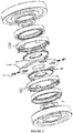
- FIG. 1 is a perspective view showing a clearance control swash plate device and a single-shaft two-speed drive system with a friction clutch applied thereto according to an embodiment of the present invention.
- the single-shaft two-speed drive system with a friction clutch applied thereto may enable power transfer and reduction to be performed on a single power transfer shaft 700, and a band brake 303 may be disposed on a ring gear drum 302.
- a ring gear 305 may be formed on the inner circumference of the ring gear drum 302, and a disk housing 304 may be formed on one side of the ring gear drum 302 to have a diameter larger than that of the ring gear drum 302.
- the disk housing 304 may have a diameter larger than that of the ring gear drum 302, and may extend from one end of the ring gear drum 302.
- Grooves configured to couple a plurality of clutch disks 403 together may be formed in the inner circumference of the disk housing 304.
- the disk housing 304 may be configured such that a plurality of plane disks 402 and the plurality of clutch disks 403 are alternately disposed inside the disk housing 304.
- the clearance control swash plate device may include: an action plate 102; a first thrust bearing 103; a first clearance swash plate 104 configured such that first swash surfaces 109 are formed on one surface thereof; a second clearance swash plate 105 configured to include a worm gear 112 formed on one side thereof, and configured such that second swash surfaces 111 are formed on one surface thereof; a second thrust bearing 106; a thrust washer 107; a worm 108; and a worm drive motor 113.
- the action plate 102 may be disposed on one surface of a disk set 401 composed of the pluralities of plane disks 402 and clutch disks 403 inside the disk housing 304.
- the clearance control swash plate device may be configured such that the action plate 102, the first thrust bearing 103, the first and second clearance swash plates 104 and 105, the second thrust bearing 106, and the thrust washer 107 are disposed in parallel on the power transfer shaft.
- a pivot gear set 601 may include a pivot gear 602, a first pivot connection part 603, and a second pivot connection part 604.
- the first pivot connection part 603 may be formed on one side of the band brake 303, and the second pivot connection part 604 may be formed on a portion of the outer circumference of the second clearance swash plate 105.
- the first and second pivot connection parts 603 and 604 may be formed in the shapes of bolts, cylinders, or the like, and may be coupled to the pivot gear 602 so as to operate in conjunction with the pivot gear 602.
- a part of the pivot gear 602 may be rotatably fastened, and the pivot gear 602 may be connected to the first and second pivot connection parts 603 and 604 so that the pivot gear 602 can increase the radius of the band brake 303 in such a manner as to be rotated when the second clearance swash plate 105 is rotated via the worm 108 and pushes the first clearance swash plate 104 toward the disk set 401.
- the pivot gear 602 can decrease the radius of the band brake 303 when the second clearance swash plate 105 returns to a state before the rotation. Since the method or principle by which the band brake 303 and the pivot gear 601 operate in conjunction with each other corresponds to a well-known technology, a detailed description thereof is omitted.
- FIG. 2 is a perspective view schematically showing the structures of the clearance control swash plate device and the single-shaft two-speed drive system with a friction clutch applied thereto according to the embodiment of the present invention.
- a reduction set 301 may include the ring gear drum 302, the band brake 303, the disk housing 304, and the ring gear 305.
- the ring gear 305 may be formed along the inner circumference of the ring gear drum 302, and the rotation of the ring gear drum 302 may be suppressed by the band brake 303.
- the first pivot connection part 603 may be formed on a portion of the outer circumference of the band brake 303.
- the first pivot connection part 603 may be connected to the pivot gear 602, and may adjust the radius of the band brake 303. Since the band brake 303 corresponds to a well-known technology, a detailed description thereof is omitted.
- the disk housing 304 may be formed at one end of the ring gear drum 302, and grooves configured to be engaged with a plurality of teeth formed on the outer circumferences of the clutch disks 403 are formed in the inner circumference of the disk housing 304.
- a planetary gear set 201 may include a sun gear 202, planetary gears 203, and a carrier 204.
- the sun gear 202 may receive power, and may transfer the power to a differential 501 via the carrier 204.
- the sun gear 202 may rotate the planetary gears 203 engaged therewith, and the ring gear 305, formed along the inner circumference of the ring gear drum 302 the rotation of which has been suppressed by the band brake 303 having a decreased radius, may be engaged with the planetary gears 203.
- the planetary gears 203 engaged with the ring gear 305 the rotation of which has been suppressed, may revolve along the teeth of the ring gear 305, and may transfer power to the carrier 204, thereby obtaining a single reduction ratio.
- the carrier 204 may be rotated at a reduction ratio based on the planetary gear principle through the engagement of the sun gear 202, the ring gear 305, and the planetary gears 203.
- the disk set 401 may include the pluralities of plane disks 402 and clutch disks 403, and the pluralities of plane disks 402 and clutch disks 403 may be formed in the shapes of plate disks or cone disks.
- a plurality of teeth may be formed on the inner circumference of each of the plane disks 402, and a plurality of teeth may be formed on the outer circumference of each of the clutch disks 403.
- the disk set 401 may be configured such that the pluralities of plane disks 402 and clutch disks 403 are alternately disposed.
- the teeth formed on the inner circumferences of the plane disks 402 may be engaged with a plurality of grooves formed in a portion of the outer circumference of the carrier 204, may be moved along the grooves, and may prevent the plane disks 402 from being rotated.
- the teeth formed on the outer circumferences of the clutch disks 403 may be engaged with a plurality of grooves formed in the inner circumference of the disk housing 304, may be moved along the grooves, and may prevent the clutch disks 403 from being rotated. Since the plane disks 402 and the clutch disks 403 correspond to well-known technologies, detailed descriptions thereof are omitted.
- the worm gear motor 113 may rotate the second clearance swash plate 105.
- the worm gear 112 may be formed on a portion of the outer circumference of the second clearance swash plate 105, and may be engaged with the worm 108 configured to be rotated via the worm gear motor 113. Since the worm 108 and the worm gear 112 correspond to well-known technologies, detailed descriptions thereof are omitted.
- the plurality of second swash surfaces 111 configured to protrude from one surface of the second clearance swash plate 105 and inclined in one circumferential direction of the second clearance swash plate 105 may be formed on the second clearance swash plate 105.
- the second pivot connection part 604 may be formed on a portion of the outer circumference of the second clearance swash plate 105.
- the second pivot connection part 604 may be rotatably connected to one side of the pivot gear 602, and the pivot gear 602 may be rotated by the rotation of the second clearance swash plate 105.
- the plurality of first swash surfaces 109 configured to protrude from one surface of the first clearance swash plate 104 and inclined in the other circumferential direction of the first clearance swash plate 104 opposite to the one direction in which the second swash surfaces 111 of the second clearance swash plate 105 are inclined may be formed on the first clearance swash plate 104.
- Rotation prevention protrusions 110 may be formed on the outer circumference of the first clearance swash plate 104 so as to prevent the first clearance swash plate 104 from being rotated when being pushed by the rotation of the second clearance swash plate 105.
- the first clearance swash plate 104 may transfer power, generated when the first clearance swash plate 104 is pushed via the second clearance swash plate 105, to the first thrust bearing 103 and the action plate 102. Accordingly, the action plate 102 may come into tight contact with the disk set 401 due to the received power, thereby bringing the plane disks 402 and clutch disks 403 of the disk set 401 into tight contact with the carrier 204.
- differential 501 corresponds to a well-known technology, a detailed description thereof is omitted.
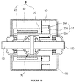
- FIG. 3 is a partially cutaway view showing the clearance control swash plate device and the single-shaft two-speed drive system with a friction clutch applied thereto according to the embodiment of the present invention.
- the second clearance swash plate 105 may be selectively rotated forward and backward via the worm 108 rotated by the worm gear motor 113 and the worm gear 112 engaged with the worm 108. Furthermore, the rotation of the second clearance swash plate 105 may stop when being sufficiently spaced apart from the first clearance swash plate 104.
- the second clearance swash plate 105 rotated by the worm gear 112 may selectively rotate the pivot gear 602 forward and backward via the second pivot connection part 604 formed on a portion of the outer circumference thereof, thereby selectively increasing and decreasing the radius of the band brake 303.
- the ring gear 305 formed along the inner circumference of the ring gear drum 302 may be released from the suppression of the band brake 303 and may be desirably rotated. Furthermore, the worm 108 may be rotated forward by the forward rotation of the worm drive motor 113. Accordingly, the second clearance swash plate 105 may be rotated forward via the worm gear 112 engaged with the worm 108, and the first clearance swash plate 104, coming into tight contact with the second swash surfaces 111 of the second clearance swash plate 105, may be pushed by the forward rotation of the second clearance swash plate 105.
- the first thrust bearing 103, coming into tight contact with the first clearance swash plate 104, and the action plate 102 may be pushed, and the disk set 401, i.e., the plane disks 402 and the clutch disks 403, may be pushed toward the carrier 204.
- the plane disks 402 and clutch disks 403 of the disk set 401 may suppress the rotation of one another when coming into tight contact with one another.
- the plane disks 402 and clutch disks 403 of the disk set 401 coming into tight contact with one another may couple the ring gear drum 302, the disk housing 304, and the carrier 204 together, and may rotate the ring gear drum 302, the disk housing 304, and the carrier 204.
- the rotation force of the sun gear 202 may be transferred to the differential 501 via the ring gear drum 302 and the carrier 204 coupled together.
- the number of revolutions of the carrier 204 may be identical to the number of revolutions of the sun gear 202.
- the worm 108 may be rotated backward by the backward rotation of the worm drive motor 113.
- the second clearance swash plate 105 may be rotated backward via the worm gear 112 engaged with the worm 108, and the tight contact state of the first clearance swash plate 104, in which the first clearance swash plate 104 has come into tight contact with the second swash surfaces 111 of the second clearance swash plate 105, may be loosened by the backward rotation of the second clearance swash plate 105, thereby loosing the tight contact state of the disk set 401 in which the disk set 401 has been pushed toward the carrier 204 by the first clearance swash plate 104.
- the carrier 204 may be separated from the ring gear drum 302.
- the sun gear 202 having received power may be engaged with the planetary gears 203, and may rotate the planetary gears 203.
- the planetary gears 203 may revolve along the teeth of the ring gear 305, and the carrier 204 coupled to the planetary gears 203 may receive reduced rotation force.
- the plane disks 402 and clutch disks 403 of the disk set 401 may be spaced apart from one another, and the plane disks 402 engaged with the grooves of the carrier 204 may be rotated along with the carrier 204.
- the carrier 204 may transfer the reduced rotation force to the differential 501.
- the second clearance swash plate 105 may be rotated backward via the worm gear 112 engaged with the worm 108, and the tight contact state of the first clearance swash plate 104, in which the first clearance swash plate 104 has come into tight contact with the second swash surfaces 111 of the second clearance swash plate 105, may be loosened by the backward rotation of the second clearance swash plate 105, thereby loosing the tight contact state of the disk set 401, in which the disk set 401 has been pushed toward the carrier 204 via the first clearance swash plate 104, and separating the carrier 204 from the ring gear drum 302.
- the number of revolutions of the carrier 204 may be generally reduced at a ratio of 3:1 to 4:1 with respect to the number of revolutions of the sun gear 202.
- Number of revolutions N C of carrier Number of teeth Z S of sun gear Number of teeth Z S of sun gear + Number of teeth Z R of ring gear ⁇ Number of revolutions N S of sun gear
- Equation 4 for example, when 30 and 60 are substituted for the number of teeth Z S of the sun gear 202 and the number of teeth Z R of the ring gear 305, respectively, the number of revolutions N C of the carrier 204 becomes 1/3 of the number of revolutions N S of the sun gear 202.
- an appropriate reduction ratio may be formed.
- the number of revolutions N C of the carrier 204 is reduced at a ratio of 3:1 to 4:1 with respect to the number of revolutions N S of the sun gear 202.
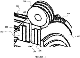
- FIG. 4 is a partially cutaway view showing the clearance control swash plate device according to the embodiment of the present invention in the state in which the second clearance swash plate 105 has been rotated.
- the second clearance swash plate 105 may be rotated via the worm gear 112 formed on a portion of the outer circumference of the second clearance swash plate 105, and may push the first clearance swash plate 104 due to the rotation thereof. Accordingly, the first and second clearance swash plates 104 and 105 may be spaced apart from each other. Furthermore, the first pushed clearance swash plate 104 may bring the first thrust bearing 103, the action plate 102, and the disk set 401 into tight contact with one another.
- the action plate 102 may transfer rotation force, generated when the action plate 102 comes into tight contact with the first thrust bearing 103 and the disk set 401, and rotation force, generated when the carrier 204 and the ring gear drum 302 are coupled together and rotated, to the first thrust bearing 103. Furthermore, the first thrust bearing 103 may prevent the rotation force from being transferred to the first clearance swash plate 104 by absorbing the rotation force. The second thrust bearing 106 may prevent rotation force, generated when the second clearance swash plate 105 is rotated by the worm 108, from being transferred to the thrust washer 107 by absorbing the rotation force. The thrust washer 107 may sustain repulsive force generated when the first clearance swash plate 104 is pushed by the rotation of the second clearance swash plate 105.
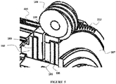
- FIG. 5 is a partially cutaway view showing the clearance control swash plate device according to the embodiment of the present invention in the state in which the first and second clearance swash plates 104 and 105 have come into tight contact with each other.
- the second clearance swash plate 105 may come into tight contact with the first clearance swash plate 104 before the worm 108 is rotated backward.
- the pluralities of plane disks 402 and clutch disks 403 of the disk set 401 may be spaced apart from one another, and the plurality of plane disks 402 may be coupled to the carrier 204 and rotated.
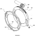
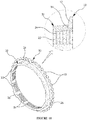
- FIG. 6 is a perspective view showing the first and second clearance swash plates 104 and 105 and the worm 108 according to the embodiment of the present invention.
- the worm gear 112 may be formed on a portion of the outer circumference of the second clearance swash plate 105, and may be engaged with the worm 108.
- the plurality of second swash surfaces 111 configured to protrude from one surface of the second clearance swash plate 105 and inclined in one circumferential direction of the second clearance swash plate 105 may be formed on the second clearance swash plate 105, and the second clearance swash plate 105 may be made of stamped steel.
- the first swash surfaces 109 configured to protrude from one surface of the first clearance swash plate 104 facing the second clearance swash plate 105 and inclined in the other circumferential direction of the first clearance swash plate 104 opposite to the one direction in which the second swash surfaces 111 of the second clearance swash plate 105 are inclined, may be formed on the first clearance swash plate 104.
- the rotation prevention protrusions 110 each formed in a shape including one or more convex portions may be formed on the outer circumference of the first clearance swash plate 104, and may prevent the first clearance swash plate 104 from being rotated along with the second clearance swash plate 105 when the second clearance swash plate 105 is rotated.
- the second pivot connection part 604 formed on a portion of the outer circumference of the second clearance swash plate 105 may be formed on the second clearance swash plate 105.
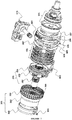
- FIG. 7 is a perspective view showing the structures of a clearance control swash plate device and a single-shaft two-speed drive system with a friction clutch applied thereto according to another embodiment of the present invention.
- the plane disks 402 and clutch disks 403 of a disk set 401 may be cone clutches. Since the cone clutch corresponds to a well-known technology, a detail description thereof is omitted.
- FIG. 8 is a partially cutaway view showing the disk set and the clearance control swash plate device according to the other embodiment of the present invention.
- the clearance control swash plate device and the single-shaft two-speed drive system with a friction clutch applied thereto are improved over the conventional technologies.
- the at least one planetary gear set, the reduction set, the disk set, the clearance control swash plate device, the pivot gear set, and the differential are densely disposed on the same axial line. Accordingly, an installation space can be reduced by decreasing the volumes of the clearance control swash plate device and the single-shaft two-speed drive system, efficiency can be improved by reducing the number of parts, costs and weight, noise and vibration can be reduced due to the characteristic in which the power transfer and the gear shift action are performed on the single same axial line, and fuel efficiency can be improved by extending a reduction range. Furthermore, the reduction set and the clearance control swash plate device are provided, thereby achieving the effect of enabling reduction to be actively performed and the effect of overcoming the problem in which generated power is blocked during the reduction.
Landscapes
- Engineering & Computer Science (AREA)
- General Engineering & Computer Science (AREA)
- Mechanical Engineering (AREA)
- Chemical & Material Sciences (AREA)
- Combustion & Propulsion (AREA)
- Transportation (AREA)
- Physics & Mathematics (AREA)
- Electromagnetism (AREA)
- Retarders (AREA)
- Mechanical Operated Clutches (AREA)
Applications Claiming Priority (1)
| Application Number | Priority Date | Filing Date | Title |
|---|---|---|---|
| KR1020170057912A KR102020104B1 (ko) | 2017-05-10 | 2017-05-10 | 클리어런스 제어 사판 장치 및 마찰 클러치 적용 단일 축 2속 구동 시스템 |
Publications (2)
| Publication Number | Publication Date |
|---|---|
| EP3401563A1 true EP3401563A1 (de) | 2018-11-14 |
| EP3401563B1 EP3401563B1 (de) | 2021-05-19 |
Family
ID=59337473
Family Applications (1)
| Application Number | Title | Priority Date | Filing Date |
|---|---|---|---|
| EP17180455.2A Active EP3401563B1 (de) | 2017-05-10 | 2017-07-10 | Abstandskontrolle-taumelscheibenvorrichtung und einwelliges zweiganggetriebesystem mit darauf aufgebrachter rutschkupplung |
Country Status (4)
| Country | Link |
|---|---|
| US (1) | US10253858B2 (de) |
| EP (1) | EP3401563B1 (de) |
| KR (1) | KR102020104B1 (de) |
| CN (1) | CN107165956B (de) |
Cited By (1)
| Publication number | Priority date | Publication date | Assignee | Title |
|---|---|---|---|---|
| EP3919780A4 (de) * | 2019-02-01 | 2022-12-14 | Univance Corporation | Übertragungsvorrichtung |
Families Citing this family (3)
| Publication number | Priority date | Publication date | Assignee | Title |
|---|---|---|---|---|
| AT520296B1 (de) * | 2017-11-10 | 2019-03-15 | Avl Commercial Driveline & Tractor Eng Gmbh | Schaltvorrichtung für ein getriebe |
| CN108131448A (zh) * | 2018-02-09 | 2018-06-08 | 华北理工大学 | 电动汽车两挡变速箱换挡执行机构 |
| TWI757100B (zh) * | 2021-02-22 | 2022-03-01 | 姚立和 | 離合器結構 |
Citations (8)
| Publication number | Priority date | Publication date | Assignee | Title |
|---|---|---|---|---|
| KR100195022B1 (ko) | 1995-07-25 | 1999-06-15 | 양재신 | 전기 자동차용 구동장치 |
| KR100531444B1 (ko) | 2004-03-30 | 2005-11-28 | 씨 와이 뮤텍 주식회사 | 변속기용 싱크로나이저링 |
| US20050279601A1 (en) * | 2004-06-17 | 2005-12-22 | Thomas Tuday | Torque-transmitting mechanisms for a planetary transmission |
| WO2012145580A1 (en) * | 2011-04-20 | 2012-10-26 | GKN Driveline Newton, LLC | Power transfer unit |
| KR101341384B1 (ko) | 2009-09-14 | 2013-12-13 | 호르비거 안트립스테크닉 홀딩 게엠베하 | 2개의 동기화 링을 포함하는 어셈블리 유닛 |
| KR101374872B1 (ko) | 2012-11-20 | 2014-03-17 | 씨 와이 뮤텍 주식회사 | 전기자동차의 드라이브 유닛장치 |
| DE102015206748A1 (de) * | 2014-04-16 | 2015-10-22 | Warn Industries, Inc. | Motorbetriebenes Verbindungstrennersystem und Betriebsverfahren |
| US20150321554A1 (en) * | 2014-05-08 | 2015-11-12 | Gkn Driveline North America, Inc. | Vehicle power transfer unit (ptu) disconnect assembly |
Family Cites Families (7)
| Publication number | Priority date | Publication date | Assignee | Title |
|---|---|---|---|---|
| JP2004125149A (ja) * | 2002-08-05 | 2004-04-22 | Nsk Ltd | クラッチ装置 |
| US6830141B1 (en) * | 2003-05-23 | 2004-12-14 | General Motors Corporation | Friction-based clutch actuation system |
| JP5023030B2 (ja) * | 2008-09-16 | 2012-09-12 | Gknドライブラインジャパン株式会社 | 摩擦クラッチの締結機構および該機構を備えるディファレンシャル装置 |
| JP6040572B2 (ja) * | 2012-05-24 | 2016-12-07 | 株式会社ジェイテクト | 駆動力伝達制御装置 |
| KR101378686B1 (ko) * | 2012-08-21 | 2014-03-27 | 현대위아 주식회사 | 차량의 다판 클러치의 구동장치 |
| CN204547733U (zh) * | 2015-03-07 | 2015-08-12 | 合肥工业大学 | 单驱动电机的插电式混合动力汽车的两挡变速驱动系统 |
| JP6644499B2 (ja) * | 2015-08-25 | 2020-02-12 | Ntn株式会社 | 自動クラッチ装置 |
-
2017
- 2017-05-10 KR KR1020170057912A patent/KR102020104B1/ko active IP Right Grant
- 2017-06-29 CN CN201710516961.1A patent/CN107165956B/zh active Active
- 2017-07-04 US US15/641,310 patent/US10253858B2/en active Active
- 2017-07-10 EP EP17180455.2A patent/EP3401563B1/de active Active
Patent Citations (8)
| Publication number | Priority date | Publication date | Assignee | Title |
|---|---|---|---|---|
| KR100195022B1 (ko) | 1995-07-25 | 1999-06-15 | 양재신 | 전기 자동차용 구동장치 |
| KR100531444B1 (ko) | 2004-03-30 | 2005-11-28 | 씨 와이 뮤텍 주식회사 | 변속기용 싱크로나이저링 |
| US20050279601A1 (en) * | 2004-06-17 | 2005-12-22 | Thomas Tuday | Torque-transmitting mechanisms for a planetary transmission |
| KR101341384B1 (ko) | 2009-09-14 | 2013-12-13 | 호르비거 안트립스테크닉 홀딩 게엠베하 | 2개의 동기화 링을 포함하는 어셈블리 유닛 |
| WO2012145580A1 (en) * | 2011-04-20 | 2012-10-26 | GKN Driveline Newton, LLC | Power transfer unit |
| KR101374872B1 (ko) | 2012-11-20 | 2014-03-17 | 씨 와이 뮤텍 주식회사 | 전기자동차의 드라이브 유닛장치 |
| DE102015206748A1 (de) * | 2014-04-16 | 2015-10-22 | Warn Industries, Inc. | Motorbetriebenes Verbindungstrennersystem und Betriebsverfahren |
| US20150321554A1 (en) * | 2014-05-08 | 2015-11-12 | Gkn Driveline North America, Inc. | Vehicle power transfer unit (ptu) disconnect assembly |
Cited By (1)
| Publication number | Priority date | Publication date | Assignee | Title |
|---|---|---|---|---|
| EP3919780A4 (de) * | 2019-02-01 | 2022-12-14 | Univance Corporation | Übertragungsvorrichtung |
Also Published As
| Publication number | Publication date |
|---|---|
| EP3401563B1 (de) | 2021-05-19 |
| US20180328474A1 (en) | 2018-11-15 |
| CN107165956B (zh) | 2021-04-06 |
| CN107165956A (zh) | 2017-09-15 |
| US10253858B2 (en) | 2019-04-09 |
| KR102020104B1 (ko) | 2019-11-05 |
| KR20180124177A (ko) | 2018-11-21 |
Similar Documents
| Publication | Publication Date | Title |
|---|---|---|
| CN108136889B (zh) | Cvt差速器 | |
| US7384366B2 (en) | Transfer case with torque synchronizer clutching | |
| EP3401563B1 (de) | Abstandskontrolle-taumelscheibenvorrichtung und einwelliges zweiganggetriebesystem mit darauf aufgebrachter rutschkupplung | |
| CN110091702B (zh) | 动力传递装置 | |
| US10323693B2 (en) | Disconnect system for an axle | |
| EP2110582B1 (de) | Differentialvorrichtung für fahrzeug | |
| US10563704B2 (en) | Locking transfer case | |
| JPS627419B2 (de) | ||
| US20180187767A1 (en) | Power transmission system for vehicle | |
| EP3284971B1 (de) | Zweigangantriebssystem mit einzelwelle | |
| KR101837458B1 (ko) | 동력전달 장치, 이를 포함하는 차량 | |
| US10001206B2 (en) | Power transmission system for vehicle | |
| WO2018064505A1 (en) | Multi speed transmission | |
| CN108691926B (zh) | 扭矩限制器 | |
| CN102410343A (zh) | 具有倒档齿轮制动器的变速器 | |
| CN113119886A (zh) | 电动车辆 | |
| EP3740701B1 (de) | Getriebevorrichtung und getriebeanordnung | |
| US10436304B2 (en) | Power transmission system for vehicle | |
| EP2677189A1 (de) | Getriebe für ein Fahrzeug und Fahrzeug mit einem solchen Getriebe | |
| CN108688464B (zh) | 混合分动箱 | |
| JP3568968B2 (ja) | デファレンシャル装置 | |
| KR101837459B1 (ko) | 동력전달 장치의 작동 제어 방법 | |
| JP5039647B2 (ja) | 動力伝達装置 | |
| KR101841401B1 (ko) | 동력전달 장치 및 이를 포함하는 차량 | |
| JP4516655B2 (ja) | 発進クラッチ |
Legal Events
| Date | Code | Title | Description |
|---|---|---|---|
| PUAI | Public reference made under article 153(3) epc to a published international application that has entered the european phase |
Free format text: ORIGINAL CODE: 0009012 |
|
| STAA | Information on the status of an ep patent application or granted ep patent |
Free format text: STATUS: THE APPLICATION HAS BEEN PUBLISHED |
|
| AK | Designated contracting states |
Kind code of ref document: A1 Designated state(s): AL AT BE BG CH CY CZ DE DK EE ES FI FR GB GR HR HU IE IS IT LI LT LU LV MC MK MT NL NO PL PT RO RS SE SI SK SM TR |
|
| AX | Request for extension of the european patent |
Extension state: BA ME |
|
| STAA | Information on the status of an ep patent application or granted ep patent |
Free format text: STATUS: REQUEST FOR EXAMINATION WAS MADE |
|
| 17P | Request for examination filed |
Effective date: 20190514 |
|
| RBV | Designated contracting states (corrected) |
Designated state(s): AL AT BE BG CH CY CZ DE DK EE ES FI FR GB GR HR HU IE IS IT LI LT LU LV MC MK MT NL NO PL PT RO RS SE SI SK SM TR |
|
| GRAP | Despatch of communication of intention to grant a patent |
Free format text: ORIGINAL CODE: EPIDOSNIGR1 |
|
| STAA | Information on the status of an ep patent application or granted ep patent |
Free format text: STATUS: GRANT OF PATENT IS INTENDED |
|
| INTG | Intention to grant announced |
Effective date: 20201217 |
|
| GRAS | Grant fee paid |
Free format text: ORIGINAL CODE: EPIDOSNIGR3 |
|
| GRAA | (expected) grant |
Free format text: ORIGINAL CODE: 0009210 |
|
| STAA | Information on the status of an ep patent application or granted ep patent |
Free format text: STATUS: THE PATENT HAS BEEN GRANTED |
|
| AK | Designated contracting states |
Kind code of ref document: B1 Designated state(s): AL AT BE BG CH CY CZ DE DK EE ES FI FR GB GR HR HU IE IS IT LI LT LU LV MC MK MT NL NO PL PT RO RS SE SI SK SM TR |
|
| REG | Reference to a national code |
Ref country code: GB Ref legal event code: FG4D |
|
| REG | Reference to a national code |
Ref country code: CH Ref legal event code: EP |
|
| REG | Reference to a national code |
Ref country code: DE Ref legal event code: R096 Ref document number: 602017038728 Country of ref document: DE |
|
| REG | Reference to a national code |
Ref country code: AT Ref legal event code: REF Ref document number: 1394264 Country of ref document: AT Kind code of ref document: T Effective date: 20210615 |
|
| REG | Reference to a national code |
Ref country code: IE Ref legal event code: FG4D |
|
| REG | Reference to a national code |
Ref country code: LT Ref legal event code: MG9D |
|
| REG | Reference to a national code |
Ref country code: AT Ref legal event code: MK05 Ref document number: 1394264 Country of ref document: AT Kind code of ref document: T Effective date: 20210519 |
|
| REG | Reference to a national code |
Ref country code: NL Ref legal event code: MP Effective date: 20210519 |
|
| PG25 | Lapsed in a contracting state [announced via postgrant information from national office to epo] |
Ref country code: HR Free format text: LAPSE BECAUSE OF FAILURE TO SUBMIT A TRANSLATION OF THE DESCRIPTION OR TO PAY THE FEE WITHIN THE PRESCRIBED TIME-LIMIT Effective date: 20210519 Ref country code: AT Free format text: LAPSE BECAUSE OF FAILURE TO SUBMIT A TRANSLATION OF THE DESCRIPTION OR TO PAY THE FEE WITHIN THE PRESCRIBED TIME-LIMIT Effective date: 20210519 Ref country code: BG Free format text: LAPSE BECAUSE OF FAILURE TO SUBMIT A TRANSLATION OF THE DESCRIPTION OR TO PAY THE FEE WITHIN THE PRESCRIBED TIME-LIMIT Effective date: 20210819 Ref country code: FI Free format text: LAPSE BECAUSE OF FAILURE TO SUBMIT A TRANSLATION OF THE DESCRIPTION OR TO PAY THE FEE WITHIN THE PRESCRIBED TIME-LIMIT Effective date: 20210519 Ref country code: LT Free format text: LAPSE BECAUSE OF FAILURE TO SUBMIT A TRANSLATION OF THE DESCRIPTION OR TO PAY THE FEE WITHIN THE PRESCRIBED TIME-LIMIT Effective date: 20210519 |
|
| PG25 | Lapsed in a contracting state [announced via postgrant information from national office to epo] |
Ref country code: LV Free format text: LAPSE BECAUSE OF FAILURE TO SUBMIT A TRANSLATION OF THE DESCRIPTION OR TO PAY THE FEE WITHIN THE PRESCRIBED TIME-LIMIT Effective date: 20210519 Ref country code: IS Free format text: LAPSE BECAUSE OF FAILURE TO SUBMIT A TRANSLATION OF THE DESCRIPTION OR TO PAY THE FEE WITHIN THE PRESCRIBED TIME-LIMIT Effective date: 20210919 Ref country code: GR Free format text: LAPSE BECAUSE OF FAILURE TO SUBMIT A TRANSLATION OF THE DESCRIPTION OR TO PAY THE FEE WITHIN THE PRESCRIBED TIME-LIMIT Effective date: 20210820 Ref country code: NO Free format text: LAPSE BECAUSE OF FAILURE TO SUBMIT A TRANSLATION OF THE DESCRIPTION OR TO PAY THE FEE WITHIN THE PRESCRIBED TIME-LIMIT Effective date: 20210819 Ref country code: PL Free format text: LAPSE BECAUSE OF FAILURE TO SUBMIT A TRANSLATION OF THE DESCRIPTION OR TO PAY THE FEE WITHIN THE PRESCRIBED TIME-LIMIT Effective date: 20210519 Ref country code: PT Free format text: LAPSE BECAUSE OF FAILURE TO SUBMIT A TRANSLATION OF THE DESCRIPTION OR TO PAY THE FEE WITHIN THE PRESCRIBED TIME-LIMIT Effective date: 20210920 Ref country code: SE Free format text: LAPSE BECAUSE OF FAILURE TO SUBMIT A TRANSLATION OF THE DESCRIPTION OR TO PAY THE FEE WITHIN THE PRESCRIBED TIME-LIMIT Effective date: 20210519 Ref country code: RS Free format text: LAPSE BECAUSE OF FAILURE TO SUBMIT A TRANSLATION OF THE DESCRIPTION OR TO PAY THE FEE WITHIN THE PRESCRIBED TIME-LIMIT Effective date: 20210519 |
|
| PG25 | Lapsed in a contracting state [announced via postgrant information from national office to epo] |
Ref country code: NL Free format text: LAPSE BECAUSE OF FAILURE TO SUBMIT A TRANSLATION OF THE DESCRIPTION OR TO PAY THE FEE WITHIN THE PRESCRIBED TIME-LIMIT Effective date: 20210519 |
|
| PG25 | Lapsed in a contracting state [announced via postgrant information from national office to epo] |
Ref country code: RO Free format text: LAPSE BECAUSE OF FAILURE TO SUBMIT A TRANSLATION OF THE DESCRIPTION OR TO PAY THE FEE WITHIN THE PRESCRIBED TIME-LIMIT Effective date: 20210519 Ref country code: ES Free format text: LAPSE BECAUSE OF FAILURE TO SUBMIT A TRANSLATION OF THE DESCRIPTION OR TO PAY THE FEE WITHIN THE PRESCRIBED TIME-LIMIT Effective date: 20210519 Ref country code: CZ Free format text: LAPSE BECAUSE OF FAILURE TO SUBMIT A TRANSLATION OF THE DESCRIPTION OR TO PAY THE FEE WITHIN THE PRESCRIBED TIME-LIMIT Effective date: 20210519 Ref country code: EE Free format text: LAPSE BECAUSE OF FAILURE TO SUBMIT A TRANSLATION OF THE DESCRIPTION OR TO PAY THE FEE WITHIN THE PRESCRIBED TIME-LIMIT Effective date: 20210519 Ref country code: DK Free format text: LAPSE BECAUSE OF FAILURE TO SUBMIT A TRANSLATION OF THE DESCRIPTION OR TO PAY THE FEE WITHIN THE PRESCRIBED TIME-LIMIT Effective date: 20210519 Ref country code: SK Free format text: LAPSE BECAUSE OF FAILURE TO SUBMIT A TRANSLATION OF THE DESCRIPTION OR TO PAY THE FEE WITHIN THE PRESCRIBED TIME-LIMIT Effective date: 20210519 Ref country code: SM Free format text: LAPSE BECAUSE OF FAILURE TO SUBMIT A TRANSLATION OF THE DESCRIPTION OR TO PAY THE FEE WITHIN THE PRESCRIBED TIME-LIMIT Effective date: 20210519 |
|
| REG | Reference to a national code |
Ref country code: DE Ref legal event code: R097 Ref document number: 602017038728 Country of ref document: DE |
|
| REG | Reference to a national code |
Ref country code: CH Ref legal event code: PL |
|
| PLBE | No opposition filed within time limit |
Free format text: ORIGINAL CODE: 0009261 |
|
| STAA | Information on the status of an ep patent application or granted ep patent |
Free format text: STATUS: NO OPPOSITION FILED WITHIN TIME LIMIT |
|
| PG25 | Lapsed in a contracting state [announced via postgrant information from national office to epo] |
Ref country code: MC Free format text: LAPSE BECAUSE OF FAILURE TO SUBMIT A TRANSLATION OF THE DESCRIPTION OR TO PAY THE FEE WITHIN THE PRESCRIBED TIME-LIMIT Effective date: 20210519 |
|
| REG | Reference to a national code |
Ref country code: BE Ref legal event code: MM Effective date: 20210731 |
|
| 26N | No opposition filed |
Effective date: 20220222 |
|
| GBPC | Gb: european patent ceased through non-payment of renewal fee |
Effective date: 20210819 |
|
| PG25 | Lapsed in a contracting state [announced via postgrant information from national office to epo] |
Ref country code: LI Free format text: LAPSE BECAUSE OF NON-PAYMENT OF DUE FEES Effective date: 20210731 Ref country code: CH Free format text: LAPSE BECAUSE OF NON-PAYMENT OF DUE FEES Effective date: 20210731 |
|
| PG25 | Lapsed in a contracting state [announced via postgrant information from national office to epo] |
Ref country code: IS Free format text: LAPSE BECAUSE OF FAILURE TO SUBMIT A TRANSLATION OF THE DESCRIPTION OR TO PAY THE FEE WITHIN THE PRESCRIBED TIME-LIMIT Effective date: 20210919 Ref country code: LU Free format text: LAPSE BECAUSE OF NON-PAYMENT OF DUE FEES Effective date: 20210710 Ref country code: FR Free format text: LAPSE BECAUSE OF NON-PAYMENT OF DUE FEES Effective date: 20210719 Ref country code: AL Free format text: LAPSE BECAUSE OF FAILURE TO SUBMIT A TRANSLATION OF THE DESCRIPTION OR TO PAY THE FEE WITHIN THE PRESCRIBED TIME-LIMIT Effective date: 20210519 |
|
| PG25 | Lapsed in a contracting state [announced via postgrant information from national office to epo] |
Ref country code: IT Free format text: LAPSE BECAUSE OF FAILURE TO SUBMIT A TRANSLATION OF THE DESCRIPTION OR TO PAY THE FEE WITHIN THE PRESCRIBED TIME-LIMIT Effective date: 20210519 Ref country code: IE Free format text: LAPSE BECAUSE OF NON-PAYMENT OF DUE FEES Effective date: 20210710 Ref country code: GB Free format text: LAPSE BECAUSE OF NON-PAYMENT OF DUE FEES Effective date: 20210819 Ref country code: BE Free format text: LAPSE BECAUSE OF NON-PAYMENT OF DUE FEES Effective date: 20210731 |
|
| PG25 | Lapsed in a contracting state [announced via postgrant information from national office to epo] |
Ref country code: CY Free format text: LAPSE BECAUSE OF FAILURE TO SUBMIT A TRANSLATION OF THE DESCRIPTION OR TO PAY THE FEE WITHIN THE PRESCRIBED TIME-LIMIT Effective date: 20210519 |
|
| PG25 | Lapsed in a contracting state [announced via postgrant information from national office to epo] |
Ref country code: HU Free format text: LAPSE BECAUSE OF FAILURE TO SUBMIT A TRANSLATION OF THE DESCRIPTION OR TO PAY THE FEE WITHIN THE PRESCRIBED TIME-LIMIT; INVALID AB INITIO Effective date: 20170710 |
|
| PGFP | Annual fee paid to national office [announced via postgrant information from national office to epo] |
Ref country code: DE Payment date: 20230721 Year of fee payment: 7 |
|
| PG25 | Lapsed in a contracting state [announced via postgrant information from national office to epo] |
Ref country code: MK Free format text: LAPSE BECAUSE OF FAILURE TO SUBMIT A TRANSLATION OF THE DESCRIPTION OR TO PAY THE FEE WITHIN THE PRESCRIBED TIME-LIMIT Effective date: 20210519 |
|
| PG25 | Lapsed in a contracting state [announced via postgrant information from national office to epo] |
Ref country code: TR Free format text: LAPSE BECAUSE OF FAILURE TO SUBMIT A TRANSLATION OF THE DESCRIPTION OR TO PAY THE FEE WITHIN THE PRESCRIBED TIME-LIMIT Effective date: 20210519 |