EP3401455B1 - Folienband - Google Patents
Folienband Download PDFInfo
- Publication number
- EP3401455B1 EP3401455B1 EP18170906.4A EP18170906A EP3401455B1 EP 3401455 B1 EP3401455 B1 EP 3401455B1 EP 18170906 A EP18170906 A EP 18170906A EP 3401455 B1 EP3401455 B1 EP 3401455B1
- Authority
- EP
- European Patent Office
- Prior art keywords
- self
- tape
- state
- carrier material
- adhesive layer
- Prior art date
- Legal status (The legal status is an assumption and is not a legal conclusion. Google has not performed a legal analysis and makes no representation as to the accuracy of the status listed.)
- Active
Links
Images

Classifications
-
- E—FIXED CONSTRUCTIONS
- E04—BUILDING
- E04B—GENERAL BUILDING CONSTRUCTIONS; WALLS, e.g. PARTITIONS; ROOFS; FLOORS; CEILINGS; INSULATION OR OTHER PROTECTION OF BUILDINGS
- E04B1/00—Constructions in general; Structures which are not restricted either to walls, e.g. partitions, or floors or ceilings or roofs
- E04B1/62—Insulation or other protection; Elements or use of specified material therefor
- E04B1/66—Sealings
- E04B1/68—Sealings of joints, e.g. expansion joints
- E04B1/6812—Compressable seals of solid form
-
- E—FIXED CONSTRUCTIONS
- E06—DOORS, WINDOWS, SHUTTERS, OR ROLLER BLINDS IN GENERAL; LADDERS
- E06B—FIXED OR MOVABLE CLOSURES FOR OPENINGS IN BUILDINGS, VEHICLES, FENCES OR LIKE ENCLOSURES IN GENERAL, e.g. DOORS, WINDOWS, BLINDS, GATES
- E06B1/00—Border constructions of openings in walls, floors, or ceilings; Frames to be rigidly mounted in such openings
- E06B1/62—Tightening or covering joints between the border of openings and the frame or between contiguous frames
- E06B2001/626—Tightening or covering joints between the border of openings and the frame or between contiguous frames comprising expanding foam strips
Definitions
- the invention relates to a self-adhesive tape suitable and intended for sealing joints, comprising at least a first layer of a carrier material, which has two opposite outer surfaces of the carrier material, wherein at least one of these outer surfaces is at least partially coated with a self-adhesive layer, wherein in the first State an outer surface is completely covered by the self-adhesive layer at least in a central region with respect to the width direction of the tape.
- the invention also relates to a method for producing a self-adhesive tape suitable and intended for sealing joints.
- Tapes for sealing joints are known from the prior art.
- such tapes are used in house construction for sealing so-called construction connection joints, ie joints between assembled components.
- construction connection joints ie joints between assembled components.
- RAL guidelines for planning and installing windows and front doors, March 2010, Chapter 6.4.4, such tapes are also referred to as joint sealing tapes.
- building connection joints are, for example, joints between masonry and a window or door frame.
- Foil tapes can be made up of several layers and usually have a narrow self-adhesive strip in the area of one long side, with which the foil tape which can be connected to a long side area on the window or door frame.
- the longitudinal side area lying opposite in the width direction of the film strip is connected to the masonry, for example an outer wall or a facade.
- the wall-side connection is usually made by means of an adhesive, which is either designed as a self-adhesive strip on the film or which is applied separately to the masonry.
- the tape can later be further fixed by embedding it in the plaster.
- Examples of such tapes are, for example, from the patent applications DE 10 2015 202 882 A1 and EP 2 692 959 A1 known.
- the sealing tape has on one side two self-adhesive strips which are spaced apart from one another and extend along the outer longitudinal side regions of the tape. Provision is made for one of these self-adhesive strips to be connected to a foam body which fills a gap, for example between a window frame and a window reveal. The space between the self-adhesive strips is placed on one side of the foam body without being connected to it, and the other self-adhesive strip is then connected to the window frame. The area not provided with self-adhesive strips thus forms a sealing film which can inhibit the diffusion of water vapor through the foam body.
- the Patent application EP 2 692 959 A1 also discloses a foil tape for sealing joints between assembled building elements in house construction.
- the film tape comprises a non-perforated functional membrane made of a film which has either a self-adhesive layer applied over the entire surface or two self-adhesive strips which are spaced apart from one another in the transverse direction, have different widths and run in the longitudinal direction.
- the functional membrane can be glued to the two outer sides of the respective building elements, so that the film also covers the joint in between.
- the functional membrane is preferably a moisture-variable polymer film whose water vapor diffusion coefficient changes depending on the ambient humidity.
- the spaced-apart self-adhesive strips must each be applied separately, which requires special precautions with regard to the accuracy of the positioning of the self-adhesive strips.
- self-adhesive strips are usually applied to large rolls of film in the width of use.
- Self-adhesive strips spaced apart from one another along the broad side of a sealing tape can, due to their material thickness, lead to irregularities and thus to instability of the roll, especially if the tape is wound up into a roll and the additional material thickness of the individual self-adhesive strips arranged one above the other adds up.
- the present invention is therefore based on the object of providing a self-adhesive tape which is suitable and specific for sealing joints and which does not have the abovementioned disadvantages, or at least reduces them. It is also an object of the invention to provide a simplified method for producing a self-adhesive tape suitable and intended for sealing joints.
- An essential aspect of the invention is therefore a suitable and specific self-adhesive tape for sealing joints, which comprises at least a first layer of a carrier material, which has two opposite outer surfaces of the carrier material, wherein at least one of these outer surfaces is at least partially coated with a self-adhesive layer, wherein in the first state an outer surface is completely covered by the self-adhesive layer at least in a central region with respect to the width direction of the tape. It is also essential that the tape can be transferred from a first state to a second state, the tape having a greater width in the second state than in the first state and in the second state the self-adhesive layer covers the outer surface at least in the central region with respect to the width direction of the tape is not completely covered.
- the outer surfaces of the carrier material are understood to be those surfaces that are in contact with the environment or with another component of the sealing tape.
- the carrier material preferably comprises a film or a fleece.
- the carrier material is a fleece/film composite in a preferred embodiment. This is preferably multi-layered, for example 2-ply (e.g. fleece/foil) or 3-ply (e.g. fleece/foil/fleece).
- the film it is preferable for the film to be variable in terms of water vapor diffusion in such a composite.
- Such a carrier material usually has only a small height and extends essentially in the longitudinal direction and width direction.
- the outer surfaces of the carrier material are therefore understood to mean those (outer) surfaces which extend on both sides of the carrier material along the width and longitudinal direction of the sealing tape.
- internal surfaces of the carrier material are understood to be surfaces that are not in contact with the environment or with another component of the sealing tape. Such surfaces can be caused, for example, by folding the carrier material, whereby first surfaces of the carrier material come to rest on second surfaces of the carrier material, so that they cannot be contacted by other components of the sealing tape (apart from the carrier material itself).
- the sealing tape is at least partially open to diffusion, contact between the internal surfaces and other components (not directly related to the sealing tape) such as air, steam, other gases, water or other solvents cannot be ruled out.
- the carrier material itself can consist of several components.
- a fleece could include different types of fibers, through which the product properties could be adjusted in a targeted manner.
- carrier materials are conceivable which comprise a composite of one or more films and/or additionally have one or more fleece(s).
- the outer surface of such a multi-component carrier material is to be understood in each case as the outermost surface of the composite that forms the carrier material. Accordingly, an inner surface of such a multi-component carrier material is a surface that is not in contact with the environment or a other component of the sealing tape (e.g. a self-adhesive layer). However, contact with another layer/component of the carrier material itself is possible.
- an inner surface of a multi-component carrier material also represents a surface of the carrier material in its entirety and is not an area between individual layers / components of the carrier material itself. Inner surfaces of a carrier material are therefore to be distinguished from inner surfaces of the carrier material , which are formed, for example, by fibers of a fleece or any additional components (e.g. activated carbon) contained in the carrier material with a very large internal surface area (BET).
- BET internal surface area
- the multiple layers of the carrier material are arranged one above the other at least in the central area. In this area, therefore, a plurality of layers of the carrier material preferably lie one on top of the other in such a way that surfaces of the carrier material make contact. These surfaces are no longer accessible to other components of the sealing tape and therefore form internal surfaces. Due to the at least partial gas permeability of the belt, gases such as air or water vapor can also reach these inner surfaces.
- the central area is that area of the belt in which, at least in the first state, several layers of the carrier material are arranged one on top of the other. Internal surfaces of the carrier material preferably make contact in this area.
- the extension of the center portion in the width direction of the tape is not limited. It is conceivable that the central area extends widthwise to the immediate vicinity of the edges of the band, or even to one or both edges of the band.
- the carrier material has at least one fold in the central area, in which several layers of the carrier material are arranged one on top of the other.
- the carrier material is at least in the central area has a Z-shaped course in cross-section along the width direction of the strip in sections.
- the carrier material is preferably arranged, at least in sections, in at least three, more preferably exactly three layers lying one on top of the other. In such an arrangement, surfaces of the carrier material contact one another so that they are no longer accessible to other components of the belt. They thus form internal surfaces of the carrier material. If the z-shaped course is produced by folding the carrier material, as is preferably provided for in the process, surfaces of the carrier material which were previously arranged adjacent to one another and were preferably outer surfaces of the carrier material come to rest on one another.
- the central area of the carrier material has a z-shaped profile in cross section along the width direction of the tape not only in a single section, but in several sections. More preferably, it is provided that the z-shaped course in at least some sections is a mirror image of the course in other sections. More preferably, a section with a z-shaped profile is followed by a section with a profile whose shape follows the mirror image of a "z".
- a configuration of this type enables a higher degree of symmetry of the strip along its width direction. In particular, it is conceivable that the strip is mirror-symmetrical with respect to its center in the width direction.
- the profile does not have to strictly follow the design of the letter “z”, but that this geometry can also be distorted, compressed or twisted. Such modifications explicitly also represent variants of the invention. Due to the usually small height of a strip, strong compression of the “z” in the height direction is possible and is provided in preferred embodiments.
- the carrier material has at least one surface in the central region, which is an inner surface in the first state and part of the outer surface of the tape in the second state.
- the band is preferably deformed in such a way that at least parts of the surfaces of the carrier material lying on the inside in the first state become parts of the outer surface of the band.
- the transition from the first state to the second state preferably takes place by deformation of the band.
- a deformation of the strip along its width direction is conceivable. More preferably, this reshaping is accompanied by an increase in the extent of the strip in the width direction.
- an at least partial unfolding of this fold is conceivable. The unfolding preferably takes place in the width direction.
- the self-adhesive layer covers at least 80% of an outer surface of the tape in the first state.
- the self-adhesive layer does not have to cover all of the outer surfaces of the tape, but this would also be conceivable with double-sided adhesive tapes.
- the above specification of at least 80% coverage of an outer surface of the strip therefore relates only to one surface of the strip, this surface extending on one side along a width direction and a longitudinal direction of the strip perpendicular thereto.
- the self-adhesive layer preferably covers at least 90%, more preferably at least 95%, of this outer surface of the tape.
- the self-adhesive layer covers this outer surface of the tape over the entire width of the tape.
- This embodiment is particularly preferred because it means that during manufacture of the tape no distinction needs to be made between areas that are to be provided with the self-adhesive layer and those that are not to be covered with a self-adhesive layer.
- an outer surface of the tape which is partially covered with a self-adhesive layer is not covered with a self-adhesive layer over at least 10% in the second state.
- Preferably even at least 15%, more preferably at least 20%, particularly preferably over at least 25% of this surface is not covered with a self-adhesive layer in the second state.
- the area of the outer surface of the tape that is not covered with a self-adhesive layer in the second state extends in the form of a strip along the longitudinal direction of the tape.
- the area of the outer surface not covered with a self-adhesive layer runs between two parallel running strips of a self-adhesive layer, which—more preferably along the lateral edges of the tape—extend in the longitudinal direction of the tape.
- the band preferably the backing material
- the water vapor permeability can preferably be changed as a function of the atmospheric humidity.
- the water vapor permeability is more preferably higher in the wet state, particularly preferably significantly higher than in the dry state.
- the tape and/or the carrier material therefore preferably has a variable sd value.
- the sd value is calculated from the layer thickness of the material multiplied by the water vapor diffusion resistance number of the material and has the unit "m".
- the Sd value is defined in DIN 4108 Part 3 as the air layer thickness equivalent to water vapor diffusion.
- the material's resistance to water vapor diffusion, the so-called ⁇ -value is defined by DIN EN ISO 12572:2001.
- the tape has at least one additional layer, the material of such a layer being selected from a group comprising a film, a fleece, a combination of film and fleece, a fleece lamination, a butyl tape, an aluminum coating, EPDM, an optionally impregnated, optionally compressed foam material strip, a pressure-sensitive adhesive, an acrylate, neoprene, a rubber, in particular styrene-butadiene rubber (SBK), natural rubber, synthetic rubber or chlorinated rubber, or others.
- the material of such a layer being selected from a group comprising a film, a fleece, a combination of film and fleece, a fleece lamination, a butyl tape, an aluminum coating, EPDM, an optionally impregnated, optionally compressed foam material strip, a pressure-sensitive adhesive, an acrylate, neoprene, a rubber, in particular styrene-butadiene rubber (SBK), natural rubber, synthetic rubber or chlorinated rubber,
- the self-adhesive layer is preferably an unsupported self-adhesive layer.
- the self-adhesive layer particularly preferably comprises a self-adhesive composition.
- This self-adhesive is preferably selected from an acrylate, (natural) rubber or another suitable self-adhesive.
- the tape preferably has a width that enables it to be used to seal a joint between a window frame and a window reveal.
- the width is therefore selected so that the tape can bridge a joint and also has areas extending beyond the joint, which allow the tape to be attached to a window frame and/or a window reveal, for example.
- the width of the strip in the second state is selected such that it enables a joint between a window frame and a window reveal to be sealed both on the inside and on the outside of the room. It would thus be possible in this embodiment to use different strips of the same tape on the one hand to seal a joint to the inside of the room and on the other hand also to seal off to the outside of the room. This results in the advantage, for example on a construction site, that only a single tape has to be kept available.
- the band preferably has a width which is in the range of 1-50 cm, preferably 2-40 cm, more preferably 3-30 and particularly preferably in the range of 5-25 cm.
- the tape preferably has at least two self-adhesive strips which are spaced apart from one another and extend along the longitudinal direction of the tape. These preferably run parallel to one another. It is further preferred that at least one self-adhesive strip, preferably two self-adhesive strips, run along a lateral boundary of the carrier material. At least one self-adhesive strip, preferably two self-adhesive strips, preferably forms the lateral boundary of the tape. As an alternative to this, a self-adhesive strip or also two self-adhesive strips can be arranged at a distance from a lateral boundary of the tape. This distance is preferably comparatively small and is in the range of less than 20 mm, preferably less than 10 mm, more preferably less than 5 mm and particularly preferably in the range of 0.05-2 mm.
- the width of the self-adhesive strips of the tape can be adapted to the respective requirements.
- a width of the self-adhesive strips which in the second state is in the range of 1-5 cm, preferably 1.5-12 cm, more preferably 2-10 cm, has proven to be particularly advantageous. This information relates to 1 strip.
- the distance between adjacent self-adhesive strips of the tape in the second state, in which the self-adhesive layer does not completely cover the outer surface of the tape or the carrier material, at least in the middle area with respect to the width direction of the tape, has been found to be in the range of 0.1 - 10 cm, preferably 0.5-8 cm, more preferably 0.75-6 cm, particularly preferably 1-4 cm.
- Another essential aspect of the invention is a method for producing a self-adhesive tape that is suitable and specific for sealing joints and has the features of claim 7.
- step b) an overlapping area of the strip-shaped carrier material is produced, but in step c) the self-adhesive layer is only applied to at least one section of the outer surface of the strip-shaped carrier material lying in the overlapping area, the inner surface of the strip-shaped carrier material in the overlapping area can be separated from the self-adhesive layer remain free.
- step c) the self-adhesive layer is only applied to at least one section of the outer surface of the strip-shaped carrier material lying in the overlapping area, the inner surface of the strip-shaped carrier material in the overlapping area can be separated from the self-adhesive layer remain free.
- the self-adhesive layer can be applied directly to sections of the outer surface of the carrier material. It would also be conceivable for the self-adhesive layer not only to comprise the pressure-sensitive adhesive itself, but also itself to comprise a backing and be in the form of a double-sided adhesive tape, for example. Such a double-sided adhesive tape can be stored, for example, in the form of a roll and applied to the carrier material as required. In some cases, this can be process-related advantages compared to applying the PSA without an additional carrier.
- the separate backing allows for the transition of the tape from the first state to the second state.
- the carrier ensures that in the second State the self-adhesive layer does not cover the entire surface of the outer surface at least in the central region with respect to the width direction of the tape. This is preferably realized in that the separate carrier tears open during the transfer of the tape from the first state to the second state and thus exposes additional, previously inner surfaces of the tape.
- the separate carrier is preferably torn open along the longitudinal direction of the tape.
- a predetermined breaking point can be provided to ensure that the separate carrier tears open as desired during the transfer of the tape from the first state to the second state and surfaces that are not coated with the self-adhesive composition are exposed in the middle region of the tape. This could be realized, for example, by a local reduction in the material content, such as a perforation, a notch or other thinning of the material thickness of the separate carrier.
- At least one further layer is applied to at least one side of the strip-shaped carrier material in addition to the self-adhesive layer.
- this is a further self-adhesive layer.
- Such an additional self-adhesive layer could be used, for example, to connect the tape to the masonry (e.g. a window reveal).
- a self-adhesive layer can be applied in addition to or as an alternative to possible further self-adhesive layers on the side of the carrier material opposite the first self-adhesive layer.
- the further layer can be an insulating material, for example. This could serve, for example, for thermal and/or acoustic insulation.
- additional layers are conceivable that influence at least one property of the tape, which are selected from a group that includes absolute water vapor diffusion, water vapor diffusion as a function of humidity, ability to be plastered over, color, color absorption, strength, UV resistance, transparency, surface structure, Impermeability to driving rain, thermal resilience, tear resistance and others.
- Such an additional layer does not necessarily have to follow the layer of the carrier material directly, even if this is possible and advantageous in some cases.
- the additional layer can, for example, be vapor-deposited, deposited, sprayed on, brushed on, welded on, or through other procedures are applied.
- a surface modification of the carrier material is also conceivable in order to produce the desired layer.
- mechanical surface changes such as roughening, chemical surface changes such as oxidation or reduction reactions, or physical surface treatments such as temperature or charge carrier loading would be conceivable.
- the additional layer it is possible for the additional layer to be connected to the carrier layer not directly but with the aid of a further component. This could be done, for example, by another component such as an adhesive layer.
- a further variant of the method includes the step that the band is transferred from a first state to a second state with an increased width, wherein in the second state surfaces of the carrier material which formed inner surfaces in the overlapping area in the first state form outer surfaces of the band . These are preferably not coated with a self-adhesive layer, at least in sections. In a further preferred variant, these external surfaces of the tape, which were internal surfaces in the first state, are completely free of a self-adhesive layer.
- figure 1 shows a first embodiment of a self-adhesive tape 1 suitable and intended for sealing joints in a first state.
- a carrier layer 2 and a self-adhesive layer 3 are shown. When the finished product is delivered, this is usually covered with a liner (not shown).
- the carrier layer 2 is in figure 1 shown in one piece. However, it would be possible for the carrier layer 2 itself not to be formed in one piece, but rather to be composed of a number of components. For example, it would be conceivable for the carrier layer 2 to be multi-layered and to be a composite of several layers. In the case of functional tapes 1 in particular, a multi-layer structure is advantageous or even necessary in order to provide the desired functionality.
- the carrier layer 2 can have, for example, membranes, coatings, foils, foams, paints and other components. Irrespective of its composition, the support layer 2 has two sides 4, 5 which lie opposite one another. As in figure 1 one side 4 of the self-adhesive layer 3 is shown. For the sake of clarity, the carrier layer 2 and the self-adhesive layer 3 are shown spaced apart from one another. In practice, however, the self-adhesive layer 3 contacts the carrier layer 2.
- the carrier layer 2 has a central region 6 which is arranged at a distance from the ends 7a, 7b of the carrier layer 2 with respect to the width direction B.
- this central region 6 there are several layers of the carrier layer 2 one above the other in the vertical direction H. These layers are shown stretched in the height direction H for better illustration. In practice, each of these layers contacts at least one other of these layers.
- the layers in the central region 6 are arranged in a z-shape. Accordingly, three layers of the carrier layer 2 come to lie on top of one another in the middle region 6 .
- the z-shaped fold of the carrier layer 2 shown in the z-shaped fold shown, surface areas which are arranged on the same side 4 of the carrier layer 2 in the stretched, in this case unfolded state of the carrier layer 2 are surfaces lying on top of each other, so that inner surfaces that can be distinguished from the outer surfaces 8a and 8b 9 available. In contrast to the outer surfaces 8a and 8b, the inner surfaces 9 are not contacted by the self-adhesive layer 3.
- the position of the self-adhesive layer 3 marked with the reference number 10 divides the self-adhesive layer 3 into two different areas 3a and 3b, which differ in that the area 3a contacts the outer surface 8a of the carrier layer 2, whereas the area 3b contacts the outer surface 8b of the carrier layer 2 contacted.
- the inner surfaces 9 of the carrier layer 2 are not contacted by the self-adhesive layer 3—neither from the area 3a nor from the area 3b.
- the band shown is usually in a second state, expanded in the width direction B, which in figure 2 is shown schematically. Due to the expansion in width direction B when the tape is transferred from the first to the second state and the adhesion of the two different areas 3a and 3b of the self-adhesive layer 3 to the outer surfaces 8a and 8b of the carrier layer 2, the self-adhesive layer 3 breaks in the area of the in figure 1 with the reference numeral 10 marked position, whereby the end points 10a and 10b of the self-adhesive layer 3 arise.
- the layers of the carrier layer 2 arranged one above the other in the height direction H in the first state can be separated from one another in such a way that the inner surfaces 9 in the first state come to lie next to one another and become outer surfaces of the tape 1 , which are not covered by the self-adhesive layer 3.
- the tape 1 between the end points 10a and 10b of the self-adhesive layer 3 in the second state therefore has no self-adhesive layer 3.
- Such an area is particularly advantageous when the tape is installed—for example for sealing a joint between the window frame and the window reveal—if, for example, displacements of these elements relative to one another must be expected under the influence of heat.
- such a range offers advantages in terms of to an easier installation of the tape, in particular when inserting the tape - or the areas not covered with the self-adhesive layer 3 in corners.
- FIG 3 Another possible embodiment of the self-adhesive tape suitable and intended for sealing joints in a first state is in figure 3 shown.
- the central region 6 is greatly widened in the width direction B of the strip 1 .
- This can be realized by two z-shaped folds of the carrier layer 2 arranged opposite one another along the width direction B as a mirror image.
- This embodiment has compared to in figure 1 shown the advantage that the band can be performed in its entirety symmetrically with respect to its center M in the width direction B. This is advantageous in particular in the case of the usual packaging of a tape 1 in roll form, since all areas of the tape can have the same height in the vertical direction H in the first state.
- such a configuration also makes it possible to greatly enlarge the central region 6 and the surface portions 9 not provided with the self-adhesive layer compared to the surface portions 3a, 3b provided with the self-adhesive layer 3.
- a width ratio of the surface portions 9 not provided with the self-adhesive layer to the surface portions 3a, 3b provided with the self-adhesive layer 3 of 2:1 would theoretically be possible. In practice, however, it has been shown that this width ratio cannot be realized, since in practice it should be avoided that the folds 11a and 11b should be arranged in the vicinity of the ends 7a, 7b of the carrier layer 2.
- FIG. 3 shows an example of such an embodiment which is symmetrical about the center M in the width direction B.
- the identical number of folds of the same type, but arranged as a mirror image are provided on both sides with respect to the center M in the width direction B.
- deviations from this symmetrical geometry are possible, for example in order to adapt the positioning of the surface portion 9 in the width direction of the tape that is not provided with the self-adhesive layer to specific requirements.
- the carrier layer 2 is folded several times, in which several z-shaped folds, for example, come to lie one above the other in the height direction H in the central region 6 .
- a distance between the inside folds 12a and 12b is explicitly provided, since this allows a glue point arranged in this gap to be connected to the self-adhesive layer 3 and thus the folded composite in the area between the inside folds 12a and 12b additionally stabilized with respect to the self-adhesive layer 3.
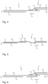
- FIG. 4 Another particularly preferred embodiment of a self-adhesive tape suitable and intended for sealing joints in a first state is in figure 4 shown.
- a self-adhesive layer 3 is not only arranged on the side 5 of the carrier layer 2, but also a further layer 13, for example also a self-adhesive layer, is arranged on the side 4 opposite the side 5 provided with the first self-adhesive layer 3.
- this further layer 13 does not cover an additional z-fold, which would also be possible, however, if an interruption in a self-adhesive layer 13 was also desired on this side 4 of the carrier layer 2 .
- FIG 4 shows the product as delivered, but for the sake of clarity the liner or liners that may be present for covering the self-adhesive layer(s) 3.13 are not shown.
- the carrier layer 2 it is of course possible for the carrier layer 2 to be composed of a number of components, for example a film and a fleece.
- a z-fold is formed in the central area 6 of the carrier layer 2, as in the case of FIG figure 1 illustrated embodiment.
- Outer surfaces 8a and 8b and inner surfaces 9 which are distinguishable therefrom are formed analogously by these.
- the self-adhesive layer 3 can be divided into two different areas 3a and 3b.
- the inner surfaces 9 of the carrier layer 2 are not covered by the self-adhesive layer 3 .
- the further layer 13 has a width of between 10 and 50 mm, preferably 15-30 mm and particularly preferably 18-27 mm. This further layer is preferably arranged at the edge.
- figure 5 shows the in figure 4 illustrated embodiment of the self-adhesive tape suitable and intended for sealing joints in a second state.
- this band is transferred from a first state to a second state.
- the self-adhesive layer 3 is separated into two different areas 3a and 3b at the position previously identified by reference numeral 10, so that between their inner end points 10a and 10b the surfaces 9 lying on the inside in the first state come to lie next to each other and thus become outer surfaces of the tape 1 . These are not covered by the self-adhesive layer 3 in the second state.
- the middle region 6 thus has no self-adhesive layer 3 between the end points 10a and 10b in the second state on side 5 of the carrier layer.
- the change in the width of the strip 1 in the width direction B does not affect the layer 13, which only contacts the outer surface marked with reference number 8c, which is opposite to the outer surface marked with 8a.
- it is available as a further self-adhesive layer 13, for example for gluing the tape 1 to masonry (not shown), for example a window reveal.
- figure 6 shows a further embodiment of the self-adhesive tape suitable and intended for sealing joints in a first state.
- the second state is not shown, but this strip 1 can also be converted into a second state by stretching in the width direction B in an analogous manner.
- This embodiment differs from that shown in FIG. 4 in that the further layer 13 arranged on the outer surface 8c is formed in two parts and a third layer 14 is therefore applied to this surface.
- This layer 14 can be different from the other layer 13 or can be made of the same material. When using different materials, these could be adjusted to have sufficient adhesive force on different substrates, for example. Should the layers 13 and 14 be of identical material, these could also be produced by opening a further z-fold (not shown) from a previously single layer.
- the overall width of the band in the first state is 60-140 mm, more preferably 70-125 mm and most preferably 80-110 mm.
Landscapes
- Engineering & Computer Science (AREA)
- Architecture (AREA)
- Physics & Mathematics (AREA)
- Electromagnetism (AREA)
- Civil Engineering (AREA)
- Structural Engineering (AREA)
- Adhesive Tapes (AREA)
- Adhesives Or Adhesive Processes (AREA)
Applications Claiming Priority (1)
| Application Number | Priority Date | Filing Date | Title |
|---|---|---|---|
| DE102017109688.4A DE102017109688A1 (de) | 2017-05-05 | 2017-05-05 | Folienband mit feuchtevariabler Polymerfolie |
Publications (2)
| Publication Number | Publication Date |
|---|---|
| EP3401455A1 EP3401455A1 (de) | 2018-11-14 |
| EP3401455B1 true EP3401455B1 (de) | 2023-04-26 |
Family
ID=62116756
Family Applications (1)
| Application Number | Title | Priority Date | Filing Date |
|---|---|---|---|
| EP18170906.4A Active EP3401455B1 (de) | 2017-05-05 | 2018-05-04 | Folienband |
Country Status (3)
| Country | Link |
|---|---|
| EP (1) | EP3401455B1 (pl) |
| DE (1) | DE102017109688A1 (pl) |
| PL (1) | PL3401455T3 (pl) |
Cited By (1)
| Publication number | Priority date | Publication date | Assignee | Title |
|---|---|---|---|---|
| EP4090865B1 (de) * | 2020-01-15 | 2024-07-03 | tesa SE | Verfahren zum automatisierten applizieren einer mehrteiligen gehäusedichtung sowie gehäuse umfassend eine mehrteilige gehäusedichtung |
Families Citing this family (1)
| Publication number | Priority date | Publication date | Assignee | Title |
|---|---|---|---|---|
| DE102022121597A1 (de) * | 2022-08-25 | 2024-03-07 | Tremco CPG Germany GmbH | Dichtband zum Verschließen, Abdichten und/oder Verkleben von Fugen |
Citations (5)
| Publication number | Priority date | Publication date | Assignee | Title |
|---|---|---|---|---|
| DE1959810A1 (de) * | 1969-11-28 | 1971-06-03 | Ktc Verpackungen Gmbh | Klebstreifen |
| DE10027142A1 (de) * | 1999-09-29 | 2001-05-03 | Uzin Utz Ag | Fugendichtung |
| DE20121253U1 (de) | 2000-12-06 | 2002-06-20 | Illbruck Gmbh, 51381 Leverkusen | Bandartiges Verbindungselement |
| WO2008059067A1 (de) | 2006-11-18 | 2008-05-22 | Tremco Illbruck Produktion Gmbh | Dichtungsband, bauteil und verfahren zur herstellung eines dichtungsbandes |
| EP2101027A2 (de) | 2008-03-14 | 2009-09-16 | Tremco Illbruck Produktion GmbH | Dichtungsband und Verwendung eines Dichtungsbandes |
Family Cites Families (3)
| Publication number | Priority date | Publication date | Assignee | Title |
|---|---|---|---|---|
| EP2692959B1 (de) * | 2012-07-29 | 2016-04-06 | Hanno-Werk GmbH & Co. KG | Folienband |
| DE202012104454U1 (de) * | 2012-11-19 | 2014-02-25 | Tremco Illbruck Produktion Gmbh | Zwangsbelüftetes Gebäude mit Wandaufbau umfassend Dichtungsband |
| DE102015202882B4 (de) * | 2015-02-18 | 2025-03-27 | Odenwald-Chemie Gmbh | Dichtungsband und Dichtungsanordnung |
-
2017
- 2017-05-05 DE DE102017109688.4A patent/DE102017109688A1/de active Pending
-
2018
- 2018-05-04 EP EP18170906.4A patent/EP3401455B1/de active Active
- 2018-05-04 PL PL18170906.4T patent/PL3401455T3/pl unknown
Patent Citations (5)
| Publication number | Priority date | Publication date | Assignee | Title |
|---|---|---|---|---|
| DE1959810A1 (de) * | 1969-11-28 | 1971-06-03 | Ktc Verpackungen Gmbh | Klebstreifen |
| DE10027142A1 (de) * | 1999-09-29 | 2001-05-03 | Uzin Utz Ag | Fugendichtung |
| DE20121253U1 (de) | 2000-12-06 | 2002-06-20 | Illbruck Gmbh, 51381 Leverkusen | Bandartiges Verbindungselement |
| WO2008059067A1 (de) | 2006-11-18 | 2008-05-22 | Tremco Illbruck Produktion Gmbh | Dichtungsband, bauteil und verfahren zur herstellung eines dichtungsbandes |
| EP2101027A2 (de) | 2008-03-14 | 2009-09-16 | Tremco Illbruck Produktion GmbH | Dichtungsband und Verwendung eines Dichtungsbandes |
Cited By (1)
| Publication number | Priority date | Publication date | Assignee | Title |
|---|---|---|---|---|
| EP4090865B1 (de) * | 2020-01-15 | 2024-07-03 | tesa SE | Verfahren zum automatisierten applizieren einer mehrteiligen gehäusedichtung sowie gehäuse umfassend eine mehrteilige gehäusedichtung |
Also Published As
| Publication number | Publication date |
|---|---|
| EP3401455A1 (de) | 2018-11-14 |
| PL3401455T3 (pl) | 2023-09-18 |
| DE102017109688A1 (de) | 2018-11-08 |
Similar Documents
| Publication | Publication Date | Title |
|---|---|---|
| EP2333177B1 (de) | Vorkomprimiertes Dichtband | |
| EP2138665B1 (de) | Verfahren zum Abdichten einer Fuge mit einem vorkomprimierten Dichtband | |
| EP2692959B1 (de) | Folienband | |
| EP2620565B1 (de) | Dichtband zum Abdichten einer Fuge | |
| EP1785460B1 (de) | Montageband mit Perforation und Dehnungsreserve | |
| EP2666947B1 (de) | Dichtband | |
| EP3608496B1 (de) | Dichtbandrolle aus einem dichtband mit innenliegenden sperrschichten | |
| EP3401455B1 (de) | Folienband | |
| WO2002001013A1 (de) | Dichtungsband für fugen | |
| EP3825501B1 (de) | Dichtband | |
| EP1508648B1 (de) | Montageband mit Schlitzung und Faltung | |
| EP2423396A2 (de) | Schaumstoff-Dichtstreifen | |
| EP1090970A2 (de) | Dampfbremsen-Klebeband für eine Firstpfette | |
| EP3567174B1 (de) | Verfahren zur herstellung von dichtbandrollen | |
| EP1508436B3 (de) | Montageband mit abschnittsweiser Abdeckfolie | |
| EP2759649B1 (de) | Schaumstoff-Dichtband | |
| EP1529147A1 (de) | Folienbahn, fensterrahmen mit einer solchen bahn und verwendung dieser bahn | |
| EP3124712B1 (de) | Komprimierbares fugendichtungsband sowie verfahren zur herstellung desselben | |
| EP1651837A1 (de) | Abdichtende folienbahn, fensterrahmen mit einer solchen bahn und verwendung dieser bahn | |
| WO2019175418A1 (de) | Dichtstreifen | |
| EP3851625B1 (de) | Dichtbandrolle und verfahren zu deren herstellung | |
| EP3608481B1 (de) | Dichtbandrolle aus einem dichtband mit innenliegenden sperrschichten | |
| DE202013003354U1 (de) | Streckbares Dichtband | |
| DE10341345A1 (de) | Folienbahn und Folie mit Keder | |
| EP3266604B1 (de) | Mehrlagige folienbahn zur verwendung im baubereich |
Legal Events
| Date | Code | Title | Description |
|---|---|---|---|
| PUAI | Public reference made under article 153(3) epc to a published international application that has entered the european phase |
Free format text: ORIGINAL CODE: 0009012 |
|
| STAA | Information on the status of an ep patent application or granted ep patent |
Free format text: STATUS: THE APPLICATION HAS BEEN PUBLISHED |
|
| AK | Designated contracting states |
Kind code of ref document: A1 Designated state(s): AL AT BE BG CH CY CZ DE DK EE ES FI FR GB GR HR HU IE IS IT LI LT LU LV MC MK MT NL NO PL PT RO RS SE SI SK SM TR |
|
| AX | Request for extension of the european patent |
Extension state: BA ME |
|
| RAP1 | Party data changed (applicant data changed or rights of an application transferred) |
Owner name: TREMCO ILLBRUCK GMBH |
|
| STAA | Information on the status of an ep patent application or granted ep patent |
Free format text: STATUS: REQUEST FOR EXAMINATION WAS MADE |
|
| 17P | Request for examination filed |
Effective date: 20190514 |
|
| RBV | Designated contracting states (corrected) |
Designated state(s): AL AT BE BG CH CY CZ DE DK EE ES FI FR GB GR HR HU IE IS IT LI LT LU LV MC MK MT NL NO PL PT RO RS SE SI SK SM TR |
|
| RAP1 | Party data changed (applicant data changed or rights of an application transferred) |
Owner name: TREMCO CPG GERMANY GMBH |
|
| STAA | Information on the status of an ep patent application or granted ep patent |
Free format text: STATUS: EXAMINATION IS IN PROGRESS |
|
| 17Q | First examination report despatched |
Effective date: 20210518 |
|
| GRAP | Despatch of communication of intention to grant a patent |
Free format text: ORIGINAL CODE: EPIDOSNIGR1 |
|
| STAA | Information on the status of an ep patent application or granted ep patent |
Free format text: STATUS: GRANT OF PATENT IS INTENDED |
|
| INTG | Intention to grant announced |
Effective date: 20220708 |
|
| GRAJ | Information related to disapproval of communication of intention to grant by the applicant or resumption of examination proceedings by the epo deleted |
Free format text: ORIGINAL CODE: EPIDOSDIGR1 |
|
| STAA | Information on the status of an ep patent application or granted ep patent |
Free format text: STATUS: EXAMINATION IS IN PROGRESS |
|
| GRAP | Despatch of communication of intention to grant a patent |
Free format text: ORIGINAL CODE: EPIDOSNIGR1 |
|
| STAA | Information on the status of an ep patent application or granted ep patent |
Free format text: STATUS: GRANT OF PATENT IS INTENDED |
|
| INTC | Intention to grant announced (deleted) | ||
| INTG | Intention to grant announced |
Effective date: 20221130 |
|
| GRAS | Grant fee paid |
Free format text: ORIGINAL CODE: EPIDOSNIGR3 |
|
| GRAA | (expected) grant |
Free format text: ORIGINAL CODE: 0009210 |
|
| STAA | Information on the status of an ep patent application or granted ep patent |
Free format text: STATUS: THE PATENT HAS BEEN GRANTED |
|
| AK | Designated contracting states |
Kind code of ref document: B1 Designated state(s): AL AT BE BG CH CY CZ DE DK EE ES FI FR GB GR HR HU IE IS IT LI LT LU LV MC MK MT NL NO PL PT RO RS SE SI SK SM TR |
|
| REG | Reference to a national code |
Ref country code: GB Ref legal event code: FG4D Free format text: NOT ENGLISH |
|
| REG | Reference to a national code |
Ref country code: CH Ref legal event code: EP |
|
| REG | Reference to a national code |
Ref country code: DE Ref legal event code: R096 Ref document number: 502018012017 Country of ref document: DE |
|
| REG | Reference to a national code |
Ref country code: AT Ref legal event code: REF Ref document number: 1562903 Country of ref document: AT Kind code of ref document: T Effective date: 20230515 |
|
| REG | Reference to a national code |
Ref country code: IE Ref legal event code: FG4D Free format text: LANGUAGE OF EP DOCUMENT: GERMAN |
|
| P01 | Opt-out of the competence of the unified patent court (upc) registered |
Effective date: 20230520 |
|
| REG | Reference to a national code |
Ref country code: LT Ref legal event code: MG9D |
|
| REG | Reference to a national code |
Ref country code: NL Ref legal event code: MP Effective date: 20230426 |
|
| PG25 | Lapsed in a contracting state [announced via postgrant information from national office to epo] |
Ref country code: NL Free format text: LAPSE BECAUSE OF FAILURE TO SUBMIT A TRANSLATION OF THE DESCRIPTION OR TO PAY THE FEE WITHIN THE PRESCRIBED TIME-LIMIT Effective date: 20230426 |
|
| PG25 | Lapsed in a contracting state [announced via postgrant information from national office to epo] |
Ref country code: SE Free format text: LAPSE BECAUSE OF FAILURE TO SUBMIT A TRANSLATION OF THE DESCRIPTION OR TO PAY THE FEE WITHIN THE PRESCRIBED TIME-LIMIT Effective date: 20230426 Ref country code: PT Free format text: LAPSE BECAUSE OF FAILURE TO SUBMIT A TRANSLATION OF THE DESCRIPTION OR TO PAY THE FEE WITHIN THE PRESCRIBED TIME-LIMIT Effective date: 20230828 Ref country code: NO Free format text: LAPSE BECAUSE OF FAILURE TO SUBMIT A TRANSLATION OF THE DESCRIPTION OR TO PAY THE FEE WITHIN THE PRESCRIBED TIME-LIMIT Effective date: 20230726 Ref country code: ES Free format text: LAPSE BECAUSE OF FAILURE TO SUBMIT A TRANSLATION OF THE DESCRIPTION OR TO PAY THE FEE WITHIN THE PRESCRIBED TIME-LIMIT Effective date: 20230426 |
|
| PG25 | Lapsed in a contracting state [announced via postgrant information from national office to epo] |
Ref country code: RS Free format text: LAPSE BECAUSE OF FAILURE TO SUBMIT A TRANSLATION OF THE DESCRIPTION OR TO PAY THE FEE WITHIN THE PRESCRIBED TIME-LIMIT Effective date: 20230426 Ref country code: LV Free format text: LAPSE BECAUSE OF FAILURE TO SUBMIT A TRANSLATION OF THE DESCRIPTION OR TO PAY THE FEE WITHIN THE PRESCRIBED TIME-LIMIT Effective date: 20230426 Ref country code: LT Free format text: LAPSE BECAUSE OF FAILURE TO SUBMIT A TRANSLATION OF THE DESCRIPTION OR TO PAY THE FEE WITHIN THE PRESCRIBED TIME-LIMIT Effective date: 20230426 Ref country code: IS Free format text: LAPSE BECAUSE OF FAILURE TO SUBMIT A TRANSLATION OF THE DESCRIPTION OR TO PAY THE FEE WITHIN THE PRESCRIBED TIME-LIMIT Effective date: 20230826 Ref country code: HR Free format text: LAPSE BECAUSE OF FAILURE TO SUBMIT A TRANSLATION OF THE DESCRIPTION OR TO PAY THE FEE WITHIN THE PRESCRIBED TIME-LIMIT Effective date: 20230426 Ref country code: GR Free format text: LAPSE BECAUSE OF FAILURE TO SUBMIT A TRANSLATION OF THE DESCRIPTION OR TO PAY THE FEE WITHIN THE PRESCRIBED TIME-LIMIT Effective date: 20230727 |
|
| PG25 | Lapsed in a contracting state [announced via postgrant information from national office to epo] |
Ref country code: FI Free format text: LAPSE BECAUSE OF FAILURE TO SUBMIT A TRANSLATION OF THE DESCRIPTION OR TO PAY THE FEE WITHIN THE PRESCRIBED TIME-LIMIT Effective date: 20230426 |
|
| PG25 | Lapsed in a contracting state [announced via postgrant information from national office to epo] |
Ref country code: SK Free format text: LAPSE BECAUSE OF FAILURE TO SUBMIT A TRANSLATION OF THE DESCRIPTION OR TO PAY THE FEE WITHIN THE PRESCRIBED TIME-LIMIT Effective date: 20230426 |
|
| PG25 | Lapsed in a contracting state [announced via postgrant information from national office to epo] |
Ref country code: MC Free format text: LAPSE BECAUSE OF FAILURE TO SUBMIT A TRANSLATION OF THE DESCRIPTION OR TO PAY THE FEE WITHIN THE PRESCRIBED TIME-LIMIT Effective date: 20230426 |
|
| REG | Reference to a national code |
Ref country code: DE Ref legal event code: R026 Ref document number: 502018012017 Country of ref document: DE |
|
| REG | Reference to a national code |
Ref country code: BE Ref legal event code: MM Effective date: 20230531 |
|
| PG25 | Lapsed in a contracting state [announced via postgrant information from national office to epo] |
Ref country code: SM Free format text: LAPSE BECAUSE OF FAILURE TO SUBMIT A TRANSLATION OF THE DESCRIPTION OR TO PAY THE FEE WITHIN THE PRESCRIBED TIME-LIMIT Effective date: 20230426 Ref country code: SK Free format text: LAPSE BECAUSE OF FAILURE TO SUBMIT A TRANSLATION OF THE DESCRIPTION OR TO PAY THE FEE WITHIN THE PRESCRIBED TIME-LIMIT Effective date: 20230426 Ref country code: RO Free format text: LAPSE BECAUSE OF FAILURE TO SUBMIT A TRANSLATION OF THE DESCRIPTION OR TO PAY THE FEE WITHIN THE PRESCRIBED TIME-LIMIT Effective date: 20230426 Ref country code: MC Free format text: LAPSE BECAUSE OF FAILURE TO SUBMIT A TRANSLATION OF THE DESCRIPTION OR TO PAY THE FEE WITHIN THE PRESCRIBED TIME-LIMIT Effective date: 20230426 Ref country code: LU Free format text: LAPSE BECAUSE OF NON-PAYMENT OF DUE FEES Effective date: 20230504 Ref country code: EE Free format text: LAPSE BECAUSE OF FAILURE TO SUBMIT A TRANSLATION OF THE DESCRIPTION OR TO PAY THE FEE WITHIN THE PRESCRIBED TIME-LIMIT Effective date: 20230426 Ref country code: DK Free format text: LAPSE BECAUSE OF FAILURE TO SUBMIT A TRANSLATION OF THE DESCRIPTION OR TO PAY THE FEE WITHIN THE PRESCRIBED TIME-LIMIT Effective date: 20230426 |
|
| PLBI | Opposition filed |
Free format text: ORIGINAL CODE: 0009260 |
|
| PLAX | Notice of opposition and request to file observation + time limit sent |
Free format text: ORIGINAL CODE: EPIDOSNOBS2 |
|
| REG | Reference to a national code |
Ref country code: IE Ref legal event code: MM4A |
|
| 26 | Opposition filed |
Opponent name: ISO-CHEMIE GMBH Effective date: 20240125 |
|
| PG25 | Lapsed in a contracting state [announced via postgrant information from national office to epo] |
Ref country code: IE Free format text: LAPSE BECAUSE OF NON-PAYMENT OF DUE FEES Effective date: 20230504 |
|
| PG25 | Lapsed in a contracting state [announced via postgrant information from national office to epo] |
Ref country code: IE Free format text: LAPSE BECAUSE OF NON-PAYMENT OF DUE FEES Effective date: 20230504 |
|
| PG25 | Lapsed in a contracting state [announced via postgrant information from national office to epo] |
Ref country code: SI Free format text: LAPSE BECAUSE OF FAILURE TO SUBMIT A TRANSLATION OF THE DESCRIPTION OR TO PAY THE FEE WITHIN THE PRESCRIBED TIME-LIMIT Effective date: 20230426 |
|
| PG25 | Lapsed in a contracting state [announced via postgrant information from national office to epo] |
Ref country code: SI Free format text: LAPSE BECAUSE OF FAILURE TO SUBMIT A TRANSLATION OF THE DESCRIPTION OR TO PAY THE FEE WITHIN THE PRESCRIBED TIME-LIMIT Effective date: 20230426 Ref country code: IT Free format text: LAPSE BECAUSE OF FAILURE TO SUBMIT A TRANSLATION OF THE DESCRIPTION OR TO PAY THE FEE WITHIN THE PRESCRIBED TIME-LIMIT Effective date: 20230426 Ref country code: BE Free format text: LAPSE BECAUSE OF NON-PAYMENT OF DUE FEES Effective date: 20230531 |
|
| PLBB | Reply of patent proprietor to notice(s) of opposition received |
Free format text: ORIGINAL CODE: EPIDOSNOBS3 |
|
| PG25 | Lapsed in a contracting state [announced via postgrant information from national office to epo] |
Ref country code: BG Free format text: LAPSE BECAUSE OF FAILURE TO SUBMIT A TRANSLATION OF THE DESCRIPTION OR TO PAY THE FEE WITHIN THE PRESCRIBED TIME-LIMIT Effective date: 20230426 |
|
| PG25 | Lapsed in a contracting state [announced via postgrant information from national office to epo] |
Ref country code: BG Free format text: LAPSE BECAUSE OF FAILURE TO SUBMIT A TRANSLATION OF THE DESCRIPTION OR TO PAY THE FEE WITHIN THE PRESCRIBED TIME-LIMIT Effective date: 20230426 |
|
| PGFP | Annual fee paid to national office [announced via postgrant information from national office to epo] |
Ref country code: PL Payment date: 20250417 Year of fee payment: 8 Ref country code: DE Payment date: 20250527 Year of fee payment: 8 |
|
| PGFP | Annual fee paid to national office [announced via postgrant information from national office to epo] |
Ref country code: GB Payment date: 20250522 Year of fee payment: 8 |
|
| PGFP | Annual fee paid to national office [announced via postgrant information from national office to epo] |
Ref country code: FR Payment date: 20250521 Year of fee payment: 8 |
|
| PGFP | Annual fee paid to national office [announced via postgrant information from national office to epo] |
Ref country code: CH Payment date: 20250601 Year of fee payment: 8 |
|
| PGFP | Annual fee paid to national office [announced via postgrant information from national office to epo] |
Ref country code: AT Payment date: 20250519 Year of fee payment: 8 |
|
| PG25 | Lapsed in a contracting state [announced via postgrant information from national office to epo] |
Ref country code: CY Free format text: LAPSE BECAUSE OF FAILURE TO SUBMIT A TRANSLATION OF THE DESCRIPTION OR TO PAY THE FEE WITHIN THE PRESCRIBED TIME-LIMIT; INVALID AB INITIO Effective date: 20180504 |
|
| PGFP | Annual fee paid to national office [announced via postgrant information from national office to epo] |
Ref country code: CZ Payment date: 20250417 Year of fee payment: 8 |
|
| PG25 | Lapsed in a contracting state [announced via postgrant information from national office to epo] |
Ref country code: HU Free format text: LAPSE BECAUSE OF FAILURE TO SUBMIT A TRANSLATION OF THE DESCRIPTION OR TO PAY THE FEE WITHIN THE PRESCRIBED TIME-LIMIT; INVALID AB INITIO Effective date: 20180504 |
|
| PG25 | Lapsed in a contracting state [announced via postgrant information from national office to epo] |
Ref country code: TR Free format text: LAPSE BECAUSE OF FAILURE TO SUBMIT A TRANSLATION OF THE DESCRIPTION OR TO PAY THE FEE WITHIN THE PRESCRIBED TIME-LIMIT Effective date: 20230426 |
|
| APAH | Appeal reference modified |
Free format text: ORIGINAL CODE: EPIDOSCREFNO |
|
| APBP | Date of receipt of notice of appeal recorded |
Free format text: ORIGINAL CODE: EPIDOSNNOA2O |
|
| APBM | Appeal reference recorded |
Free format text: ORIGINAL CODE: EPIDOSNREFNO |
|
| APBP | Date of receipt of notice of appeal recorded |
Free format text: ORIGINAL CODE: EPIDOSNNOA2O |
|
| APBQ | Date of receipt of statement of grounds of appeal recorded |
Free format text: ORIGINAL CODE: EPIDOSNNOA3O |
|
| APAL | Date of receipt of statement of grounds of an appeal modified |
Free format text: ORIGINAL CODE: EPIDOSCNOA3O |
|
| APAW | Appeal reference deleted |
Free format text: ORIGINAL CODE: EPIDOSDREFNO |
|
| APBQ | Date of receipt of statement of grounds of appeal recorded |
Free format text: ORIGINAL CODE: EPIDOSNNOA3O |
|
| REG | Reference to a national code |
Ref country code: CH Ref legal event code: R17 Free format text: ST27 STATUS EVENT CODE: U-0-0-R10-R17 (AS PROVIDED BY THE NATIONAL OFFICE) Effective date: 20260410 |