EP3401447B1 - Machine moving with chain tracks - Google Patents
Machine moving with chain tracks Download PDFInfo
- Publication number
- EP3401447B1 EP3401447B1 EP18171819.8A EP18171819A EP3401447B1 EP 3401447 B1 EP3401447 B1 EP 3401447B1 EP 18171819 A EP18171819 A EP 18171819A EP 3401447 B1 EP3401447 B1 EP 3401447B1
- Authority
- EP
- European Patent Office
- Prior art keywords
- frame
- machine
- module
- chain track
- bearing
- Prior art date
- Legal status (The legal status is an assumption and is not a legal conclusion. Google has not performed a legal analysis and makes no representation as to the accuracy of the status listed.)
- Active
Links
Images



Classifications
-
- B—PERFORMING OPERATIONS; TRANSPORTING
- B62—LAND VEHICLES FOR TRAVELLING OTHERWISE THAN ON RAILS
- B62D—MOTOR VEHICLES; TRAILERS
- B62D55/00—Endless track vehicles
- B62D55/06—Endless track vehicles with tracks without ground wheels
- B62D55/065—Multi-track vehicles, i.e. more than two tracks
- B62D55/0655—Articulated endless track vehicles
-
- B—PERFORMING OPERATIONS; TRANSPORTING
- B62—LAND VEHICLES FOR TRAVELLING OTHERWISE THAN ON RAILS
- B62D—MOTOR VEHICLES; TRAILERS
- B62D55/00—Endless track vehicles
- B62D55/08—Endless track units; Parts thereof
- B62D55/084—Endless-track units or carriages mounted separably, adjustably or extensibly on vehicles, e.g. portable track units
-
- E—FIXED CONSTRUCTIONS
- E02—HYDRAULIC ENGINEERING; FOUNDATIONS; SOIL SHIFTING
- E02F—DREDGING; SOIL-SHIFTING
- E02F9/00—Component parts of dredgers or soil-shifting machines, not restricted to one of the kinds covered by groups E02F3/00 - E02F7/00
- E02F9/08—Superstructures; Supports for superstructures
- E02F9/0841—Articulated frame, i.e. having at least one pivot point between two travelling gear units
Definitions
- the invention relates to a machine moving on chain tracks.
- Prior art work machine solutions do not allow an advantageous total solution for work carried out by, for example, a combination of an excavator-loader and a transporter.
- a separate excavator and a separate transfer vehicle for the material have been used.
- Document WO 2015/053689 A1 discloses an arrangement for a terrain-going motor vehicle.
- Document US 2006/113121 A1 discloses an articulated dozer with a four point independent suspension system between a chassis and two support frames.
- Document WO 2008/097146 A1 discloses a vehicle for felling trees and/or transporting pieces of timber.
- a new total solution according to the invention is put forth for a machine moving on chain tracks and a multi-purpose work machine that on its own carries out, for example, digging work and loading, transferring onto a platform and transportation away from a site.
- a solution is disclosed, by means of which also other work may be performed, including personnel hoist work, scattering of material onto an underlay, and bulldozer clearing of soil.
- the multi-purpose work machine provided with chain tracks is terrain-capable and is able to move in a challenging terrain, too.
- the multi-purpose work machine allows tools to be carried that are needed in levelling operations, excavating work, and snow work.
- the machine according to the invention is thanks to its extensive equipping potential suitable for enhancing the completion of the diverse tasks that municipalities, parishes, construction companies, contracting companies, machine rental companies, agriculture, the construction, repair, and clearing of power lines, armed forces, recycling material processing, industry and service providers of various kinds are faced with.
- the multi-purpose work machine moving on chain track digs, loads, lifts and transports, and as a result of its diverse equipping potential is able to carry out different tasks at a job site in an efficient manner.
- the platform is provided with a tipping device, making the machine suitable for unloading sand, granular material and soil by tipping from the platform.
- the device may on its own carry out excavator work, loading work, personnel hoist work as well as moving to and from a site.
- a multi-purpose boom may be equipped modularly and transformably by a personnel hoist, bucket, or grab so that different tasks may be performed with one and the same machine.
- An embodiment of the invention comprises a solution in which the machine is controlled by remote control.
- the machine optionally comprises a camera/cameras for remote control, by means of which an image is obtained from the machine just like from its cabin.
- the control device may be remotely located and separate from the machine itself.
- the cabin may be a control cabin for an operator and control units of the machine and/or a base from the remote control equipment.
- the invention is additionally well suited to landscaping, taking care of grounds of properties, and to construction sites.
- the working efficiency of a machinery contractor is enhanced when performing many different tasks can be accomplished with one machine without the need for dedicated machines.
- the multi-purpose work machine according to our invention is usable throughout the year.
- the inventive machine moving on chain tracks is advantageously frame-steered. It comprises a front frame part and a rear frame part, and between them a cylinder steering module which may comprise one or more cylinders that turn the frame modules and consequently the machine in the desired direction.
- the work machine of the invention is a module structure in which the frame modules comprise, on their sides, rolling chain track sets.
- the modular structure ensures that as the frame is a module structure it is provided with provisions for platforms and tools of various kinds.
- the frame part at the front, so the frame module (A1), comprises chain track sets on both sides of the longitudinal axis X10.
- the chain track sets comprise a frame part and, at the ends, sheave wheels for the chain tracks.
- the chain track sets are pivoted by their frame to turn around the horizontal axis Z1 at the centre area of the frame of the chain track sets, and advantageously at the vertical centre axis Y1. Turning is also possible at other places along the length of the chain track sets.
- rocking S1 a soft and even touch to the ground is achieved by the chain track set 200, also in a rough terrain.
- the surface pressure may also be made low.
- the chain track is moved forward and backward.
- the chain tracks may be moved at different speeds and/or to different directions on different sides of the machine, which establishes steering in the direction of movement for the machine, that is, adjustment of the direction of travel, in an embodiment.
- the frame part further back comprising a load unit, so the frame module A3, comprises a similar chain track set arrangement as the chassis module A1: a chain track set frame and, at its ends, sheave wheels and a chain track guided as a loop or ring.
- the rigid frame is pivoted to rotated around the horizontal axis Z advantageously at the middle of the frame as seen in relation to its length.
- the pivot axle may also be at another location than the middle. This way, rocking is obtained for the chain track sets as well as their smooth contact to the ground also in uneven terrain.
- the inventive machine moving on chain tracks comprises at one end of the frame an upper carriage (B) connected to the frame module (A1) and residing on top of it. It comprises a turning work part which turns advantageously at least 360 degrees unrestrictedly around its vertical axis Y, the part comprising a cabin from which the machine is controlled and steered.
- the cabin structure is associated with a boom turning at least 360 degrees with it, comprising a bucket, grab, or other tool detachably mounted to it.
- the most advantageous tool is a bucket, screen bucket, or grab.
- Controlling may optionally be by remote control.
- the boom turns with the cabin and advantageously at least 360 degrees around the vertical axis Y.
- the boom also turns on bearings freely in relation to the cabin.
- the structural solution of the work part is excavator-like.
- the boom may be referred to as a multi-purpose boom or a multi-purpose boom structure.
- the boom may according to the invention be equipped with a tool which may be replaced with a bucket part or man cage or a separated gripping part, or grab.
- the boom is hence a multi-purpose boom enabling different kinds of work performances.
- the different tools, such as a bucket, may be mounted on it detachably advantageously with quick clamping.
- the platform and interchangeable platform in an embodiment comprises a chain conveyor at the bottom of the platform, used to unload stabilizing agent, for example, at an earth-moving site.
- the multi-purpose work machine is frame-steered. When the boom part is operating, the multi-purpose work machine may be supported with a bulldozer blade to the ground.
- the frame in a preferred embodiment of the invention comprises a plurality of module parts, advantageously at least two; a front frame module and a rear frame module, and between them a frame steering module which comprises the hydraulic cylinders which turn the multi-purpose work machine.
- the modules are provided with provisions of different kinds for different connection alternatives. So, it is enough to simply know the auxiliary device to be attached, such as a platform, and its installation is ready to be immediately performed. There is no need for machining, welding or any similar arrangements. Cost savings result from storage costs, for example.
- Machine steering is advantageously frame-steering carried out by cylinders or an adjustment based on a speed difference between adjacent chain tracks where adjacent chain tracks may be moved in different directions. The direction of the machine may thus be changed.
- the machine may comprise a bulldozer blade at the front-most frame module.
- the bulldozer blade may be pressed to the ground by cylinders whereby the machine may be supported to the ground during operation of the boom not only by the bulldozer blade but also by the support legs.
- the machine is optionally provided by an additional power source which is placed on top of the frame immediately behind the platform and work part.
- the additional power source may be a diesel motor or, generally speaking, an internal combustion engine, and it may comprise a pump device to create hydraulic pressure for the hub motors on the rear axles.
- the arrangement may also be entirely electric and battery-based, or a combination of an internal combustion engine and an electric motor, or a combination of a hydraulic system and electric system.
- the additional power source bring the additional energy needed to the work device outfit.
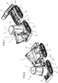
- Figures 1 and 2 show axonometrically a machine moving on chain tracks and equipped with a tipping platform.
- the machine comprises an upper carriage B, or the upper frame, and the undercarriage A, so the lower frame.
- the upper carriage consists of a cabin 10 and a multi-purpose boom 11 which may together be freely rotated around the vertical axis Y.
- the total weight of the multi-purpose work machine is 1 to 40 tons.
- the essential issue in the device according to the invention is that the frame A advantageously comprises a changeable load unit 12, such as an interchangeable platform.
- the frame in frame modules A1 are denoted by reference number 7000 and in the frame module A3 by reference number 700.
- Figure 2 shows the cabin 10 of the machine of Figure 1 and thus the entire work part turned so that the bucket 11e of the boom 11 may drop soil or similar on the platform 12 or generally speaking to a load unit 12.
- the actual work part and thus the cabin 10 with its boom 11 turns at least 360 degrees.
- the cabin 10 is the control cabin for the operator and the control devices of the machine.
- the cabin 10 serves as a base for the remote control equipment, such as cameras. advantageously 3D cameras.. With the 3D cameras, three-dimensional images may be created to remote control the device and to remote control work performances.
- the remote control equipment may be placed in connection with the cabin.
- the machine comprises an upper carriage B, that is, a work part, and below it an undercarriage A, which comprises frame modules A1, A100, A3 which are interconnected and of which the first frame module A1 comprises a bearing ring H for the cabin 10 of the upper carriage B.
- the cabin structure 10 comprises a boom structure rotating with it, to which a tool such as a bucket may be mounted.
- the boom structure comprises one or more booms 11, which are moved by cylinder devices such as hydraulic cylinders.
- a bucket 11e may be detachably hooked up to the boom 11.
- the boom structure is advantageously fitted with a bearing to turn on a joint 11a around the vertical axis Y1 in relation to the cabin 10.
- the vertical axes Y and Y1 are parallel.
- a second frame module A3, a so-called load module, has been pivotally connected to the frame module A1, that is, the cabin module, and between the frame modules A1, A3 there are cylinders (n1, n2) by means of which the frame steering of the machine takes place.
- the first frame module A1 comprises on both its sides chain track sets 200, both of which are supported by their supports 300 and pivoted to rock (arrow S1) around the transverse axis (z) by means of a bearing 900 on the supports 300, whereby the machine moves smoothly in a varying terrain.
- a second frame module A3 has been pivotally connected to the first frame module. It comprises longitudinal frame beams of the frame 700 and chain track sets 200 on both sides of the frame 700, which are pivoted to rock (S1) supported by their supports 300 and bearings 900 on the support 300 around the transverse Z axis.
- Each chain track set 200 comprises inside a loop formed of its chain track 200a a motor M1 moving the chain track 200a. So, the module system comprises four motors M1, one for each chain track set 200.
- the motors M1 are hydraulic or electric motors. Drive energy feed for the hydraulic hoses or electrical wires is as shown in Figure 28 or 13 .
- the frame 700 of the rearmost frame module A3 comprises on top of the frame 700 a load, such as a load unit 12 such as a fixed platform, tipping platform, interchangeable platform or a log frame of a log trailer.
- the load may also be an aggregate, work machine, or another transportable entity which comprises fastening point/points for the hook of the hook device or hooks of the cable device.
- the frame module A1 comprises a bearing ring H to which the cabin 10 is placed in a turning fashion.
- the frame 7000 of the frame module A1 is box-type and casing-like structure which receives the chain track sets 200 on its sides so that the roll. On its top surface, it has the bearing ring H of the cabin 10.
- the chain track sets 200 in question are supported by supports 300 which may be, as in the figures, axles between the frame 7000 and the chain track frame 400, comprising the bearing 900 for the rocking S1. It may be a sliding bearing or a bearing ring consisting of roller elements.
- the support 300 may be a so-called downward beam 800, as in Figures 23, 24, and 25 by means of which the ground clearance of the machine is increased.
- the downward beam 800 is a hollow structure box beam. Through its hollow interior and centred on the bearing ring 900 are the hydraulic lines or hoses ⁇ taken to the motor M1, or electrical wires ⁇ taken to the motor M1 if the motor M1 is an electric motor.
- the motor M1 is a hydraulic motor or an electric motor.
- the frame modules of the multi-purpose work machine are advantageously metal structures.
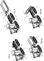
- Figure 3 and 7 show an embodiment of the machine, in which the multi-purpose work machine comprises, as the load unit 12, an interchangeable platform which may be lifted on top of the frame A3 and lowered and left on the ground by a hook device 15. Hydraulic cylinders 16a and 16b turn the frame 17 of the hook device. The hook K of the device couples to a gripping bar on the platform and pulls the platform further onto the module A3..
- Figures 4 and 8 show an embodiment in which an interchangeable platform acting as the load unit 12 is moved to tiltable rails P by a cable device 14 or a chain device.
- the rails P are pivoted at one end thereof to a cable interchangeable device frame J and tiltable by means of hydraulic cylinders 18b and 18b.
- the hydraulic cylinders are pivotally coupled to the frame J of the cable device, and at the other end to the rails P.
- the rails P are pivoted to turn on the bearings T2.
- the cables V may be reeled on wind-up rolls O by using a hydraulic or electric motor M.
- the hook at the other end of the cables V may be coupled to the load unit 12 such as a platform.
- the load such as the platform 12 may be lowered to the ground by using the cylinders to tilt the rails P, which act as a tilt frame.
- the platform 12 moves under gravity from the rails P.
- Figure 8 shows the cable device in a larger scale.
- Figure 5a shows an embodiment where the load unit 12 is a platform that is fixedly on the frame module A3.
- Figure 5b shows the load unit provided with a tipping device 19. The cylinder 19b tilts the platform 12.
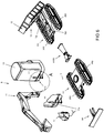
- FIG 6 shows an embodiment of the multi-purpose work machine, in which the lower frame A of the vehicle, that is, the undercarriage, is formed of modules to be interconnected, advantageously of four frame modules A1, A100, A3 and a bulldozer blade module A4.
- FIG. 6 is an illustrative view of the module system of the invention.
- the undercarriage A so the lower frame, is formed of frame modules A1, A3, and A100 which are connected to each other by screw/flange joints D.
- the screws have been brought through perforations in the flanges of the module to be connected to the threaded holes of the second module to be connected.
- the bulldozer blade module A4 is connected as the front-most module.
- an embodiment is also possible in which instead of screw/flange joints welding is used to connect the modules A1, A100, A3 to each other.
- welding instead of screw/flange joints welding is used to connect the modules A1, A100, A3 to each other.
- the machine is of metal.
- the frame module A1 a module which comprises a slewing ring H for the turning bearing of the cabin 10 to rotate the cabin 10 around the vertical axis Y by at least 360 degrees.
- the boom structure 11 of the machine is rotated.
- the boom structure 11 is thus freely rotatable at a joint 11a in relation to the cabin 10 around the axis Y1.
- the pivot axis Y of the cabin and the pivot axis Y1 of the boom structure are parallel.
- a bucket 11e may be detachably hooked up to the boom structure 11.
- the cabin 10 and the structures connected to it are referred to as the upper carriage B, or upper frame.
- the drive motor and hydraulic systems of the device are advantageously associated with the cabin 10 or the vicinity thereof.
- the bulldozer blade module A4 is connected to the frame module A1.
- the rearmost frame module A3 comprises a load unit 12 such as a fixed platform or a tipping device 13 for the load unit 12.
- the tipping device 13 comprises a hydraulic cylinder 13a.
- the frame A is equipped in accordance with the embodiment with a platform, so the module A3 is provided with provisions made for the platform 12, such as holes in the fastenings of the bearing lugs, openings for support lugs, and reinforcements for fastening.
- the module A3 also referred to as a load space module, for the different variations of the load units, such as an interchangeable platform, fixed platform, log trailer platform, hook interchangeable platform, device and cable interchangeable platform device which may detachably and optionally connected to it.
- the frame module A3 is equipped according to the customer's order and needs.
- modules A1, A100, A4 to be connected are chosen and connected to each other according to what the desired multi-purpose work machine is to be like.
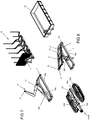
- FIG 7 illustrates a hook device 15 installed on top of the frame module A3.
- the hook device 15 comprises a frame surrounding 15a. To one end thereof, the hydraulic cylinders 16a and 16n have been pivoted, and to the other end the turning frame 17 of the hook device. At their other end, the hydraulic cylinders are connected to the turning frame 17 of the hook device The turning frame 17 is pivoted to turn on bearings T.
- the gripping hook K of the hook device may be brought behind the gripping bar L in the load unit 12, whereby as the turning frame 17 is tilted, the load such as the load unit 12, a log trailer frame in the embodiment, is pulled on top of the module A1.
- Figure 8 shows a second alternative outfit.
- the frame module A3 is equipped with a cable device 14. Its operation is as described on the basis of Figure 4 .
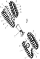
- Figure 9 shows the main modules of the chain track device; load module A3, frame steering module A100, and cabin module A1.
- the motor M1 moves the chain tracks 200a of each chain track set 200 forward and/or backward.
- Each chain track set 200 comprises inside the chain ring a dedicated hydraulic drive motor M1.
- the chain track sets 200 are identical in relation to each other, but mirror images.
- the chain frame 400 is in the middle and supports the chain tracks 200a and its idler wheels 500.
- the chain track sets 200 are pivoted to roll S1.
- Each track system is advantageously pivoted in the middle at the centre line Z to rotate around the horizontal axis Z and supported by the bearing 900 of the support 300. Therefore each chain track set 200 with its chain tracks 200a and frame 400 is rolling.
- a similar arrangement exists on both halves of the frame modules A1, A3, that is, on both sides. This ensures that the machine will move smoothly in a challenging terrain, too.
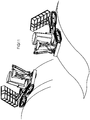
- Figures 10 and 11 illustrated how the chain track device progresses in a terrain of different forms.
- FIG 12 is a side view of the chain track set.
- the chain track set 200 comprises a chain track frame 400 of the chain track 200a inside the chain loop at the transverse centre line Z thereof a support 300, an axle in the embodiment, supported by which then entire chain track set 200 rolls.
- the axle 300 itself does not rotate, but acts as a support axle, and the outer surfaces of the end act as bearing surfaces either as sliding bearing surfaces or support surfaces for the rings of the bearing elements while the frame 400 of the chain track 200 itself rocks supported by them and thus by the bearing 900 they form.
- This causes the chain track set 200 to become rocking, and the rocking takes place around the transverse horizontal axis Z.
- the form of the chain track course is advantageous from the viewpoint of moving in the terrain.
- the chain track 200a comprises a lower horizontal run, the connected run obliquely upward, a curved run at the sheave, the connected upper horizontal run, then at a sheave a curved run, which is connected to an oblique downward run, connected to the lower horizontal run. Due to the oblique track runs, the machine may be made to cross terrain obstacles easily. There is at least one oblique track run at the front of the device, advantageously there are two runs at the front and back of the chain track frame.
- Figure 13 is a cross section A-A of Figure 12 .
- the support 300 of the frame 700 of the chain track set 200 is an axle which in the embodiment comprises on its surface a sliding bearing 900 which makes the rocking (arrow S1) of the chain track set 200 possible.
- the supports 300 may also be a beam 800 running downward to increase the ground clearance of the machine. Such an embodiment of the support 300, so the downward beam 800, is disclosed in the latter embodiments.
- the axle 300 comprises channels ⁇ for leak oil, backward pressure oil, forward pressure oil, braking oil, or the channels ⁇ , such as passages for electrical wires if the motor M1 is an electric motor.
- the oils are led from the end and sides of the axle 300 through pipes/hoses to the motor M1, which is connected to the drive shaft of the end drive wheel at the end of the frame 400 of the chain track set.
- the channel runs at the end of the axle 300 are denoted with the letter ⁇ .
- the motor M1 may be an electric motor or a hydraulic motor.
- One of the end wheels to the chain track is spring-loaded to remove slack from the chain, caused by wear, for example.
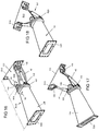
- Figures 14 to 18 show the frame steering module A100 axonometrically.
- Figures 14 to 18 show a so-called frame steering module A100.
- the module half 101 it comprises a joint 102 for the cylinder n1, connected to a moving frame part R10, and a joint 103 at the other end of the cylinder n1, connected to a round frame plate R10 of the frame half 101.
- the frame part R10 is pivoted to turn at the joint 107 in relation to the frame R20.
- the frame part R10 of the half 101 comprises plate-like frame parts R10a and R10b which connect to a connecting flange D10. A placement and moving space is formed for the cylinders n1 and n2 between the plate parts R10a and R10b.
- the cylinder n2 comprises a joint 105 in the module half 101 on its turning frame part R10, and a joint 106 at the other end of the cylinder, connected to the round frame plate R20 of the half on the other side of the centre line X.
- the cylinders n1 and n2 are advantageously hydraulic cylinders. They are thus used to turn the turning frame part R10 of the half 101 and thus the frame halves 101, 104 in relation to each other.
- Arrow S3 Joint axles 108,109 for the rotation S3 pass through the openings in the lugs K1, K2 and the holes in the frame parts R10.
- the lugs K1, K2 are welded to the round plate R20.
- the machine is of metal.
- the frame part R10 with the structures connected to it are adapted to rotate on the joint 108 in relation to the frame part R20.
- the frame part R20 of the half 101 is a round plate, which acts as the base frame part and is, together with the devices connected to it, adapted to rotate by means of a slewing ring bearing 107 in relation to the other frame part 104.
- the turning ring bearing 107 is thus between the halves 101 and 104.
- the half 104 is along its length L1 substantially longer than the half 101 along its length L2.
- the half 101 advantageously connects to the frame module comprising the cabin
- the half 104 advantageously connects to the module comprising a platform or similar.
- the modules comprising the cabin 10 is turned by means of the cylinders n1 and n2 and thus the movable machine.
- the halves 101 and 104 connect to each other at swivel 107 which may comprise bearing elements f10 such as rolls or cone bearing parts or bearing rolls on a ring
- the swivel 107 allows the halves 101 and 104 to rotate (arrow S2) in relation to each other.
- the frame plate R10 of the half 101, with the parts connected thereto, are adapted to turn (arrow S2) in relation to the frame half 104 at the swivel bearing 107.
- the halves 101 and 104 may be locked in relation to each other by the hydraulic cylinder or a brake piston 62 of a brake 60, whereby the frame steering module A100 may be secured at its joints for the duration of loading/working.
- One frame half 101 comprises fastening means D10 and the other frame half 104 comprises fastening means D20.
- the module A100 may be detachably mounted to the different modules of the multi-purpose work machine advantageously so that the half 101 is connected to the cabin and control cabin module, and the conically narrowing half 104 is connected by its flange D20 to the module A3 comprising the load unit.
- the fastening means D10 and D20 are in the embodiments of the figures formed of perforated flanges and screws and nuts, or only of screws and flanges as well as screws holes of the flanges.
- the inventive machine moving on chain tracks is most advantageously a multi-purpose work machine moving on chain tracks.
- the modules may be connected to each other by welding.
- the machine is of metal.
- Figure 19 shows a cross-section B-B of Figure 15 ,
- the frame part R20 rotates (arrow S) with the connected frame parts R10 and cylinders n1 and n2 in relation to the other frame half 104, enabled by the turning ring bearing 107.
- This way, the load being drawn may rotate in relation to the towing part in the terrain.
- the machine can be made to move in a difficult terrain, too.
- the machine is well suited to a multi-purpose machine moved on chain tracks.
- the frame steering module A100 may be mounted to the frame modules A1, A3 directly with a welded joint, instead of the detachable flange joint.
- the round base frame part R20 of the half 101 is fitted with bearings to rotate with the structural parts R10, n1, n2 on the ring bearing 107 in relation to the frame half 104.
- the frame halves 101, 104 may be locked in the figure to not rotate in relation to each other by a locking device, that is, brake 60, which as shown in the figure is a cylinder comprising a locking/braking piston 62.
- brake 60 which as shown in the figure is a cylinder comprising a locking/braking piston 62.
- the frame steering module A100 may be locked/secured for the duration of loading by having the cylinders n1 and n2 locked and by locking the brake 60 by bringing oil pressure to the piston 62 of the brake 60 through the channel 61, which locks the ring bearing 107.
- the piston 62 is in the locking pressed against the surfaces of the frame half 101.
- the brake 60 is fixed to the frame half 104 by its cylinder frame.
- the frame half 104 widens conically towards its end comprising the connecting flange D20.
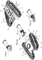
- Figure 20 shows axonometrically the first frame module A1, frame steering module A100, and the rearmost frame module A3 comprising a load space 12.
- Figures 21 and 22 show different rotation positions of the frame steering module A100.
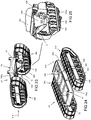
- Figures 23 and 24 show the chain track set 200 and the lower carriage A in an embodiment in which there is a support 300 of the chain track 200, running downward from the horizontal frame beam 700a of the machine frame 700, in the embodiment a downward beam 800, to increase the ground clearance of the machine.
- a support 300 of the chain track 200 running downward from the horizontal frame beam 700a of the machine frame 700, in the embodiment a downward beam 800, to increase the ground clearance of the machine.
- electrical wires or hydraulic lines or hydraulic hoses or hydraulic pipes have been brought for the motor M1 moving the chain track.
- the motor M1 is thus a hydraulic motor or an electric motor.
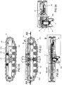
- Figure 25 shows the circled area V1 of Figure 23 .
- the downward beam 800 comprises a bearing 900 for the roll (arrow S1) of the chain track set 200.
- Figure 26 the chain track set 200 is shown from the direction of the arrow K20 of Figure 23 , and in Figure 27 from the direction of the arrow K10 of Figure 23 .
- Figure 28 is a cross section AA-AA of Figure 27 .
- the downward beam 800 comprises at its end a bearing 900, one bearing half t1 of which connects to the downward beam 800 to its lower side end, and the other bearing half t2 is connected to the frame 400 of the chain track set 200, and the bearing 900 in question comprises on a circle ring between the bearing halves t1 and t2 the roller elements f of the bearing 900.
- Figure 29 shows the area B of Figure 28 .
- a so-called through-bushing 65 provided with play, advantageously a sliding fit, to which the electric wires or hydraulic hoses or pipes to the motor M1 are received. They exit the bushing 65 and are brought in to the bushing 65. They connect to the motor M1, which is an electric or hydraulic motor and drives the sprocket wheel 68 on its axle. At the same time, it acts and the sheave of the chain track ring 200a and connects to the spoke parts of the chain track ring 200a, moving the chain track 200a in the clockwise or anticlockwise direction and thus the machine forwards or backwards.
- the chain track 200a is directed as a loop through idler wheels 500, which are fastened to the chain track frame 400.
- One of the sheaves of the loop is the sprocket wheel 68 of the chain track 200a, driven by the motor M1, and the other one is a spring-loaded sheave.
- an embodiment of the invention is also possible in which only the frame module A1 is provided by the motor M1 in the chain track sets 200 and in which the frame module A3 connected to it in a frame steered manner comprises the rocking chain track sets 200, only, without the drive motor M1.
- the structure A3 of the frame module A3 in question is the same as the frame module A3 equipped with the motor M1 and shown in the drawings.
Landscapes
- Engineering & Computer Science (AREA)
- Chemical & Material Sciences (AREA)
- Combustion & Propulsion (AREA)
- Transportation (AREA)
- Mechanical Engineering (AREA)
- Mining & Mineral Resources (AREA)
- Civil Engineering (AREA)
- General Engineering & Computer Science (AREA)
- Structural Engineering (AREA)
- Body Structure For Vehicles (AREA)
Priority Applications (1)
| Application Number | Priority Date | Filing Date | Title |
|---|---|---|---|
| PL18171819T PL3401447T3 (pl) | 2017-05-12 | 2018-05-11 | Maszyna przemieszczająca się z wykorzystaniem gąsienic łańcuchowych |
Applications Claiming Priority (1)
| Application Number | Priority Date | Filing Date | Title |
|---|---|---|---|
| FI20174131 | 2017-05-12 |
Publications (2)
| Publication Number | Publication Date |
|---|---|
| EP3401447A1 EP3401447A1 (en) | 2018-11-14 |
| EP3401447B1 true EP3401447B1 (en) | 2021-01-20 |
Family
ID=62791484
Family Applications (1)
| Application Number | Title | Priority Date | Filing Date |
|---|---|---|---|
| EP18171819.8A Active EP3401447B1 (en) | 2017-05-12 | 2018-05-11 | Machine moving with chain tracks |
Country Status (2)
| Country | Link |
|---|---|
| EP (1) | EP3401447B1 (pl) |
| PL (1) | PL3401447T3 (pl) |
Families Citing this family (10)
| Publication number | Priority date | Publication date | Assignee | Title |
|---|---|---|---|---|
| CN109305238B (zh) * | 2018-12-03 | 2023-09-29 | 河北工业大学 | 一种被动自适应的履带机器人移动平台 |
| CN109733504B (zh) * | 2018-12-27 | 2021-02-26 | 浙江省交通规划设计研究院有限公司 | 轮腿式无人飞行检测机器人 |
| CN114174596B (zh) * | 2019-09-18 | 2024-03-08 | 住友重机械工业株式会社 | 挖土机 |
| CN111017053B (zh) * | 2019-11-15 | 2024-04-02 | 上海江南长兴造船有限责任公司 | 一种爬壁式机器人底座 |
| CN113415117B (zh) * | 2021-05-14 | 2022-11-22 | 四川农业大学 | 一种小型底盘调平装置 |
| CN113479023B (zh) * | 2021-07-30 | 2023-08-04 | 广东永强奥林宝国际消防汽车有限公司 | 一种双模块履带式水路两栖消防车 |
| CN113969598B (zh) | 2021-12-02 | 2025-11-11 | 江苏徐工工程机械研究院有限公司 | 模块化挖掘机 |
| CN114348919A (zh) * | 2022-03-17 | 2022-04-15 | 新乡职业技术学院 | 一种智能仓储用叉车固定底座 |
| CN116039787B (zh) * | 2022-12-16 | 2025-07-11 | 冀凯河北机电科技有限公司 | 一种多功能履带运输车 |
| CN121519566A (zh) * | 2025-12-16 | 2026-02-13 | 山东德瑞矿山机械有限公司 | 折叠式侧卸井下无轨铲运机卸料机构 |
Family Cites Families (5)
| Publication number | Priority date | Publication date | Assignee | Title |
|---|---|---|---|---|
| DE2434556A1 (de) * | 1974-07-18 | 1976-03-04 | Krone Bernhard Gmbh Maschf | Geraetetraeger |
| CA2157265C (en) * | 1995-08-30 | 1999-02-02 | Donald Gauvin | Articulated vehicle |
| US7617881B2 (en) * | 2004-11-29 | 2009-11-17 | Deere & Company | Articulated crawler tractor |
| SE533130C2 (sv) * | 2007-02-05 | 2010-07-06 | Rolf Volungholen | Fordon för avverkning av skog och/eller transport av virkesbitar |
| SE537571C2 (sv) * | 2013-10-10 | 2015-06-23 | Komatsu Forest Ab | Anordning för att anpassa marktrycket hos ett terränggåendemotorfordon och ett terränggående motorfordon utrustad med en sådan anordning |
-
2018
- 2018-05-11 PL PL18171819T patent/PL3401447T3/pl unknown
- 2018-05-11 EP EP18171819.8A patent/EP3401447B1/en active Active
Non-Patent Citations (1)
| Title |
|---|
| None * |
Also Published As
| Publication number | Publication date |
|---|---|
| PL3401447T3 (pl) | 2021-08-02 |
| EP3401447A1 (en) | 2018-11-14 |
Similar Documents
| Publication | Publication Date | Title |
|---|---|---|
| EP3401447A1 (en) | Machine moving with chain tracks | |
| US4253256A (en) | Self-loading dualistic earth excavator with connecting telescopic conveying and dualistic distribution means | |
| CA2015719C (en) | Continuously operating open-cast mining device with a cylindrical breaking tool | |
| EP3155183B1 (en) | Excavator | |
| JP6688796B2 (ja) | 重量のある作業機を傾斜を有するベースにおいて移送する方法および移送機構 | |
| CN105569105A (zh) | 工作机的底盘 | |
| US10822209B1 (en) | Lift attachment apparatus | |
| US3500563A (en) | Wheel-type top loading machine and method | |
| US20160280118A1 (en) | Construction Machine Transport | |
| RU2045465C1 (ru) | Универсальный трактор | |
| US11131111B2 (en) | Mast coupling assembly for a mobile drilling machine | |
| US6336558B1 (en) | Tractor unit and wheeled trailer combination | |
| CN204371333U (zh) | 一种全液压单钻臂钻装机组 | |
| EP3401446B1 (en) | Multi-purpose work machine | |
| FI12141U1 (fi) | Telaketjuilla liikkuva kone | |
| US11479453B1 (en) | Lift attachment apparatus | |
| JP3689165B2 (ja) | 切り上がり掘削用の資機材搬送構造 | |
| US12404152B1 (en) | Lift attachment apparatus | |
| JPH11291960A (ja) | クローラ式産業車両 | |
| RU2752043C2 (ru) | Мобильный полноповоротный комплекс | |
| JP4199737B2 (ja) | 搬送手段を備えたバックホー | |
| JP2534550B2 (ja) | 道床の交換方法 | |
| JP3136769U (ja) | 自走式散水装置 | |
| RU2759398C2 (ru) | Мобильный полноповоротный комплекс | |
| KR101193873B1 (ko) | 중장비 부품 이송 장치 |
Legal Events
| Date | Code | Title | Description |
|---|---|---|---|
| PUAI | Public reference made under article 153(3) epc to a published international application that has entered the european phase |
Free format text: ORIGINAL CODE: 0009012 |
|
| STAA | Information on the status of an ep patent application or granted ep patent |
Free format text: STATUS: THE APPLICATION HAS BEEN PUBLISHED |
|
| AK | Designated contracting states |
Kind code of ref document: A1 Designated state(s): AL AT BE BG CH CY CZ DE DK EE ES FI FR GB GR HR HU IE IS IT LI LT LU LV MC MK MT NL NO PL PT RO RS SE SI SK SM TR |
|
| AX | Request for extension of the european patent |
Extension state: BA ME |
|
| STAA | Information on the status of an ep patent application or granted ep patent |
Free format text: STATUS: REQUEST FOR EXAMINATION WAS MADE |
|
| 17P | Request for examination filed |
Effective date: 20190513 |
|
| RBV | Designated contracting states (corrected) |
Designated state(s): AL AT BE BG CH CY CZ DE DK EE ES FI FR GB GR HR HU IE IS IT LI LT LU LV MC MK MT NL NO PL PT RO RS SE SI SK SM TR |
|
| GRAP | Despatch of communication of intention to grant a patent |
Free format text: ORIGINAL CODE: EPIDOSNIGR1 |
|
| STAA | Information on the status of an ep patent application or granted ep patent |
Free format text: STATUS: GRANT OF PATENT IS INTENDED |
|
| INTG | Intention to grant announced |
Effective date: 20200817 |
|
| GRAS | Grant fee paid |
Free format text: ORIGINAL CODE: EPIDOSNIGR3 |
|
| GRAA | (expected) grant |
Free format text: ORIGINAL CODE: 0009210 |
|
| STAA | Information on the status of an ep patent application or granted ep patent |
Free format text: STATUS: THE PATENT HAS BEEN GRANTED |
|
| AK | Designated contracting states |
Kind code of ref document: B1 Designated state(s): AL AT BE BG CH CY CZ DE DK EE ES FI FR GB GR HR HU IE IS IT LI LT LU LV MC MK MT NL NO PL PT RO RS SE SI SK SM TR |
|
| REG | Reference to a national code |
Ref country code: GB Ref legal event code: FG4D |
|
| REG | Reference to a national code |
Ref country code: CH Ref legal event code: EP |
|
| REG | Reference to a national code |
Ref country code: DE Ref legal event code: R096 Ref document number: 602018011961 Country of ref document: DE |
|
| REG | Reference to a national code |
Ref country code: AT Ref legal event code: REF Ref document number: 1356513 Country of ref document: AT Kind code of ref document: T Effective date: 20210215 |
|
| REG | Reference to a national code |
Ref country code: IE Ref legal event code: FG4D |
|
| REG | Reference to a national code |
Ref country code: FI Ref legal event code: FGE |
|
| REG | Reference to a national code |
Ref country code: CH Ref legal event code: NV Representative=s name: VALIPAT S.A. C/O BOVARD SA NEUCHATEL, CH |
|
| REG | Reference to a national code |
Ref country code: SE Ref legal event code: TRGR |
|
| REG | Reference to a national code |
Ref country code: NL Ref legal event code: MP Effective date: 20210120 |
|
| REG | Reference to a national code |
Ref country code: LT Ref legal event code: MG9D |
|
| REG | Reference to a national code |
Ref country code: AT Ref legal event code: MK05 Ref document number: 1356513 Country of ref document: AT Kind code of ref document: T Effective date: 20210120 Ref country code: EE Ref legal event code: FG4A Ref document number: E020892 Country of ref document: EE Effective date: 20210506 |
|
| PG25 | Lapsed in a contracting state [announced via postgrant information from national office to epo] |
Ref country code: LT Free format text: LAPSE BECAUSE OF FAILURE TO SUBMIT A TRANSLATION OF THE DESCRIPTION OR TO PAY THE FEE WITHIN THE PRESCRIBED TIME-LIMIT Effective date: 20210120 Ref country code: PT Free format text: LAPSE BECAUSE OF FAILURE TO SUBMIT A TRANSLATION OF THE DESCRIPTION OR TO PAY THE FEE WITHIN THE PRESCRIBED TIME-LIMIT Effective date: 20210520 Ref country code: NO Free format text: LAPSE BECAUSE OF FAILURE TO SUBMIT A TRANSLATION OF THE DESCRIPTION OR TO PAY THE FEE WITHIN THE PRESCRIBED TIME-LIMIT Effective date: 20210420 Ref country code: GR Free format text: LAPSE BECAUSE OF FAILURE TO SUBMIT A TRANSLATION OF THE DESCRIPTION OR TO PAY THE FEE WITHIN THE PRESCRIBED TIME-LIMIT Effective date: 20210421 Ref country code: HR Free format text: LAPSE BECAUSE OF FAILURE TO SUBMIT A TRANSLATION OF THE DESCRIPTION OR TO PAY THE FEE WITHIN THE PRESCRIBED TIME-LIMIT Effective date: 20210120 Ref country code: BG Free format text: LAPSE BECAUSE OF FAILURE TO SUBMIT A TRANSLATION OF THE DESCRIPTION OR TO PAY THE FEE WITHIN THE PRESCRIBED TIME-LIMIT Effective date: 20210420 |
|
| PG25 | Lapsed in a contracting state [announced via postgrant information from national office to epo] |
Ref country code: AT Free format text: LAPSE BECAUSE OF FAILURE TO SUBMIT A TRANSLATION OF THE DESCRIPTION OR TO PAY THE FEE WITHIN THE PRESCRIBED TIME-LIMIT Effective date: 20210120 Ref country code: LV Free format text: LAPSE BECAUSE OF FAILURE TO SUBMIT A TRANSLATION OF THE DESCRIPTION OR TO PAY THE FEE WITHIN THE PRESCRIBED TIME-LIMIT Effective date: 20210120 Ref country code: RS Free format text: LAPSE BECAUSE OF FAILURE TO SUBMIT A TRANSLATION OF THE DESCRIPTION OR TO PAY THE FEE WITHIN THE PRESCRIBED TIME-LIMIT Effective date: 20210120 |
|
| PG25 | Lapsed in a contracting state [announced via postgrant information from national office to epo] |
Ref country code: IS Free format text: LAPSE BECAUSE OF FAILURE TO SUBMIT A TRANSLATION OF THE DESCRIPTION OR TO PAY THE FEE WITHIN THE PRESCRIBED TIME-LIMIT Effective date: 20210520 |
|
| REG | Reference to a national code |
Ref country code: DE Ref legal event code: R097 Ref document number: 602018011961 Country of ref document: DE |
|
| PG25 | Lapsed in a contracting state [announced via postgrant information from national office to epo] |
Ref country code: SM Free format text: LAPSE BECAUSE OF FAILURE TO SUBMIT A TRANSLATION OF THE DESCRIPTION OR TO PAY THE FEE WITHIN THE PRESCRIBED TIME-LIMIT Effective date: 20210120 |
|
| PLBE | No opposition filed within time limit |
Free format text: ORIGINAL CODE: 0009261 |
|
| STAA | Information on the status of an ep patent application or granted ep patent |
Free format text: STATUS: NO OPPOSITION FILED WITHIN TIME LIMIT |
|
| PG25 | Lapsed in a contracting state [announced via postgrant information from national office to epo] |
Ref country code: RO Free format text: LAPSE BECAUSE OF FAILURE TO SUBMIT A TRANSLATION OF THE DESCRIPTION OR TO PAY THE FEE WITHIN THE PRESCRIBED TIME-LIMIT Effective date: 20210120 Ref country code: DK Free format text: LAPSE BECAUSE OF FAILURE TO SUBMIT A TRANSLATION OF THE DESCRIPTION OR TO PAY THE FEE WITHIN THE PRESCRIBED TIME-LIMIT Effective date: 20210120 Ref country code: SK Free format text: LAPSE BECAUSE OF FAILURE TO SUBMIT A TRANSLATION OF THE DESCRIPTION OR TO PAY THE FEE WITHIN THE PRESCRIBED TIME-LIMIT Effective date: 20210120 |
|
| 26N | No opposition filed |
Effective date: 20211021 |
|
| PG25 | Lapsed in a contracting state [announced via postgrant information from national office to epo] |
Ref country code: ES Free format text: LAPSE BECAUSE OF FAILURE TO SUBMIT A TRANSLATION OF THE DESCRIPTION OR TO PAY THE FEE WITHIN THE PRESCRIBED TIME-LIMIT Effective date: 20210120 Ref country code: AL Free format text: LAPSE BECAUSE OF FAILURE TO SUBMIT A TRANSLATION OF THE DESCRIPTION OR TO PAY THE FEE WITHIN THE PRESCRIBED TIME-LIMIT Effective date: 20210120 Ref country code: LU Free format text: LAPSE BECAUSE OF NON-PAYMENT OF DUE FEES Effective date: 20210511 Ref country code: MC Free format text: LAPSE BECAUSE OF FAILURE TO SUBMIT A TRANSLATION OF THE DESCRIPTION OR TO PAY THE FEE WITHIN THE PRESCRIBED TIME-LIMIT Effective date: 20210120 |
|
| REG | Reference to a national code |
Ref country code: BE Ref legal event code: MM Effective date: 20210531 |
|
| PG25 | Lapsed in a contracting state [announced via postgrant information from national office to epo] |
Ref country code: SI Free format text: LAPSE BECAUSE OF FAILURE TO SUBMIT A TRANSLATION OF THE DESCRIPTION OR TO PAY THE FEE WITHIN THE PRESCRIBED TIME-LIMIT Effective date: 20210120 |
|
| PG25 | Lapsed in a contracting state [announced via postgrant information from national office to epo] |
Ref country code: IE Free format text: LAPSE BECAUSE OF NON-PAYMENT OF DUE FEES Effective date: 20210511 |
|
| PG25 | Lapsed in a contracting state [announced via postgrant information from national office to epo] |
Ref country code: IS Free format text: LAPSE BECAUSE OF FAILURE TO SUBMIT A TRANSLATION OF THE DESCRIPTION OR TO PAY THE FEE WITHIN THE PRESCRIBED TIME-LIMIT Effective date: 20210520 |
|
| PG25 | Lapsed in a contracting state [announced via postgrant information from national office to epo] |
Ref country code: BE Free format text: LAPSE BECAUSE OF NON-PAYMENT OF DUE FEES Effective date: 20210531 |
|
| PG25 | Lapsed in a contracting state [announced via postgrant information from national office to epo] |
Ref country code: NL Free format text: LAPSE BECAUSE OF NON-PAYMENT OF DUE FEES Effective date: 20210120 Ref country code: CY Free format text: LAPSE BECAUSE OF FAILURE TO SUBMIT A TRANSLATION OF THE DESCRIPTION OR TO PAY THE FEE WITHIN THE PRESCRIBED TIME-LIMIT Effective date: 20210120 |
|
| PG25 | Lapsed in a contracting state [announced via postgrant information from national office to epo] |
Ref country code: HU Free format text: LAPSE BECAUSE OF FAILURE TO SUBMIT A TRANSLATION OF THE DESCRIPTION OR TO PAY THE FEE WITHIN THE PRESCRIBED TIME-LIMIT; INVALID AB INITIO Effective date: 20180511 |
|
| PG25 | Lapsed in a contracting state [announced via postgrant information from national office to epo] |
Ref country code: MK Free format text: LAPSE BECAUSE OF FAILURE TO SUBMIT A TRANSLATION OF THE DESCRIPTION OR TO PAY THE FEE WITHIN THE PRESCRIBED TIME-LIMIT Effective date: 20210120 |
|
| PG25 | Lapsed in a contracting state [announced via postgrant information from national office to epo] |
Ref country code: TR Free format text: LAPSE BECAUSE OF FAILURE TO SUBMIT A TRANSLATION OF THE DESCRIPTION OR TO PAY THE FEE WITHIN THE PRESCRIBED TIME-LIMIT Effective date: 20210120 |
|
| PGFP | Annual fee paid to national office [announced via postgrant information from national office to epo] |
Ref country code: CZ Payment date: 20240502 Year of fee payment: 7 |
|
| PG25 | Lapsed in a contracting state [announced via postgrant information from national office to epo] |
Ref country code: MT Free format text: LAPSE BECAUSE OF FAILURE TO SUBMIT A TRANSLATION OF THE DESCRIPTION OR TO PAY THE FEE WITHIN THE PRESCRIBED TIME-LIMIT Effective date: 20210120 |
|
| REG | Reference to a national code |
Ref country code: DE Ref legal event code: R082 Ref document number: 602018011961 Country of ref document: DE Representative=s name: WUESTHOFF & WUESTHOFF PATENTANWAELTE UND RECHT, DE |
|
| PG25 | Lapsed in a contracting state [announced via postgrant information from national office to epo] |
Ref country code: CZ Free format text: LAPSE BECAUSE OF NON-PAYMENT OF DUE FEES Effective date: 20250511 |
|
| REG | Reference to a national code |
Ref country code: CH Ref legal event code: U11 Free format text: ST27 STATUS EVENT CODE: U-0-0-U10-U11 (AS PROVIDED BY THE NATIONAL OFFICE) Effective date: 20260601 |
|
| PGFP | Annual fee paid to national office [announced via postgrant information from national office to epo] |
Ref country code: GB Payment date: 20260527 Year of fee payment: 9 Ref country code: PL Payment date: 20260510 Year of fee payment: 9 |
|
| PGFP | Annual fee paid to national office [announced via postgrant information from national office to epo] |
Ref country code: IT Payment date: 20260527 Year of fee payment: 9 |
|
| PGFP | Annual fee paid to national office [announced via postgrant information from national office to epo] |
Ref country code: DE Payment date: 20260528 Year of fee payment: 9 |
|
| PGFP | Annual fee paid to national office [announced via postgrant information from national office to epo] |
Ref country code: SE Payment date: 20260527 Year of fee payment: 9 Ref country code: FI Payment date: 20260527 Year of fee payment: 9 |
|
| PGFP | Annual fee paid to national office [announced via postgrant information from national office to epo] |
Ref country code: CH Payment date: 20260601 Year of fee payment: 9 |
|
| PGFP | Annual fee paid to national office [announced via postgrant information from national office to epo] |
Ref country code: EE Payment date: 20260528 Year of fee payment: 9 |
|
| PGFP | Annual fee paid to national office [announced via postgrant information from national office to epo] |
Ref country code: FR Payment date: 20260528 Year of fee payment: 9 |