EP3401446B1 - Mehrzweckarbeitsmaschine - Google Patents
Mehrzweckarbeitsmaschine Download PDFInfo
- Publication number
- EP3401446B1 EP3401446B1 EP18171813.1A EP18171813A EP3401446B1 EP 3401446 B1 EP3401446 B1 EP 3401446B1 EP 18171813 A EP18171813 A EP 18171813A EP 3401446 B1 EP3401446 B1 EP 3401446B1
- Authority
- EP
- European Patent Office
- Prior art keywords
- frame
- work machine
- module
- purpose work
- undercarriage
- Prior art date
- Legal status (The legal status is an assumption and is not a legal conclusion. Google has not performed a legal analysis and makes no representation as to the accuracy of the status listed.)
- Active
Links
Images


Classifications
-
- E—FIXED CONSTRUCTIONS
- E02—HYDRAULIC ENGINEERING; FOUNDATIONS; SOIL SHIFTING
- E02F—DREDGING; SOIL-SHIFTING
- E02F7/00—Equipment for conveying or separating excavated material
- E02F7/04—Loading devices mounted on a dredger or an excavator hopper dredgers, also equipment for unloading the hopper
-
- B—PERFORMING OPERATIONS; TRANSPORTING
- B62—LAND VEHICLES FOR TRAVELLING OTHERWISE THAN ON RAILS
- B62D—MOTOR VEHICLES; TRAILERS
- B62D33/00—Superstructures for load-carrying vehicles
-
- E—FIXED CONSTRUCTIONS
- E02—HYDRAULIC ENGINEERING; FOUNDATIONS; SOIL SHIFTING
- E02F—DREDGING; SOIL-SHIFTING
- E02F3/00—Dredgers; Soil-shifting machines
- E02F3/04—Dredgers; Soil-shifting machines mechanically-driven
- E02F3/96—Dredgers; Soil-shifting machines mechanically-driven with arrangements for alternate or simultaneous use of different digging elements
- E02F3/963—Arrangements on backhoes for alternate use of different tools
- E02F3/964—Arrangements on backhoes for alternate use of different tools of several tools mounted on one machine
-
- E—FIXED CONSTRUCTIONS
- E02—HYDRAULIC ENGINEERING; FOUNDATIONS; SOIL SHIFTING
- E02F—DREDGING; SOIL-SHIFTING
- E02F9/00—Component parts of dredgers or soil-shifting machines, not restricted to one of the kinds covered by groups E02F3/00 - E02F7/00
- E02F9/08—Superstructures; Supports for superstructures
- E02F9/0808—Improving mounting or assembling, e.g. frame elements, disposition of all the components on the superstructures
-
- E—FIXED CONSTRUCTIONS
- E02—HYDRAULIC ENGINEERING; FOUNDATIONS; SOIL SHIFTING
- E02F—DREDGING; SOIL-SHIFTING
- E02F9/00—Component parts of dredgers or soil-shifting machines, not restricted to one of the kinds covered by groups E02F3/00 - E02F7/00
- E02F9/08—Superstructures; Supports for superstructures
- E02F9/0841—Articulated frame, i.e. having at least one pivot point between two travelling gear units
Definitions
- the invention relates to a multi-purpose work machine.
- Prior art work machine solutions do not allow an advantageous total solution for work carried out by, for example, a combination of an excavator-loader and a transporter.
- a separate excavator and a separate transfer vehicle or a wheel loader for the material have been used.
- Document DE 297 08 637 U1 discloses a combination work vehicle with a swivelling driver's cabin.
- Document WO 2015/053689 A1 discloses an arrangement for a terrain-going motor vehicle.
- a new total solution according to the invention is put forth for a multi-purpose work machine that on its own carries out, for example, digging work, lifting of cleared material onto a platform and transporting it away from a site.
- a solution is disclosed, by means of which also other work may be performed, including personnel hoist work, scattering of material onto an underlay, and bulldozer clearing of soil.
- the multi-purpose work machine is terrain-capable and is able to move on challenging terrain, too.
- the multi-purpose work machine may be used to carry tools that are needed in levelling operations, excavating work, and snow work.
- the multi-purpose work machine is fast enough to perform transports.
- the multi-purpose work machine according to the invention is thanks to its extensive equipping potential suitable for enhancing the completion of the diverse tasks that municipalities, parishes, construction companies, contracting companies, machine rental companies, agriculture and forestry, the construction, repair, and clearing of power lines, armed forces, recycling material processing, industry and service providers of various kinds are faced with.
- the multi-purpose work machine digs, loads, lifts and transports, and as a result of its diverse equipping potential is able to carry out different tasks at a job site in an efficient manner. It is suited to transporting work materials both at a site and for short-distance transports.
- the platform is provided with a tipping device, making the multi-purpose work machine suitable for unloading sand, granular material and materials in general by tipping from the platform.
- the device may on its own carry out excavator work, loading work, personnel hoist work as well as moving to and from a site.
- a multi-purpose boom may be equipped modularly and transformably by a personnel hoist, bucket, or grab so that different tasks may be performed with one and the same machine.
- the multi-purpose work machine may be equipped with different kinds of interchangeable platform systems.
- the invention is additionally well suited to landscaping, taking care of grounds of properties, and to construction sites.
- the working efficiency of a machinery contractor is enhanced when performing many different tasks can be accomplished with one machine without the need for dedicated machines.
- the multi-purpose work machine according to our invention is usable throughout the year.
- the multi-purpose work machine is available in many size categories from 2 to 90 tons.
- the axles solutions are selected on the basis of the required carrying capacity and the surface pressure requirements of the environment.
- the axles are both at the front and back of the frame.
- the wheels of the front axles or rear axles turn, or optionally both turn.
- An embodiment of the invention comprises a solution in which the machine is optionally controlled by remote control.
- the machine comprises a camera/cameras for remote control, by means of which an image is obtained from the machine just like from its cabin.
- remote control devices for the remote control of the motor and tools, such as a boom, bucket and similar tools.
- the control device may be remotely located and separate from the machine itself.
- the multi-purpose work machine according to the invention is a modular structure, which has a frame part and on it axles both at the front and back of the frame.
- the wheels of the axles turn both at the front and back of the frame.
- the modular structure ensures that as the frame is a standard structure it is provided with provisions for platforms and tools of various kinds.
- the multi-purpose work machine comprises, at one end of the frame, a work part which rotates freely and advantageously at least 360 degrees unrestrictedly around its vertical axis Y, the part comprising a boom and a cabin from which the machine is controlled and steered.
- the boom turns freely with the cabin and advantageously at least 360 degrees around the vertical axis Y.
- the structural solution of the work part is excavator-like.
- the boom may be equipped with a bucket or man cage or a separate gripping part, or grab, or crusher jaws or chipping device, that is, different kinds of tools.
- the boom is hence a multi-purpose boom enabling different kinds of work performances.
- the different tools may be mounted on it detachably at the end of the boom advantageously with quick clamping.
- a reference may also be made to a boom structure, comprising at least one boom, which boom structure or boom is moved with actuators such as hydraulic cylinders.
- the platform and interchangeable platform in an embodiment comprises a chain conveyor at the bottom of the platform, used to unload stabilizing agent, for example, at an earth-moving site.
- the multi-purpose work machine is frame or wheel-steered.
- the multi-purpose work machine may be supported with a bulldozer blade and cylinder to the ground and/or with side support legs to the ground.
- the frame steer module disclosed in the invention is used, the joint between the frame may be locked for the duration of loading.
- An embodiment of the invention comprises as auxiliary equipment a solution in which the machine is controlled by remote control.
- the machine comprises a camera/cameras for remote control, by means of which an image is obtained from the machine just like from its cabin.
- remote control devices for the remote control of the motor and tools such as a boom, bucket and similar tools.
- the frame in a preferred embodiment of the invention comprises one or more module parts, advantageously a plurality of module parts, and advantageously three frame portions, that is, frame modules.
- the modules are provided with provisions of different kinds for different connection alternatives. So, it is enough to simply know the auxiliary device to be attached, such as a platform, and its installation is ready to be immediately performed. There is no need for machining, welding or any similar arrangements. Cost savings result from storage costs, for example.
- the steering of the multi-purpose work machine may, as mentioned, be frame steering performed by cylinders. If the wheels of the axles are steering and turning, frame steering will not be used.
- the multi-purpose work machine comprises a detachable bulldozer blade and support legs on the sides.
- the bulldozer blade may be pressed to the ground by cylinders whereby the machine may be supported to the ground during operation of the boom not only by the bulldozer blade but also by the support legs.
- the multi-purpose work machine is optionally provided by an additional power source which is placed on top of the frame immediately behind the platform and work part.
- the additional power source may be a diesel motor or, generally speaking, an internal combustion engine, and it may comprise a pump device to create hydraulic pressure for the hub motors on the rear axles.
- the arrangement may also be entirely electric and battery-based, or a combination of an internal combustion engine and an electric motor, or a combination of a hydraulic system and electric system.
- the additional power source bring the additional energy needed to the work device outfit.
- the multi-purpose work machine according to the invention is characterized by what is disclosed in the claims.
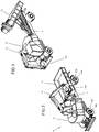
- Figure 1 shows axonometrically a multi-purpose work machine equipped with a tipping platform.
- the machine comprises an upper carriage B, or the upper frame, and the undercarriage A, so the lower frame.
- the upper carriage consists of a cabin 10, or the device cabin, and a multi-purpose boom 11 which may be rotated together 360 degrees around the vertical axis Y.
- the undercarriage A comprises 2 to 6 axles 50a, 51a.... and on them wheels 50b, 51b till
- the total weight of the multi-purpose work machine is 1 to 90 tons and the maximum speed is the speed allowed for a traffic tractor.
- the essential issue in the device according to the invention is that the frame A comprises a changeable load unit 12, such as an interchangeable platform.
- the drive may be on the front axle 50a or the rear axle 51a, or both.
- the machine steering in the embodiment is such that the front wheels 50b turn. An embodiment is also possible where the front wheels 50b and rear wheels 51b turn.
- the cabin 10 serves as a base for the remote controller equipment, such as a camera or cameras.
- the camera is advantageously a 3D camera producing three-dimensional images.
- the machine may steered and the tools, such as the boom, be controlled and used in a remote-controlled fashion.
- the cabin 10 is a compartment comprising room for the operator and the steering means of the machine.
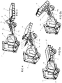
- Figure 2 shows the cabin 10 of the machine of Figure 1 and thus the entire work part turned so that the bucket 11e of the boom 11 may drop soil or similar on the platform 12 or generally speaking to a load unit 12.
- the actual work part B that is, the upper carriage and so the cabin 10 with its boom 11 turns at least 360 degrees.
- FIG 3 shows an embodiment of the multi-purpose work machine, in which the multi-purpose work machine comprises, as the load unit 12, an interchangeable platform which may be lifted on top of the frame A and lowered and left on the ground by a cable device 15. Hydraulic cylinders 16a and 16b turn the frame 17 of the hook device. The hook K of the device couples to a gripping bar on the platform and pulls the platform onto the frame A.
- Figure 4 shows an embodiment in which an interchangeable platform acting as the load unit 12 is moved to tiltable rails P by a cable device 14 or a chain device.
- the rails P are pivoted by bearings T2 at one end thereof to a cable device frame J and tiltable by means of hydraulic cylinders 18a and 18b.
- the hydraulic cylinders are pivotally coupled at one end thereof to the frame J of the cable device, and at the other end to the rails P.
- the cables V may be reeled on wind-up rolls O by using a hydraulic or electric motor M which rotates the wind-up rolls O.
- the hook at the other end of the cables V may be coupled to the load, such as the load unit 12 such as an interchangeable platform to its fixing points such as lugs having holes in them.
- the platform 12 may be lowered to the ground by using the cylinders to tilt the rails P, which act as a tilt frame.
- the platform 12 moves under gravity from the rails P to the ground.
- Figure 8 shows the equipment in a larger
- Figure 5 shows an embodiment where the load unit 12 is a platform that is fixedly on the frame A.
- Figure 5b shows an ordinary tipping platform 12, The platform 12 is tilted by means of cylinders 13a and 13b.
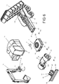
- FIG 6 shows an embodiment of the multi-purpose work machine, in which the lower frame A of the vehicle, that is, the undercarriage, is formed of modules to be interconnected, advantageously of three frame modules A1, A2, A3 to be interconnected, and a bulldozer blade module A4.
- FIG. 6 is an illustrative view of the module system of the invention.
- the undercarriage A so the lower frame, is formed of module frame parts A1, A2, and A3 which are connected to each other by screw/flange joints D1, D2, D3, D4 and D5.
- the screws R1, R2.... have been brought through perforations e1, e2, e3 in the flanges of the module to be connected and to the threaded holes t1, t2, t3 of the second module to be connected, or connected through through-holes to nut parts.
- the bulldozer blade module A4 is connected as the front-most module.
- connections of the modules to each other may have been performed by welding the metal structure.
- the module A1 is the centre module and comprises a slewing ring H for the swivel bearing of the cabin 10 in a frame plate B2 to rotate the cabin 10 freely around the vertical axis Y.
- the boom structure 11 of the multi-purpose work machine is rotated, which rotates along with the cabin.
- the cabin 10 and the structures connected to it are referred to as the upper carriage B, or upper frame.
- the drive motor and hydraulic systems of the device are advantageously associated with the cabin 10 or the vicinity thereof.
- the slewing ring H for the swivel bearings of the rotating cabin 10 is located in the cover plate B2 of the frame structure of the module A1.
- the bulldozer blade module A4 is connected to the axle module A2.
- the bulldozer blade module A4 comprises a tilt cylinder 30 between the frame part 31 and the bulldozer blade 32.
- the module A4 is fixed by screws R to the module A2, that is, the axle module.
- the module A4 may alternatively be another tool, such as a collecting device for gritting sand.
- the module A2 is fastened to the so-called cabin module A1, which on its upper surface comprises the slewing ring H for the bearings to rotate the cabin by 360 degrees.
- the rearmost module A3 comprises a tipping device 13 for the load unit 12 in the embodiment for the platform.
- the tipping device 13 comprises the two hydraulic cylinders 13a and 13b shown in the figure.
- the boom structure 11 is adapted to turn not only with the cabin 10 but also around the vertical axis Y1 in relation to the cabin 10 at the joint 11a, said vertical axis Y1 being parallel to the rotating axle of the cabin 10 and the vertical axis Y.
- the frame, or the module A3 is equipped in accordance with the embodiment with a platform, so the module A3 is provided with provisions made for the platform 12, such as holes in the fastenings of the bearing lugs, openings for support lugs, and reinforcements for fastening.
- the module A3 is provided with provisions made for the platform 12, such as holes in the fastenings of the bearing lugs, openings for support lugs, and reinforcements for fastening.
- the load units 12 such as an interchangeable platform, fixed platform, log trailer platform, hook interchangeable platform, and cable interchangeable platform.
- the module A3 is equipped according to the customer's order and needs.
- modules A1, A2, A4 to be connected are chosen and connected to each other according to what the desired multi-purpose work machine is to be like.
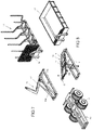
- FIG. 7 illustrates a hook device 15 installed on top of the module A3.
- the hook interchangeable device 15 comprises a frame surrounding 15a. To one end thereof, the hydraulic cylinders 16a and 16n have been pivoted, and to the other end the turning frame 17 of the hook device by bearings T. At their other end, the hydraulic cylinders are connected to the turning frame 17 of the hook device.
- the gripping hook K of the hook interchangeable platform device may be brought behind the gripping bar 18 in the load unit 12, whereby as the turning frame 17 of the hydraulic cylinders 16a, 16b is tilted, the load unit 12, a timber bunk interchangeable platform, that is, a log trailer frame in the embodiment, is pulled on top of the module A3.
- FIG 8 shows a second alternative outfit.
- the module A3 is equipped with a cable device 14. Its operation is as described on the basis of Figure 4 .
- the module A3 is equipped with a bogie G.
- FIG 9 shows an alternative module A1 which for the purpose of frame-steering comprises cylinders n1 and n2, which may be connected to the rearmost load unit module A3.
- the module comprises the bogie G.
- the bogie G is advantageously a driving bogie, so all the wheels of its axles get their driving force from an internal combustion engine or electric motor or hydraulic motor located in the module.
- the bogie G is additionally bearing-mounted to the module frame so as to rock or swing.
- Figure 10 shows the most common embodiment of the invention, in which the undercarriage A is a uniform structure consisting of one part.
- the module comprise the bearing ring H, rails u for the platform, to which the platform is fixed, and axles G1 and G2 at both ends of the frame A. Both the wheels of the front axles and the wheels of the rear axles are advantageously turning and driven wheels.
- the driving speed achievable by the multi-purpose work machine is the maximum speed for a traffic tractor.
- Figure 11 shows the centre module A2 which only comprises an axle G3 and rubber wheels on it, adapted to steer the multi-purpose work machine and thus being turning and hence steering.
- Figure 12 shows a bulldozer blade module A4.
- Figure 13 shows a boom embodiment 11, which comprises a bucket 11e.
- Figure 14 shows a boom embodiment which comprises a grab 11b or similar to grab logs or similar.
- the gripping jaws 11c and 11d of the grab 11b are motor-driven, such as cylinders, and a load may be squeezed between them.
- Figures 15 and 16 show a multi-purpose work machine provided with support legs 19 and comprises an additional power source 20 at one end of the module load unit module A3, which produces additional energy for the rear axles and rear wheels G10 for load transport purposes.
- FIG 17 shows an area X1 which in Figure 18 is shown in a larger scale.
- the modules A1 and A3 are connected to each other by a flange joint D.
- the bolts R are brought through the holes in the flanges, and a nut W is placed to the other end of each bolt R in question. By turning the nut, the flanges have been pulled against each other and the joint tightened. As a second connecting option there is welding. The modules are welded to each other.
- the multi-purpose work machine may by wheel-steered or frame-steered.
- the number of axles is 2 to 6.
- FIG 19 shows a solution with a fixed platform.
- the platform 12 is fixed to the module A3.
- the centre module A1 which comprises the slewing bearing ring H of the cabin 10, and the module A1 is further connected to the axle module A2.
- the modules A1, A2, A3 are interconnected by screw/flange joints in the manner of quick clamping.
- Figures 20 to 24 show a so-called frame-steer module A100.
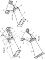
- the module half 101 it comprises a joint 102 for the cylinder n1, connected to a moving frame part R10, and a joint 103 at the other end of the cylinder n1, connected to a round frame plate R20 of the frame half 101.
- the frame part R10 is pivoted to turn (arrow S3) at joints 108 and 109 in relation to the frame R20.
- the cylinder n2 comprises a joint 105 in the module half 101 on its turning frame part R10, and a joint 106 at the other end of the cylinder, connected to the round frame plate R20 of the half on the other side of the centre line X.
- the cylinders n1 and n2 are advantageously hydraulic cylinders. They are thus used to turn the turning frame part R10 of the half 101 and thus a rotation and a turning motion S3 is performed between the frame halves 101 and 104.
- Joint axles 108, 109 pass through the lugs K1, K2 and the holes in the frame part R10.
- the lugs K1, K2 are welded to the round plate R20.
- the frame part R10 is formed of plate-like parts R10a and R10b, which connect to the flange part D10. So, a placement and moving space is formed for the cylinders n1 and n2 between the parts R10a and R10b.
- the frame part R10 with the structures connected to it are adapted to rotate on the joints 108, 109 in relation to the frame part R20.
- the frame part R20 of the half 101 is a round plate, which acts as the base frame part and is, together with the devices connected to it, adapted to rotate by means of a slewing ring bearing in relation to the other frame part 104.
- the turning ring bearing is thus between the halves 101 and 104.
- the half 104 is along its length L1 substantially longer than the half 101 along its length L2. It widens conically towards the connecting flange D20. The choice of the length makes sure that the module parts of the vehicle turn in relation to each other also in cases where the angle of the longitudinal axis of the load unit and drive unit has become large.
- the rotation of the frame half 104 is denoted by the arrow S2.
- the half 101 advantageously connects to the frame module A1 comprising a control cabin such as the cabin 10, and the half 104 advantageously connects to the frame module A3 comprising a platform or similar.
- the frame modules A1, A3 are turned by means of the cylinders n1 and n2 and thus the movable multi-purpose work machine is steered.
- the halves 101 and 104 connect to each other at swivel 107 which may comprise bearing elements f such as rolls or cone bearing parts or bearing rolls on the circumference.
- the swivel 107 allows the halves 101 and 104 to rotate (arrow S2) in relation to each other.
- the frame plate R10 of the half 101, with the parts connected thereto, are adapted to turn (arrow S2) in relation to the frame half 104 at the swivel bearing.
- the frame halves 101 and 104 of the halves may be locked in relation to each other for the duration of loading, for example, by the cylinder or brake 60. This may be implemented, for example, by locking the circumferences of the bearing to each other with the brake 60 or cylinder.
- the brake 60 comprises a brake piston 62.
- a brake piston 62 Through an opening 61, pressure oil is brought to the cylinder space and the brake piston 62 is pressed against the mating surface, and the rotation S2 of the bearing halves in relation to each other is prevented.
- the rotation S3 is at the same time prevented by locking the cylinders n1 and n2. This way, for the duration of loading, the joint A100 may be stiffened and the loading situation kept stable.
- the brake frame of the brake 60 is connected to one frame half 104, and as the piston 62 of the brake 60 is affected by the pressure of the hydraulic oil, the piston 62 is moved towards the other frame half 101, against its surface, whereby the frame halves 104, 101 are locked to each other and the rotation S2 is prevented.
- One frame half 101 comprises fastening means D10 and the other frame half 104 comprises fastening means D20.
- the module A100 may be detachably mounted to the different modules of the multi-purpose work machine advantageously so that the half 101 is connected to the cabin and control cabin module, and the half 104 is connected to the module comprising the load module.
- the fastening means D10 and D20 are in the embodiments of the figures formed of perforated flanges and screws and nuts, or only of screws and flanges as well as screws holes of the flanges.
- the connection of the frame steering module A100 to other modules may also be carried out by welding.
- the machine is of metal.
- Figure 25 shows a cross-section B-B of Figure 21 ,
- the round plate like base frame R20 of the frame half 101 with the structures R10, n1, n2 rotates on bearings 107 in relation to the frame half 104.
- the rotation is denoted by the arrow S2.
Landscapes
- Engineering & Computer Science (AREA)
- Mining & Mineral Resources (AREA)
- Civil Engineering (AREA)
- General Engineering & Computer Science (AREA)
- Structural Engineering (AREA)
- Mechanical Engineering (AREA)
- Chemical & Material Sciences (AREA)
- Combustion & Propulsion (AREA)
- Transportation (AREA)
- Body Structure For Vehicles (AREA)
- Automatic Assembly (AREA)
Claims (20)
- Eine Mehrzweckarbeitsmaschine umfassend einem oberen Wagen, das heißt einem oberen Rahmen (B), und darauf einer Kabine (10) und einem Mehrzweckausleger (11), die sich zusammen frei um eine vertikale Achse (Y) drehen, und welcher Mehrzweckausleger (11) ein Werkzeug umfasst, wie eine Schaufel (11e), das damit verbunden ist,und, unter dem oberen Wagen (B), einem Fahrgestell, das heißt einem unteren Rahmen (A) mit Achsen (50a, 51a...) und entsprechenden Rädern (50b, 51b...), und über dem Fahrgestell (A) einer Ladeinheit (12), wodurch der Ausleger (11) mit dem Werkzeug zum Laden auf die Ladeeinheit (12) dient,dadurch gekennzeichnet, dass die Ladeeinheit (12) eine austauschbare Plattform ist und dass die Mehrzweckarbeitsmaschine eine Hakenvorrichtung oder Kabelvorrichtung aufweist, um die Plattform auf den Boden abzusenken oder vom Boden über den unteren Rahmen (A) anzuheben.
- Eine Mehrzweckarbeitsmaschine nach Anspruch 1, dadurch gekennzeichnet, dass das Fahrgestell (A) eine Hakenvorrichtung (15) umfasst, die über ihren umgebenden Rahmen (15a) mit dem Fahrgestell an dessen Rahmen verbunden ist, wobei die Hakenvorrichtung (15) einen oder mehrere Hydraulikzylinder (16a, 16b) und einen Drehrahmen (17) der Hakenvorrichtung umfasst, der über ein Lager (T) an einem Ende des Drehrahmens geschwenkt wird, um vom Hydraulikzylinder (16a, 16b) gedreht zu werden, wodurch ein Haken (K) am anderen Ende des Rahmens (17) mit einem Griffbügel (18) auf der austauschbaren Plattform verbunden werden kann, wodurch die austauschbare Plattform (12) durch die Hakenvorrichtung (15) angehoben und über den Rahmen des Fahrgestells vom Boden und von über dem Rahmen auf den Boden abgesenkt werden kann.
- Eine Mehrzweckarbeitsmaschine nach Anspruch 1, dadurch gekennzeichnet, dass das Fahrgestell (A) eine Kabelvorrichtung (14) umfasst, die kippbare Schienen (P) umfasst, die an einem Ende ein oder mehrere Lager (T2) umfassen, wobei die dadurch abgestützten Schienen (P) gekippt werden können, und dass zwischen dem Rahmen (J) der Kabelvorrichtung (14) und den Schienen (P) ein oder mehrere Hydraulikzylinder (18a, 18b) vorhanden sind, die schwenkbar mit dem Rahmen (J) der Kabelvorrichtung und am anderen Ende schwenkbar mit den Schienen (P) verbunden sind, und dass Kabel (V) existieren, die über einen Motor (M) aufgewickelt werden können, um Rollen (O) an einem Ende der Schienen (P) aufwickeln zu können, und wobei das andere Ende des Kabels (V) mit der austauschbaren Plattform verbunden werden kann, wodurch, wenn die Schienen (P) durch die Zylindervorrichtung (18a, 18b) gekippt wurden, die austauschbare Plattform (12) durch Verwendung des Motors (M) auf die Schienen angehoben und die austauschbare Plattform (12) über die Schwerkraft von den Schienen (P) auf den Boden abgesenkt werden kann.
- Eine Mehrzweckarbeitsmaschine nach einem der vorstehenden Ansprüche, dadurch gekennzeichnet, dass sich die Kabine (10) und der Ausleger (11) um mindestens 360 Grad frei um die vertikale Achse (Y) der Maschine drehen, und dass
die Mehrzweckmaschine im Fahrgestell mindestens zwei Rahmenmodule (A1, A2, A3, A4) im Fahrgestell umfasst, die durchgängig miteinander verbunden sind. - Eine Mehrzweckarbeitsmaschine nach einem der vorstehenden Ansprüche, dadurch gekennzeichnet, dass der untere Rahmen, das heißt das Fahrgestell (A), mindestens zwei Rahmenmodule (A1, A2...) umfasst, die über Flanschverbindungen (D1, D2, D3...) miteinander verbunden sind, die somit als Verbindungsmittel zwischen den Modulen dienen.
- Eine Mehrzweckarbeitsmaschine nach Anspruch 5, dadurch gekennzeichnet, dass Bolzen und/oder Schrauben (R) bei den Flanschverbindungen verwendet werden.
- Eine Mehrzweckarbeitsmaschine nach einem der vorstehenden Ansprüche, dadurch gekennzeichnet, dass das Fahrgestell (A) ein Rahmenmodul (A1), das im Mittelbereich einen Lagerring (H) für die Kabine (10) besitzt, sowie Verbindungsflansche (D) an beiden Enden umfasst.
- Eine Mehrzweckarbeitsmaschine nach einem der vorstehenden Ansprüche, dadurch gekennzeichnet, dass der Mehrzweckausleger (110) ein Ausleger mit einem Greifer zum Greifen und Übertragen von Waren ist.
- Eine Mehrzweckarbeitsmaschine nach einem der vorstehenden Ansprüche 1 bis 7, dadurch gekennzeichnet, dass der Mehrzweckausleger (11) einen Backenbrecher oder gleichwertig umfasst.
- Eine Mehrzweckarbeitsmaschine nach einem der vorstehenden Ansprüche, dadurch gekennzeichnet, dass der untere Rahmen (A) mindestens ein erstes Rahmenmodul (A1) und ein zweites Rahmenmodul (A3) umfasst, dass das erste Rahmenmodul (A1) Hydraulikzylinder (n1, n2) umfasst, um das erste Rahmenmodul (A1) mit dem zweiten Rahmenmodul (A3) zu verbinden, damit eine Rahmenlenkung für die Mehrzweckarbeitsmaschine integriert werden kann, und dass das erste Rahmenmodul (A1) auf dessen oberen Fläche einen Lagerring (H) für die Kabine oder Steuerkabine (10) umfasst.
- Eine Mehrzweckarbeitsmaschine nach einem der vorstehenden Ansprüche, dadurch gekennzeichnet, dass das Fahrgestell ein Rahmenmodul (A2, A3) des Fahrgestells (A) mit einer Achse oder einem Drehgestell (G3, G) umfasst.
- Eine Mehrzweckarbeitsmaschine nach einem der vorstehenden Ansprüche, dadurch gekennzeichnet, dass, wie das Frontmodul (A4) des Fahrgestells (A), ein Modul mit einem Räumschild vorhanden ist.
- Eine Mehrzweckarbeitsmaschine nach Anspruch 10, dadurch gekennzeichnet, dass im Fahrgestell ein separates Rahmenlenkungsmodul (A100) vorhanden ist, das Verbindungsmittel (D10, D20) an beiden Enden des Moduls umfasst, um das Modul (A100) lösbar mit den Rahmenteilen der Mehrzweckarbeitsmaschine zu verbinden, und dass das Rahmenlenkungsmodul (A100) aus zwei Rahmenhälften (101, 104) besteht, die schwenkbar zueinander angeordnet sind, und dass die Rahmenhälften (101, 104) dazwischen ein Drehgelenk (107) umfassen, wodurch die Rahmenhälften (101, 104) in Bezug zueinander rotieren können (Pfeil S2), und dass ein Zylinder (n1) an seinem Ende schwenkbar mit einer Hälfte (101) zu dessen Drehrahmenteil (R10) verbunden ist und dass an dessen anderem Ende der Zylinder (n1) schwenkbar mit dem Rahmenteil (R20) verbunden ist, und wobei ebenso der zweite Zylinder (n2) schenkbar mit einer Hälfte (101) zu dessen Drehrahmenteil (R10) und an dessen anderem Ende schwenkbar mit dem Rahmenteil (R20) verbunden ist, und dass das erste (D10) der Verbindungsmittel in einer Hälfte (101) und das zweite Verbindungsmittel (D20) in der anderen Hälfte (104) des Moduls (A100) untergebracht ist.
- Eine Mehrzweckarbeitsmaschine nach Anspruch 13, dadurch gekennzeichnet, dass die Verbindungsmittel (D10, D20) aus einem gelochten Flansch geformt sind und dass der Rahmenteil (101) einen Basisrahmenteil (R20) und, drehbar damit verbunden, einen beweglichen Rahmenteil (R10) umfasst, der einen Verbindungsflansch (D10) umfasst, und wobei ein drehbares Gelenk (108, 109) zwischen den Rahmenteilen (R10 und R20) angeordnet ist und dass die rotierende Drehbewegung (S3) des Teils (R10) mit Zylindern (n1, n2) ausgeführt wird und dass der Teil (R20) mit damit verbundenen Strukturen in Bezug zur Hälfte (104) am Drehgelenk (107) rotierbar ist (S2), und dass die Hälfte (104) mit dem Lademodul (A3) über eine Flanschverbindung oder durch Schweißen verbunden werden kann und dass die Rahmenhälfte (101) mit dem Modul mit der Kabine (10) über eine Flanschverbindung oder durch Schweißen verbunden ist.
- Eine Mehrzweckarbeitsmaschine nach Anspruch 14, dadurch gekennzeichnet, dass das Drehgelenk (107) aus Rollmitteln (f) auf einem Ring, wie Lagerrollen oder Lagerkugeln oder Kugellagern, besteht.
- Eine Mehrzweckarbeitsmaschine nach Anspruch 1, dadurch gekennzeichnet, dass die Steuerkabine (10) eine Kabine mit der Lenkanlage der Maschine und Raum für einen Maschinenbediener ist.
- Eine Mehrzweckarbeitsmaschine nach Anspruch 1, dadurch gekennzeichnet, dass die Kabine (10) eine Basis für Fernbedienungsmittel, wie eine Kamera, darstellt.
- Eine Mehrzweckarbeitsmaschine nach Anspruch 4, dadurch gekennzeichnet, dass die Rahmenmodule (A1, A2, A100, A3) durch Schweißen miteinander verbunden sind.
- Eine Mehrzweckarbeitsmaschine nach einem der vorstehenden Ansprüche, dadurch gekennzeichnet, dass der Ausleger (11) mit einem Werkzeug, wie einer Schaufel (11e), dafür ausgelegt ist, sich nicht nur mit der Kabine (10) um die vertikale Achse (Y), sondern auch in Bezug dazu an einem Gelenk (11a) um die vertikale Achse (Y1) parallel zur vertikalen Achse (Y) zu drehen, wobei der Ausleger (11) das Gelenk (11a) für die entsprechende Drehung aufweist.
- Eine Mehrzweckarbeitsmaschine nach einem der Ansprüche 13, 14 oder 15, dadurch gekennzeichnet, dass das Drehgelenk (107) des Rahmenlenkungsmoduls (A100) mit einer Bremse (60) bereitgestellt wird, über welche die Rotation (S2) der Rahmenhälften in Bezug zueinander verhindert wird, wodurch das Rahmenlenkungsmodul (A100) für die Ladedauer der Mehrzweckarbeitsmaschine versteift werden kann, um bei Ladevorgang und Betätigung des Auslegers (11) stabil zu bleiben.
Priority Applications (1)
| Application Number | Priority Date | Filing Date | Title |
|---|---|---|---|
| PL18171813T PL3401446T3 (pl) | 2017-05-12 | 2018-05-11 | Wielofunkcyjna maszyna robocza |
Applications Claiming Priority (1)
| Application Number | Priority Date | Filing Date | Title |
|---|---|---|---|
| FIU20174132U FI12142U1 (fi) | 2017-05-12 | 2017-05-12 | Monitoimityökone |
Publications (2)
| Publication Number | Publication Date |
|---|---|
| EP3401446A1 EP3401446A1 (de) | 2018-11-14 |
| EP3401446B1 true EP3401446B1 (de) | 2021-09-22 |
Family
ID=63489957
Family Applications (1)
| Application Number | Title | Priority Date | Filing Date |
|---|---|---|---|
| EP18171813.1A Active EP3401446B1 (de) | 2017-05-12 | 2018-05-11 | Mehrzweckarbeitsmaschine |
Country Status (4)
| Country | Link |
|---|---|
| EP (1) | EP3401446B1 (de) |
| ES (1) | ES2901463T3 (de) |
| FI (1) | FI12142U1 (de) |
| PL (1) | PL3401446T3 (de) |
Family Cites Families (6)
| Publication number | Priority date | Publication date | Assignee | Title |
|---|---|---|---|---|
| DE9314191U1 (de) * | 1993-09-21 | 1994-01-05 | Helmut Völker GmbH & Co, 64759 Sensbachtal | Erdbaumaschine |
| DE29708637U1 (de) * | 1997-05-15 | 1997-07-24 | Bergmann, Johannes Hermann, 49733 Haren | Kombinations-Arbeitsfahrzeuge mit schwenkbarem Fahrerstand |
| US20100044124A1 (en) * | 2005-11-23 | 2010-02-25 | Radke Daniel D | Articulated Dozer With Suspension And Suspension Lockout |
| SE533130C2 (sv) * | 2007-02-05 | 2010-07-06 | Rolf Volungholen | Fordon för avverkning av skog och/eller transport av virkesbitar |
| SE537571C2 (sv) * | 2013-10-10 | 2015-06-23 | Komatsu Forest Ab | Anordning för att anpassa marktrycket hos ett terränggåendemotorfordon och ett terränggående motorfordon utrustad med en sådan anordning |
| EP2939876A1 (de) * | 2014-04-30 | 2015-11-04 | Pris-Mag S.r.l. | Kipper mit einem System zur Befestigung eines Behälters mittels hydraulischer Spannelemente |
-
2017
- 2017-05-12 FI FIU20174132U patent/FI12142U1/fi active IP Right Grant
-
2018
- 2018-05-11 PL PL18171813T patent/PL3401446T3/pl unknown
- 2018-05-11 EP EP18171813.1A patent/EP3401446B1/de active Active
- 2018-05-11 ES ES18171813T patent/ES2901463T3/es active Active
Also Published As
| Publication number | Publication date |
|---|---|
| ES2901463T3 (es) | 2022-03-22 |
| FI12142U1 (fi) | 2018-09-14 |
| EP3401446A1 (de) | 2018-11-14 |
| PL3401446T3 (pl) | 2022-02-07 |
Similar Documents
| Publication | Publication Date | Title |
|---|---|---|
| EP3401447B1 (de) | Auf kettenschienen fahrende maschine | |
| CN105569102B (zh) | 工作机 | |
| CN101808849B (zh) | 车架可扩展的作业车 | |
| US8103418B2 (en) | Extendable frame work vehicle having lift member movable in a true vertical fashion | |
| KR100899274B1 (ko) | 반궤도식 작업차 | |
| KR102657223B1 (ko) | 작업 기계용 하부 주행체 | |
| JP2016094817A (ja) | 作業機械 | |
| JPS58139992A (ja) | 大型伸縮クレ−ン | |
| KR20160052391A (ko) | 작업 기계용 하부 주행체 | |
| US10822209B1 (en) | Lift attachment apparatus | |
| EP3330212B1 (de) | Mobiler kran | |
| US3989149A (en) | Excavating device | |
| US20160280118A1 (en) | Construction Machine Transport | |
| CN209025120U (zh) | 矿用多用履带式牵引挖掘机随车吊 | |
| EP3401446A1 (de) | Mehrzweckarbeitsmaschine | |
| RU2045465C1 (ru) | Универсальный трактор | |
| US6336558B1 (en) | Tractor unit and wheeled trailer combination | |
| RU2169673C2 (ru) | Кран-манипулятор лесовозный | |
| US11479453B1 (en) | Lift attachment apparatus | |
| JP2799768B2 (ja) | 掘削積込ロボットによる地盤の掘削方法 | |
| CN214460751U (zh) | 一种多功能一体式工程车 | |
| FI12141U1 (fi) | Telaketjuilla liikkuva kone | |
| WO1989011006A1 (en) | Material handling machine | |
| US12404152B1 (en) | Lift attachment apparatus | |
| RU2783560C1 (ru) | Роботизированный многофункциональный трактор-вездеход |
Legal Events
| Date | Code | Title | Description |
|---|---|---|---|
| PUAI | Public reference made under article 153(3) epc to a published international application that has entered the european phase |
Free format text: ORIGINAL CODE: 0009012 |
|
| STAA | Information on the status of an ep patent application or granted ep patent |
Free format text: STATUS: THE APPLICATION HAS BEEN PUBLISHED |
|
| AK | Designated contracting states |
Kind code of ref document: A1 Designated state(s): AL AT BE BG CH CY CZ DE DK EE ES FI FR GB GR HR HU IE IS IT LI LT LU LV MC MK MT NL NO PL PT RO RS SE SI SK SM TR |
|
| AX | Request for extension of the european patent |
Extension state: BA ME |
|
| STAA | Information on the status of an ep patent application or granted ep patent |
Free format text: STATUS: REQUEST FOR EXAMINATION WAS MADE |
|
| 17P | Request for examination filed |
Effective date: 20190513 |
|
| RBV | Designated contracting states (corrected) |
Designated state(s): AL AT BE BG CH CY CZ DE DK EE ES FI FR GB GR HR HU IE IS IT LI LT LU LV MC MK MT NL NO PL PT RO RS SE SI SK SM TR |
|
| STAA | Information on the status of an ep patent application or granted ep patent |
Free format text: STATUS: EXAMINATION IS IN PROGRESS |
|
| 17Q | First examination report despatched |
Effective date: 20200722 |
|
| GRAP | Despatch of communication of intention to grant a patent |
Free format text: ORIGINAL CODE: EPIDOSNIGR1 |
|
| STAA | Information on the status of an ep patent application or granted ep patent |
Free format text: STATUS: GRANT OF PATENT IS INTENDED |
|
| INTG | Intention to grant announced |
Effective date: 20210330 |
|
| GRAS | Grant fee paid |
Free format text: ORIGINAL CODE: EPIDOSNIGR3 |
|
| GRAA | (expected) grant |
Free format text: ORIGINAL CODE: 0009210 |
|
| STAA | Information on the status of an ep patent application or granted ep patent |
Free format text: STATUS: THE PATENT HAS BEEN GRANTED |
|
| RAP3 | Party data changed (applicant data changed or rights of an application transferred) |
Owner name: IDEA - KEKSI OY |
|
| RIN1 | Information on inventor provided before grant (corrected) |
Inventor name: MANTSINEN, YRJOE JUHANI |
|
| AK | Designated contracting states |
Kind code of ref document: B1 Designated state(s): AL AT BE BG CH CY CZ DE DK EE ES FI FR GB GR HR HU IE IS IT LI LT LU LV MC MK MT NL NO PL PT RO RS SE SI SK SM TR |
|
| REG | Reference to a national code |
Ref country code: GB Ref legal event code: FG4D |
|
| REG | Reference to a national code |
Ref country code: IE Ref legal event code: FG4D |
|
| REG | Reference to a national code |
Ref country code: DE Ref legal event code: R096 Ref document number: 602018023812 Country of ref document: DE |
|
| REG | Reference to a national code |
Ref country code: CH Ref legal event code: EP Ref country code: AT Ref legal event code: REF Ref document number: 1432433 Country of ref document: AT Kind code of ref document: T Effective date: 20211015 |
|
| REG | Reference to a national code |
Ref country code: FI Ref legal event code: FGE |
|
| REG | Reference to a national code |
Ref country code: SE Ref legal event code: TRGR |
|
| REG | Reference to a national code |
Ref country code: LT Ref legal event code: MG9D |
|
| REG | Reference to a national code |
Ref country code: NL Ref legal event code: MP Effective date: 20210922 |
|
| PG25 | Lapsed in a contracting state [announced via postgrant information from national office to epo] |
Ref country code: HR Free format text: LAPSE BECAUSE OF FAILURE TO SUBMIT A TRANSLATION OF THE DESCRIPTION OR TO PAY THE FEE WITHIN THE PRESCRIBED TIME-LIMIT Effective date: 20210922 Ref country code: RS Free format text: LAPSE BECAUSE OF FAILURE TO SUBMIT A TRANSLATION OF THE DESCRIPTION OR TO PAY THE FEE WITHIN THE PRESCRIBED TIME-LIMIT Effective date: 20210922 Ref country code: BG Free format text: LAPSE BECAUSE OF FAILURE TO SUBMIT A TRANSLATION OF THE DESCRIPTION OR TO PAY THE FEE WITHIN THE PRESCRIBED TIME-LIMIT Effective date: 20211222 Ref country code: LT Free format text: LAPSE BECAUSE OF FAILURE TO SUBMIT A TRANSLATION OF THE DESCRIPTION OR TO PAY THE FEE WITHIN THE PRESCRIBED TIME-LIMIT Effective date: 20210922 Ref country code: NO Free format text: LAPSE BECAUSE OF FAILURE TO SUBMIT A TRANSLATION OF THE DESCRIPTION OR TO PAY THE FEE WITHIN THE PRESCRIBED TIME-LIMIT Effective date: 20211222 |
|
| REG | Reference to a national code |
Ref country code: AT Ref legal event code: MK05 Ref document number: 1432433 Country of ref document: AT Kind code of ref document: T Effective date: 20210922 Ref country code: EE Ref legal event code: FG4A Ref document number: E021824 Country of ref document: EE Effective date: 20211207 |
|
| PG25 | Lapsed in a contracting state [announced via postgrant information from national office to epo] |
Ref country code: LV Free format text: LAPSE BECAUSE OF FAILURE TO SUBMIT A TRANSLATION OF THE DESCRIPTION OR TO PAY THE FEE WITHIN THE PRESCRIBED TIME-LIMIT Effective date: 20210922 Ref country code: GR Free format text: LAPSE BECAUSE OF FAILURE TO SUBMIT A TRANSLATION OF THE DESCRIPTION OR TO PAY THE FEE WITHIN THE PRESCRIBED TIME-LIMIT Effective date: 20211223 |
|
| REG | Reference to a national code |
Ref country code: ES Ref legal event code: FG2A Ref document number: 2901463 Country of ref document: ES Kind code of ref document: T3 Effective date: 20220322 |
|
| PG25 | Lapsed in a contracting state [announced via postgrant information from national office to epo] |
Ref country code: AT Free format text: LAPSE BECAUSE OF FAILURE TO SUBMIT A TRANSLATION OF THE DESCRIPTION OR TO PAY THE FEE WITHIN THE PRESCRIBED TIME-LIMIT Effective date: 20210922 |
|
| PG25 | Lapsed in a contracting state [announced via postgrant information from national office to epo] |
Ref country code: IS Free format text: LAPSE BECAUSE OF FAILURE TO SUBMIT A TRANSLATION OF THE DESCRIPTION OR TO PAY THE FEE WITHIN THE PRESCRIBED TIME-LIMIT Effective date: 20220122 Ref country code: SK Free format text: LAPSE BECAUSE OF FAILURE TO SUBMIT A TRANSLATION OF THE DESCRIPTION OR TO PAY THE FEE WITHIN THE PRESCRIBED TIME-LIMIT Effective date: 20210922 Ref country code: RO Free format text: LAPSE BECAUSE OF FAILURE TO SUBMIT A TRANSLATION OF THE DESCRIPTION OR TO PAY THE FEE WITHIN THE PRESCRIBED TIME-LIMIT Effective date: 20210922 Ref country code: PT Free format text: LAPSE BECAUSE OF FAILURE TO SUBMIT A TRANSLATION OF THE DESCRIPTION OR TO PAY THE FEE WITHIN THE PRESCRIBED TIME-LIMIT Effective date: 20220124 Ref country code: NL Free format text: LAPSE BECAUSE OF FAILURE TO SUBMIT A TRANSLATION OF THE DESCRIPTION OR TO PAY THE FEE WITHIN THE PRESCRIBED TIME-LIMIT Effective date: 20210922 Ref country code: AL Free format text: LAPSE BECAUSE OF FAILURE TO SUBMIT A TRANSLATION OF THE DESCRIPTION OR TO PAY THE FEE WITHIN THE PRESCRIBED TIME-LIMIT Effective date: 20210922 |
|
| REG | Reference to a national code |
Ref country code: DE Ref legal event code: R097 Ref document number: 602018023812 Country of ref document: DE |
|
| PG25 | Lapsed in a contracting state [announced via postgrant information from national office to epo] |
Ref country code: DK Free format text: LAPSE BECAUSE OF FAILURE TO SUBMIT A TRANSLATION OF THE DESCRIPTION OR TO PAY THE FEE WITHIN THE PRESCRIBED TIME-LIMIT Effective date: 20210922 |
|
| PLBE | No opposition filed within time limit |
Free format text: ORIGINAL CODE: 0009261 |
|
| STAA | Information on the status of an ep patent application or granted ep patent |
Free format text: STATUS: NO OPPOSITION FILED WITHIN TIME LIMIT |
|
| 26N | No opposition filed |
Effective date: 20220623 |
|
| PG25 | Lapsed in a contracting state [announced via postgrant information from national office to epo] |
Ref country code: SI Free format text: LAPSE BECAUSE OF FAILURE TO SUBMIT A TRANSLATION OF THE DESCRIPTION OR TO PAY THE FEE WITHIN THE PRESCRIBED TIME-LIMIT Effective date: 20210922 |
|
| REG | Reference to a national code |
Ref country code: BE Ref legal event code: MM Effective date: 20220531 |
|
| PG25 | Lapsed in a contracting state [announced via postgrant information from national office to epo] |
Ref country code: MC Free format text: LAPSE BECAUSE OF FAILURE TO SUBMIT A TRANSLATION OF THE DESCRIPTION OR TO PAY THE FEE WITHIN THE PRESCRIBED TIME-LIMIT Effective date: 20210922 Ref country code: LU Free format text: LAPSE BECAUSE OF NON-PAYMENT OF DUE FEES Effective date: 20220511 |
|
| PG25 | Lapsed in a contracting state [announced via postgrant information from national office to epo] |
Ref country code: IE Free format text: LAPSE BECAUSE OF NON-PAYMENT OF DUE FEES Effective date: 20220511 |
|
| PG25 | Lapsed in a contracting state [announced via postgrant information from national office to epo] |
Ref country code: BE Free format text: LAPSE BECAUSE OF NON-PAYMENT OF DUE FEES Effective date: 20220531 |
|
| PG25 | Lapsed in a contracting state [announced via postgrant information from national office to epo] |
Ref country code: HU Free format text: LAPSE BECAUSE OF FAILURE TO SUBMIT A TRANSLATION OF THE DESCRIPTION OR TO PAY THE FEE WITHIN THE PRESCRIBED TIME-LIMIT; INVALID AB INITIO Effective date: 20180511 |
|
| PG25 | Lapsed in a contracting state [announced via postgrant information from national office to epo] |
Ref country code: SM Free format text: LAPSE BECAUSE OF FAILURE TO SUBMIT A TRANSLATION OF THE DESCRIPTION OR TO PAY THE FEE WITHIN THE PRESCRIBED TIME-LIMIT Effective date: 20210922 Ref country code: MK Free format text: LAPSE BECAUSE OF FAILURE TO SUBMIT A TRANSLATION OF THE DESCRIPTION OR TO PAY THE FEE WITHIN THE PRESCRIBED TIME-LIMIT Effective date: 20210922 Ref country code: CY Free format text: LAPSE BECAUSE OF FAILURE TO SUBMIT A TRANSLATION OF THE DESCRIPTION OR TO PAY THE FEE WITHIN THE PRESCRIBED TIME-LIMIT Effective date: 20210922 |
|
| PGFP | Annual fee paid to national office [announced via postgrant information from national office to epo] |
Ref country code: CZ Payment date: 20240502 Year of fee payment: 7 |
|
| PG25 | Lapsed in a contracting state [announced via postgrant information from national office to epo] |
Ref country code: MT Free format text: LAPSE BECAUSE OF FAILURE TO SUBMIT A TRANSLATION OF THE DESCRIPTION OR TO PAY THE FEE WITHIN THE PRESCRIBED TIME-LIMIT Effective date: 20210922 |
|
| REG | Reference to a national code |
Ref country code: DE Ref legal event code: R082 Ref document number: 602018023812 Country of ref document: DE Representative=s name: WUESTHOFF & WUESTHOFF PATENTANWAELTE UND RECHT, DE |
|
| PGFP | Annual fee paid to national office [announced via postgrant information from national office to epo] |
Ref country code: ES Payment date: 20250812 Year of fee payment: 8 |
|
| PG25 | Lapsed in a contracting state [announced via postgrant information from national office to epo] |
Ref country code: TR Free format text: LAPSE BECAUSE OF FAILURE TO SUBMIT A TRANSLATION OF THE DESCRIPTION OR TO PAY THE FEE WITHIN THE PRESCRIBED TIME-LIMIT Effective date: 20210922 |
|
| PG25 | Lapsed in a contracting state [announced via postgrant information from national office to epo] |
Ref country code: CZ Free format text: LAPSE BECAUSE OF NON-PAYMENT OF DUE FEES Effective date: 20250511 |
|
| REG | Reference to a national code |
Ref country code: CH Ref legal event code: U11 Free format text: ST27 STATUS EVENT CODE: U-0-0-U10-U11 (AS PROVIDED BY THE NATIONAL OFFICE) Effective date: 20260601 |
|
| PGFP | Annual fee paid to national office [announced via postgrant information from national office to epo] |
Ref country code: GB Payment date: 20260527 Year of fee payment: 9 Ref country code: PL Payment date: 20260510 Year of fee payment: 9 |
|
| PGFP | Annual fee paid to national office [announced via postgrant information from national office to epo] |
Ref country code: IT Payment date: 20260527 Year of fee payment: 9 |
|
| PGFP | Annual fee paid to national office [announced via postgrant information from national office to epo] |
Ref country code: DE Payment date: 20260528 Year of fee payment: 9 |
|
| PGFP | Annual fee paid to national office [announced via postgrant information from national office to epo] |
Ref country code: SE Payment date: 20260527 Year of fee payment: 9 Ref country code: FI Payment date: 20260527 Year of fee payment: 9 |
|
| PGFP | Annual fee paid to national office [announced via postgrant information from national office to epo] |
Ref country code: CH Payment date: 20260601 Year of fee payment: 9 |
|
| PGFP | Annual fee paid to national office [announced via postgrant information from national office to epo] |
Ref country code: EE Payment date: 20260528 Year of fee payment: 9 |
|
| PGFP | Annual fee paid to national office [announced via postgrant information from national office to epo] |
Ref country code: FR Payment date: 20260528 Year of fee payment: 9 |