EP3397399B1 - Continuous additive manufacturing methods - Google Patents
Continuous additive manufacturing methods Download PDFInfo
- Publication number
- EP3397399B1 EP3397399B1 EP16882299.7A EP16882299A EP3397399B1 EP 3397399 B1 EP3397399 B1 EP 3397399B1 EP 16882299 A EP16882299 A EP 16882299A EP 3397399 B1 EP3397399 B1 EP 3397399B1
- Authority
- EP
- European Patent Office
- Prior art keywords
- actinic radiation
- adhesive
- transparent substrate
- substrate
- precursor composition
- Prior art date
- Legal status (The legal status is an assumption and is not a legal conclusion. Google has not performed a legal analysis and makes no representation as to the accuracy of the status listed.)
- Active
Links
Images


Classifications
-
- C—CHEMISTRY; METALLURGY
- C09—DYES; PAINTS; POLISHES; NATURAL RESINS; ADHESIVES; COMPOSITIONS NOT OTHERWISE PROVIDED FOR; APPLICATIONS OF MATERIALS NOT OTHERWISE PROVIDED FOR
- C09J—ADHESIVES; NON-MECHANICAL ASPECTS OF ADHESIVE PROCESSES IN GENERAL; ADHESIVE PROCESSES NOT PROVIDED FOR ELSEWHERE; USE OF MATERIALS AS ADHESIVES
- C09J7/00—Adhesives in the form of films or foils
- C09J7/30—Adhesives in the form of films or foils characterised by the adhesive composition
- C09J7/38—Pressure-sensitive adhesives [PSA]
- C09J7/381—Pressure-sensitive adhesives [PSA] based on macromolecular compounds obtained by reactions involving only carbon-to-carbon unsaturated bonds
- C09J7/385—Acrylic polymers
-
- B—PERFORMING OPERATIONS; TRANSPORTING
- B05—SPRAYING OR ATOMISING IN GENERAL; APPLYING FLUENT MATERIALS TO SURFACES, IN GENERAL
- B05D—PROCESSES FOR APPLYING FLUENT MATERIALS TO SURFACES, IN GENERAL
- B05D3/00—Pretreatment of surfaces to which liquids or other fluent materials are to be applied; After-treatment of applied coatings, e.g. intermediate treating of an applied coating preparatory to subsequent applications of liquids or other fluent materials
- B05D3/06—Pretreatment of surfaces to which liquids or other fluent materials are to be applied; After-treatment of applied coatings, e.g. intermediate treating of an applied coating preparatory to subsequent applications of liquids or other fluent materials by exposure to radiation
- B05D3/061—Pretreatment of surfaces to which liquids or other fluent materials are to be applied; After-treatment of applied coatings, e.g. intermediate treating of an applied coating preparatory to subsequent applications of liquids or other fluent materials by exposure to radiation using U.V.
- B05D3/065—After-treatment
- B05D3/067—Curing or cross-linking the coating
-
- B—PERFORMING OPERATIONS; TRANSPORTING
- B05—SPRAYING OR ATOMISING IN GENERAL; APPLYING FLUENT MATERIALS TO SURFACES, IN GENERAL
- B05D—PROCESSES FOR APPLYING FLUENT MATERIALS TO SURFACES, IN GENERAL
- B05D5/00—Processes for applying liquids or other fluent materials to surfaces to obtain special surface effects, finishes or structures
- B05D5/10—Processes for applying liquids or other fluent materials to surfaces to obtain special surface effects, finishes or structures to obtain an adhesive surface
-
- B—PERFORMING OPERATIONS; TRANSPORTING
- B23—MACHINE TOOLS; METAL-WORKING NOT OTHERWISE PROVIDED FOR
- B23K—SOLDERING OR UNSOLDERING; WELDING; CLADDING OR PLATING BY SOLDERING OR WELDING; CUTTING BY APPLYING HEAT LOCALLY, e.g. FLAME CUTTING; WORKING BY LASER BEAM
- B23K26/00—Working by laser beam, e.g. welding, cutting or boring
- B23K26/08—Devices involving relative movement between laser beam and workpiece
- B23K26/082—Scanning systems, i.e. devices involving movement of the laser beam relative to the laser head
-
- B—PERFORMING OPERATIONS; TRANSPORTING
- B29—WORKING OF PLASTICS; WORKING OF SUBSTANCES IN A PLASTIC STATE IN GENERAL
- B29C—SHAPING OR JOINING OF PLASTICS; SHAPING OF MATERIAL IN A PLASTIC STATE, NOT OTHERWISE PROVIDED FOR; AFTER-TREATMENT OF THE SHAPED PRODUCTS, e.g. REPAIRING
- B29C64/00—Additive manufacturing, i.e. manufacturing of three-dimensional [3D] objects by additive deposition, additive agglomeration or additive layering, e.g. by 3D printing, stereolithography or selective laser sintering
- B29C64/10—Processes of additive manufacturing
- B29C64/106—Processes of additive manufacturing using only liquids or viscous materials, e.g. depositing a continuous bead of viscous material
- B29C64/124—Processes of additive manufacturing using only liquids or viscous materials, e.g. depositing a continuous bead of viscous material using layers of liquid which are selectively solidified
- B29C64/129—Processes of additive manufacturing using only liquids or viscous materials, e.g. depositing a continuous bead of viscous material using layers of liquid which are selectively solidified characterised by the energy source therefor, e.g. by global irradiation combined with a mask
-
- B—PERFORMING OPERATIONS; TRANSPORTING
- B29—WORKING OF PLASTICS; WORKING OF SUBSTANCES IN A PLASTIC STATE IN GENERAL
- B29C—SHAPING OR JOINING OF PLASTICS; SHAPING OF MATERIAL IN A PLASTIC STATE, NOT OTHERWISE PROVIDED FOR; AFTER-TREATMENT OF THE SHAPED PRODUCTS, e.g. REPAIRING
- B29C64/00—Additive manufacturing, i.e. manufacturing of three-dimensional [3D] objects by additive deposition, additive agglomeration or additive layering, e.g. by 3D printing, stereolithography or selective laser sintering
- B29C64/20—Apparatus for additive manufacturing; Details thereof or accessories therefor
- B29C64/245—Platforms or substrates
-
- B—PERFORMING OPERATIONS; TRANSPORTING
- B33—ADDITIVE MANUFACTURING TECHNOLOGY
- B33Y—ADDITIVE MANUFACTURING, i.e. MANUFACTURING OF THREE-DIMENSIONAL [3D] OBJECTS BY ADDITIVE DEPOSITION, ADDITIVE AGGLOMERATION OR ADDITIVE LAYERING, e.g. BY 3D PRINTING, STEREOLITHOGRAPHY OR SELECTIVE LASER SINTERING
- B33Y70/00—Materials specially adapted for additive manufacturing
-
- C—CHEMISTRY; METALLURGY
- C09—DYES; PAINTS; POLISHES; NATURAL RESINS; ADHESIVES; COMPOSITIONS NOT OTHERWISE PROVIDED FOR; APPLICATIONS OF MATERIALS NOT OTHERWISE PROVIDED FOR
- C09J—ADHESIVES; NON-MECHANICAL ASPECTS OF ADHESIVE PROCESSES IN GENERAL; ADHESIVE PROCESSES NOT PROVIDED FOR ELSEWHERE; USE OF MATERIALS AS ADHESIVES
- C09J7/00—Adhesives in the form of films or foils
- C09J7/20—Adhesives in the form of films or foils characterised by their carriers
- C09J7/29—Laminated material
-
- B—PERFORMING OPERATIONS; TRANSPORTING
- B05—SPRAYING OR ATOMISING IN GENERAL; APPLYING FLUENT MATERIALS TO SURFACES, IN GENERAL
- B05D—PROCESSES FOR APPLYING FLUENT MATERIALS TO SURFACES, IN GENERAL
- B05D1/00—Processes for applying liquids or other fluent materials
- B05D1/28—Processes for applying liquids or other fluent materials performed by transfer from the surfaces of elements carrying the liquid or other fluent material, e.g. brushes, pads, rollers
- B05D1/286—Processes for applying liquids or other fluent materials performed by transfer from the surfaces of elements carrying the liquid or other fluent material, e.g. brushes, pads, rollers using a temporary backing to which the coating has been applied
-
- B—PERFORMING OPERATIONS; TRANSPORTING
- B05—SPRAYING OR ATOMISING IN GENERAL; APPLYING FLUENT MATERIALS TO SURFACES, IN GENERAL
- B05D—PROCESSES FOR APPLYING FLUENT MATERIALS TO SURFACES, IN GENERAL
- B05D2252/00—Sheets
- B05D2252/02—Sheets of indefinite length
-
- B—PERFORMING OPERATIONS; TRANSPORTING
- B33—ADDITIVE MANUFACTURING TECHNOLOGY
- B33Y—ADDITIVE MANUFACTURING, i.e. MANUFACTURING OF THREE-DIMENSIONAL [3D] OBJECTS BY ADDITIVE DEPOSITION, ADDITIVE AGGLOMERATION OR ADDITIVE LAYERING, e.g. BY 3D PRINTING, STEREOLITHOGRAPHY OR SELECTIVE LASER SINTERING
- B33Y10/00—Processes of additive manufacturing
-
- B—PERFORMING OPERATIONS; TRANSPORTING
- B33—ADDITIVE MANUFACTURING TECHNOLOGY
- B33Y—ADDITIVE MANUFACTURING, i.e. MANUFACTURING OF THREE-DIMENSIONAL [3D] OBJECTS BY ADDITIVE DEPOSITION, ADDITIVE AGGLOMERATION OR ADDITIVE LAYERING, e.g. BY 3D PRINTING, STEREOLITHOGRAPHY OR SELECTIVE LASER SINTERING
- B33Y30/00—Apparatus for additive manufacturing; Details thereof or accessories therefor
-
- B—PERFORMING OPERATIONS; TRANSPORTING
- B33—ADDITIVE MANUFACTURING TECHNOLOGY
- B33Y—ADDITIVE MANUFACTURING, i.e. MANUFACTURING OF THREE-DIMENSIONAL [3D] OBJECTS BY ADDITIVE DEPOSITION, ADDITIVE AGGLOMERATION OR ADDITIVE LAYERING, e.g. BY 3D PRINTING, STEREOLITHOGRAPHY OR SELECTIVE LASER SINTERING
- B33Y80/00—Products made by additive manufacturing
-
- C—CHEMISTRY; METALLURGY
- C09—DYES; PAINTS; POLISHES; NATURAL RESINS; ADHESIVES; COMPOSITIONS NOT OTHERWISE PROVIDED FOR; APPLICATIONS OF MATERIALS NOT OTHERWISE PROVIDED FOR
- C09J—ADHESIVES; NON-MECHANICAL ASPECTS OF ADHESIVE PROCESSES IN GENERAL; ADHESIVE PROCESSES NOT PROVIDED FOR ELSEWHERE; USE OF MATERIALS AS ADHESIVES
- C09J2301/00—Additional features of adhesives in the form of films or foils
- C09J2301/20—Additional features of adhesives in the form of films or foils characterized by the structural features of the adhesive itself
- C09J2301/21—Additional features of adhesives in the form of films or foils characterized by the structural features of the adhesive itself the adhesive layer being formed by alternating adhesive areas of different nature
-
- C—CHEMISTRY; METALLURGY
- C09—DYES; PAINTS; POLISHES; NATURAL RESINS; ADHESIVES; COMPOSITIONS NOT OTHERWISE PROVIDED FOR; APPLICATIONS OF MATERIALS NOT OTHERWISE PROVIDED FOR
- C09J—ADHESIVES; NON-MECHANICAL ASPECTS OF ADHESIVE PROCESSES IN GENERAL; ADHESIVE PROCESSES NOT PROVIDED FOR ELSEWHERE; USE OF MATERIALS AS ADHESIVES
- C09J2301/00—Additional features of adhesives in the form of films or foils
- C09J2301/30—Additional features of adhesives in the form of films or foils characterized by the chemical, physicochemical or physical properties of the adhesive or the carrier
- C09J2301/302—Additional features of adhesives in the form of films or foils characterized by the chemical, physicochemical or physical properties of the adhesive or the carrier the adhesive being pressure-sensitive, i.e. tacky at temperatures inferior to 30°C
-
- C—CHEMISTRY; METALLURGY
- C09—DYES; PAINTS; POLISHES; NATURAL RESINS; ADHESIVES; COMPOSITIONS NOT OTHERWISE PROVIDED FOR; APPLICATIONS OF MATERIALS NOT OTHERWISE PROVIDED FOR
- C09J—ADHESIVES; NON-MECHANICAL ASPECTS OF ADHESIVE PROCESSES IN GENERAL; ADHESIVE PROCESSES NOT PROVIDED FOR ELSEWHERE; USE OF MATERIALS AS ADHESIVES
- C09J2301/00—Additional features of adhesives in the form of films or foils
- C09J2301/30—Additional features of adhesives in the form of films or foils characterized by the chemical, physicochemical or physical properties of the adhesive or the carrier
- C09J2301/304—Additional features of adhesives in the form of films or foils characterized by the chemical, physicochemical or physical properties of the adhesive or the carrier the adhesive being heat-activatable, i.e. not tacky at temperatures inferior to 30°C
-
- C—CHEMISTRY; METALLURGY
- C09—DYES; PAINTS; POLISHES; NATURAL RESINS; ADHESIVES; COMPOSITIONS NOT OTHERWISE PROVIDED FOR; APPLICATIONS OF MATERIALS NOT OTHERWISE PROVIDED FOR
- C09J—ADHESIVES; NON-MECHANICAL ASPECTS OF ADHESIVE PROCESSES IN GENERAL; ADHESIVE PROCESSES NOT PROVIDED FOR ELSEWHERE; USE OF MATERIALS AS ADHESIVES
- C09J2301/00—Additional features of adhesives in the form of films or foils
- C09J2301/40—Additional features of adhesives in the form of films or foils characterized by the presence of essential components
- C09J2301/416—Additional features of adhesives in the form of films or foils characterized by the presence of essential components use of irradiation
-
- C—CHEMISTRY; METALLURGY
- C09—DYES; PAINTS; POLISHES; NATURAL RESINS; ADHESIVES; COMPOSITIONS NOT OTHERWISE PROVIDED FOR; APPLICATIONS OF MATERIALS NOT OTHERWISE PROVIDED FOR
- C09J—ADHESIVES; NON-MECHANICAL ASPECTS OF ADHESIVE PROCESSES IN GENERAL; ADHESIVE PROCESSES NOT PROVIDED FOR ELSEWHERE; USE OF MATERIALS AS ADHESIVES
- C09J2433/00—Presence of (meth)acrylic polymer
-
- C—CHEMISTRY; METALLURGY
- C09—DYES; PAINTS; POLISHES; NATURAL RESINS; ADHESIVES; COMPOSITIONS NOT OTHERWISE PROVIDED FOR; APPLICATIONS OF MATERIALS NOT OTHERWISE PROVIDED FOR
- C09J—ADHESIVES; NON-MECHANICAL ASPECTS OF ADHESIVE PROCESSES IN GENERAL; ADHESIVE PROCESSES NOT PROVIDED FOR ELSEWHERE; USE OF MATERIALS AS ADHESIVES
- C09J2463/00—Presence of epoxy resin
-
- C—CHEMISTRY; METALLURGY
- C09—DYES; PAINTS; POLISHES; NATURAL RESINS; ADHESIVES; COMPOSITIONS NOT OTHERWISE PROVIDED FOR; APPLICATIONS OF MATERIALS NOT OTHERWISE PROVIDED FOR
- C09J—ADHESIVES; NON-MECHANICAL ASPECTS OF ADHESIVE PROCESSES IN GENERAL; ADHESIVE PROCESSES NOT PROVIDED FOR ELSEWHERE; USE OF MATERIALS AS ADHESIVES
- C09J2475/00—Presence of polyurethane
Definitions
- the present disclosure relates to continuous methods for additive manufacturing of adhesives.
- an adhesive such as a pressure sensitive adhesive, a hot melt adhesive, or a structural adhesive.
- an adhesive such as a pressure sensitive adhesive, a hot melt adhesive, or a structural adhesive.
- WO 2014/186265 A1 discloses a multilayer pressure sensitive adhesive assembly comprising at least a first pressure sensitive adhesive layer superimposed to a second polymer layer, wherein a curable liquid precursor of the first pressure sensitive adhesive polymer layer comprises a low Tg (meth)acrylate copolymer and a high Tg (meth)acrylate copolymer having a weight average molecular weight (Mw) of above 20,000 Daltons.
- WO 96/14215 A1 discloses optical security articles comprising a first layer substantially transparent to visible light and having a first refractive index, the first layer having a relief pattern on a first surface thereof and a substantially smooth second surface, and an adhesive layer coterminating with the first layer.
- the adhesive layer substantially completely fills and makes contact with a first portion of the plurality of geometric concavities, the adhesive layer having a second refractive index which is substantially similar to the first refractive index of the first layer.
- a second portion of the plurality of geometric concavities are precluded from contact with the adhesive layer by a corresponding plurality of separation layers, each separation layer having a separation layer refractive index which is different from the refractive index of the first layer.
- WO 2012/166460 A2 discloses methods for making differentially pattern cured microstructured articles, using a molding tool having a microstructured surface, a patterned irradiation to generate irradiated and non-irradiated regions in a radiation curable resin.
- the present disclosure relates to additive manufacturing of adhesives. It has been discovered that there exists a need for additional methods for manufacturing adhesives, such as continuous methods.
- a continuous method of making an adhesive includes obtaining an actinic radiation-polymerizable adhesive precursor composition disposed on a major surface of an actinic radiation-transparent substrate and irradiating a first portion of the actinic radiation-polymerizable adhesive precursor composition through the actinic radiation-transparent substrate for a first irradiation dosage to form a first adhesive.
- the method further includes moving the actinic radiation-transparent substrate and irradiating a second portion of the actinic radiation-polymerizable adhesive precursor composition through the actinic radiation-transparent substrate for a second irradiation dosage to form a second adhesive.
- the first adhesive and the second adhesive are individual adhesives separated from each other by approximately the distance the actinic radiation-transparent substrate was moved.
- an actinic radiation-polymerizable adhesive precursor composition disposed on a major surface of an actinic radiation-transparent substrate and irradiating a first portion of the actinic radiation-polymerizable adhesive precursor composition through the actinic radiation-transparent substrate for a first irradiation dosage.
- the method further includes irradiating a second portion of the actinic radiation-polymerizable adhesive precursor composition through the actinic radiation-transparent substrate for a second irradiation dosage and moving the actinic radiation-transparent substrate.
- the first portion and the second portion are adjacent to or overlapping with each other and the first irradiation dosage and the second irradiation dosage are not the same, thereby forming an integral adhesive having a variable thickness in an axis normal to the actinic radiation-transparent substrate.
- the present disclosure provides methods for the additive manufacturing of adhesives, such as continuous manufacturing of the adhesives.
- integral adhesives having variations in thickness are formed, while in other embodiments a plurality of adhesives having approximately the same thickness are formed.
- actinic radiation refers to electromagnetic radiation that can produce photochemical reactions.
- doctor means a level of exposure to of actinic radiation.
- integral means composed of parts that together constitute a whole.
- (co)polymer is inclusive of both homopolymers containing a single monomer and copolymers containing two or more different monomers.
- (meth)acrylic or "(meth)acrylate” is inclusive of both acrylic and methacrylic (or acrylate and methacrylate). Acrylate and methacrylate monomers, oligomers, or polymers are referred to collectively herein as "acrylates”.
- aliphatic group means a saturated or unsaturated linear or branched hydrocarbon group. This term is used to encompass alkyl, alkenyl, and alkynyl groups, for example.
- alkyl group means a saturated hydrocarbon group that is linear, branched, cyclic, or combinations thereof and typically has 1 to 20 carbon atoms. In some embodiments, the alkyl group contains 1 to 18, 1 to 12, 1 to 10, 1 to 8, 1 to 6, or 1 to 4 carbon atoms. Examples of alkyl group include without limitation, methyl, ethyl, isopropyl, t-butyl, heptyl, dodecyl, octadecyl, amyl, 2-ethylhexyl, and the like.
- alkylene group refers to a divalent alkyl group.
- alicyclic group means a cyclic hydrocarbon group having properties resembling those of aliphatic groups.
- aromatic group or “aryl group” means a mono- or polynuclear aromatic hydrocarbon group.
- pattern with respect to an adhesive refers to a design of an adhesive that defines at least one aperture in the adhesive.
- solvent refers to a substance that dissolves another substance to form a solution.
- total monomer refers to the combination of all monomers in an adhesive composition, including both in a polymerized reaction product and in optional additional materials.
- a continuous method in a first aspect, includes obtaining an actinic radiation-polymerizable adhesive precursor composition disposed on a major surface of an actinic radiation-transparent substrate and irradiating a first portion of the actinic radiation-polymerizable adhesive precursor composition through the actinic radiation-transparent substrate for a first irradiation dosage to form a first adhesive.
- the method further includes moving the actinic radiation-transparent substrate and irradiating a second portion of the actinic radiation-polymerizable adhesive precursor composition through the actinic radiation-transparent substrate for a second irradiation dosage to form a second adhesive.
- an actinic radiation-polymerizable adhesive precursor composition disposed on a major surface of an actinic radiation-transparent substrate and irradiating a first portion of the actinic radiation-polymerizable adhesive precursor composition through the actinic radiation-transparent substrate for a first irradiation dosage.
- the method further includes irradiating a second portion of the actinic radiation-polymerizable adhesive precursor composition through the actinic radiation-transparent substrate for a second irradiation dosage and moving the actinic radiation-transparent substrate.
- the first portion and the second portion are adjacent to or overlapping with each other and the first irradiation dosage and the second irradiation dosage are not the same, thereby forming an integral adhesive having a variable thickness in an axis normal to the actinic radiation-transparent substrate.
- the below disclosure relates to both the first and second aspects.
- a continuous method can form a series or array of individual adhesives each separated from each other by approximately the distance the substrate was moved in between irradiation of the separate adhesives.
- the individual adhesives in some embodiments have the same dimensions of height, length, and width as each other.
- the individual adhesives in other embodiments differ from each other in at least one of height (i.e., z-direction from a major surface of the substrate), length, and width.
- the methods of the present disclosure provide the capability to easily manufacture individual adhesives having a number of unique shapes due to employing adaptable actinic radiation sources, from which the bounds and dosage of the actinic radiation determine the specific shape of an individual adhesive.
- digital light projectors, laser scanning devices, and liquid crystal displays can all be controlled to change the area and intensity of the actinic radiation that causes curing of the actinic radiation-polymerizable adhesive precursor composition.
- die-cutting of an adhesive is not readily capable of forming adhesives having a wedge shape. Similarly, die-cutting is not amenable to forming an adhesive that has a height gradient or other unique shapes.
- the (continuous) methods of the present disclosure not only provide a wide variety of shapes and gradients, but also can manufacture multiple different shapes and heights on the same substrate.
- methods of the first aspect further comprise irradiating a third portion of the actinic radiation-polymerizable adhesive precursor composition through the actinic radiation-transparent substrate prior to moving the substrate, wherein the first portion and the third portion are adjacent to or overlapping with each other.
- an integral adhesive is formed comprising a variable thickness in an axis normal to the actinic radiation-transparent substrate.
- the time of irradiation of the first dosage is shorter or longer than the time of irradiation of the third dosage.
- the actinic radiation intensity of the first dosage is lower or higher than the actinic radiation intensity of the third dosage.
- irradiating the first portion occurs before irradiating the third portion, at the same time as irradiating the third portion, or a combination thereof.
- methods of the first aspect further comprise irradiating a fourth portion of the actinic radiation-polymerizable adhesive precursor composition through the actinic radiation-transparent substrate.
- a second integral adhesive comprising a variable thickness in an axis normal to the major surface of the actinic radiation-transparent substrate.
- the time of irradiation of the second dosage is shorter or longer than the time of irradiation of the fourth dosage.
- the actinic radiation intensity of the second dosage is lower or higher than the actinic radiation intensity of the fourth dosage.
- irradiating the second portion occurs before irradiating the fourth portion, at the same time as irradiating the fourth portion, or a combination thereof.
- the method comprises applying the same irradiation dosage to a number of different portions of the actinic radiation-polymerizable adhesive precursor composition (e.g., to both the first portion and the third portion), thereby forming a pattern of adhesive having the same thickness in an axis normal to the major surface of the actinic radiation-transparent substrate.
- the pattern includes one or more individual adhesives that can be either integral or separate from one or more other individual adhesives of the same height.
- methods of the second aspect further comprise irradiating a third portion of the actinic radiation-polymerizable adhesive precursor composition through the actinic radiation-transparent substrate for a third irradiation dosage, after moving the substrate.
- the first irradiation dosage and the third irradiation dosage are the same or different.
- methods of the second aspect may further comprise irradiating a fourth portion of the actinic radiation-polymerizable adhesive precursor composition through the actinic radiation-transparent substrate for a fourth irradiation dosage.
- the third portion and the fourth portion are adjacent to or overlapping with each other and the third irradiation dosage and the fourth irradiation dosage are not the same, thereby forming an integral adhesive.
- the actinic radiation-transparent substrate is moved after irradiating the fourth portion of the actinic radiation-polymerizable adhesive precursor composition through the actinic radiation-transparent substrate.
- the (e.g., integral) adhesive is a pressure sensitive adhesive (PSA), a structural adhesive, a structural hybrid adhesive, a hot melt adhesive, or a combination thereof.
- PSA pressure sensitive adhesive
- the adhesive is often prepared from an actinic radiation-polymerizable adhesive precursor composition comprising an acrylate, a two-part acrylate and epoxy system, a two-part acrylate and urethane system, or a combination thereof.
- the actinic radiation-polymerizable adhesive precursor composition is a 100% polymerizable precursor composition, while in other embodiments the actinic radiation-polymerizable adhesive precursor composition comprises at least one solvent, such as for instance and without limitation C4-C12 alkanes (e.g., heptanes), alcohols (e.g., methanol, ethanol, or isopropanol), ethers, and esters.
- solvent such as for instance and without limitation C4-C12 alkanes (e.g., heptanes), alcohols (e.g., methanol, ethanol, or isopropanol), ethers, and esters.
- the acrylic polymer can be, for example, an acrylic acid ester of a non-tertiary alcohol having from 1 to 18 carbon atoms.
- the acrylic acid ester includes a carbon-to-carbon chain having 4 to 12 carbon atoms and terminates at the hydroxyl oxygen atom, the chain containing at least half of the total number of carbon atoms in the molecule.
- acrylic acid esters are polymerizable to a tacky, stretchable, and elastic adhesive.
- acrylic acid esters of nontertiary alcohols include but are not limited to 2-methylbutyl acrylate, isooctyl acrylate, lauryl acrylate, 4-methyl-2-pentyl acrylate, isoamyl acrylate, sec-butyl acrylate, n-butyl acrylate, n-hexyl acrylate, 2- ethylhexyl acrylate, n-octyl acrylate, n-decyl acrylate, isodecyl acrylate, isodecyl methacrylate, and isononyl acrylate.
- Suitable acrylic acid esters of non tertiary alcohols include, for example, 2-ethylhexyl acrylate and isooctylacrylate.
- the acrylic acid ester may be copolymerized with one or more monoethylenically unsaturated monomers that have highly polar groups.
- monoethylenically unsaturated monomer such as acrylic acid, methacrylic acid, itaconic acid, acrylamide, methacrylamide, N- substituted acrylamides (for example, N,N-dimethyl acrylamide), acrylonitrile, methacrylonitrile, hydroxyalkyl acrylates, cyanoethyl acrylate, N-vinylpyrrolidone, N-vinylcaprolactam, and maleic anhydride.
- these copolymerizable monomers are used in amounts of less than 20% by weight of the adhesive matrix such that the adhesive is tacky at ordinary room temperatures. In some cases, tackiness can be preserved at up to 50% by weight of N-vinylpyrrolidone.
- acrylate copolymers comprising at least 6% by weight acrylic acid, and in other embodiments, at least 8% by weight, or at least 10% by weight acrylic acid, each based on the total weight of the monomers in the acrylate copolymer.
- the adhesive may also include small amounts of other useful copolymerizable monoethylenically unsaturated monomers such as alkyl vinyl ethers, vinylidene chloride, styrene, and vinyltoluene.
- adhesives according to the present disclosure comprise two-part acrylate and epoxy systems.
- suitable acrylate-epoxy compositions are described in detail in U.S. Application Publication No. 2003/0236362 (Bluem et al. )
- adhesives according to the present disclosure comprise two-part acrylate and urethane systems.
- suitable acrylate-urethane compositions are described in detail in U.S. Patent No. 4,950,696 (Palazotto et al. )
- Enhancement of the cohesive strength of the adhesive may also be achieved through the use of a crosslinking agent such as 1,6-hexanediol diacrylate, with a photoactive triazine crosslinking agent such as taught in U.S. Patent Nos. 4,330,590 (Vesley ) and 4,329,384 (Vesley et al. ), or with a heat-activatable crosslinking agent such as a lower-alkoxylated amino formaldehyde condensate having C1-4 alkyl groups-for example, hexamethoxymethyl melamine or tetramethoxymethyl urea or tetrabutoxymethyl urea.
- Crosslinking may be achieved by irradiating the composition with electron beam (or "e-beam") radiation, gamma radiation, or x-ray radiation.
- Bisamide crosslinkers may be used with acrylic adhesives in solution.
- a monomer mixture may be irradiated with actinic radiation, such as for example ultraviolet (UV) rays, in the presence of a photopolymerization initiator (i.e., photoinitiators).
- actinic radiation such as for example ultraviolet (UV) rays
- photopolymerization initiator i.e., photoinitiators
- Suitable exemplary photoinitiators are those available under the trade designations IRGACURE and DAROCUR from BASF (Ludwigshafen, Germany) and include 1-hydroxycyclohexyl phenyl ketone (IRGACURE 184), 2,2-dimethoxy-1,2-diphenylethan-1-one (IRGACURE 651), bis(2,4,6-trimethylbenzoyl)phenylphosphineoxide (IRGACURE 819), 1-[4-(2-hydroxyethoxy)phenyl]-2-hydroxy-2-methyl-1-propane-1-one (IRGACURE 2959), 2-benzyl-2-dimethylamino-1-(4-morpholinophenyl)butanone (IRGACURE 369), 2-methyl-1-[4-(methylthio)phenyl]-2-morpholinopropan-1-one (IRGACURE 907), Oligo[2-hydroxy-2-methyl-1-[4- (1-methylvinyl)phenyl]propanone]
- photoinitiators include for example and without limitation, benzyl dimethyl ketal, 2-methyl-2-hydroxypropiophenone, benzoin methyl ether, benzoin isopropyl ether, anisoin methyl ether, aromatic sulfonyl chlorides, photoactive oximes, and combinations thereof.
- a photoinitiator is typically present in an amount between about 0.01 to about 5.0 parts, or from 0.1 to 1.5 parts, per 100 parts by weight of total monomer.
- the method comprises post-curing the one or more formed adhesives (e.g., the first adhesive, the second adhesive, the integral adhesive, etc.), for instance post-curing using actinic radiation or heat.
- the one or more formed adhesives e.g., the first adhesive, the second adhesive, the integral adhesive, etc.
- actinic radiation or heat for instance, by not requiring an adhesive to be cured to the full extent needed for a particular application during an initial irradiation, radiation variables can be focused on polymerizing to form a desired shape and size.
- the post-cure of the adhesive is optionally initiated using a thermal initiator.
- Suitable thermal initiators include for example and without limitation, 2,2'-azobis(2,4-dimethylvaleronitrile), 2,2'-azobisoisobutyronitrile (VAZO 64, available from E.I. du Pont de Nemours Co.), 2,2'-azobis(2,4-dimethylpentanenitrile) (VAZO 52, available from E.I.
- the method often further comprises removing actinic radiation-polymerizable adhesive precursor composition remaining in contact with the adhesives (e.g., the first adhesive, the second adhesive, the integral adhesive, etc.).
- Removing precursor composition that has not been polymerized after the irradiating may involve the use of gravity, a gas, a vacuum, a fluid, or any combination thereof.
- a suitable fluid for removing excess adhesive precursor composition includes a solvent.
- the temperature(s) at which methods according to the present disclosure are performed is not particularly limited. For methods employing an actinic radiation-polymerizable adhesive precursor composition that is in a liquid form at room temperature (e.g., 20-25 degrees Celsius), for simplicity at least some of the various steps of the method are typically performed at room temperature. For methods employing an actinic radiation-polymerizable adhesive precursor composition that is in a solid form at room temperature, at least some of the various steps of the method may be performed at an elevated temperature above room temperature such that the actinic radiation-polymerizable adhesive precursor composition is in a liquid form.
- Elevated temperatures may be used through an entire method, or through such steps as formation of an adhesive, removal of unpolymerized actinic radiation-polymerizable adhesive precursor composition, and/or optional post-curing of the adhesive. In some embodiments, certain portions of the method are performed at different temperatures, whereas in some other embodiments, the entire method is performed at one temperature. Suitable elevated temperatures include for instance and without limitation, above 25 degrees Celsius and up to 150 degrees Celsius, up to 130 degrees Celsius, up to 110 degrees Celsius, up to 100 degrees Celsius, up to 90 degrees Celsius, up to 80 degrees Celsius, up to 70 degrees Celsius, up to 60 degrees Celsius, up to 50 degrees Celsius, or up to 40 degrees Celsius.
- the method is performed at a temperature between 20 degrees Celsius and 150 degrees Celsius, inclusive; between 30 degrees Celsius and 150 degrees Celsius, inclusive; between 25 degrees Celsius and 100 degrees Celsius, inclusive; or between 25 degrees Celsius and 70 degrees Celsius, inclusive.
- the temperature employed is typically limited only by the lowest maximum temperature at which a material used in the method (e.g., a substrate, an apparatus component, etc.) remains thermally stable.
- the method is performed on an apparatus that is separate from other materials used in an end application for the one or more formed adhesives.
- the method further comprises removing the first integral adhesive from the substrate, as discussed in further detail below.
- the resulting adhesive is an adhesive due to its ability to adhere two materials together. Characteristics such as specific peel force, tackiness, etc., are not particularly limited as long as the formed adhesive adheres two material together (e.g., two layers in a multilayer construction, two components of a device, and the like). Typically, such a test involves disposing the formed adhesive between two substrates (one or both may be polymeric, glass, ceramic, or metal), lifting the article by the edges of one of the substrates, and observing whether or not the second substrate remains attached to the article.
- two substrates one or both may be polymeric, glass, ceramic, or metal
- the adhesive comprises variations in index of refraction.
- variations are typically formed as artifacts of the irradiation of the actinic radiation-polymerizable adhesive precursor composition with the various irradiation sources.
- an integral adhesive having variability in its thickness often there will be a variation in the index of refraction between the portions of the integral adhesive that were subjected to different dosages to form the variability in the thickness.
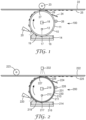
- the apparatus includes an actinic radiation-transparent substrate 10 having a major surface 11 and an irradiation source 12 configured to direct actinic radiation through the actinic radiation-transparent substrate 10 at predetermined dosages at predetermined locations.
- the apparatus 100 further includes a means for depositing 14 a composition 16 onto the major surface 11 of the actinic radiation-transparent substrate 10 and a means for conveying 18 the actinic radiation-transparent substrate 10 or the irradiation source 12 with respect to each other.
- a means for depositing 14 a composition 16 onto the major surface 11 of the actinic radiation-transparent substrate 10 and a means for conveying 18 the actinic radiation-transparent substrate 10 or the irradiation source 12 with respect to each other.
- the means for depositing 14 a composition 16 onto the major surface 11 of the actinic radiation-transparent substrate 10 comprises an open container holding a volume of the composition 16 positioned adjacent to the substrate 10 such that a portion of the major surface 11 of the substrate 10 is in contact with the composition 16.
- the contact deposits the composition 16 on the major surface 11 of the substrate 10, then as the means for conveying 18 the substrate 10 rotates, the composition 16 continues to be deposited on the portions of the major surface 11 of the substrate 10 that come into contact with the composition 16 held in the container 14.
- the apparatus 100 further comprises an air knife 20 configured to remove a composition from the substrate.
- Air knives are well known in the art and use compressed air to blow off contaminants, excess materials, etc. from a product or apparatus.
- the apparatus optionally further comprises a second substrate 22.
- the substrate is not particularly limited in material or surface structure; for example the second substrate 22 illustrated in FIG. 1 comprises a structured sheet, in which at least one major surface 25 of the sheet is structured (as opposed to flat and featureless).
- Suitable sheet materials include for instance and without limitation, polymeric materials selected from polyethylene terephthalate, polyethylene naphthalate, polycarbonate, polyimide, cycloolefin films, poly(methyl methacrylate), or a combination thereof.
- the second substrate may be a film, such as a single layer film or multilayer film having either a smooth surface or structured surface. Suitable structured surfaces include microstructured surfaces or embossed surfaces.
- a second substrate is employed to remove an adhesive from the actinic radiation-transparent substrate following irradiation from the actinic radiation.
- the second substrate 22 can be secured adjacent to and separate from the actinic radiation-transparent substrate 10 using a roller 23 or other suitable means.
- the apparatus 100 further comprises a scraper 24 configured to scrape the substrate and/or a tacky roller 26 configured to clean the substrate.
- a scraper 24 configured to scrape the substrate and/or a tacky roller 26 configured to clean the substrate.
- Other cleaning mechanisms for removing adhesive and/or un-polymerized composition from the substrate could alternatively be employed to prepare the substrate for the deposition of additional composition on its major surface, e.g., washing with a solvent.
- the substrate comprises a release material coated on the major surface of the substrate to enhance the ease of removal of the adhesive formed on the substrate. Suitable release materials include for instance and without limitation, silicone materials and low adhesion coatings.
- a suitable low adhesion coating can be coated as a solution of polyvinyl N-octadecyl carbamate and a blend of silicone resins, as described in U.S. Pat. No. 5,531,855 (Heinecke et al. )
- the actinic radiation-transparent substrate 10 is in the form of a cylinder.
- the means for depositing 14 a composition 16 on a cylindrical substrate 10 may comprise rotating the cylinder (e.g., actinic radiation-transparent substrate) through a volume of the composition 16 to apply the composition 16 on the major surface 11 of the substrate 10.
- rotating the cylinder e.g., actinic radiation-transparent substrate
- the apparatus shown in FIG. 1 is operated as follows: A means for conveying 18 the actinic radiation-transparent substrate 10 rotates the actinic radiation-transparent substrate 10 through the means for depositing 14 a composition 16, thereby depositing the composition 16 on the major surface 11 of the substrate 10 with which it contacts.
- An irradiation source 12 directs radiation through the actinic radiation-transparent substrate 10 at one or more predetermined dosages at one or more predetermined locations.
- the composition 16 that has been irradiated at least partially polymerizes, forming at least one adhesive, such as the adhesive 17 and the adhesive 19, shown in FIG. 1 .
- the adhesive 17 comprises a variation in thickness as a result of the specific irradiation provided by the irradiation source 12.
- an air knife 20 directs air towards the major surface 11 of the substrate 10 to assist in removing the composition 16 remaining on the major surface 11 of the substrate 10 that was not polymerized to form an adhesive.
- the excess composition 16 is preferably returned to the container 14 via gravity once it is no longer deposited on the substrate 10.
- a formed adhesive e.g., the adhesive 27 and the adhesive 29
- the adhesive (27, 29) is transferred from the major surface 11 of the substrate 10 to a major surface 25 of the second substrate 22.
- a scraper 24 contacts the major surface 11 of the substrate 10 and removes residual adhesive from the substrate 10.
- a tacky roller 26 contacts the major surface 11 of the substrate and removes residual adhesive from the substrate 10. It will be understood that not every apparatus 100 will include both or either of a scraper 24 and a tacky roller 26, as these can be optional components.
- a method may include obtaining an actinic radiation-polymerizable adhesive precursor composition 16 disposed on a major surface 11 of an actinic radiation-transparent substrate 10 and irradiating a first portion of the actinic radiation-polymerizable adhesive precursor composition through the actinic radiation-transparent substrate 10 for a first irradiation dosage to form a first adhesive 19.
- the method further includes moving the actinic radiation-transparent substrate 10 and irradiating a second portion of the actinic radiation-polymerizable adhesive precursor composition through the actinic radiation-transparent substrate 10 for a second irradiation dosage to form a second adhesive 17.
- an integral adhesive 19 is formed comprising a variable thickness in an axis normal to the actinic radiation-transparent substrate 10 when the first irradiation dosage and the third irradiation dosage are not the same.
- a method may include obtaining an actinic radiation-polymerizable adhesive precursor composition 16 disposed on a major surface 11 of an actinic radiation-transparent substrate 10 and irradiating a first portion of the actinic radiation-polymerizable adhesive precursor composition through the actinic radiation-transparent substrate 10 for a first irradiation dosage. The method further includes irradiating a second portion of the actinic radiation-polymerizable adhesive precursor composition through the actinic radiation-transparent substrate for a second irradiation dosage and moving the actinic radiation-transparent substrate.
- the first portion and the second portion are adjacent to or overlapping with each other and the first irradiation dosage and the second irradiation dosage are not the same, thereby forming an integral adhesive 19 having a variable thickness in an axis normal to the actinic radiation-transparent substrate 10.
- the apparatus includes an actinic radiation-transparent substrate 210 having a major surface 211 and an irradiation source 212 configured to direct actinic radiation through the actinic radiation-transparent substrate 210 at predetermined dosages at predetermined locations.
- the apparatus 200 further includes a means for depositing 214 a composition 216 onto the major surface 211 of the actinic radiation-transparent substrate 210 and a means for conveying 218 the actinic radiation-transparent substrate 210 or the irradiation source 212 with respect to each other.
- the apparatus 200 of certain embodiments includes a second irradiation source 232 configured to irradiate one or more adhesives (e.g., the adhesive 227 and the adhesive 229) through a second substrate 222 as they pass by the second irradiation source 232.
- a second irradiation source 232 is effective to post-cure the one or more adhesives.
- the second substrate 222 is often a consumable material obtained separately from the apparatus, and in the illustrated embodiment, comprises a structured sheet, in which at least one major surface 225 of the sheet is structured (as opposed to flat and featureless).
- the second substrate 222 can be secured adjacent to and separate from the actinic radiation-transparent substrate 210 using a roller 223 or other suitable means.
- the apparatus 200 shown in FIG. 2 further includes an actinic radiation-transparent film 230 having a major surface 231.
- the actinic radiation-transparent film 230 is wrapped at least partially around the actinic radiation-transparent substrate 210, and acts to protect the major surface 211 of the substrate 210 from residual composition 216 and adhesive material resistant to cleaning.
- the apparatus 200 operates similarly to the apparatus 100 of FIG. 1 described above, including that the composition 216 that has been irradiated at least partially polymerizes, forming at least one adhesive, such as the adhesive 217 and the adhesive 219.
- a formed adhesive e.g., the adhesive 227 and the adhesive 229
- the adhesive (227, 229) is transferred from the major surface 211 of the substrate 210 to a major surface 225 of the second substrate 222.
- the formed adhesive (227, 229) is irradiated by the second irradiation source 232 to post-cure the adhesive prior to transfer from the (first) substrate 210 to the second substrate 222.
- the apparatus includes an actinic radiation-transparent substrate 310 having a major surface 311 and an irradiation source 312 configured to direct actinic radiation through the actinic radiation-transparent substrate 310 at predetermined dosages at predetermined locations.
- the apparatus 300 further includes a means for depositing 314 a composition 316 onto the major surface 311 of the actinic radiation-transparent substrate 310 and a means for conveying 318 the actinic radiation-transparent substrate 310 or the irradiation source 312 with respect to each other.
- the apparatus 300 further comprises an air knife 320 configured to remove nonpolymerized composition 316 from the substrate 310, as well as a plurality of second irradiation sources 332 configured to irradiate one or more adhesives (e.g., the adhesive 327 and the adhesive 329) through a second substrate 322 as they pass by the second irradiation source 332.
- the use of at least one second irradiation source 332 is effective to post-cure the one or more adhesives.
- the second substrate 322 is often a consumable material obtained separately from the apparatus, and in the illustrated embodiment, comprises a smooth sheet.
- the second substrate 322 can be secured adjacent to and separate from the actinic radiation-transparent substrate 310 using a roller 323 or other suitable means.
- the apparatus 300 further comprises a scraper 324 configured to scrape the substrate 310 and/or a tacky roller 326 configured to clean the substrate 310.
- the apparatus 300 operates similarly to the apparatus 100 of FIG. 1 described above, including that the composition 316 that has been irradiated at least partially polymerizes, forming at least one adhesive, such as the adhesive 317 and the adhesive 319.
- a formed adhesive e.g., the adhesive 327 and the adhesive 329
- the adhesive (327, 329) is transferred from the major surface 311 of the substrate 310 to a major surface 325 of the second substrate 322.
- the formed adhesive (327, 329) is irradiated by one or more second irradiation sources 332 to post-cure the adhesive prior to transfer from the (first) substrate 310 to the second substrate 322.
- the apparatus 400 includes an actinic radiation-transparent substrate 410 having a major surface 411 and an irradiation source 412 configured to direct actinic radiation through the actinic radiation-transparent substrate 410 at predetermined dosages at predetermined locations.
- the apparatus 400 further includes a means for depositing 414 a composition 416 onto the major surface 411 of the actinic radiation-transparent substrate 410 and a means for conveying 418 the actinic radiation-transparent substrate 410 or the irradiation source 412 with respect to each other.
- an air knife 420 configured to remove nonpolymerized composition 416 from the substrate 410 is provided with the apparatus.
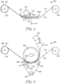
- the schematic of the apparatus 400 shown in FIG. 4 further comprises a mechanism 440 configured to remove one or more adhesives (e.g., the adhesive 429) through a second substrate 422 as they pass by the mechanism.
- the mechanism can be a robotic mechanism having a movable arm 442 and a replaceable end effector 444 configured to detach one or more adhesives 429 from the actinic radiation-transparent substrate 410.
- the end effector 444 comprises a major surface 445 configured to be shaped to be an inverse of the shape of an upper major surface of the adhesive 429.
- the mechanism 440 is typically configured to place the adhesive 429 in a location separate from the apparatus 400, such as on another substrate, on a device, on a release liner, in a storage container, etc.
- the apparatus 400 further comprises a scraper 424 configured to scrape the substrate 410 and/or a tacky roller 426 configured to clean the substrate 410.
- the apparatus 400 operates similarly to the apparatus 100 of FIG. 1 described above, including that the composition 416 that has been irradiated at least partially polymerizes, forming at least one adhesive, such as the adhesive 417 and the adhesive 419.
- a formed adhesive e.g., the adhesive 427 and the adhesive 429
- the mechanism 440 via rotation of the actinic radiation-transparent substrate 410, the adhesive (427, 429) is transferred from the major surface 411 of the substrate 410 to a major surface 445 of the end effector 444 of the mechanism 440.
- the apparatus includes at least two rollers 552 and 518 (at least one of which is configured to convey an actinic radiation-transparent substrate 510), and an irradiation source 512 configured to direct actinic radiation through the actinic radiation-transparent substrate 510 at predetermined dosages at predetermined locations.
- the apparatus 500 further includes a means for depositing 514 a composition 516 onto a major surface 511 of the actinic radiation-transparent substrate 510 and a means for conveying 518 the actinic radiation-transparent substrate 510 or the irradiation source 512 with respect to each other.
- the means for depositing 514 comprises a container configured to dispense the composition 516 as a pool on the major surface 511 of the substrate 510.
- the actinic radiation-transparent substrate 510 is often a consumable material obtained separately from the apparatus as opposed to being a component of the apparatus.
- an air knife 520 configured to remove nonpolymerized composition 516 from the substrate 510 where one or more adhesives 517 and 519 are formed is provided with the apparatus 500.
- a means for conveying 518 the actinic radiation-transparent substrate 510 drives a web of the actinic radiation-transparent substrate 510 through a plurality of rollers 550 that form a containment area to hold the composition 516 supplied by the means for depositing 514 the composition 516 on the major surface 511 of the substrate 510 with which it contacts.
- the means for depositing 514 in this embodiment is a container disposed above the actinic radiation-transparent substrate 510.
- An irradiation source 512 directs radiation through the actinic radiation-transparent substrate 510 at one or more predetermined dosages at one or more predetermined locations.
- the adhesive 517 comprises a variation in width as compared to the adhesive 519, as a result of the specific irradiation provided by the irradiation source 512.
- an air knife 520 directs air towards the major surface 511 of the substrate 510 to assist in removing the composition 516 remaining on the major surface 511 of the substrate 510 that was not polymerized to form an adhesive.
- the excess composition 516 is preferably returned to the containment area defined by the plurality of rollers 550. Once a formed adhesive (e.g., the adhesive 527 and the adhesive 529) reaches the wind roller 518, the web of actinic radiation transparent substrate 510 is wound up.
- a formed adhesive e.g., the adhesive 527 and the adhesive 529
- the apparatus includes at least two rollers 652 and 618 (at least one of which is configured to convey an actinic radiation-transparent substrate 610), and an irradiation source 612 configured to direct actinic radiation through the actinic radiation-transparent substrate 610 at predetermined dosages at predetermined locations.
- the apparatus 600 further includes a means for depositing 614 a composition 616 onto a major surface 611 of the actinic radiation-transparent substrate 610 and a means for conveying 618 the actinic radiation-transparent substrate 610 or the irradiation source 612 with respect to each other.
- the actinic radiation-transparent substrate 610 is often a consumable material obtained separately from the apparatus as opposed to being a component of the apparatus.
- the means for depositing 614 comprises a container configured to dispense the composition 616 through a funnel 615 and as a pool on the major surface 611 of the substrate 611.
- the apparatus further includes a dam roller 645 comprising a pair of spaced apart edges (not shown) configured to contact the actinic radiation-transparent substrate 610 and define a containment area between the edges to provide space for the pool of composition 616 disposed on the actinic radiation-transparent substrate 610.
- a further means may be provided to contact the dam roller 645 with the actinic radiation-transparent substrate 610 to assist in minimizing leakage of the composition 616 off the actinic radiation-transparent substrate 610.
- such a means includes three press rollers 646, 647, and 648 and a belt 649, in which two of the press rollers 646, 647 are disposed adjacent to the dam roller 645 and the third press roller 648 is disposed at a distance from the first two press rollers 646, 647.
- the belt 649 is configured in a loop around the three press rollers 646, 647, and 648 and disposed in contact with the actinic radiation-transparent substrate 610.
- the three press rollers 646, 647, and 648 are configured to apply force to the belt to maintain it in contact with the actinic radiation-transparent substrate 610. As the actinic radiation-transparent substrate 610 is conveyed, the belt 649 traverses around the three press rollers 646, 647, and 648.
- the apparatus 600 operates similarly to the apparatus 500 of FIG. 5 described above, including that as the substrate 610 continues to be driven from an unwind roller 652 (as well as under the dam roller 645) to the means for conveying 618 (e.g., a wind roller as shown in FIG. 6 ), an air knife 620 directs air towards the major surface 611 of the substrate 610 to assist in removing the composition 616 remaining on the major surface 611 of the substrate 610 that was not polymerized to form an adhesive by irradiation from the actinic irradiation source 612. The excess composition 616 is preferably returned to the containment area defined by the dam roller 645. Once a formed adhesive (e.g., the adhesive 627 and the adhesive 629) reaches the wind roller 618, the web of actinic radiation transparent substrate 610 is wound up.
- a formed adhesive e.g., the adhesive 627 and the adhesive 629
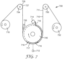
- the apparatus includes at least two rollers 752 and 718 (at least one of which is configured to convey an actinic radiation-transparent substrate 710) configured to convey an actinic radiation-transparent substrate 710 and an irradiation source 712 configured to direct actinic radiation through the actinic radiation-transparent substrate 710 at predetermined dosages at predetermined locations.
- the apparatus 700 further includes a means for depositing 714 a composition 716 onto a major surface 711 of the actinic radiation-transparent substrate 710 and a means for conveying 718 the actinic radiation-transparent substrate 710 or the irradiation source 712 with respect to each other.
- the actinic radiation-transparent substrate 710 is often a consumable material obtained separately from the apparatus 700 as opposed to being a component of the apparatus.
- the apparatus further includes a dam roller 745 comprising a pair of spaced apart edges (not shown) configured to contact the actinic radiation-transparent substrate 710 and define a containment area between the edges to provide space for the pool of composition 716 disposed on the actinic radiation-transparent substrate 710.
- the means for depositing 714 comprises a container configured to dispense the composition 716 as a thin layer onto a surface of the dam roller 745, which travels around the dam roller 745 and forms a pool on the major surface 711 of the substrate 710.
- a further means may be provided to contact the dam roller 745 with the actinic radiation-transparent substrate 710 to assist in minimizing leakage of the composition 716 off the actinic radiation-transparent substrate 710.
- such a means includes two tension rollers 754 and 756, wherein the actinic radiation-transparent substrate 710 is fed over one tension roller 756, under the dam roller 745, and over the other tension roller 754.
- This configuration allows the tension rollers 754 and 756 to be configured to apply force to the actinic radiation-transparent substrate 710 to maintain the substrate 710 in contact with the dam roller 745 as the actinic radiation-transparent substrate 710 is conveyed through the apparatus.
- the apparatus 700 operates similarly to the apparatus 500 of FIG. 5 described above, including that as the substrate 710 continues to be driven from an unwind roller 752 (as well as over the first tension roller 756, under the dam roller 745, and over the second tension roller 754) to the means for conveying 718 (e.g., a wind roller as shown in FIG. 7 ), an air knife 720 directs air towards the major surface 711 of the substrate 710 to assist in removing the composition 716 remaining on the major surface 711 of the substrate 710 that was not polymerized to form an adhesive by irradiation from the actinic irradiation source 712. The excess composition 716 is preferably returned to the containment area defined by the dam roller 745. Once a formed adhesive (e.g., the adhesive 727 and the adhesive 729) reaches the wind roller 718, the web of actinic radiation transparent substrate 710 is wound up.
- a formed adhesive e.g., the adhesive 727 and the adhesive 729
- the apparatus includes at least two rollers 852 and 818 (at least one of which is configured to convey an actinic radiation-transparent substrate 810) configured to convey an actinic radiation-transparent substrate 810 and an irradiation source 812 configured to direct actinic radiation through the actinic radiation-transparent substrate 810 at predetermined dosages at predetermined locations.
- the apparatus 800 further includes a means for depositing 814 a composition 816 onto a major surface 811 of the actinic radiation-transparent substrate 810 and a means for conveying 818 the actinic radiation-transparent substrate 810 or the irradiation source 812 with respect to each other.
- the actinic radiation-transparent substrate 810 is often a consumable material obtained separately from the apparatus 800 as opposed to being a component of the apparatus.
- the apparatus further includes a dam roller 845 comprising a pair of spaced apart edges (not shown) configured to contact the actinic radiation-transparent substrate 810 and define a containment area between the edges to provide space for the pool of composition 816 disposed on the actinic radiation-transparent substrate 810.
- the means for depositing 814 comprises a container configured to dispense the composition 816 as a thin layer onto a surface of the dam roller 845, which travels around the dam roller 845 and forms a pool on the major surface 811 of the substrate 810.
- a further means may be provided to contact the dam roller 845 with the actinic radiation-transparent substrate 810 to assist in minimizing leakage of the composition 816 off the actinic radiation-transparent substrate 810.
- such a means includes two tension rollers 854 and 856, wherein the actinic radiation-transparent substrate 810 is fed over one tension roller 856, under the dam roller 845, and over the other tension roller 854.
- This configuration allows the tension rollers 854 and 856 to be configured to apply force to the actinic radiation-transparent substrate 810 to maintain the substrate 810 in contact with the dam roller 845 as the actinic radiation-transparent substrate 810 is conveyed through the apparatus.
- FIG. 8 In the apparatus shown in FIG.
- the tension rollers are disposed adjacent to the dam roller 845 such that the actinic radiation-transparent substrate 810 is in contact with over 50 percent of the circumference of the dam roller 845 to further assist in minimizing leakage of the composition 816 off the actinic radiation-transparent substrate 810.
- the apparatus 800 operates similarly to the apparatus 500 of FIG. 5 described above, including that as the substrate 810 continues to be driven from an unwind roller 852 (as well as over the first tension roller 856, under the dam roller 845, and over the second tension roller 854) to the means for conveying 818 (e.g., a wind roller as shown in FIG. 8 ).
- the formed adhesive e.g., 827, 829 is irradiated by one or more second irradiation sources 832 to post-cure the adhesive prior to winding up the substrate 810.
- An air knife 820 optionally directs air towards the major surface 811 of the substrate 810 to assist in removing the composition 816 remaining on the major surface 811 of the substrate 810 that was not polymerized to form an adhesive by irradiation from the actinic irradiation source 812.
- the excess composition 816 is preferably returned to the containment area defined by the dam roller 845.
- the apparatus includes at least two rollers 952 and 918 (at least one of which is configured to convey an actinic radiation-transparent substrate 910), and an irradiation source 912 configured to direct actinic radiation through the actinic radiation-transparent substrate 910 at predetermined dosages at predetermined locations.
- the apparatus 900 further includes a means for depositing 914 a composition 916 onto a major surface 911 of the actinic radiation-transparent substrate 910 and a means for conveying 918 the actinic radiation-transparent substrate 910 or the irradiation source 912 with respect to each other.
- the means for depositing 914 comprises a die configured to dispense the composition 916 on the major surface 911 of the substrate 910.
- the composition 916 is preferably sufficiently viscous to remain on the major surface 911 of the substrate 910 without leaking off of the side edges of the substrate 910.
- the actinic radiation-transparent substrate 910 is often a consumable material obtained separately from the apparatus 900 as opposed to being a component of the apparatus.
- an air knife 920 configured to remove nonpolymerized composition 916 from the substrate 910 where one or more adhesives 917 and 919 are formed is provided with the apparatus 900.
- a further optional component of the apparatus 900 is a blade 960 that slices portions of the substrate 910 on which one or more adhesives (e.g., 927 and and/or 929) are disposed.
- a stack 961 of pieces of substrate 910 comprising one or more formed adhesives is illustrated.
- the substrate 910 on which one or more adhesives (e.g., 927 and/or 929) are formed are wound up on a wind roll (not shown).
- a die 914 deposits a composition 916 on a major surface 911 of an actinic radiation-transparent substrate 910.
- An irradiation source 912 directs radiation through the actinic radiation-transparent substrate 910 at one or more predetermined dosages at one or more predetermined locations.
- the composition 916 that has been irradiated at least partially polymerizes, forming at least one adhesive, such as the adhesive 917 and the adhesive 919, shown in FIG. 9 .
- the adhesive 917 comprises a variation in width as compared to the adhesive 919, as a result of the specific irradiation provided by the irradiation source 912.
- a means for conveying 918 the actinic radiation-transparent substrate 910 drives a web of the actinic radiation-transparent substrate 910 over a roller 952 to allow gravity to begin separating the composition 916 that was not polymerized to form an adhesive (e.g., 917 and 919).
- an air knife 920 directs air towards the major surface 911 of the substrate 910 to assist in removing the composition 916 remaining on the major surface 911 of the substrate 910.
- the excess composition 916 is preferably deposited in a container 958 for recycling or reuse.
- the blade 960 is employed and that portion of actinic radiation transparent substrate 910 is sliced off (and optionally added to a stack 961 of substrate 910 pieces each comprising at least one formed adhesive 927.
- the actinic radiation-transparent substrate comprises glass (e.g., in any of FIGS. 1-4 ) or a polymeric material (e.g., in any of FIGS. 1-9 ).
- the actinic radiation-transparent substrate comprises a polymeric material
- the substrate usually comprises a polymeric material selected from polyethylene terephthalate, polyethylene naphthalate, polycarbonate, polyimide, cycloolefin films, poly(methyl methacrylate), or combinations thereof.
- the actinic radiation-transparent substrate comprises glass
- the substrate usually comprises a glass selected from sodium borosilicate glass, soda-lime glass, and quartz glass.
- the substrate comprises a multilayer construction, for instance a polymeric sheet, an adhesive layer, and a liner.
- the multilayer construction comprises a coating (e.g., a release coating) upon which the integral adhesive is disposed.
- FIGS. 1-9 referred to a means for conveying an actinic radiation-transparent substrate or an irradiation source with respect to each other.
- the means for conveying generally includes mechanical means as known in the manufacturing arts, such as a motor, a servo motor, a stepper motor, or any combinations thereof.
- a motor ultimately drives one or more rollers, which convey a substrate (e.g., a cylinder or web of indefinite length) and/or the irradiation source.
- the actinic radiation is typically provided by an irradiation source that is a digital light projector (DLP) with a light emitting diode (LED), a DLP with a lamp, a laser scanning device with a laser, a liquid crystal display (LCD) panel with a backlight, a photomask with a lamp, or a photomask with an LED.
- a schematic is provided in FIG. 10 of a DLP with an LED or lamp
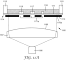
- schematics are provided in FIGS. 11a and 11b of a photomask with a lamp or LED
- a schematic is provided in FIG. 12 of an LCD panel with a backlight
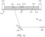
- a schematic is provided in FIG. 13 of a laser scanning device with a laser.
- an irradiation source 1000 for use in exemplary methods of the present disclosure, comprising a DLP 1065 with an LED or a lamp 1066 (1066 represents either an LED or a lamp).
- the DLP 1065 includes a plurality of individually movable reflectors, such as first reflector 1062, second reflector 1063, and third reflector 1064. Each reflector is positioned at a specific angle to direct irradiation from the LED or lamp 1066 towards a predetermined location of a composition 1016 disposed on a major surface 1011 of an actinic radiation-transparent substrate 1010.
- the intensity and duration of the irradiation from the LED or lamp 1066 will impact the depth of cure (e.g., polymerization) of the composition 1016 in a direction normal to the major surface 1011 of the substrate 1010 upon formation of one or more adhesives 1017 and 1019.
- one portion 1017b of integral adhesive 1017 has a greater thickness than another portion 1017a of the same integral adhesive 1017. This may be achieved by irradiating the portion 1017b with a greater dosage than the portion 1017a is irradiated.
- adhesive 1019 has a single thickness across its width due to receiving the same dosage across its width.
- DLPs are readily adjustable (e.g., using computer controls) to change the irradiation location and dosage and thereby the shape of the resulting formed adhesives, as needed without requiring a significant equipment alteration.
- DLPs are well-known in the art, for instance and without limitation, the apparatuses described in U.S. Patent Nos. 5,658,063 (Nasserbakht ), 5,905,545 (Poradish et al. ), 6,587,159 (Dewald ), 7,164,397 (Pettitt et al. ), 7,360,905 (Davis et al. ), 8,705,133 (Lieb et al.
- Suitable DLPs are commercially available, such as from Texas Instruments (Dallas, TX). As indicated above, either an LED or a lamp may be employed with a DLP. Suitable lamps may include a flash lamp, a low pressure mercury lamp, a medium pressure mercury lamp, and/or a microwave driven lamp. The skilled practitioner can select a suitable LED or lamp light source to provide the actinic radiation required to initiate polymerization for a particular polymerizable composition, for instance, the UV LED CBT-39-UV, available from Luminus Inc. (Sunnyvale, CA).
- an irradiation source 1100 comprising at least one photomask 1170a and 1170b with an LED or a lamp 1166 (1166 represents either an LED or a lamp), for use in exemplary methods of the present disclosure.
- a lens 1167 having a convex surface 1168 is employed with the LED or lamp 1166 to diffuse the irradiation across at least a portion of the one or more photomasks 1170a and 1170b. As shown in FIG.
- a first photomask 1170a is employed to direct irradiation from the LED or lamp 1166 towards a predetermined location of a composition 1116 disposed on a major surface 1111 of an actinic radiation-transparent substrate 1110.
- the intensity and duration of the irradiation from the LED or lamp 1166 will impact the depth of cure (e.g., polymerization) of the composition 1116 in a direction normal to the major surface 1111 of the substrate 1110 upon formation of one or more adhesives 1117 and 1119.
- one portion 1117b of integral adhesive 1117 has a greater thickness than another portion 1017a of the same integral adhesive 1117. This may be achieved by employing more than one photomask. For instance, referring to FIG.
- a photomask 1170a is shown in which a plurality of portions 1171a are provided through which irradiation can be directed to cure the composition 1116.
- a second photomask 1170b is shown in which one portion 1171b is provided through which irradiation can be directed to further cure the composition 1116.
- the portion 1117b has a greater thickness than the portion 1117a due to being irradiated twice; once using the first photomask 1170a and once using the second photomask 1170b; resulting in irradiation of the portion 1117b with a greater dosage than the portion 1117a.
- adhesive 1119 has a single thickness across its width due to receiving the same dosage across its width by exposure to irradiation through just the first photomask 1170a. While the photomasks in FIGS. 11a and 11b are shown as having opaque and transparent portions, the skilled practitioner will appreciate that photomasks including greyscale may be employed to achieve gradients in cure in different locations of the composition. Suitable photomasks are commercially available, for instance, NanoSculpt Photomasks from Infinite Graphics (Minneapolis, MN). Similar to using a DLP, either an LED or a lamp may be employed with a photomask.
- an irradiation source 1200 comprising a digital photomask 1272 (e.g., a LCD with a backlight 1266), wherein the backlight comprises an LED or a lamp 1266 (1266 represents either an LED or a lamp), for use in exemplary methods of the present disclosure.
- a lens 1267 having a convex surface 1268 is employed with the backlight 1266 to diffuse the irradiation across at least a portion of the digital photomask 1272.
- the intensity and duration of the irradiation from the backlight 1266 will impact the depth of cure (e.g., polymerization) of the composition 1216 in a direction normal to the major surface 1211 of the substrate 1210 upon formation of one or more adhesives 1217 and 1219.
- one portion 1217b of integral adhesive 1217 has a greater thickness than another portion 1217a of the same integral adhesive 1217. This may be achieved by irradiating the portion 1217b with a greater dosage than the portion 1217a is irradiated.
- adhesive 1219 has a single thickness across its width due to receiving the same dosage across its width.
- a benefit of employing a digital photomask is that the individual pixels are readily adjustable (e.g., using computer controls) to change the irradiation location and dosage and thereby the shape of the resulting formed adhesives, as needed without requiring a significant equipment alteration.
- Suitable LCDs are commercially available, for instance, the LCD LQ043T1DG28, available from Sharp Corporation (Osaka, Japan).
- an irradiation source 1300 comprising a laser scanning device 1362 with a laser 1366, for use in exemplary methods of the present disclosure.
- the laser scanning device 1362 includes at least one individually movable mirror. Each mirror is positioned at a specific angle to direct irradiation from the laser 1366 towards a predetermined location of a composition 1316 disposed on a major surface 1311 of an actinic radiation-transparent substrate 1310.
- the intensity and duration of the irradiation from the laser 1366 will impact the depth of cure (e.g., polymerization) of the composition 1316 in a direction normal to the major surface 1311 of the substrate 1310 upon formation of one or more adhesives 1317 and 1319.
- one portion 1317b of integral adhesive 1317 has a greater thickness than another portion 1317a of the same integral adhesive 1317. This may be achieved by irradiating the portion 1317b with a greater dosage than the portion 1317a is irradiated.
- adhesive 1319 has a single thickness across its width due to receiving the same dosage across its width.
- Suitable laser scanning devices are commercially available, such as the JS2808 Galvanometer Scanner from Sino-Galvo (Beijing) Technology Co., LTD. (Beijing, China).
- the skilled practitioner can select a suitable laser to provide the actinic radiation required to initiate polymerization for a particular polymerizable composition, for instance, the CUBE 405-100C Diode Laser System from Coherent Inc. (Santa Clara, CA).
- any of the above irradiation sources of the present disclosure are suitable for use in each of the apparatuses of the disclosed embodiments herein. It is an advantage of these irradiation sources that they are readily configured to provide one or more predetermined dosages of irradiation at one or more predetermined locations, allowing the manufacture of adhesives having variations in size and shape, particularly in thickness normal to a substrate.
- Table 1 provides a role and a source for materials used in the Examples below: Table 1.
- Materials Function Abbreviation Description Source Monomer 1 iOA IsoOctyl Acrylate 3M, St Paul, MN Monomer 2 AA Acrylic Acid Sigma-Aldrich, St Louis, MO Monomer 3 iBOA IsoBornyl Acrylate OSAKA Organic Chemical Industry LTD, Osaka, Japan Crosslinker1 HDDA 1,6-Hexanedioldiacrylate Sartomer Americas, Exton, PA Initiator 1 IRGACURE TPO 2, 4, 6-trimethylbenzoyldiphenylphosphine oxide BASF Corporation, Florham Park, NJ Inhibitor BHT 2,6 Di-tert-butyl-4-methylphenol Sigma-Aldrich, St Louis, MO Absorption Modifier TINOPAL OB CO Benzoxazole, 2,2'-(2,5-
- the actinic radiation transparent substrate 10 was constructed from an Optically Clear Cast Acrylic Tube, 8 inches (20.32 centimeters (cm)) outer diameter x 7-3/4 inches (19.7 cm) inner diameter, cut to a length of 6 inches (15.24 cm), obtained as item 8486K735 from McMaster-Carr, Chicago, IL, which was wrapped with a clear PET silicone release liner, type RF12N in 5 mil (127 micrometer) thickness, available from SKC Haas, Seoul, Korea. Thus the siliconized side of the release liner formed the major surface 11 of the actinic radiation transparent substrate 10.
- a 10 mm hole was drilled at the center of the steel tube, and 2 LEDs (One LED emitting 390 nm UV light, model UV3TZ-390-15, and one LED emitting 405 nm UV light, model UV3TZ-405-15, both available from Bivar Inc, Irvine, CA) with 40 cm cable leads and a 82 ohm resistor were inserted through the hole and mounted to the stationary hollow steel tube with help of small acrylic bars.
- the LEDs were facing downwards inside of the Clear Cast Acrylic Tube, with about 5 mm distance from the inner surface of the tube.
- the DC Motor and the 2 LEDs were connected to an iPad and the 2 LEDs to an iPad R3 microcontroller with iPad Shield, available from SparkFun Electronics, Niwot, CO.
- the microcontroller was programmed to rotate the Clear Cast Acrylic Tube approximately 30 degrees, then to stop and light up the LEDs for 2 seconds, the program was set to repeat this sequence for a total of 10 times.
- a container 16 with the base plate dimension of 6.5 inches (16.51 cm) by 4.5 inches (11.43 cm) and 0.5 inch (1.27 cm) tall side walls was constructed from Optically Fluorescent Cast Acrylic, 3/32" Thick, Amber, available as 85635K471 from McMaster-Carr, Chicago, IL, and placed on a lab jack under the Clear Cast Acrylic Tube.
- a UV Intensity Analyzer Model 356, from OAI Instruments, San Jose, CA, was used to measure the intensity and energy of the LEDs at the major surface 11.
- the 400 nm broad band sensor was attached to the Analyzer, and the sensor surface was centered under the LED, with the sensor housing touching the major surface 11.
- For the 390 nm LED an intensity of 39.3 mW/cm 2 and an energy dosage of 79.1 mJ/cm 2 was measured for the 2 second illumination.
- For the 405 nm LED an intensity of 31.3 mW/cm 2 and an energy dosage of 63.7 mJ/cm 2 was measured for the 2 second illumination.
- An actinic radiation polymerizable composition was prepared by charging a 100 ml amber glass jar with 6.25 g AA, 21.9 g iOA and 21.9 g iBOA, 0.156 g HDDA, 0.05 g TINOPAL OB CO, 0.05 g BHT and 0.75 g IRGACURE TPO.
- the jar was sealed and rotated on a laboratory bench top roller MX-T6-S at approximately 10 RPM for 2 hours.
- the composition was poured into the container 16 of the experimental apparatus and the container was lifted with help of the lab jack, so that the composition contacted the major surface 11 right underneath the LEDs.
- the experimental apparatus was switched on and went through the sequence of rotating the drum and switching on the LEDs.
- a microscopy glass slide was pressed onto the dots, and it was observed that they adhered to the glass slide.
- the dots then were post cured for 10 minutes in an Asiga Flash UV post cure chamber, available from Asiga, Anaheim Hills, California, USA.
- This post cure chamber contains four 9W fluorescent bulbs with a peak wavelength of 365 nm, arranged approximately 2 inches (5.08 cm) from a 5.5 inch (13.97 cm) by 5.75 inch (14.61 cm) base plate.
- the UV intensity was measured using the UV Intensity Analyzer, Model 356, from OAI Instruments, San Jose, CA, with the 400 nm broad band sensor. A UV intensity of approximately 5.3 mW/cm 2 was found throughout the base plate.
Landscapes
- Chemical & Material Sciences (AREA)
- Engineering & Computer Science (AREA)
- Physics & Mathematics (AREA)
- Materials Engineering (AREA)
- Optics & Photonics (AREA)
- Manufacturing & Machinery (AREA)
- Organic Chemistry (AREA)
- Mechanical Engineering (AREA)
- Plasma & Fusion (AREA)
- Chemical Kinetics & Catalysis (AREA)
- Adhesives Or Adhesive Processes (AREA)
- Adhesive Tapes (AREA)
Applications Claiming Priority (2)
| Application Number | Priority Date | Filing Date | Title |
|---|---|---|---|
| US201562272463P | 2015-12-29 | 2015-12-29 | |
| PCT/US2016/066275 WO2017116678A1 (en) | 2015-12-29 | 2016-12-13 | Continuous additive manufacturing methods |
Publications (3)
| Publication Number | Publication Date |
|---|---|
| EP3397399A1 EP3397399A1 (en) | 2018-11-07 |
| EP3397399A4 EP3397399A4 (en) | 2019-08-14 |
| EP3397399B1 true EP3397399B1 (en) | 2025-06-04 |
Family
ID=59225783
Family Applications (1)
| Application Number | Title | Priority Date | Filing Date |
|---|---|---|---|
| EP16882299.7A Active EP3397399B1 (en) | 2015-12-29 | 2016-12-13 | Continuous additive manufacturing methods |
Country Status (8)
| Country | Link |
|---|---|
| US (1) | US11597856B2 (enExample) |
| EP (1) | EP3397399B1 (enExample) |
| JP (1) | JP6952039B2 (enExample) |
| KR (1) | KR102643787B1 (enExample) |
| CN (1) | CN108430649A (enExample) |
| BR (1) | BR112018013443A2 (enExample) |
| TW (1) | TW201730306A (enExample) |
| WO (1) | WO2017116678A1 (enExample) |
Families Citing this family (10)
| Publication number | Priority date | Publication date | Assignee | Title |
|---|---|---|---|---|
| KR102655948B1 (ko) | 2015-12-29 | 2024-04-09 | 쓰리엠 이노베이티브 프로퍼티즈 캄파니 | 접착제를 위한 적층 제조 방법 및 접착 물품 |
| BR112018013510A2 (pt) | 2015-12-29 | 2018-12-11 | 3M Innovative Properties Co | aparelho de fabricação de aditivo contínuo |
| US11179886B2 (en) | 2016-01-21 | 2021-11-23 | 3M Innovative Properties Company | Additive processing of fluoropolymers |
| DE102017213072B4 (de) * | 2016-09-05 | 2024-11-14 | Ford Global Technologies, Llc | Additives Fertigungsverfahren |
| US10937572B2 (en) * | 2018-04-06 | 2021-03-02 | Abb Power Grids Switzerland Ag | Apparatus and method for forming an article |
| WO2020106808A1 (en) * | 2018-11-20 | 2020-05-28 | Avery Dennison Retail Information Services, Llc | Digitally produced label for transfer using selective laser sintering (sls) methods |
| NL2022394B1 (en) * | 2019-01-14 | 2020-08-14 | Xeikon Prepress Nv | Apparatus and method for genrating a relief carrier |
| AU2019422692B2 (en) * | 2019-01-15 | 2025-01-30 | Sicpa Holding Sa | Process for producing optical effect layers |
| NL2023079B1 (en) * | 2019-05-06 | 2020-11-30 | Xeikon Prepress Nv | Apparatus and method for generating a 3d structure |
| TWI748872B (zh) | 2021-02-19 | 2021-12-01 | 歆熾電氣技術股份有限公司 | 薄膜圖案及其形成方法 |
Family Cites Families (50)
| Publication number | Priority date | Publication date | Assignee | Title |
|---|---|---|---|---|
| US2797201A (en) | 1953-05-11 | 1957-06-25 | Standard Oil Co | Process of producing hollow particles and resulting product |
| US3365315A (en) | 1963-08-23 | 1968-01-23 | Minnesota Mining & Mfg | Glass bubbles prepared by reheating solid glass partiles |
| US4330590A (en) | 1980-02-14 | 1982-05-18 | Minnesota Mining And Manufacturing Company | Photoactive mixture of acrylic monomers and chromophore-substituted halomethyl-2-triazine |
| US4329384A (en) | 1980-02-14 | 1982-05-11 | Minnesota Mining And Manufacturing Company | Pressure-sensitive adhesive tape produced from photoactive mixture of acrylic monomers and polynuclear-chromophore-substituted halomethyl-2-triazine |
| EP0228671A1 (en) * | 1985-12-23 | 1987-07-15 | General Electric Company | Method for the production of a coated substrate with controlled surface characteristics |
| US4950696A (en) | 1987-08-28 | 1990-08-21 | Minnesota Mining And Manufacturing Company | Energy-induced dual curable compositions |
| US6436532B1 (en) * | 1991-02-28 | 2002-08-20 | 3M Innovative Properties Company | Multi-stage irradiation process for production of acrylic based adhesives and adhesives made thereby |
| WO1992015651A1 (en) | 1991-02-28 | 1992-09-17 | Minnesota Mining And Manufacturing Company | Multi-stage irradiation process for production of acrylic based adhesives and adhesives made thereby |
| AU682853B2 (en) | 1993-03-22 | 1997-10-23 | Minnesota Mining And Manufacturing Company | Windowless frame delivered dressing and method of manufacture |
| US5591527A (en) | 1994-11-02 | 1997-01-07 | Minnesota Mining And Manufacturing Company | Optical security articles and methods for making same |
| US5905545A (en) | 1995-01-27 | 1999-05-18 | Texas Instruments Incorporated | Full-color projection display system using two light modulators |
| US20010028953A1 (en) | 1998-11-16 | 2001-10-11 | 3M Innovative Properties Company | Adhesive compositions and methods of use |
| US5658063A (en) | 1995-11-02 | 1997-08-19 | Texas Instruments Incorporated | Monitorless video projection system |
| US5766277A (en) * | 1996-09-20 | 1998-06-16 | Minnesota Mining And Manufacturing Company | Coated abrasive article and method of making same |
| DE19819304B4 (de) * | 1998-04-30 | 2006-05-18 | Institut für Holztechnologie Dresden gGmbH | Verfahren und Vorrichtung zur Trockenlackierung großporiger Substrate |
| US6587159B1 (en) | 1998-05-29 | 2003-07-01 | Texas Instruments Incorporated | Projector for digital cinema |
| DE19905934A1 (de) * | 1999-02-12 | 2000-08-17 | Beiersdorf Ag | Verfahren zur Herstellung einer Beschichtung von lösungsmittelfreien Haftklebesystemen auf insbesondere releasebeschichteten Substraten in Verbindung mit einer Vernetzung des Haftklebesystems |
| US6455152B1 (en) * | 1999-08-31 | 2002-09-24 | 3M Innovative Properties Company | Adhesive coating method and adhesive coated article |
| DE10008844A1 (de) | 2000-02-25 | 2001-09-06 | Beiersdorf Ag | Verfahren zur Vernetzung von Polyacrylaten durch Elektronenstrahlen |
| DE10014563A1 (de) * | 2000-03-23 | 2001-10-04 | Beiersdorf Ag | Elektronenstrahl-Vernetzung von Haftklebemassen |
| JP2004300333A (ja) | 2003-03-31 | 2004-10-28 | Lintec Corp | 易剥離性粘着シート、その製造法及び使用方法 |
| US7070406B2 (en) | 2003-04-29 | 2006-07-04 | Hewlett-Packard Development Company, L.P. | Apparatus for embossing a flexible substrate with a pattern carried by an optically transparent compliant media |
| US7164397B2 (en) | 2003-09-30 | 2007-01-16 | Texas Instruments Incorporated | Discrete light color processor |
| TW200710570A (en) | 2005-05-31 | 2007-03-16 | Taiyo Ink Mfg Co Ltd | Composition for forming adhesive pattern, multilayer structure obtained by using same, and method for producing such multilayer structure |
| US7360905B2 (en) | 2005-06-24 | 2008-04-22 | Texas Instruments Incorporated | Compact optical engine for very small personal projectors using LED illumination |
| US20070031791A1 (en) | 2005-08-03 | 2007-02-08 | 3M Innovative Properties Company | Scanning models for digital orthodontics |
| US8542408B2 (en) | 2006-12-29 | 2013-09-24 | Texas Instruments Incorporated | High dynamic range display systems |
| DE102007022726A1 (de) | 2007-05-11 | 2008-11-13 | Tesa Ag | Verfahren und Vorrichtung zur lösungsmittelfreien Herstellung von Acrylathaftklebemassen |
| KR20110036749A (ko) | 2008-08-27 | 2011-04-08 | 히다치 가세고교 가부시끼가이샤 | 감광성 접착제 조성물, 및 그것을 이용한 필름상 접착제, 접착 시트, 접착제 패턴, 접착제층 부착 반도체 웨이퍼 및 반도체 장치 |
| WO2010027507A2 (en) * | 2008-09-08 | 2010-03-11 | Eastman Chemical Company | Washable psa laminates |
| JP2010080680A (ja) | 2008-09-26 | 2010-04-08 | Bridgestone Corp | 凹凸パターンの形成方法及び凹凸パターンの製造装置 |
| JP2010077317A (ja) | 2008-09-26 | 2010-04-08 | Three M Innovative Properties Co | 接着剤組成物、接着フィルム及びその使用方法 |
| JPWO2010122942A1 (ja) * | 2009-04-21 | 2012-10-25 | 日東電工株式会社 | 加熱膨張型再剥離性アクリル系粘着テープ又はシート |
| KR101190855B1 (ko) | 2010-07-01 | 2012-10-15 | 도레이첨단소재 주식회사 | 불균일 점착력을 가지는 점착테이프와 그 제조 장치 및 제조 방법 |
| CN103140299B (zh) * | 2010-10-15 | 2016-08-10 | 3M创新有限公司 | 有机硅的紫外线辐射交联 |
| KR101813260B1 (ko) | 2011-01-14 | 2018-01-02 | 삼성전자주식회사 | 패턴형성 가능한 접착 조성물, 이를 이용한 반도체 패키지, 및 이의 제조방법 |
| KR20140033173A (ko) * | 2011-05-31 | 2014-03-17 | 쓰리엠 이노베이티브 프로퍼티즈 캄파니 | 상이하게 패턴 경화된 미세구조화 용품을 제조하는 방법 |
| JP2013047321A (ja) * | 2011-07-28 | 2013-03-07 | Nitto Denko Corp | 粘着シート |
| JP5823786B2 (ja) | 2011-09-12 | 2015-11-25 | 日東電工株式会社 | 光反応生成物シートの製造方法およびその装置 |
| US8820944B2 (en) | 2011-10-25 | 2014-09-02 | Texas Instruments Incorporated | Selectable throw ratio image projection device |
| JP2013186140A (ja) | 2012-03-05 | 2013-09-19 | Sumitomo Bakelite Co Ltd | 光導波路の製造方法、光導波路の製造装置および光導波路 |
| US10717260B2 (en) * | 2012-07-05 | 2020-07-21 | Sony Corporation | Manufacturing method of laminated structure, laminated structure and electronic device |
| JP2014056040A (ja) | 2012-09-11 | 2014-03-27 | Sumitomo Chemical Co Ltd | 偏光板の製造方法および製造装置 |
| EP2803712A1 (en) | 2013-05-17 | 2014-11-19 | 3M Innovative Properties Company | Multilayer Pressure Sensitive Adhesive Assembly |
| JP6147105B2 (ja) | 2013-06-10 | 2017-06-14 | ニッタ株式会社 | 感温性粘着シート、感温性粘着テープおよび粘着シート形成方法 |
| CN106103620A (zh) * | 2014-01-08 | 2016-11-09 | 艾利丹尼森公司 | 使用选择性脱黏的黏合剂的制品、组合物、系统和方法 |
| WO2015122479A1 (ja) * | 2014-02-14 | 2015-08-20 | 富士フイルム株式会社 | 輝度向上フィルム、光学シート部材および液晶表示装置 |
| KR101757404B1 (ko) * | 2015-07-24 | 2017-07-12 | 한국기계연구원 | 점착력 제어 필름 기반 선택적 연속 전사 장치 |
| KR102655948B1 (ko) | 2015-12-29 | 2024-04-09 | 쓰리엠 이노베이티브 프로퍼티즈 캄파니 | 접착제를 위한 적층 제조 방법 및 접착 물품 |
| BR112018013510A2 (pt) | 2015-12-29 | 2018-12-11 | 3M Innovative Properties Co | aparelho de fabricação de aditivo contínuo |
-
2016
- 2016-12-13 CN CN201680077797.2A patent/CN108430649A/zh active Pending
- 2016-12-13 BR BR112018013443A patent/BR112018013443A2/pt not_active Application Discontinuation
- 2016-12-13 JP JP2018534072A patent/JP6952039B2/ja active Active
- 2016-12-13 WO PCT/US2016/066275 patent/WO2017116678A1/en not_active Ceased
- 2016-12-13 EP EP16882299.7A patent/EP3397399B1/en active Active
- 2016-12-13 US US16/066,360 patent/US11597856B2/en active Active
- 2016-12-13 KR KR1020187021474A patent/KR102643787B1/ko active Active
- 2016-12-28 TW TW105143488A patent/TW201730306A/zh unknown
Also Published As
| Publication number | Publication date |
|---|---|
| US20180355221A1 (en) | 2018-12-13 |
| CN108430649A (zh) | 2018-08-21 |
| JP2019510836A (ja) | 2019-04-18 |
| BR112018013443A2 (pt) | 2018-12-04 |
| US11597856B2 (en) | 2023-03-07 |
| EP3397399A4 (en) | 2019-08-14 |
| WO2017116678A1 (en) | 2017-07-06 |
| JP6952039B2 (ja) | 2021-10-20 |
| TW201730306A (zh) | 2017-09-01 |
| EP3397399A1 (en) | 2018-11-07 |
| KR20180099772A (ko) | 2018-09-05 |
| KR102643787B1 (ko) | 2024-03-06 |
Similar Documents
| Publication | Publication Date | Title |
|---|---|---|
| EP3397399B1 (en) | Continuous additive manufacturing methods | |
| EP3397445B1 (en) | Continuous additive manufacturing apparatus | |
| EP3397712B1 (en) | Additive manufacturing methods for adhesives and adhesive articles | |
| US9796803B2 (en) | Under layer film-forming composition for imprints and method of forming pattern | |
| CN110831735B (zh) | 用于粘合剂和粘合剂制品的增材制造方法 | |
| KR101400554B1 (ko) | 양면 점착 테이프 | |
| TWI821421B (zh) | 薄膜製造方法及設備、薄膜 | |
| JP6753038B2 (ja) | 光硬化性組成物 | |
| JPH07330815A (ja) | 光重合方法及びこの反応に用いる光重合装置 | |
| JP2005324346A (ja) | 成形品の製造方法 | |
| TWI767917B (zh) | 用於黏著劑之積層製造方法及黏著劑物品 |
Legal Events
| Date | Code | Title | Description |
|---|---|---|---|
| STAA | Information on the status of an ep patent application or granted ep patent |
Free format text: STATUS: THE INTERNATIONAL PUBLICATION HAS BEEN MADE |
|
| PUAI | Public reference made under article 153(3) epc to a published international application that has entered the european phase |
Free format text: ORIGINAL CODE: 0009012 |
|
| STAA | Information on the status of an ep patent application or granted ep patent |
Free format text: STATUS: REQUEST FOR EXAMINATION WAS MADE |
|
| 17P | Request for examination filed |
Effective date: 20180626 |
|
| AK | Designated contracting states |
Kind code of ref document: A1 Designated state(s): AL AT BE BG CH CY CZ DE DK EE ES FI FR GB GR HR HU IE IS IT LI LT LU LV MC MK MT NL NO PL PT RO RS SE SI SK SM TR |
|
| AX | Request for extension of the european patent |
Extension state: BA ME |
|
| DAV | Request for validation of the european patent (deleted) | ||
| DAX | Request for extension of the european patent (deleted) | ||
| A4 | Supplementary search report drawn up and despatched |
Effective date: 20190716 |
|
| RIC1 | Information provided on ipc code assigned before grant |
Ipc: C09J 7/20 20180101ALI20190710BHEP Ipc: C09J 5/00 20060101AFI20190710BHEP Ipc: B05D 3/06 20060101ALI20190710BHEP Ipc: B29C 64/00 20170101ALI20190710BHEP Ipc: B05D 1/28 20060101ALI20190710BHEP |
|
| STAA | Information on the status of an ep patent application or granted ep patent |
Free format text: STATUS: EXAMINATION IS IN PROGRESS |
|
| 17Q | First examination report despatched |
Effective date: 20220912 |
|
| REG | Reference to a national code |
Ref country code: DE Ref legal event code: R079 Free format text: PREVIOUS MAIN CLASS: B05D0003020000 Ipc: C09J0005000000 Ref country code: DE Ref legal event code: R079 Ref document number: 602016092493 Country of ref document: DE Free format text: PREVIOUS MAIN CLASS: B05D0003020000 Ipc: C09J0005000000 |
|
| GRAP | Despatch of communication of intention to grant a patent |
Free format text: ORIGINAL CODE: EPIDOSNIGR1 |
|
| STAA | Information on the status of an ep patent application or granted ep patent |
Free format text: STATUS: GRANT OF PATENT IS INTENDED |
|
| RIC1 | Information provided on ipc code assigned before grant |
Ipc: B33Y 70/00 20150101ALI20250117BHEP Ipc: B05D 1/28 20060101ALI20250117BHEP Ipc: B05D 3/06 20060101ALI20250117BHEP Ipc: C09J 7/20 20180101ALI20250117BHEP Ipc: B29C 64/00 20170101ALI20250117BHEP Ipc: C09J 5/00 20060101AFI20250117BHEP |
|
| INTG | Intention to grant announced |
Effective date: 20250206 |
|
| P01 | Opt-out of the competence of the unified patent court (upc) registered |
Free format text: CASE NUMBER: APP_8093/2025 Effective date: 20250218 |
|
| GRAS | Grant fee paid |
Free format text: ORIGINAL CODE: EPIDOSNIGR3 |
|
| GRAA | (expected) grant |
Free format text: ORIGINAL CODE: 0009210 |
|
| STAA | Information on the status of an ep patent application or granted ep patent |
Free format text: STATUS: THE PATENT HAS BEEN GRANTED |
|
| AK | Designated contracting states |
Kind code of ref document: B1 Designated state(s): AL AT BE BG CH CY CZ DE DK EE ES FI FR GB GR HR HU IE IS IT LI LT LU LV MC MK MT NL NO PL PT RO RS SE SI SK SM TR |
|
| REG | Reference to a national code |
Ref country code: GB Ref legal event code: FG4D |
|
| REG | Reference to a national code |
Ref country code: CH Ref legal event code: EP |
|
| REG | Reference to a national code |
Ref country code: DE Ref legal event code: R096 Ref document number: 602016092493 Country of ref document: DE |
|
| REG | Reference to a national code |
Ref country code: IE Ref legal event code: FG4D |
|
| REG | Reference to a national code |
Ref country code: NL Ref legal event code: MP Effective date: 20250604 |
|
| PG25 | Lapsed in a contracting state [announced via postgrant information from national office to epo] |
Ref country code: ES Free format text: LAPSE BECAUSE OF FAILURE TO SUBMIT A TRANSLATION OF THE DESCRIPTION OR TO PAY THE FEE WITHIN THE PRESCRIBED TIME-LIMIT Effective date: 20250604 Ref country code: FI Free format text: LAPSE BECAUSE OF FAILURE TO SUBMIT A TRANSLATION OF THE DESCRIPTION OR TO PAY THE FEE WITHIN THE PRESCRIBED TIME-LIMIT Effective date: 20250604 |
|
| REG | Reference to a national code |
Ref country code: LT Ref legal event code: MG9D |
|
| PG25 | Lapsed in a contracting state [announced via postgrant information from national office to epo] |
Ref country code: NO Free format text: LAPSE BECAUSE OF FAILURE TO SUBMIT A TRANSLATION OF THE DESCRIPTION OR TO PAY THE FEE WITHIN THE PRESCRIBED TIME-LIMIT Effective date: 20250904 Ref country code: GR Free format text: LAPSE BECAUSE OF FAILURE TO SUBMIT A TRANSLATION OF THE DESCRIPTION OR TO PAY THE FEE WITHIN THE PRESCRIBED TIME-LIMIT Effective date: 20250905 |
|
| PG25 | Lapsed in a contracting state [announced via postgrant information from national office to epo] |
Ref country code: PL Free format text: LAPSE BECAUSE OF FAILURE TO SUBMIT A TRANSLATION OF THE DESCRIPTION OR TO PAY THE FEE WITHIN THE PRESCRIBED TIME-LIMIT Effective date: 20250604 |
|
| PG25 | Lapsed in a contracting state [announced via postgrant information from national office to epo] |
Ref country code: BG Free format text: LAPSE BECAUSE OF FAILURE TO SUBMIT A TRANSLATION OF THE DESCRIPTION OR TO PAY THE FEE WITHIN THE PRESCRIBED TIME-LIMIT Effective date: 20250604 |
|
| PG25 | Lapsed in a contracting state [announced via postgrant information from national office to epo] |
Ref country code: HR Free format text: LAPSE BECAUSE OF FAILURE TO SUBMIT A TRANSLATION OF THE DESCRIPTION OR TO PAY THE FEE WITHIN THE PRESCRIBED TIME-LIMIT Effective date: 20250604 |
|
| PG25 | Lapsed in a contracting state [announced via postgrant information from national office to epo] |
Ref country code: RS Free format text: LAPSE BECAUSE OF FAILURE TO SUBMIT A TRANSLATION OF THE DESCRIPTION OR TO PAY THE FEE WITHIN THE PRESCRIBED TIME-LIMIT Effective date: 20250904 |
|
| PG25 | Lapsed in a contracting state [announced via postgrant information from national office to epo] |
Ref country code: LV Free format text: LAPSE BECAUSE OF FAILURE TO SUBMIT A TRANSLATION OF THE DESCRIPTION OR TO PAY THE FEE WITHIN THE PRESCRIBED TIME-LIMIT Effective date: 20250604 |
|
| PG25 | Lapsed in a contracting state [announced via postgrant information from national office to epo] |
Ref country code: NL Free format text: LAPSE BECAUSE OF FAILURE TO SUBMIT A TRANSLATION OF THE DESCRIPTION OR TO PAY THE FEE WITHIN THE PRESCRIBED TIME-LIMIT Effective date: 20250604 |
|
| PG25 | Lapsed in a contracting state [announced via postgrant information from national office to epo] |
Ref country code: PT Free format text: LAPSE BECAUSE OF FAILURE TO SUBMIT A TRANSLATION OF THE DESCRIPTION OR TO PAY THE FEE WITHIN THE PRESCRIBED TIME-LIMIT Effective date: 20251006 |
|
| REG | Reference to a national code |
Ref country code: AT Ref legal event code: MK05 Ref document number: 1800341 Country of ref document: AT Kind code of ref document: T Effective date: 20250604 |
|
| PG25 | Lapsed in a contracting state [announced via postgrant information from national office to epo] |
Ref country code: IS Free format text: LAPSE BECAUSE OF FAILURE TO SUBMIT A TRANSLATION OF THE DESCRIPTION OR TO PAY THE FEE WITHIN THE PRESCRIBED TIME-LIMIT Effective date: 20251004 |
|
| PGFP | Annual fee paid to national office [announced via postgrant information from national office to epo] |
Ref country code: DE Payment date: 20251126 Year of fee payment: 10 |
|
| PG25 | Lapsed in a contracting state [announced via postgrant information from national office to epo] |
Ref country code: AT Free format text: LAPSE BECAUSE OF FAILURE TO SUBMIT A TRANSLATION OF THE DESCRIPTION OR TO PAY THE FEE WITHIN THE PRESCRIBED TIME-LIMIT Effective date: 20250604 Ref country code: SM Free format text: LAPSE BECAUSE OF FAILURE TO SUBMIT A TRANSLATION OF THE DESCRIPTION OR TO PAY THE FEE WITHIN THE PRESCRIBED TIME-LIMIT Effective date: 20250604 |
|
| PG25 | Lapsed in a contracting state [announced via postgrant information from national office to epo] |
Ref country code: CZ Free format text: LAPSE BECAUSE OF FAILURE TO SUBMIT A TRANSLATION OF THE DESCRIPTION OR TO PAY THE FEE WITHIN THE PRESCRIBED TIME-LIMIT Effective date: 20250604 |
|
| PG25 | Lapsed in a contracting state [announced via postgrant information from national office to epo] |
Ref country code: EE Free format text: LAPSE BECAUSE OF FAILURE TO SUBMIT A TRANSLATION OF THE DESCRIPTION OR TO PAY THE FEE WITHIN THE PRESCRIBED TIME-LIMIT Effective date: 20250604 |
|
| PG25 | Lapsed in a contracting state [announced via postgrant information from national office to epo] |
Ref country code: SK Free format text: LAPSE BECAUSE OF FAILURE TO SUBMIT A TRANSLATION OF THE DESCRIPTION OR TO PAY THE FEE WITHIN THE PRESCRIBED TIME-LIMIT Effective date: 20250604 Ref country code: RO Free format text: LAPSE BECAUSE OF FAILURE TO SUBMIT A TRANSLATION OF THE DESCRIPTION OR TO PAY THE FEE WITHIN THE PRESCRIBED TIME-LIMIT Effective date: 20250604 |
|
| PG25 | Lapsed in a contracting state [announced via postgrant information from national office to epo] |
Ref country code: IT Free format text: LAPSE BECAUSE OF FAILURE TO SUBMIT A TRANSLATION OF THE DESCRIPTION OR TO PAY THE FEE WITHIN THE PRESCRIBED TIME-LIMIT Effective date: 20250604 |
|
| REG | Reference to a national code |
Ref country code: DE Ref legal event code: R097 Ref document number: 602016092493 Country of ref document: DE |
|
| PLBE | No opposition filed within time limit |
Free format text: ORIGINAL CODE: 0009261 |
|
| STAA | Information on the status of an ep patent application or granted ep patent |
Free format text: STATUS: NO OPPOSITION FILED WITHIN TIME LIMIT |
|
| PG25 | Lapsed in a contracting state [announced via postgrant information from national office to epo] |
Ref country code: DK Free format text: LAPSE BECAUSE OF FAILURE TO SUBMIT A TRANSLATION OF THE DESCRIPTION OR TO PAY THE FEE WITHIN THE PRESCRIBED TIME-LIMIT Effective date: 20250604 |
|
| REG | Reference to a national code |
Ref country code: CH Ref legal event code: L10 Free format text: ST27 STATUS EVENT CODE: U-0-0-L10-L00 (AS PROVIDED BY THE NATIONAL OFFICE) Effective date: 20260416 |