EP3397178B1 - Intraprozedurale embolieschutzvorrichtung mit mehrfachzugang - Google Patents
Intraprozedurale embolieschutzvorrichtung mit mehrfachzugang Download PDFInfo
- Publication number
- EP3397178B1 EP3397178B1 EP16882367.2A EP16882367A EP3397178B1 EP 3397178 B1 EP3397178 B1 EP 3397178B1 EP 16882367 A EP16882367 A EP 16882367A EP 3397178 B1 EP3397178 B1 EP 3397178B1
- Authority
- EP
- European Patent Office
- Prior art keywords
- filter body
- port
- catheter
- porous mesh
- embolic protection
- Prior art date
- Legal status (The legal status is an assumption and is not a legal conclusion. Google has not performed a legal analysis and makes no representation as to the accuracy of the status listed.)
- Active
Links
Images


Classifications
-
- A—HUMAN NECESSITIES
- A61—MEDICAL OR VETERINARY SCIENCE; HYGIENE
- A61F—FILTERS IMPLANTABLE INTO BLOOD VESSELS; PROSTHESES; DEVICES PROVIDING PATENCY TO, OR PREVENTING COLLAPSING OF, TUBULAR STRUCTURES OF THE BODY, e.g. STENTS; ORTHOPAEDIC, NURSING OR CONTRACEPTIVE DEVICES; FOMENTATION; TREATMENT OR PROTECTION OF EYES OR EARS; BANDAGES, DRESSINGS OR ABSORBENT PADS; FIRST-AID KITS
- A61F2/00—Filters implantable into blood vessels; Prostheses, i.e. artificial substitutes or replacements for parts of the body; Appliances for connecting them with the body; Devices providing patency to, or preventing collapsing of, tubular structures of the body, e.g. stents
- A61F2/01—Filters implantable into blood vessels
- A61F2/011—Instruments for their placement or removal
-
- A—HUMAN NECESSITIES
- A61—MEDICAL OR VETERINARY SCIENCE; HYGIENE
- A61F—FILTERS IMPLANTABLE INTO BLOOD VESSELS; PROSTHESES; DEVICES PROVIDING PATENCY TO, OR PREVENTING COLLAPSING OF, TUBULAR STRUCTURES OF THE BODY, e.g. STENTS; ORTHOPAEDIC, NURSING OR CONTRACEPTIVE DEVICES; FOMENTATION; TREATMENT OR PROTECTION OF EYES OR EARS; BANDAGES, DRESSINGS OR ABSORBENT PADS; FIRST-AID KITS
- A61F2/00—Filters implantable into blood vessels; Prostheses, i.e. artificial substitutes or replacements for parts of the body; Appliances for connecting them with the body; Devices providing patency to, or preventing collapsing of, tubular structures of the body, e.g. stents
- A61F2/01—Filters implantable into blood vessels
-
- A—HUMAN NECESSITIES
- A61—MEDICAL OR VETERINARY SCIENCE; HYGIENE
- A61B—DIAGNOSIS; SURGERY; IDENTIFICATION
- A61B17/00—Surgical instruments, devices or methods
- A61B17/22—Implements for squeezing-off ulcers or the like on inner organs of the body; Implements for scraping-out cavities of body organs, e.g. bones; for invasive removal or destruction of calculus using mechanical vibrations; for removing obstructions in blood vessels, not otherwise provided for
- A61B17/221—Gripping devices in the form of loops or baskets for gripping calculi or similar types of obstructions
-
- A—HUMAN NECESSITIES
- A61—MEDICAL OR VETERINARY SCIENCE; HYGIENE
- A61B—DIAGNOSIS; SURGERY; IDENTIFICATION
- A61B17/00—Surgical instruments, devices or methods
- A61B17/34—Trocars; Puncturing needles
- A61B17/3468—Trocars; Puncturing needles for implanting or removing devices, e.g. prostheses, implants, seeds, wires
-
- A—HUMAN NECESSITIES
- A61—MEDICAL OR VETERINARY SCIENCE; HYGIENE
- A61F—FILTERS IMPLANTABLE INTO BLOOD VESSELS; PROSTHESES; DEVICES PROVIDING PATENCY TO, OR PREVENTING COLLAPSING OF, TUBULAR STRUCTURES OF THE BODY, e.g. STENTS; ORTHOPAEDIC, NURSING OR CONTRACEPTIVE DEVICES; FOMENTATION; TREATMENT OR PROTECTION OF EYES OR EARS; BANDAGES, DRESSINGS OR ABSORBENT PADS; FIRST-AID KITS
- A61F2/00—Filters implantable into blood vessels; Prostheses, i.e. artificial substitutes or replacements for parts of the body; Appliances for connecting them with the body; Devices providing patency to, or preventing collapsing of, tubular structures of the body, e.g. stents
- A61F2/01—Filters implantable into blood vessels
- A61F2/0103—With centering means
-
- A—HUMAN NECESSITIES
- A61—MEDICAL OR VETERINARY SCIENCE; HYGIENE
- A61F—FILTERS IMPLANTABLE INTO BLOOD VESSELS; PROSTHESES; DEVICES PROVIDING PATENCY TO, OR PREVENTING COLLAPSING OF, TUBULAR STRUCTURES OF THE BODY, e.g. STENTS; ORTHOPAEDIC, NURSING OR CONTRACEPTIVE DEVICES; FOMENTATION; TREATMENT OR PROTECTION OF EYES OR EARS; BANDAGES, DRESSINGS OR ABSORBENT PADS; FIRST-AID KITS
- A61F2/00—Filters implantable into blood vessels; Prostheses, i.e. artificial substitutes or replacements for parts of the body; Appliances for connecting them with the body; Devices providing patency to, or preventing collapsing of, tubular structures of the body, e.g. stents
- A61F2/01—Filters implantable into blood vessels
- A61F2/0105—Open ended, i.e. legs gathered only at one side
-
- A—HUMAN NECESSITIES
- A61—MEDICAL OR VETERINARY SCIENCE; HYGIENE
- A61F—FILTERS IMPLANTABLE INTO BLOOD VESSELS; PROSTHESES; DEVICES PROVIDING PATENCY TO, OR PREVENTING COLLAPSING OF, TUBULAR STRUCTURES OF THE BODY, e.g. STENTS; ORTHOPAEDIC, NURSING OR CONTRACEPTIVE DEVICES; FOMENTATION; TREATMENT OR PROTECTION OF EYES OR EARS; BANDAGES, DRESSINGS OR ABSORBENT PADS; FIRST-AID KITS
- A61F2/00—Filters implantable into blood vessels; Prostheses, i.e. artificial substitutes or replacements for parts of the body; Appliances for connecting them with the body; Devices providing patency to, or preventing collapsing of, tubular structures of the body, e.g. stents
- A61F2/01—Filters implantable into blood vessels
- A61F2/013—Distal protection devices, i.e. devices placed distally in combination with another endovascular procedure, e.g. angioplasty or stenting
- A61F2/014—Retrograde blood flow filters, i.e. device inserted against the blood flow direction
-
- A—HUMAN NECESSITIES
- A61—MEDICAL OR VETERINARY SCIENCE; HYGIENE
- A61B—DIAGNOSIS; SURGERY; IDENTIFICATION
- A61B17/00—Surgical instruments, devices or methods
- A61B17/22—Implements for squeezing-off ulcers or the like on inner organs of the body; Implements for scraping-out cavities of body organs, e.g. bones; for invasive removal or destruction of calculus using mechanical vibrations; for removing obstructions in blood vessels, not otherwise provided for
- A61B2017/22081—Treatment of vulnerable plaque
-
- A—HUMAN NECESSITIES
- A61—MEDICAL OR VETERINARY SCIENCE; HYGIENE
- A61F—FILTERS IMPLANTABLE INTO BLOOD VESSELS; PROSTHESES; DEVICES PROVIDING PATENCY TO, OR PREVENTING COLLAPSING OF, TUBULAR STRUCTURES OF THE BODY, e.g. STENTS; ORTHOPAEDIC, NURSING OR CONTRACEPTIVE DEVICES; FOMENTATION; TREATMENT OR PROTECTION OF EYES OR EARS; BANDAGES, DRESSINGS OR ABSORBENT PADS; FIRST-AID KITS
- A61F2/00—Filters implantable into blood vessels; Prostheses, i.e. artificial substitutes or replacements for parts of the body; Appliances for connecting them with the body; Devices providing patency to, or preventing collapsing of, tubular structures of the body, e.g. stents
- A61F2/02—Prostheses implantable into the body
- A61F2/24—Heart valves ; Vascular valves, e.g. venous valves; Heart implants, e.g. passive devices for improving the function of the native valve or the heart muscle; Transmyocardial revascularisation [TMR] devices; Valves implantable in the body
- A61F2/2427—Devices for manipulating or deploying heart valves during implantation
-
- A—HUMAN NECESSITIES
- A61—MEDICAL OR VETERINARY SCIENCE; HYGIENE
- A61F—FILTERS IMPLANTABLE INTO BLOOD VESSELS; PROSTHESES; DEVICES PROVIDING PATENCY TO, OR PREVENTING COLLAPSING OF, TUBULAR STRUCTURES OF THE BODY, e.g. STENTS; ORTHOPAEDIC, NURSING OR CONTRACEPTIVE DEVICES; FOMENTATION; TREATMENT OR PROTECTION OF EYES OR EARS; BANDAGES, DRESSINGS OR ABSORBENT PADS; FIRST-AID KITS
- A61F2/00—Filters implantable into blood vessels; Prostheses, i.e. artificial substitutes or replacements for parts of the body; Appliances for connecting them with the body; Devices providing patency to, or preventing collapsing of, tubular structures of the body, e.g. stents
- A61F2/01—Filters implantable into blood vessels
- A61F2002/016—Filters implantable into blood vessels made from wire-like elements
-
- A—HUMAN NECESSITIES
- A61—MEDICAL OR VETERINARY SCIENCE; HYGIENE
- A61F—FILTERS IMPLANTABLE INTO BLOOD VESSELS; PROSTHESES; DEVICES PROVIDING PATENCY TO, OR PREVENTING COLLAPSING OF, TUBULAR STRUCTURES OF THE BODY, e.g. STENTS; ORTHOPAEDIC, NURSING OR CONTRACEPTIVE DEVICES; FOMENTATION; TREATMENT OR PROTECTION OF EYES OR EARS; BANDAGES, DRESSINGS OR ABSORBENT PADS; FIRST-AID KITS
- A61F2230/00—Geometry of prostheses classified in groups A61F2/00 - A61F2/26 or A61F2/82 or A61F9/00 or A61F11/00 or subgroups thereof
- A61F2230/0063—Three-dimensional shapes
- A61F2230/0069—Three-dimensional shapes cylindrical
-
- A—HUMAN NECESSITIES
- A61—MEDICAL OR VETERINARY SCIENCE; HYGIENE
- A61F—FILTERS IMPLANTABLE INTO BLOOD VESSELS; PROSTHESES; DEVICES PROVIDING PATENCY TO, OR PREVENTING COLLAPSING OF, TUBULAR STRUCTURES OF THE BODY, e.g. STENTS; ORTHOPAEDIC, NURSING OR CONTRACEPTIVE DEVICES; FOMENTATION; TREATMENT OR PROTECTION OF EYES OR EARS; BANDAGES, DRESSINGS OR ABSORBENT PADS; FIRST-AID KITS
- A61F2250/00—Special features of prostheses classified in groups A61F2/00 - A61F2/26 or A61F2/82 or A61F9/00 or A61F11/00 or subgroups thereof
- A61F2250/0058—Additional features; Implant or prostheses properties not otherwise provided for
- A61F2250/0069—Sealing means
Definitions
- the present invention relates generally to medical devices and more particularly to apparatus for providing embolic protection to a patient's aortic arch vessels during cardiac surgery and interventional cardiology procedures.
- Cerebral embolism is a known complication of cardiac surgery, cardiopulmonary bypass, and catheter-based interventional cardiology and electrophysiology procedures. Embolic particles, including thrombus, atheroma, and lipids, may become dislodged by surgical or catheter manipulations, enter the bloodstream, and "embolize" to the brain or other vital organs downstream. Cerebral embolism can lead to neuropsychological deficits, stroke, and even death. Other organs downstream of an embolic release can also be damaged, resulting in diminished function or organ failure.
- a number of procedures are performed on aortic valves using catheters advanced over the patient's aortic arch.
- Valvuloplasty procedures have been performed for many years and use high pressure balloons advanced over the aortic arch to disrupt calcifications on the aortic valve.
- Such procedures present a significant risk of emboli release to the cerebral arteries.
- percutaneous aortic valve replacement (PAVR) procedures also known as transcatheter aortic valve implantation (TAVI) procedures or transcatheter aortic valve replacement (TAVR) procedures, have been approved, and their use has become widespread. While offering many patient benefits, they also present a significant risk of emboli release, particularly when performed transvascularly with catheters introduced over the aortic arch.
- embolic protection system that provides multiple access paths through or beyond the protection device to perform diagnostic and interventional procedures with multiple catheters. It would be further advantageous to integrate the embolic protection system on a sheath that is being used to perform the procedure, such as is used with an angiographic diagnostic catheter, a transcatheter valve delivery system, and an electrophysiology catheter.
- U.S. Patent Publ. No. 2015/0066075 commonly assigned herewith, describes an introducer sheath, intended specifically for use in valvuloplasty and TAVR procedure, which addresses some of the shortcomings of prior embolic protection sheath access devices.
- the '075 sheath includes embolic protection elements and is suitable for advancing a contrast or other small catheter through the sheath and a second catheter through port formed in a filter. While a significant improvement over previous embolic protection access sheathes having features, particular designs of the '075 access can be challenging to deploy and retrieve, can lose small amounts of emboli, and can have a relatively large profile during deployment.
- US 2006/0287668 describes intravascular embolic protection apparatus including a blood filter element having an accommodating passageway adapted to permit passage of a procedure device therethrough and to substantially seal against passage of particles between the embolic protection apparatus and the procedure device by accommodating to a size and shape of the procedure device.
- a method is described of performing an endovascular procedure on a patient including the steps of delivering an embolic protection apparatus to a location within a vascular lumen of the patient; passing a procedure device through an accommodating passageway of the apparatus, the accommodating passageway accommodating to a size and shape of the procedure device; performing the endovascular procedure; and removing the procedure device from the patient.
- US 2014/249568 A1 discloses a luminal emboli capture device to be inserted in the patient's aortic arch vessels during cardiac surgery.
- the present invention is set out in the appended claims.
- the present disclosure provides methods, systems, and devices for collecting emboli and in particular for preventing the release of emboli into the cerebral vasculature during the performance of interventional procedures in a patient's aorta, including aortic valve replacement, aortic valve valvuloplasty, and the like, where there is a risk of emboli being released into the aortic side vessels, including the brachiocephalic artery, the left carotid artery, and the left subclavian artery.
- the present disclosure provides embolic protection devices, tubular filter bodies, and systems and methods for placement of the devices and filters through the descending aorta and over the aortic arch to inhibit emboli release into the aortic side branch vessels while allowing simultaneous access to the aortic valve by one, two, three or more interventional and/or diagnostic catheters being introduced from the descending aorta, typically by conventional unilateral or bilateral femoral artery access.
- the embolic protection devices include a filter body and a deployment catheter body connected to the filter body.
- the filter body typically comprises a tubular porous mesh material and has an open upstream end to allow the entry of blood flow and emboli and an open downstream end to allow entry of at least one working catheter and usually two or more working catheters simultaneously.
- the deployment catheter body is directly or indirectly coupled to the open downstream end of the filter body, where upstream and downstream refer to the direction of blood flow, e.g. downstream is toward the descending aorta and away from the heart and aortic arch.
- At least one self-sealing port or passage is provided in an interior of the filter body, and the deployment catheter body typically has at least one lumen to provide at least one access route to an interior of the tubular filter body for introducing a diagnostic, interventional or other working catheter through the self-sealing port.
- one or more additional working catheters may be introduced through the same self-sealing passage simultaneously or sequentially with a first catheter introduced through the sheath.
- Additional self-sealing or other catheter-access ports could be included to provide other, parallel access routes through the filter body but are not usually necessary as the self-sealing passage will typically have a diameter which is sufficiently expandable to allow the simultaneous passage of two or more catheters while being able to close to block emboli release when no catheter is present.
- Other axially aligned self-sealing catheter-access ports could also be included to provide additional emboli capture chambers within the filter body.
- an embolic protection device comprises a filter body formed from a tubular porous mesh material and having an open upstream end and an open downstream end.
- a self-sealing port is spaced inwardly from each of the ends, and the self-sealing port includes an expandable opening configured to conform to at least one working catheter passing therethrough.
- a radially collapsible support is coupled to a periphery of the downstream end of the filter body, and a catheter body having a distal end is coupled to the radially collapsible support, where distal refers to a direction on the device away from the operator, i.e., further away from the portion of the device that is outside the body.
- proximal refers to a direction of the device closer to the operator, i.e., nearer to the portion of the device that is outside the body.
- a delivery sheath has a lumen configured to receive and radially constrain the filter body such that the catheter body may be distally advanced relative to the delivery sheath to release the filter body from constraint and to allow the filter body to radially expand with the support circumscribing the downstream end of the filter body. In this way, the catheter body may be distally advanced and proximally retracted relative to the delivery sheath to move the assembly of the support and filter body out of and into the lumen of the delivery sheath.
- the support when advanced out of the delivery sheath, the support will open to assist in deployment of the downstream end of the filter body and, when retracted back into the delivery sheath, the support will close to collapse the downstream end of the filter body prior to the filter body being drawn into the lumen.
- the filter body has an open cylindrical chamber disposed between a downstream end of the port and the downstream end of the filter body.
- the port may comprise a wall portion up the tubular porous mesh material, where the wall portion folds, inverts, or otherwise deflects radially inwardly as other wall portions expand when released from radial constraint from the delivery sheath.
- the wall portion inverts to form a port having a conical opening or base on a downstream side.
- the inverted wall portion of the tubular porous mesh material may have a resiliently closed sleeve portion extending in an upstream direction from an apex of the conical opening or base which defines the expandable opening of the port.
- the radially collapsible support may comprise a loop secured around the periphery of the downstream end of the filter body.
- the loop may be connected to a tether which passes through a deployment lumen in the catheter body.
- the loop may be configured as a lasso to allow the tether to draw the open end of the filter body closed prior to drawing the filter body into the lumen of the delivery sheath.
- the radially collapsible support may comprise a scaffold having an open end coupled to the periphery of the downstream end of the filter body and a constricted end coupled to the distal end of the catheter body.
- the catheter body will include a lumen for receiving at least one working catheter so that the working catheter may be advanced through the lumen and into the open downstream end of the filter body and then through the port.
- the catheter body may further include at least one additional lumen for receiving a tether attached to the radially collapsible support. Additional lumens may also be provided for other purposes.
- a luminal emboli capture device comprises a filter body formed from a tubular porous mesh material and having an open upstream end, an open downstream end, and at least a first port spaced inwardly from each of the ends.
- the port comprises an expandable opening configured to conform to at least one working catheter passing therethrough, and the filter body will have at least an open cylindrical chamber at its downstream end and an open cylindrical chamber at its upstream end, where the port is disposed therebetween.
- the emboli capture device may further comprise a catheter body having a distal end coupled to the downstream end of the filter body.
- the porous mesh material comprises a fabric of knitted, braided, woven, or nonwoven fibers, filaments, or wires having a pore size chosen to prevent emboli over a predetermined size from passing therethrough.
- the fabric will be double-walled over at least a portion of the tubular mesh, and the porous mesh material may be made of a resilient metal, a polymer material, a malleable material, a plastically deformable material, a shape-memory material, or combinations thereof.
- the porous mesh material may have an anti-thrombogenic coating on its surface, and the pore size will typically be in the range from about 1 mm to about 0.1 mm.
- An exemplary porous mesh material comprises a double layer braid formed from 288 individual wires, including a combination of 276 Nitinol ® (nickel-titanium alloy) wires and 12 tantalum wires, each wire being 0.002 inch in diameter, formed to a final double-layer mesh diameter of between 20 mm and 40 mm.
- the at least first port is formed from or comprises a wall portion of the tubular porous mesh material.
- the wall portion is formed or shaped, e.g. being thermally shaped and set, so that the port folds or closes radially inwardly as other wall portions expand when released from constraint.
- the wall portion will typically be pre-shaped to invert to form a port with a conical opening on a downstream side, and, typically, a closed sleeve portion extending in an upstream direction from an apex of the conical opening which defines the expandable opening of the port.
- the port may be defined by a wall portion of the tubular porous mesh which is constricted, pinched, or otherwise closed radially inwardly but will open in response to the passage of the working catheter(s) therethrough.
- the filter body in additional to the upstream and downstream chambers, may have one or more open "central" cylindrical chambers between a downstream end of the first or other port and an upstream end of the second or other port.
- a clot retrieval system comprises an embolic protection device as just described in combination with a clot retrieval working catheter having a clot capture distal end, where the clot retrieval working catheter is configured to draw retrieved clot in a downstream direction through an open upstream end on the filter body into a central chamber.
- the present disclosure provides a method for advancing a working catheter into and/or over a patient's aortic arch.
- a cylindrical filter body formed at least partly from a porous mesh is provided.
- the cylindrical filter body defines a collection chamber for emboli and has an open upstream end, an open downstream end, a self-sealing port spaced inwardly from each of the ends, and a radially collapsible support coupled to a periphery of the downstream end of the filter body.
- a deployment catheter which carries and constrains the cylindrical filter body is advanced to a downstream side of the aortic arch while the filter body remains in its radially constrained configuration, typically with a previously placed delivery sheath.
- the cylindrical filter body is radially expanded so that a wall of the porous mesh covers the patient's aortic side or branch vessels and the open upstream end of the filter body faces the patient's heart. Blood flows into an interior of the filter body through the open upstream end, and emboli collect in the collection chamber.
- the support radially expands to hold the downstream end of the filter body open, and blood flowing through the porous mesh of the filter body and into the aortic side vessels is substantially emboli free.
- a first working catheter can be advanced through the open downstream end of the filter body and through the self-sealing port and toward the heart.
- a second working catheter may be advanced through the open downstream end of the filter body and through the self-sealing port toward the heart, either simultaneously or sequentially with placement of the first working catheter.
- a first diagnostic or interventional procedure may be performed with the first working catheter and a second diagnostic or interventional procedure may be performed with the second catheter.
- third, fourth, and additional working catheters may also be introduced and advanced either simultaneously or sequentially with other working catheters.
- the first working catheter is typically introduced through a lumen in the deployment catheter, and the second working catheter may be introduced in parallel to the deployment catheter. In this way, the delivery profile of the deployment catheter can be minimized.
- a first working catheter will be used to introduce contrast media to an interventional site while a second working catheter will perform an interventional procedure at that site. More specifically, the interventional procedure may comprise delivery of a prosthetic aortic valve, performance of valvuloplasty, or the like.
- the deployment catheter is advanced while present in a delivery sheath which radially constrains the cylindrical filter body.
- Radially expanding the cylindrical filter body may comprise proximally retracting the delivery sheath relative to the deployment catheter.
- the radially expanded filter body is retrieved by retracting the deployment catheter to collapse the radially collapsible support to close the open downstream end of the filter and draw the closed downstream end of the filter body into the delivery sheath.
- retracting the deployment catheter to collapse the radially collapsible support may comprise retracting a tether present in the lumen of the deployment catheter to first collapse the radially collapsible support to close the downstream end of the filter body and then to retract the deployment catheter to draw the closed downstream end of the filter body into the delivery sheath.
- the filter may contain one or more support structures or wires that provide longitudinal stiffness to the device to prevent compression or movement of the filter during the procedure.
- Such wires or structures may extend the full length of the device or only for a portion of its length and such wires or structures shall be either fixedly or slidably attached to the access sheath.
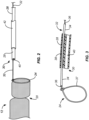
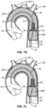
- an embolic protection device 10 comprises a filter body 12 having an open upstream end 16 and an open downstream end 18.
- the filter body 12 is typically formed from a porous mesh material, more typically a tubular porous mesh material which is preformed to have a self-sealing port 20 with an expandable opening 22 located between the open upstream end 16 and the open downstream end 18, typically closer to the open downstream end as illustrated.
- Specific folding patterns for the filter body 12 are described below with reference to Figs. 8A-8E , and several exemplary alternative folding patterns are described below in connection with Figs. 15A-15C .
- a radially expandable/collapsible support 24 is secured at the open downstream end 18 of the filter body 12, as best seen in Fig. 2 .
- the radially collapsible support 24 may comprise a tube 34 ( Fig. 3 ) having a pull wire 36 with a loop 37 formed at its distal end.
- the loop 37 is secured about the periphery of the open downstream end 18 of the filter body 12 so that it may act as a "lasso" or a "purse-string” component for opening and closing the open downstream end 18.
- the loop 37 may be closed.
- the loop 37 may be open.
- the filter body 12 may be positioned relative to a deployment catheter body 28.
- the self-sealing port 20 of the filter body 12 divides the filter body into an upstream cylindrical chamber 26A and a downstream cylindrical chamber 26B.
- Each of the chambers 26A and 26B will be generally free from internal structure, and the self-sealing port 20 will act to divide the two chambers and, in particular, to prevent passage of emboli which may enter the upstream chamber 26A into or beyond the downstream chamber 26B.
- the downstream cylindrical chamber 26B acts to receive and facilitate introduction of working catheters into and through the self-sealing port 20 in order to perform interventional procedures upstream of the filter body 12 when the filter body is deployed in the aorta or other blood vessels.
- the deployment catheter body 28 has a distal end 30 and at least a first lumen 38 for carrying the tether structure 32 and a second lumen 40 which serves as a working lumen for introducing interventional or working catheters therethrough, such as TAVR catheters for deploying prosthetic aortic valves as will be described in detail below.
- a proximal or control hub 29 is coupled to a proximal end 31 of the deployment catheter body 28.
- a proximal end 33 of the tether structure 32 extends from the control hub 29 and allows a user to manipulate the tether structure, and including both axial retraction and advancement of the tether structure as well as opening and closing of the loop 37.
- the control hub 29 also has a port 35 which opens to the second lumen 40 in the catheter body 28 for allowing passage of guide wires, working catheters, and the like.
- the filter body 12 will typically be self-expanding.
- self-expanding it is meant that the filter body will be resilient and have a normally open or expanded configuration when free from radial and/or axial constraint.
- the diameter or profile of the filter body will be reduced so that it can be intravascularly introduced to a working site in the patient's vasculature, typically over the aortic arch but optionally in other locations as well.
- the self-sealing port within the filter body will be unfolded and axially extended.
- the self-sealing port 20 will be self-forming, typically having a conical base 56 and an extending sleeve 58, as shown in Fig. 1 .
- the self-sealing port 20 will have at structure which is formed by folding and inverting the generally tubular structure of the filter body as the radius of the filter body increases and the length of the filter body axially shortens.
- the necessary fold lines will be pre-formed into the filter body, typically by heat treatment.
- the filter body will be formed as a Nitinol ® (nickel-titanium alloy) thin wire mesh which will be formed to have the fold lines described in more detail with reference to Figs. 8A-8E below.
- the filter body will be axially elongated and radially collapsed to have a low profile during delivery, typically having a delivery diameter below 12 Fr (French), often below 10 Fr.
- the filter body will typically open to an unconstrained width or diameter above 5 mm, often above 15mm more often above 25mm, and typically in the range from 25mm to 40mm.
- the filter body 12 will be introduced in its low profile configuration through a delivery sheath 42 which has been pre-placed in the patient's artery, typically through the femoral artery over the aortic arch. In order to advance the filter body into the delivery sheath 42, however, it is necessary to temporarily constrain the self-expanding filter body 12.
- a peel-away sheath 48 This may be achieved using a peel-away sheath 48, as shown in Figs. 4 and 5 .
- the filter body 12 is axially elongated and radially collapsed and drawn into the lumen of the peel-away sheath 48, as shown in Fig. 4 .
- the peel-away sheath covers the filter body 12 with the catheter body 28 extending from a proximal end of the peel-away sheath 48.
- the temporary assembly of the peel-away sheath and the catheter body 28 can be introduced over a guidewire structure 46 which has been pre-placed through a distal port 44 of the delivery sheath 42, as shown in Fig. 4 , with the sheath then being advanced through the distal port 44, as shown in Fig. 5 .
- each of the delivery sheath 42 and the peel-away sheath 48 may have ports to allow the introduction of fluids into their lumens.
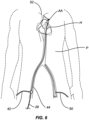
- the delivery sheath 42 will be introduced through the patient's groin into a femoral artery and up and over the aortic arch in a conventional manner.
- a second sheath 50 typically for introducing a TAVR or other interventional or working catheter, will be positioned in the contralateral femoral artery for introducing the working catheter up the aorta and over the aortic arch AA in parallel to the delivery sheath 42.
- Such positioning will be intended for prosthetic valve placement or other interventional procedures on the patient's P heart H.
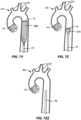
- Figs. 7A-7ZZ a particular protocol for introducing a prosthetic valve PV into the patient's native aortic valve AV will be described.
- the delivery sheath 42 is initially placed over the guidewire structure 46 as just described with reference to Fig. 6 .
- the catheter body 28 is then advanced through the inner lumen of the delivery sheath 42 such that the radially constrained filter body 12 approaches the open distal end 52 of the delivery sheath.
- the distal end of the filter body 12 will be released from constraint so that the tubular porous mesh 14 will begin to radially expand, as shown in Fig. 7B .
- the delivery sheath 42 continues to be proximally retracted, as shown Fig. 7C , so that the tubular porous mesh 14 expands and engages the inner wall of the ascending aorta immediately above the aortic valve AV.
- Fig. 7C As shown in Fig.
- the delivery sheath 42 continues to be proximally withdrawn, allowing the tubular porous mesh 14 to continue to expand and to begin covering the branch vessels BV, with relative full deployment of the upstream cylindrical chamber 26A of the filter body 12 shown in Fig. 7E .
- the self-sealing port structure 20 is at its very initial stages of being formed, with further formation being shown in Fig. 7F .
- the conical base 56 of what will become the self-sealing port 20 is largely formed, and the downstream cylindrical chamber 26B begins to form as shown in Fig. 7H .
- the downstream cylindrical chamber 26B is largely formed as shown in Fig. 7I while the self-sealing port 20 is just beginning to form.
- a narrowed segment of the tubular porous mesh 14 will begin to invert to form the sleeve structure 58 of the port 20.
- Fig. 7G the conical base 56 of what will become the self-sealing port 20 is largely formed, and the downstream cylindrical chamber 26B begins to form as shown in Fig. 7H .
- the downstream cylindrical chamber 26B is largely formed as shown in Fig. 7I while the self-sealing port 20 is just beginning to form.
- the radially collapsible support 24 in the form of the loop 37, opens to open and support the open distal end of the downstream cylindrical chamber 26. It is this support structure 24 which allows the catheter body 28 to manipulate the downstream portion of the filter body 12 so that the downstream cylindrical chamber 26B can be advanced distally or toward the aortic valve AV relative to the upstream cylindrical chamber 26A.
- the radially expandable/collapsible support 24A will also be useful when retracting the filter body 12 at the end of the procedure, as will be described in more detail below.
- the fully deployed self-sealing port 20 is shown in Fig. 7K with the sleeve 58 defining the expandable opening 22 and the conical base 58 facilitating introduction of catheters from the downstream end, as shown in more detail below.
- the guidewire structure 46 may include an external support tube which may be retracted and withdrawn to leave the guidewire in place, as shown in Fig. 7L .
- a diagnostic catheter 60 may then be advanced over the guidewire 46, as shown in Fig. 7M typically being used for angiography. This port 20 will expand to accommodate the diameter of the diagnostic catheter 60 while sealing around the catheter to prevent any emboli from passing through the port.
- another guidewire 62 may be introduced for advancing a TAVR delivery catheter 64, as shown in Fig. 7N .
- the first catheter structure 46 will typically be left in place although it is not visible in Fig. 7N .
- the TAVR delivery catheter 64 is then advanced over the patient's aortic arch AA, as shown in Fig. 7O , until it passes through the native aortic valve AV, as shown in Fig. 7P .
- a prosthetic valve PV will then be released from the TAVR catheter 64, as shown in Fig. 7Q .
- the TAVR delivery catheter 64 will be proximally retracted over the guidewire 62, as shown in Fig. 7R .
- the first guidewire 46 is also shown in Fig. 7R .
- the TAVR delivery catheter 64 continues to be withdrawn and exits through the self-sealing port 20 which then closes over the guidewire 46, as shown in Fig. 7S and 7T .
- the TAVR guidewire 62 is then pulled back through the aorta, as shown in Fig. 7T .
- the prosthetic valve PV is in place and it is necessary to withdraw the filter body 12 from the aortic arch AA.
- the tether structure 32 is manipulated to close the loop 37 of the radially collapsible support 24.
- the proximal end of the filter structure 12 is drawn to the distal end of the catheter body 28, and the catheter body 28 retracted to draw the filter body into the delivery sheath 42, as shown in Fig. 7W .
- the catheter body 28 continues to be proximally withdrawn so that it pulls the downstream cylindrical chamber 26 into the delivery sheath 42, as shown in Fig. 7X , and continues to be proximally withdrawn until the entire filter body 12 is drawn into the delivery sheath 42, as shown in Figs. 7Y, 7Z, and 7ZZ .
- the filter body and all emboli contained therein are then safely captured within the delivery sheath 42, and the delivery sheath 42 may be withdrawn from the patient and the procedure may be completed in a conventional manner.
- the porous filter mesh material may comprise a variety of knitted, woven or nonwoven fibers, filaments or wires, and will have a pore size chosen to allow blood to pass through but prevent emboli above a certain size from passing through.
- Suitable materials include resilient metals, such as shape and heat memory alloys, polymers, and combinations thereof, and the materials may optionally have an anti-thrombogenic coating (such as heparin) on their surfaces.
- the filter meshes may further incorporate materials and structures to enhance the radiopacity of the filter body. Exemplary materials include gold, platinum, palladium, or tantalum, and other metals having a greater radiopacity than the resilient metals, as well as radiopaque coatings or fillings. In other cases, the resilient metal filaments or wires may be served with thinner, more radiopaque wires or filaments.
- the filter body maybe constructed in discrete sections that are attached together, but will more typically be formed from a continuous cylindrical mesh structure that is narrowed or folded in sections to form the specific design features, typically consisting of a single such folded tubular mesh structure. Forming the device from one continuous cylindrical mesh allows the filter body to be axially stretched for deployment and/or retrieval, thereby reducing the profile of the filter.
- Another advantage of a filter formed from a single, continuous tabulate mesh material is that it will contain only smooth, rounded edges. Such edges minimize friction and snagging with catheters and the procedural tools being introduced through the filters.
- the self-sealing port may be configured as a conical structure with the access port at its narrow end, typically formed by a sleeve as described previously.
- the self-sealing port may be a simple narrowing of the cylindrical structure, e.g. a self-closing neck region which seal around catheters and other tools introduced therethrough.
- the self-sealing port can be formed by shape-setting a larger, tubular or cylindrical mesh in a reduced diameter via heat treatment or cold forming.
- the filter body may contain two or more such self-expanding port structures.
- the port 20 may accommodate a single device (such as a guidewire, catheter, valve delivery system, pacing lead, etc.), two devices or more than two devices simultaneously and can expand and contract to maintain a sufficient seal around multiple devices as needed. Further, such devices can be introduced through the downstream cylindrical chamber 26B and into the port 20 by way of the working lumen 40 of the catheter body 28 or directly by way of a second sheath 50 in an alternative access site, or in some combination thereof.
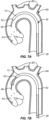
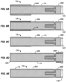
- FIGs 8A-8E a number of different patterns for forming the tubular porous mesh material 14 into a filter body 12 having the self-sealing port 20 between the upstream cylindrical chamber 26A and the downstream cylindrical chamber 26B are illustrated.
- each of the structures in Figs. 8A-8B begins with a single layer tube of a mesh material as just described.
- the tubular structure is first folded into a bi-layer structure having a fold 14A in its middle.
- the bi-layer structure is then folded back upon itself and inverted in order to form the illustrated filter body 12a having a structure which is then heat set in the fully radially expanded configuration.
- the filter body 12b of Fig. 8B similarly begins as a bi-layer tubular mesh with a single fold 14B at one end.
- the bi-layer structure is then folded similarly to the pattern of Fig. 8B , except that the open end of cylindrical chamber 26A is folded in an inwardly inverted pattern rather than in a simple fold-back pattern as shown in Fig. 8A .
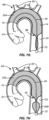
- the filter body 12c illustrated in Fig. 8C is again similar in most respects to the fold pattern of filter 12a of Fig. 8A , except that the open end of the upstream cylindrical chamber 26A has an inner layer folded over an outer layer to form a distal cuff, where the inner layer terminates within the folded-back outer layer.
- the filter body 12d illustrated in Fig. 8D is in many ways the inverse of that filter body 12a of Fig. 8A .
- a single fold 14D in the original single-layer tubular cylinder is located at the open end of the upstream cylindrical chamber 26A.
- the open downstream end of downstream chamber 26B is folded back on itself to form a cuff structure.
- Filter body 12e as illustrated in Fig. 8E is the simplest structure of all where folding of the downstream cylindrical chamber 26B is similar to that in Figs. 8A-8C , but the open end of the upstream cylindrical chamber 26A terminates with the inner and outer layers open and not folded back at all.
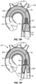
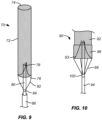
- FIG. 9 illustrates a first alternative embodiment of an embolic protection device 70.
- a filter body 72 has an open upstream end 74 and a closed downstream end 76.
- a self-sealing port 78 is formed in the closed downstream end 76, and a support structure 82 is attached at a downstream end of the filter body.
- the support structure 82 comprises a pair of struts and can be made of a material (such as a shape memory alloy) that can be compressed for delivery and expanded in situ by the release of a constraining sheath 86.
- the support is fixedly or movably attached to a deployment catheter body 80 via a collar 84.
- a distal or upstream end of the catheter body 80 passes through the closed end 76 of the filter body 72 adjacent to the self-sealing port 78.
- Fig. 10 illustrates a second alternative embodiment of an embolic protection device 90.
- a filter body 92 with a closed downstream end 93 is attached to a deployment catheter body by fully circumferential support structure 96.
- the support structure 96 comprises "stent-like" diamond elements over the region where the support structured overlaps and is attached to the mesh material of the filter 92.
- the support structure 96 is fixedly or movably attached to a deployment catheter body 94 via a collar 100 and a plurality of struts 98.
- a distal or upstream end of the catheter body 94 passes through the closed end 93 of the filter body 92 adjacent to a self-sealing port 99.
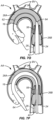
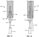
- Figs. 11 and 12 illustrate a third alternate embodiment of an embolic protection device 102 having a conical mesh self-sealing port 108 in a closed end 106 of a filter body 104.
- a deployment catheter body 114 is attached by a collar 116.
- a delivery sheath 118 is provided for delivery and traction of the filter body 104.
- a distal or upstream end of the catheter body 114 is disposed through the self-sealing port 108 and provides an introductory lumen or other path through the port adjacent to the self-sealing port 108.
- a TAVR delivery or other working catheter is introduced through the self-sealing port in parallel to the catheter body 114.
- the periphery of the self-sealing port 108 will be sufficiently compliant (elastic) to conform to and seal against both catheters simultaneously.
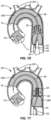
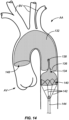
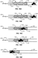
- FIGs. 13A-13C illustrate a fourth alternative embodiment of an embolic protection device 130.
- a filter body 132 comprises a double layer of mesh throughout most of the filter, with an additional layer or cuff 150 (for a total of three layers) at a downstream end to increase the anchoring strength of the filter in this portion of the device.
- Fig. 13A shows the embolic protection device 130 in its relaxed configuration
- Figs. 13B and 13C show the embolic protection device 130 as it is axially stretched in the direction of arrows 146 into a delivery or retrieval configuration.
- a self-sealing port 134 and other device features are integrally or monolithically formed within a continuous cylindrical mesh structure, these features effectively disappear when the filter body 132 is fully stretched out in the axial direction. This ability to stretch out and eliminate internal structure minimizes the device profile.
- the construction of the filter from one continuous cylindrical surface also avoids manufacturing complexity and maintains a smooth contact surface throughout the device to reduce the friction of procedural tools passing through the filter.
- the filter body is attached to a deployment catheter body 144 by a stent-like peripheral support structure 140 which overlaps or overlies a downstream cylindrical chamber 139 of the filter body 132.
- the self-sealing port 134 may comprise a conical base 136 and a sleeve 138 generally as described previously.
- Fig. 14 illustrates the embolic protection device 130 deployed over a patient's aortic arch to protect the branch vessels as an interventional catheter is delivered in an upstream direction through the self-sealing port 134 to perform a procedure, such as valvuloplasty or TAVR, at the aortic valve AV.
- a procedure such as valvuloplasty or TAVR
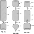
- Figs. 15A-15C shows alternative configurations of the filter body.
- Fig. 15A shows a filter body 160 comprising an upstream cylindrical chamber 162 and a downstream cylindrical chamber 164 separated by a simple narrowing or neck 166 formed in the cylindrical mesh material.
- the cylindrical mesh material may be single-walled, double-walled, have more than two layers over some or all of the wall area, or combinations thereof, and this filter body configuration can be combined in most or all of the embodiments of the embolic protection devices described previously.
- Fig. 15B shows a filter body 170 comprising an upstream cylindrical chamber 172, a central cylindrical chamber 174, and a downstream cylindrical chamber 178 separated by a necks 180 and 182, respectively. It will be appreciated that such multiple cylindrical chambers could be separated by any of the self-closing port structures described previously.
- the downstream end of the downstream cylindrical chamber 178 may be gathered or closed, as illustrated, and the filter body 170 with a closed downstream end may find particular use in the clot capture configurations described in Figs. 16A-16E below.
- the cylindrical mesh material of filter body 170 may be single-walled, double-walled, have more than two layers, or be combinations thereof, and multi-chamber filter body configurations can be combined in most or all of the embodiments of the embolic protection devices described previously, although the downstream end of the downstream chamber will have to be opened.
- Fig. 15C shows a filter body 200 comprising an upstream cylindrical chamber 202, a central cylindrical chamber 204, and a downstream cylindrical chamber 206 separated by a neck 208 and a self-sealing port 210, respectively.
- the downstream end of the downstream cylindrical chamber 206 is open, and the multi-chamber filter body 200 can be combined in most or all of the embodiments of the embolic protection devices described previously.
- the cylindrical mesh material of filter body 200 may be single-walled, double-walled, have more than two layers, or be combinations thereof.
- Figs. 16A-16E show a specific procedural using the filter body 170 of Fig. 15B for capturing clot and/or thrombus in a cardiac, peripheral, or cerebral blood vessel BV. Such devices and protocols will be particularly useful for clot/thrombus retrieval in a cranial vessel to treat acute ischemic stroke.
- the gathered end 179 of the filter body 170 is attached to a distal end of a deployment catheter 210, and the catheter 210 is advanced through a microcatheter 230 ( Fig. 16E ).
- a clot capture catheter 220 such as a Merci ® retriever catheter, having a clot capture element 222, such as a helical tip at its distal end is advanced through the catheter 220, the filter body 170, and into the clot/thrombus THR, as shown in Fig. 16B .
- the clot capture catheter 220 is then pulled proximally to draw the clot/thrombus THR through neck 180 into the central chamber 174, as shown in Figs.16B-16D .
- the upstream neck 180 will be configured to stretch open to allow the clot retrieval device and the ensnared thrombus and clot to pass through, and to close after the clot and/or thrombus are fully enclosed within the central cylindrical chamber 174. Any debris that may come loose from the clot and thrombus is contained by the fully-closed necks 180 and 182 ( Fig. 16D ), the assembly of the clot retriever 220, the filter body 170, and catheter body 220 may be safely withdrawn through the microcatheter 230.
Landscapes
- Health & Medical Sciences (AREA)
- Life Sciences & Earth Sciences (AREA)
- General Health & Medical Sciences (AREA)
- Animal Behavior & Ethology (AREA)
- Engineering & Computer Science (AREA)
- Biomedical Technology (AREA)
- Heart & Thoracic Surgery (AREA)
- Veterinary Medicine (AREA)
- Public Health (AREA)
- Vascular Medicine (AREA)
- Cardiology (AREA)
- Oral & Maxillofacial Surgery (AREA)
- Transplantation (AREA)
- Surgery (AREA)
- Nuclear Medicine, Radiotherapy & Molecular Imaging (AREA)
- Medical Informatics (AREA)
- Molecular Biology (AREA)
- Orthopedic Medicine & Surgery (AREA)
- Pathology (AREA)
- Surgical Instruments (AREA)
- Prostheses (AREA)
Claims (13)
- Einen Filterkörper (12), der aus einem röhrenförmigen porösen Maschenmaterial besteht, mit einem offenen stromaufwärtigen Ende (16) und einem offenen stromabwärtigen Ende (18), wobei das röhrenförmige poröse Maschenmaterial vorgeformt ist, sodass es sich beim Expandieren in ein erstes, selbstabdichtendes Tor (20) verwandelt, das von jedem der genannten Enden nach innen versetzt ist, eine stromabwärts offene zylindrische Kammer (26B) und eine stromaufwärts offene zylindrische Kammer (26A) bildet, wobei das selbstabdichtende Tor (20) einen Wandabschnitt des röhrenförmigen porösen Maschenmaterials umfasst, wobei das selbstabdichtende Tor eine dehnbare Öffnung umfasst, die dazu konfiguriert ist, sich an mindestens einen Arbeitskatheter anzupassen, der hindurchgeführt wird, wobei die stromabwärts offene zylindrische Kammer (26B) sich zwischen einem stromabwärtigen Ende des selbstabdichtenden Tors (20) und dem stromabwärtigen Ende des Filterkörpers (12) befindet, und wobei die stromaufwärts offene zylindrische Kammer (26A) sich zwischen einem stromaufwärtigen Ende des selbstabdichtenden Tors (20) und dem stromaufwärtigen Ende des Filterkörpers (12) befindet;
und
einen Katheterkörper mit einem distalen Ende, das mit dem stromabwärtigen Ende des Filterkörpers verbunden ist. - Ein luminales Embolieauffanggerät gemäß Anspruch 1, wobei das poröse Maschenmaterial ein Gewebe aus gestrickten, gewebten oder nicht gewebten Fasern, Filamenten oder Drähten umfasst, mit einer Porengröße, die so gewählt ist, dass Embolien über einer vorgegebenen Größe nicht hindurchtreten können.
- Ein luminales Embolieauffanggerät gemäß Anspruch 2, wobei das Gewebe über mindestens einen Abschnitt des röhrenförmigen porösen Maschenmaterials doppelwandig ist.
- Ein Embolieschutzgerät gemäß Anspruch 2, wobei das poröse Maschenmaterial aus einem elastischen Metall, Polymermaterial, verformbaren Material, plastisch verformbaren Material, einem Formgedächtnismaterial oder Kombinationen davon besteht.
- Ein Embolieschutzgerät gemäß Anspruch 2, wobei das poröse Maschenmaterial eine antithrombogene Beschichtung auf seiner Oberfläche aufweist.
- Ein Embolieschutzgerät gemäß Anspruch 2, wobei das poröse Maschenmaterial eine Porengröße im Bereich von etwa 1 mm bis etwa 0,1 mm aufweist.
- Ein luminales Embolieauffanggerät gemäß Anspruch 1, wobei das erste Tor (20) einen Wandabschnitt des röhrenförmigen porösen Maschenmaterials umfasst, der so vorgeformt ist, dass er sich radial nach innen faltet oder schließt, wenn andere Wandabschnitte beim Lösen von radialem Zwang expandieren.
- Ein Embolieschutzgerät gemäß Anspruch 7, wobei der Wandabschnitt invertiert wird, um das Tor (20) mit einer kegelförmigen Öffnung auf der stromabwärtigen Seite zu bilden.
- Ein Embolieschutzgerät gemäß Anspruch 8, wobei der invertierte Wandabschnitt des röhrenförmigen porösen Maschenmaterials einen elastisch geschlossenen Hülsenabschnitt (58) aufweist, der sich in stromaufwärtiger Richtung von einer Spitze der kegelförmigen Öffnung erstreckt und die erweiterbare Öffnung des Tors (20) definiert.
- Ein Embolieschutzgerät gemäß Anspruch 7, wobei der Wandabschnitt des röhrenförmigen porösen Maschenmaterials radial nach innen verengt ist, um die erweiterbare Öffnung des Tors (20) zu definieren.
- Ein Embolieschutzgerät gemäß Anspruch 7, wobei das röhrenförmige poröse Maschenmaterial mindestens ein zweites Tor umfasst, das in Längsrichtung vom ersten Tor (20) angeordent ist, wobei das zweite Tor einen Wandabschnitt des röhrenförmigen porösen Maschenmaterials umfasst, der sich radial nach innen faltet oder schließt, wenn andere Wandabschnitte beim Lösen von radialem Zwang expandieren.
- Ein Embolieschutzgerät gemäß Anspruch 11, wobei der Filterkörper eine zentrale offene zylindrische Kammer zwischen einem stromabwärtigen Ende des ersten Tors (20) und einem stromaufwärtigen Ende des zweiten Tors aufweist.
- Ein Blutgerinnsel-Rückholsystem, das folgendes umfasst: ein Embolieschutzgerät (10) gemäß Anspruch 12; und einen Arbeitskatheter zur Blutgerinnselentfernung mit einem Blutgerinnselaufnahme-Ende, wobei der Katheter so konfiguriert ist, dass er das zurückgeholte Blutgerinnsel in stromabwärtiger Richtung durch das offene stromaufwärtige Ende des Filterkörpers in die zentrale Kammer zieht.
Priority Applications (2)
| Application Number | Priority Date | Filing Date | Title |
|---|---|---|---|
| EP25157249.1A EP4566573A3 (de) | 2015-12-29 | 2016-12-20 | Intraprozedurale embolieschutzvorrichtung mit mehrfachzugang |
| EP24209719.4A EP4491157A3 (de) | 2015-12-29 | 2016-12-20 | Intraprozedurale embolieschutzvorrichtung mit mehrfachzugang |
Applications Claiming Priority (5)
| Application Number | Priority Date | Filing Date | Title |
|---|---|---|---|
| US201562272643P | 2015-12-29 | 2015-12-29 | |
| US201662294018P | 2016-02-11 | 2016-02-11 | |
| US201662297053P | 2016-02-18 | 2016-02-18 | |
| US15/137,924 US10617509B2 (en) | 2015-12-29 | 2016-04-25 | Multi-access intraprocedural embolic protection device |
| PCT/US2016/067686 WO2017116828A1 (en) | 2015-12-29 | 2016-12-20 | Multi-access intraprocedural embolic protection device |
Related Child Applications (4)
| Application Number | Title | Priority Date | Filing Date |
|---|---|---|---|
| EP24209719.4A Division-Into EP4491157A3 (de) | 2015-12-29 | 2016-12-20 | Intraprozedurale embolieschutzvorrichtung mit mehrfachzugang |
| EP24209719.4A Division EP4491157A3 (de) | 2015-12-29 | 2016-12-20 | Intraprozedurale embolieschutzvorrichtung mit mehrfachzugang |
| EP25157249.1A Division-Into EP4566573A3 (de) | 2015-12-29 | 2016-12-20 | Intraprozedurale embolieschutzvorrichtung mit mehrfachzugang |
| EP25157249.1A Division EP4566573A3 (de) | 2015-12-29 | 2016-12-20 | Intraprozedurale embolieschutzvorrichtung mit mehrfachzugang |
Publications (5)
| Publication Number | Publication Date |
|---|---|
| EP3397178A1 EP3397178A1 (de) | 2018-11-07 |
| EP3397178A4 EP3397178A4 (de) | 2019-09-04 |
| EP3397178C0 EP3397178C0 (de) | 2025-02-12 |
| EP3397178B1 true EP3397178B1 (de) | 2025-02-12 |
| EP3397178B8 EP3397178B8 (de) | 2025-03-26 |
Family
ID=59087545
Family Applications (3)
| Application Number | Title | Priority Date | Filing Date |
|---|---|---|---|
| EP16882367.2A Active EP3397178B8 (de) | 2015-12-29 | 2016-12-20 | Intraprozedurale embolieschutzvorrichtung mit mehrfachzugang |
| EP24209719.4A Pending EP4491157A3 (de) | 2015-12-29 | 2016-12-20 | Intraprozedurale embolieschutzvorrichtung mit mehrfachzugang |
| EP25157249.1A Pending EP4566573A3 (de) | 2015-12-29 | 2016-12-20 | Intraprozedurale embolieschutzvorrichtung mit mehrfachzugang |
Family Applications After (2)
| Application Number | Title | Priority Date | Filing Date |
|---|---|---|---|
| EP24209719.4A Pending EP4491157A3 (de) | 2015-12-29 | 2016-12-20 | Intraprozedurale embolieschutzvorrichtung mit mehrfachzugang |
| EP25157249.1A Pending EP4566573A3 (de) | 2015-12-29 | 2016-12-20 | Intraprozedurale embolieschutzvorrichtung mit mehrfachzugang |
Country Status (7)
| Country | Link |
|---|---|
| US (5) | US10617509B2 (de) |
| EP (3) | EP3397178B8 (de) |
| JP (1) | JP6854821B2 (de) |
| KR (1) | KR102732643B1 (de) |
| CN (2) | CN108738303B (de) |
| DE (1) | DE202016009224U1 (de) |
| WO (1) | WO2017116828A1 (de) |
Families Citing this family (65)
| Publication number | Priority date | Publication date | Assignee | Title |
|---|---|---|---|---|
| EP2800602B1 (de) | 2012-01-06 | 2017-08-02 | Emboline, Inc. | Integrierte embolieschutzvorrichtungen |
| KR102663563B1 (ko) | 2015-11-09 | 2024-05-03 | 레디액션 엘티디. | 방사선 차폐 장치 및 그 적용 |
| US10500046B2 (en) * | 2015-12-14 | 2019-12-10 | Medtronic, Inc. | Delivery system having retractable wires as a coupling mechanism and a deployment mechanism for a self-expanding prosthesis |
| US10617509B2 (en) | 2015-12-29 | 2020-04-14 | Emboline, Inc. | Multi-access intraprocedural embolic protection device |
| CN113350657A (zh) | 2016-02-24 | 2021-09-07 | 禾木(中国)生物工程有限公司 | 柔性增强的神经血管导管 |
| WO2018013515A1 (en) * | 2016-07-12 | 2018-01-18 | Tendyne Holdings, Inc. | Apparatus and methods for trans-septal retrieval of prosthetic heart valves |
| WO2018129194A1 (en) | 2017-01-06 | 2018-07-12 | Incept, Llc | Thromboresistant coatings for aneurysm treatment devices |
| WO2019089821A1 (en) * | 2017-10-31 | 2019-05-09 | Miami Medtech Llc | Embolic protection devices and methods of embolic protection |
| DE102018105671A1 (de) * | 2018-03-12 | 2019-09-12 | Phenox Gmbh | Thrombektomievorrichtung |
| ES2952935T3 (es) * | 2018-03-27 | 2023-11-07 | Maduro Discovery Llc | Dispositivo accesorio para proporcionar neuroprotección durante procedimientos de intervención |
| WO2019195860A2 (en) | 2018-04-04 | 2019-10-10 | Vdyne, Llc | Devices and methods for anchoring transcatheter heart valve |
| US11395665B2 (en) | 2018-05-01 | 2022-07-26 | Incept, Llc | Devices and methods for removing obstructive material, from an intravascular site |
| JP2021522885A (ja) | 2018-05-01 | 2021-09-02 | インセプト・リミテッド・ライアビリティ・カンパニーIncept,Llc | 血管内部位から閉塞性物質を除去する装置および方法 |
| CN112584799A (zh) * | 2018-06-29 | 2021-03-30 | 阿万泰血管公司 | 用于移植物和部署装置的系统和方法 |
| WO2020010310A1 (en) | 2018-07-06 | 2020-01-09 | Imperative Care, Inc. | Sealed neurovascular extendable catheter |
| US11471582B2 (en) | 2018-07-06 | 2022-10-18 | Incept, Llc | Vacuum transfer tool for extendable catheter |
| US11278437B2 (en) | 2018-12-08 | 2022-03-22 | Vdyne, Inc. | Compression capable annular frames for side delivery of transcatheter heart valve replacement |
| US10595994B1 (en) | 2018-09-20 | 2020-03-24 | Vdyne, Llc | Side-delivered transcatheter heart valve replacement |
| US10321995B1 (en) | 2018-09-20 | 2019-06-18 | Vdyne, Llc | Orthogonally delivered transcatheter heart valve replacement |
| US12186187B2 (en) | 2018-09-20 | 2025-01-07 | Vdyne, Inc. | Transcatheter deliverable prosthetic heart valves and methods of delivery |
| US11071627B2 (en) | 2018-10-18 | 2021-07-27 | Vdyne, Inc. | Orthogonally delivered transcatheter heart valve frame for valve in valve prosthesis |
| US11344413B2 (en) | 2018-09-20 | 2022-05-31 | Vdyne, Inc. | Transcatheter deliverable prosthetic heart valves and methods of delivery |
| US11109969B2 (en) | 2018-10-22 | 2021-09-07 | Vdyne, Inc. | Guidewire delivery of transcatheter heart valve |
| US20220000601A1 (en) * | 2018-11-15 | 2022-01-06 | Baleen Medical Llc | Methods, systems, and devices for embolic protection |
| US11253359B2 (en) | 2018-12-20 | 2022-02-22 | Vdyne, Inc. | Proximal tab for side-delivered transcatheter heart valves and methods of delivery |
| JP7548588B2 (ja) | 2019-01-02 | 2024-09-10 | ラディアクション リミテッド | 放射線保護装置およびそのための材料 |
| JP7498970B2 (ja) | 2019-01-02 | 2024-06-13 | ラディアクション リミテッド | 患者頭部保護デバイス |
| WO2020146842A1 (en) | 2019-01-10 | 2020-07-16 | Vdyne, Llc | Anchor hook for side-delivery transcatheter heart valve prosthesis |
| US11185409B2 (en) | 2019-01-26 | 2021-11-30 | Vdyne, Inc. | Collapsible inner flow control component for side-delivered transcatheter heart valve prosthesis |
| US11273032B2 (en) | 2019-01-26 | 2022-03-15 | Vdyne, Inc. | Collapsible inner flow control component for side-deliverable transcatheter heart valve prosthesis |
| EP4541316A3 (de) | 2019-02-13 | 2025-07-09 | Emboline, Inc. | Katheter mit integrierter embolieschutzvorrichtung |
| CA3132162A1 (en) | 2019-03-05 | 2020-09-10 | Vdyne, Inc. | Tricuspid regurgitation control devices for orthogonal transcatheter heart valve prosthesis |
| US11076956B2 (en) | 2019-03-14 | 2021-08-03 | Vdyne, Inc. | Proximal, distal, and anterior anchoring tabs for side-delivered transcatheter mitral valve prosthesis |
| US11173027B2 (en) | 2019-03-14 | 2021-11-16 | Vdyne, Inc. | Side-deliverable transcatheter prosthetic valves and methods for delivering and anchoring the same |
| US11766539B2 (en) | 2019-03-29 | 2023-09-26 | Incept, Llc | Enhanced flexibility neurovascular catheter |
| EP3718505A1 (de) * | 2019-04-05 | 2020-10-07 | Aorticlab Sarl | Transkatheter-anti-embolie-filter für arterielle und venöse gefässe |
| CN109998749B (zh) * | 2019-04-12 | 2021-07-30 | 武汉唯柯医疗科技有限公司 | 带远端保护的颅内血管支架 |
| CA3138875A1 (en) | 2019-05-04 | 2020-11-12 | Vdyne, Inc. | Cinch device and method for deployment of a side-delivered prosthetic heart valve in a native annulus |
| IL312949A (en) | 2019-06-15 | 2024-07-01 | Maduro Discovery Llc | Catheter construction |
| CN114340504B (zh) | 2019-07-02 | 2025-09-02 | 瑞迪艾森有限公司 | 可展开辐射防护屏罩 |
| US11707351B2 (en) | 2019-08-19 | 2023-07-25 | Encompass Technologies, Inc. | Embolic protection and access system |
| CA3152042A1 (en) | 2019-08-20 | 2021-02-25 | Vdyne, Inc. | Delivery and retrieval devices and methods for side-deliverable transcatheter prosthetic valves |
| CN114630665B (zh) | 2019-08-26 | 2025-06-17 | 维迪内股份有限公司 | 可侧面输送的经导管假体瓣膜及其输送和锚定方法 |
| EP4044906B1 (de) | 2019-10-15 | 2025-03-12 | Kandu Health, Inc. | Systeme und verfahren zur mehrgrössenhubdetektion |
| WO2021127004A1 (en) * | 2019-12-18 | 2021-06-24 | Imperative Care, Inc. | Methods and systems for treating venous thromboembolic disease |
| US20210315598A1 (en) | 2019-12-18 | 2021-10-14 | Imperative Care, Inc. | Methods of placing large bore aspiration catheters |
| US20230248500A1 (en) | 2019-12-18 | 2023-08-10 | Imperative Care, Inc. | Sterile field clot capture module for use in thrombectomy system |
| US11633272B2 (en) | 2019-12-18 | 2023-04-25 | Imperative Care, Inc. | Manually rotatable thrombus engagement tool |
| US11234813B2 (en) | 2020-01-17 | 2022-02-01 | Vdyne, Inc. | Ventricular stability elements for side-deliverable prosthetic heart valves and methods of delivery |
| EP4117762A4 (de) | 2020-03-10 | 2024-05-08 | Imperative Care, Inc. | Neurovaskulärer katheter mit erhöhter flexibilität |
| CN111658226B (zh) * | 2020-07-21 | 2024-08-09 | 石家庄帝中医疗器械科技有限公司 | 脑保护系统及使用方法 |
| US11207497B1 (en) | 2020-08-11 | 2021-12-28 | Imperative Care, Inc. | Catheter with enhanced tensile strength |
| CN111759531A (zh) * | 2020-08-11 | 2020-10-13 | 石家庄帝中医疗器械科技有限公司 | 脑保护装置及主动脉瓣置换手术器械 |
| CN112022425A (zh) * | 2020-09-11 | 2020-12-04 | 复旦大学附属中山医院 | 血栓过滤装置 |
| US11786354B2 (en) * | 2020-10-01 | 2023-10-17 | Gil Vardi | Embolic filter device |
| WO2022177618A1 (en) * | 2021-02-19 | 2022-08-25 | Emboline, Inc. | Methods and systems for placing embolic filters in an aortic arch |
| EP4112004A1 (de) * | 2021-07-01 | 2023-01-04 | Medtronic Inc. | Emboliefilter |
| US12376928B2 (en) | 2021-08-12 | 2025-08-05 | Imperative Care, Inc. | Catheter drive system for supra-aortic access |
| CN113729860A (zh) * | 2021-08-16 | 2021-12-03 | 万漉医疗科技(江苏)有限公司 | 血栓清除装置及方法 |
| USD1077996S1 (en) | 2021-10-18 | 2025-06-03 | Imperative Care, Inc. | Inline fluid filter |
| CN113974712B (zh) * | 2021-10-29 | 2024-07-26 | 上海御瓣医疗科技有限公司 | 一种在心血管手术中对脑血管保护的装置 |
| CN114767352A (zh) * | 2022-05-27 | 2022-07-22 | 首都医科大学附属北京安贞医院 | 一种用于心外科术中的支架放置装置 |
| CN114788746A (zh) * | 2022-05-27 | 2022-07-26 | 首都医科大学附属北京安贞医院 | 一种用于心外科术中的远端滤器脑保护装置 |
| DE112023005161T5 (de) * | 2022-12-13 | 2025-10-02 | Transaortic Medical, Inc. | Niedrigprofilige(s) embolieschutzvorrichtung und -system |
| US12171917B1 (en) | 2024-01-08 | 2024-12-24 | Imperative Care, Inc. | Devices for blood capture and reintroduction during aspiration procedure |
Citations (10)
| Publication number | Priority date | Publication date | Assignee | Title |
|---|---|---|---|---|
| WO1996001591A1 (en) | 1994-07-08 | 1996-01-25 | Microvena Corporation | Method of forming medical devices; intravascular occlusion devices |
| WO1997027808A1 (en) | 1996-02-02 | 1997-08-07 | Regents Of The University Of California | Clot capture coil |
| US6361545B1 (en) | 1997-09-26 | 2002-03-26 | Cardeon Corporation | Perfusion filter catheter |
| US20030176884A1 (en) | 2002-03-12 | 2003-09-18 | Marwane Berrada | Everted filter device |
| US20060287668A1 (en) | 2005-06-16 | 2006-12-21 | Fawzi Natalie V | Apparatus and methods for intravascular embolic protection |
| US20110213403A1 (en) | 2010-02-23 | 2011-09-01 | Maria Aboytes | Devices and methods for vascular recanalization |
| WO2012052982A1 (en) | 2010-10-22 | 2012-04-26 | Neuravi Limited | Clot engagement and removal system |
| US20130178891A1 (en) | 2012-01-06 | 2013-07-11 | Emboline, Inc. | Integrated embolic protection devices |
| US20140249568A1 (en) | 2013-03-01 | 2014-09-04 | Aga Medical Corporation | Embolic protection pass through tube |
| WO2014150288A2 (en) | 2013-03-15 | 2014-09-25 | Insera Therapeutics, Inc. | Vascular treatment devices and methods |
Family Cites Families (151)
| Publication number | Priority date | Publication date | Assignee | Title |
|---|---|---|---|---|
| US4790809A (en) | 1985-08-29 | 1988-12-13 | Medical Engineering Corporation | Ureteral stent |
| US4723549A (en) | 1986-09-18 | 1988-02-09 | Wholey Mark H | Method and apparatus for dilating blood vessels |
| US5108419A (en) | 1990-08-16 | 1992-04-28 | Evi Corporation | Endovascular filter and method for use thereof |
| US5197485A (en) | 1991-10-15 | 1993-03-30 | Pilling Co. | Method and apparatus for sampling aortic plaque |
| US6808520B1 (en) | 1991-12-13 | 2004-10-26 | Endovascular Technologies, Inc. | Dual valve, flexible expandable sheath and method |
| IT1269443B (it) | 1994-01-19 | 1997-04-01 | Stefano Nazari | Protesi vascolare per la sostituzione o il rivestimento interno di vasi sanguigni di medio e grande diametro e dispositivo per la sua applicazione senza interruzione del flusso ematico |
| US5643227A (en) | 1995-01-19 | 1997-07-01 | Stevens; Robert C. | Hemostasis cannula valve apparatus and method of using same |
| WO1996030073A1 (en) | 1995-03-30 | 1996-10-03 | Heartport, Inc. | Endovascular cardiac venting catheter and method |
| ATE290077T1 (de) | 1995-09-29 | 2005-03-15 | Univ Siena | Regulierte gene und ihre verwendungen |
| US5989281A (en) | 1995-11-07 | 1999-11-23 | Embol-X, Inc. | Cannula with associated filter and methods of use during cardiac surgery |
| US5769816A (en) | 1995-11-07 | 1998-06-23 | Embol-X, Inc. | Cannula with associated filter |
| US5807327A (en) | 1995-12-08 | 1998-09-15 | Ethicon, Inc. | Catheter assembly |
| US5662671A (en) | 1996-07-17 | 1997-09-02 | Embol-X, Inc. | Atherectomy device having trapping and excising means for removal of plaque from the aorta and other arteries |
| CA2575865C (en) * | 1996-07-17 | 2009-09-22 | C.R. Bard, Inc. | Removable embolus blood clot filter |
| US5797880A (en) | 1996-09-05 | 1998-08-25 | Becton And Dickinson And Company | Catheter and placement needle assembly with retractable needle |
| US6391044B1 (en) | 1997-02-03 | 2002-05-21 | Angioguard, Inc. | Vascular filter system |
| US6254633B1 (en) | 1997-02-12 | 2001-07-03 | Corvita Corporation | Delivery device for a medical device having a constricted region |
| US5814064A (en) | 1997-03-06 | 1998-09-29 | Scimed Life Systems, Inc. | Distal protection device |
| US5769819A (en) | 1997-04-24 | 1998-06-23 | Medtronic, Inc. | Catheter distal tip component |
| US5911734A (en) | 1997-05-08 | 1999-06-15 | Embol-X, Inc. | Percutaneous catheter and guidewire having filter and medical device deployment capabilities |
| US6258120B1 (en) | 1997-12-23 | 2001-07-10 | Embol-X, Inc. | Implantable cerebral protection device and methods of use |
| US5800525A (en) | 1997-06-04 | 1998-09-01 | Vascular Science, Inc. | Blood filter |
| US6340356B1 (en) | 1997-09-23 | 2002-01-22 | NAVIA JOSé ANTONIO | Intraluminal catheter with expandable tubular open-walled element |
| US6371935B1 (en) | 1999-01-22 | 2002-04-16 | Cardeon Corporation | Aortic catheter with flow divider and methods for preventing cerebral embolization |
| US6120534A (en) | 1997-10-29 | 2000-09-19 | Ruiz; Carlos E. | Endoluminal prosthesis having adjustable constriction |
| US6461370B1 (en) | 1998-11-03 | 2002-10-08 | C. R. Bard, Inc. | Temporary vascular filter guide wire |
| ES2336592T3 (es) * | 1997-11-07 | 2010-04-14 | Salviac Limited | Dispositivo de proteccion embolica. |
| DE69818302D1 (de) | 1997-12-15 | 2003-10-23 | Cardeon Corp | Perfusionsverbindungsvorrichtung |
| US6695864B2 (en) | 1997-12-15 | 2004-02-24 | Cardeon Corporation | Method and apparatus for cerebral embolic protection |
| US6254563B1 (en) | 1997-12-15 | 2001-07-03 | Cardeon Corporation | Perfusion shunt apparatus and method |
| IL124958A0 (en) | 1998-06-16 | 1999-01-26 | Yodfat Ofer | Implantable blood filtering device |
| US5928261A (en) | 1998-06-29 | 1999-07-27 | Ruiz; Carlos E. | Removable vascular filter, catheter system and methods of use |
| US6547760B1 (en) | 1998-08-06 | 2003-04-15 | Cardeon Corporation | Aortic catheter with porous aortic arch balloon and methods for selective aortic perfusion |
| US6013051A (en) | 1998-10-22 | 2000-01-11 | Medtronic, Inc. | Filtered access port with filter bypass for accessing body fluid samples |
| US6152144A (en) | 1998-11-06 | 2000-11-28 | Appriva Medical, Inc. | Method and device for left atrial appendage occlusion |
| US6083239A (en) | 1998-11-24 | 2000-07-04 | Embol-X, Inc. | Compliant framework and methods of use |
| US7018401B1 (en) | 1999-02-01 | 2006-03-28 | Board Of Regents, The University Of Texas System | Woven intravascular devices and methods for making the same and apparatus for delivery of the same |
| US6355051B1 (en) | 1999-03-04 | 2002-03-12 | Bioguide Consulting, Inc. | Guidewire filter device |
| IL128938A0 (en) | 1999-03-11 | 2000-02-17 | Mind Guard Ltd | Implantable stroke treating device |
| US6245012B1 (en) | 1999-03-19 | 2001-06-12 | Nmt Medical, Inc. | Free standing filter |
| US6267776B1 (en) | 1999-05-03 | 2001-07-31 | O'connell Paul T. | Vena cava filter and method for treating pulmonary embolism |
| DE10084521T1 (de) | 1999-05-07 | 2002-06-20 | Salviac Ltd | Embolieschutzgerät |
| US7229463B2 (en) | 1999-07-30 | 2007-06-12 | Angioguard, Inc. | Vascular filter system for cardiopulmonary bypass |
| WO2001015629A1 (en) | 1999-08-27 | 2001-03-08 | Microvena Corporation | Slideable vascular filter |
| GB2369575A (en) | 2000-04-20 | 2002-06-05 | Salviac Ltd | An embolic protection system |
| US6520978B1 (en) | 2000-05-15 | 2003-02-18 | Intratherapeutics, Inc. | Emboli filter |
| US6602271B2 (en) | 2000-05-24 | 2003-08-05 | Medtronic Ave, Inc. | Collapsible blood filter with optimal braid geometry |
| WO2002005888A1 (en) | 2000-06-30 | 2002-01-24 | Viacor Incorporated | Intravascular filter with debris entrapment mechanism |
| US6485501B1 (en) | 2000-08-11 | 2002-11-26 | Cordis Corporation | Vascular filter system with guidewire and capture mechanism |
| US6511496B1 (en) * | 2000-09-12 | 2003-01-28 | Advanced Cardiovascular Systems, Inc. | Embolic protection device for use in interventional procedures |
| US20040098091A1 (en) | 2000-11-17 | 2004-05-20 | Raimund Erbel | Endovascular prosthesis |
| US20020128680A1 (en) | 2001-01-25 | 2002-09-12 | Pavlovic Jennifer L. | Distal protection device with electrospun polymer fiber matrix |
| US7044958B2 (en) | 2001-04-03 | 2006-05-16 | Medtronic Vascular, Inc. | Temporary device for capturing embolic material |
| US6746469B2 (en) | 2001-04-30 | 2004-06-08 | Advanced Cardiovascular Systems, Inc. | Balloon actuated apparatus having multiple embolic filters, and method of use |
| US7201761B2 (en) | 2001-06-29 | 2007-04-10 | Medtronic, Inc. | Method and apparatus for resecting and replacing an aortic valve |
| CN100409818C (zh) * | 2001-07-06 | 2008-08-13 | 周星 | 可回收血栓临时滤器 |
| US20040138692A1 (en) | 2003-01-13 | 2004-07-15 | Scimed Life Systems, Inc. | Embolus extractor |
| EP1455684A2 (de) | 2001-11-23 | 2004-09-15 | Mindguard Ltd | Implantierbare intraluminale schutzvorrichtung und verfahren zu ihrer verwendung für die stabilisierung von atheromen |
| WO2003047648A2 (en) | 2001-12-05 | 2003-06-12 | Sagax Inc. | Endovascular device for entrapment of particulate matter and method for use |
| US20030144686A1 (en) * | 2002-01-30 | 2003-07-31 | Embol-X, Inc. | Distal filtration devices and methods of use during aortic procedures |
| AU2003209966A1 (en) | 2002-03-05 | 2003-09-16 | Salviac Limited | An embolic protection system |
| US8070769B2 (en) | 2002-05-06 | 2011-12-06 | Boston Scientific Scimed, Inc. | Inverted embolic protection filter |
| US8114114B2 (en) | 2002-08-27 | 2012-02-14 | Emboline, Inc. | Embolic protection device |
| WO2004021922A2 (en) | 2002-09-03 | 2004-03-18 | Morrill Richard J | Arterial embolic filter deployed from catheter |
| DE10258708A1 (de) | 2002-12-12 | 2004-07-08 | Simag GmbH Systeme und Instrumente für die Magnetresonanztomographie | Gefäßfilter |
| US7625389B2 (en) | 2002-12-30 | 2009-12-01 | Boston Scientific Scimed, Inc. | Embolic protection device |
| US7235060B2 (en) | 2003-03-27 | 2007-06-26 | Codman & Shurtleff, Inc. | Hydrocephalus shunt system with endoscopic placement features |
| DE602004023350D1 (de) | 2003-04-30 | 2009-11-12 | Medtronic Vascular Inc | Perkutaneingesetzte provisorische Klappe |
| US7537600B2 (en) | 2003-06-12 | 2009-05-26 | Boston Scientific Scimed, Inc. | Valved embolic protection filter |
| US20050004594A1 (en) | 2003-07-02 | 2005-01-06 | Jeffrey Nool | Devices and methods for aspirating from filters |
| US8337519B2 (en) | 2003-07-10 | 2012-12-25 | Boston Scientific Scimed, Inc. | Embolic protection filtering device |
| JP4712707B2 (ja) | 2003-09-12 | 2011-06-29 | ルビコン メディカル インコーポレイテッド | 塞栓の予防および塞栓材料の除去を行うための方法、システム、および器具。 |
| US20050060017A1 (en) | 2003-09-15 | 2005-03-17 | Fischell Robert E. | Means and method for the treatment of cerebral aneurysms |
| US7604650B2 (en) | 2003-10-06 | 2009-10-20 | 3F Therapeutics, Inc. | Method and assembly for distal embolic protection |
| US7101396B2 (en) | 2003-10-06 | 2006-09-05 | 3F Therapeutics, Inc. | Minimally invasive valve replacement system |
| US8840663B2 (en) | 2003-12-23 | 2014-09-23 | Sadra Medical, Inc. | Repositionable heart valve method |
| US7780725B2 (en) | 2004-06-16 | 2010-08-24 | Sadra Medical, Inc. | Everting heart valve |
| US20050137696A1 (en) | 2003-12-23 | 2005-06-23 | Sadra Medical | Apparatus and methods for protecting against embolization during endovascular heart valve replacement |
| US20050159773A1 (en) | 2004-01-20 | 2005-07-21 | Scimed Life Systems, Inc. | Expandable retrieval device with dilator tip |
| US7706179B2 (en) * | 2004-08-04 | 2010-04-27 | The Florida International University Board Of Trustees | Three dimensional magnetic memory and/or recording device |
| US20060100658A1 (en) | 2004-11-09 | 2006-05-11 | Hiroyuki Obana | Interventional guiding sheath system and method of use |
| US20060129181A1 (en) | 2004-12-13 | 2006-06-15 | Callol Joseph R | Retrieval device with retractable dilator tip |
| US7481795B2 (en) | 2004-12-17 | 2009-01-27 | Ethicon Endo-Surgery, Inc. | Circumferential trocar seal assembly |
| US20060173490A1 (en) | 2005-02-01 | 2006-08-03 | Boston Scientific Scimed, Inc. | Filter system and method |
| US7943697B2 (en) | 2005-07-11 | 2011-05-17 | Saint-Gobain Performance Plastics Corporation | Radiation resistant silicone formulations and medical devices formed of same |
| WO2007011353A2 (en) | 2005-07-19 | 2007-01-25 | Stout Medical Group L.P. | Embolic filtering method and apparatus |
| US8790396B2 (en) | 2005-07-27 | 2014-07-29 | Medtronic 3F Therapeutics, Inc. | Methods and systems for cardiac valve delivery |
| US8021351B2 (en) | 2005-08-18 | 2011-09-20 | Medtronic Vascular, Inc. | Tracking aspiration catheter |
| US20070073332A1 (en) | 2005-09-26 | 2007-03-29 | Medtronic Vascular, Inc. | Intraluminal filter having a cover sleeve |
| US20080234722A1 (en) | 2006-06-14 | 2008-09-25 | Possis Medical, Inc. | Inferior vena cava filter on guidewire |
| KR101377117B1 (ko) | 2006-07-19 | 2014-03-21 | 노베이트 메디칼 리미티드 | 혈관 필터 |
| US9339367B2 (en) | 2006-09-11 | 2016-05-17 | Edwards Lifesciences Ag | Embolic deflection device |
| US8460335B2 (en) | 2006-09-11 | 2013-06-11 | Embrella Cardiovascular, Inc. | Method of deflecting emboli from the cerebral circulation |
| WO2008066881A1 (en) | 2006-11-29 | 2008-06-05 | Amir Belson | Embolic protection device |
| JP5604110B2 (ja) | 2007-02-05 | 2014-10-08 | ボストン サイエンティフィック リミテッド | 弁を送達するためのシステム |
| JP5248606B2 (ja) | 2007-06-26 | 2013-07-31 | セント ジュード メディカル インコーポレイテッド | 崩壊可能/拡張可能な人工心臓弁を移植するための装置 |
| US9034007B2 (en) | 2007-09-21 | 2015-05-19 | Insera Therapeutics, Inc. | Distal embolic protection devices with a variable thickness microguidewire and methods for their use |
| DE102007056946A1 (de) | 2007-11-27 | 2009-05-28 | Gunnar Pah | Vorrichtung zum Filtern von Blut |
| EP2240121B1 (de) | 2008-01-16 | 2019-05-22 | St. Jude Medical, Inc. | System zur ausgabe und entnahme falt- und dehnbarer herzklappenprothesen |
| JP5391407B2 (ja) | 2008-04-03 | 2014-01-15 | クック・メディカル・テクノロジーズ・リミテッド・ライアビリティ・カンパニー | 自浄式装置、システムおよびその使用方法 |
| EP2974695B1 (de) | 2008-06-23 | 2019-03-06 | Lumen Biomedical, Inc. | Embolieschutz bei einem perkutanen herzklappenaustausch und ähnlichen prozeduren |
| US8052717B2 (en) | 2008-07-14 | 2011-11-08 | Boston Scientific Scimed, Inc. | Embolic protection device |
| US20100010535A1 (en) | 2008-07-14 | 2010-01-14 | Boston Scientific Scimed, Inc. | Embolic protection device |
| CN102256566B (zh) | 2008-09-04 | 2016-10-19 | Swat医疗有限公司 | 临时的防栓塞保护装置及提供该装置的医学方法 |
| AU2009294864B2 (en) * | 2008-09-22 | 2015-09-10 | Arrow International, Inc. | Flow restoration systems and methods for use |
| US9211202B2 (en) | 2008-10-24 | 2015-12-15 | Wisconsin Alumni Research Foundation | Apparatus and method for treating an aneurysm |
| EP2382001B1 (de) | 2008-12-30 | 2019-03-06 | Cook Medical Technologies LLC | Endoskopsystem mit ballonspitze |
| US8740930B2 (en) | 2009-02-25 | 2014-06-03 | Medtronic Vascular, Inc. | Embolic filter device independent of treatment device |
| US20100262219A1 (en) | 2009-04-14 | 2010-10-14 | Frimerman Aharon | Device for angioplasty with an embolization protection component and method therefor |
| US8956385B2 (en) | 2009-04-14 | 2015-02-17 | Aharon FRIMERMAN | Integrated distal embolization protection apparatus for endo-luminal devices such as balloon, stent or tavi apparatus |
| US20100274277A1 (en) * | 2009-04-27 | 2010-10-28 | Cook Incorporated | Embolic protection device with maximized flow-through |
| US8298258B2 (en) | 2009-10-05 | 2012-10-30 | Boston Scientific Scimed, Inc | Embolic protection device |
| US8696698B2 (en) * | 2009-12-02 | 2014-04-15 | Surefire Medical, Inc. | Microvalve protection device and method of use for protection against embolization agent reflux |
| EP2515795A4 (de) * | 2009-12-23 | 2015-06-24 | Pavilion Medical Innovations | Umkehrbare gefässfiltervorrichtung und verfahren zu ihrer verwendung |
| US8420902B2 (en) | 2010-07-30 | 2013-04-16 | Monsanto Technology Llc | Soybean variety A1024640 |
| CN201798779U (zh) * | 2010-08-25 | 2011-04-20 | 成正辉 | 血栓切除器 |
| GB2485338B (en) | 2010-11-02 | 2012-12-05 | Cook Medical Technologies Llc | Introducer assembly and dilator tip therefor |
| CA2822291A1 (en) | 2010-12-21 | 2012-06-28 | BiO2 Medical, Inc. | Configuration and method for fixation of a filter to a catheter |
| US9017364B2 (en) | 2010-12-30 | 2015-04-28 | Claret Medical, Inc. | Deflectable intravascular filter |
| US20120271341A1 (en) | 2011-04-25 | 2012-10-25 | Hill Alexander J | Method and Apparatus for Treating a Mitral Valve Prolapse and Providing Embolic Protection |
| US20120271340A1 (en) | 2011-04-25 | 2012-10-25 | Medtronic, Inc. | Method and Apparatus for Embolic Protection During Heart Procedure |
| DE102011101522A1 (de) * | 2011-05-13 | 2012-11-15 | Phenox Gmbh | Thrombektomievorrichtung |
| EP2713961B1 (de) | 2011-06-03 | 2016-09-28 | Covidien LP | Embolieimplantat |
| US8617200B2 (en) * | 2011-08-17 | 2013-12-31 | Cook Medical Technologies Llc | Multi-layer filtration device |
| US20130096606A1 (en) | 2011-10-17 | 2013-04-18 | William C. Bruchman | Embolic protection devices and related systems and methods |
| EP2770951A1 (de) | 2011-10-25 | 2014-09-03 | Boston Scientific Scimed, Inc. | Embolischer schmutzabweiser |
| US8968354B2 (en) | 2011-10-26 | 2015-03-03 | Boston Scientific Scimed, Inc. | Extended protection embolic filter |
| WO2013116613A1 (en) | 2012-02-03 | 2013-08-08 | The Cleveland Clinic Foundation | Embolic filter device, systems, and methods for capturing emboli during medical procedures |
| US20140058372A1 (en) | 2012-08-22 | 2014-02-27 | Amir Belson | Treatment for renal failure |
| CN102973332B (zh) | 2012-11-23 | 2015-01-21 | 杭州启明医疗器械有限公司 | 血栓过滤器及其使用方法 |
| US20140214069A1 (en) | 2013-01-30 | 2014-07-31 | Edwards Lifesciences Corporation | Inflatable Embolic Deflector |
| RU2017136961A (ru) | 2013-03-14 | 2019-02-11 | Вэлв Медикал Лтд. | Система чрескожного временного клапана (варианты) |
| US8715314B1 (en) * | 2013-03-15 | 2014-05-06 | Insera Therapeutics, Inc. | Vascular treatment measurement methods |
| JP6466419B2 (ja) | 2013-05-29 | 2019-02-06 | トーマス エー. ソス, | 血栓除去および脈管内遠位塞栓保護デバイス |
| US10231751B2 (en) * | 2013-05-29 | 2019-03-19 | Thomas A. Sos | Thrombus removal and intravascular distal embolic protection device |
| US10003637B2 (en) * | 2013-06-27 | 2018-06-19 | Tencent Technology (Shenzhen) Company Limited | Method, mobile terminal and system for displaying picture based on wireless network, and storage medium |
| US20160193045A1 (en) | 2013-08-29 | 2016-07-07 | Mayo Foundation For Medical Education And Research | Self-assembling percutaneously implantable heart valve |
| CN105813601B (zh) | 2013-11-28 | 2019-10-01 | 创新股份有限公司 | 过滤及包封的装置和使用方法 |
| US11278388B2 (en) | 2014-05-21 | 2022-03-22 | Swat Medical Ab | Embolic protection device and method |
| WO2015184450A1 (en) | 2014-05-30 | 2015-12-03 | Cardiac Valve Solutions Llc | Temporary valve and filter on guide catheter |
| FR3021863A1 (fr) | 2014-06-05 | 2015-12-11 | Bernard Pain | Dispositif d'introduction transcatheter dans la racine aortique au niveau de la jonction sino tubulaire |
| EP3705087B1 (de) | 2014-09-14 | 2023-12-27 | Emboline, Inc. | Einführungsschleuse mit embolieschutz |
| CN104434263A (zh) * | 2014-12-01 | 2015-03-25 | 中国人民解放军第二军医大学 | 一种可调控颅内血管取栓装置 |
| DE102015003643B3 (de) | 2015-03-19 | 2016-06-16 | Audi Ag | Kraftfahrzeug |
| WO2017074530A1 (en) | 2015-10-26 | 2017-05-04 | Sos Thomas A | Thrombus removal and intravascular distal embolic protection device |
| US10617509B2 (en) | 2015-12-29 | 2020-04-14 | Emboline, Inc. | Multi-access intraprocedural embolic protection device |
| WO2018026904A1 (en) * | 2016-08-03 | 2018-02-08 | Spence Paul A | Devices, systems and methods to improve placement and prevent heart block with percutaneous aortic valve replacement |
| US20180206970A1 (en) | 2016-11-22 | 2018-07-26 | Boston Scientific Scimed, Inc. | Embolic protection device |
| US11207131B2 (en) | 2017-07-17 | 2021-12-28 | Medtronic, Inc. | Reverse irrigation for embolic mitigation |
| EP4541316A3 (de) | 2019-02-13 | 2025-07-09 | Emboline, Inc. | Katheter mit integrierter embolieschutzvorrichtung |
| WO2022177618A1 (en) | 2021-02-19 | 2022-08-25 | Emboline, Inc. | Methods and systems for placing embolic filters in an aortic arch |
-
2016
- 2016-04-25 US US15/137,924 patent/US10617509B2/en active Active
- 2016-12-20 CN CN201680082796.7A patent/CN108738303B/zh active Active
- 2016-12-20 CN CN202110915128.0A patent/CN113662703B/zh active Active
- 2016-12-20 EP EP16882367.2A patent/EP3397178B8/de active Active
- 2016-12-20 JP JP2018534075A patent/JP6854821B2/ja active Active
- 2016-12-20 EP EP24209719.4A patent/EP4491157A3/de active Pending
- 2016-12-20 EP EP25157249.1A patent/EP4566573A3/de active Pending
- 2016-12-20 KR KR1020187021515A patent/KR102732643B1/ko active Active
- 2016-12-20 WO PCT/US2016/067686 patent/WO2017116828A1/en not_active Ceased
- 2016-12-20 DE DE202016009224.4U patent/DE202016009224U1/de active Active
-
2020
- 2020-03-04 US US16/808,859 patent/US11399927B2/en active Active
-
2022
- 2022-07-06 US US17/858,637 patent/US12295827B2/en active Active
-
2023
- 2023-03-13 US US18/183,067 patent/US12263076B2/en active Active
- 2023-05-30 US US18/325,163 patent/US20230293282A1/en active Pending
Patent Citations (11)
| Publication number | Priority date | Publication date | Assignee | Title |
|---|---|---|---|---|
| WO1996001591A1 (en) | 1994-07-08 | 1996-01-25 | Microvena Corporation | Method of forming medical devices; intravascular occlusion devices |
| WO1997027808A1 (en) | 1996-02-02 | 1997-08-07 | Regents Of The University Of California | Clot capture coil |
| US6361545B1 (en) | 1997-09-26 | 2002-03-26 | Cardeon Corporation | Perfusion filter catheter |
| US20030176884A1 (en) | 2002-03-12 | 2003-09-18 | Marwane Berrada | Everted filter device |
| US20060287668A1 (en) | 2005-06-16 | 2006-12-21 | Fawzi Natalie V | Apparatus and methods for intravascular embolic protection |
| US20110213403A1 (en) | 2010-02-23 | 2011-09-01 | Maria Aboytes | Devices and methods for vascular recanalization |
| WO2012052982A1 (en) | 2010-10-22 | 2012-04-26 | Neuravi Limited | Clot engagement and removal system |
| US20130178891A1 (en) | 2012-01-06 | 2013-07-11 | Emboline, Inc. | Integrated embolic protection devices |
| US20150066075A1 (en) | 2012-01-06 | 2015-03-05 | Emboline, Inc. | Introducer sheath with embolic protection |
| US20140249568A1 (en) | 2013-03-01 | 2014-09-04 | Aga Medical Corporation | Embolic protection pass through tube |
| WO2014150288A2 (en) | 2013-03-15 | 2014-09-25 | Insera Therapeutics, Inc. | Vascular treatment devices and methods |
Also Published As
| Publication number | Publication date |
|---|---|
| EP3397178B8 (de) | 2025-03-26 |
| US10617509B2 (en) | 2020-04-14 |
| DE202016009224U1 (de) | 2024-12-06 |
| US12263076B2 (en) | 2025-04-01 |
| EP3397178C0 (de) | 2025-02-12 |
| EP4566573A3 (de) | 2025-09-10 |
| US12295827B2 (en) | 2025-05-13 |
| US20230293282A1 (en) | 2023-09-21 |
| JP2019501712A (ja) | 2019-01-24 |
| EP4566573A2 (de) | 2025-06-11 |
| KR20180098617A (ko) | 2018-09-04 |
| US20230091397A1 (en) | 2023-03-23 |
| US11399927B2 (en) | 2022-08-02 |
| WO2017116828A1 (en) | 2017-07-06 |
| KR102732643B1 (ko) | 2024-11-20 |
| EP3397178A4 (de) | 2019-09-04 |
| US20170181835A1 (en) | 2017-06-29 |
| US20200197151A1 (en) | 2020-06-25 |
| CN113662703B (zh) | 2024-10-01 |
| JP6854821B2 (ja) | 2021-04-07 |
| CN113662703A (zh) | 2021-11-19 |
| EP4491157A2 (de) | 2025-01-15 |
| US20230210650A1 (en) | 2023-07-06 |
| EP4491157A3 (de) | 2025-03-26 |
| CN108738303A (zh) | 2018-11-02 |
| EP3397178A1 (de) | 2018-11-07 |
| CN108738303B (zh) | 2021-08-20 |
Similar Documents
| Publication | Publication Date | Title |
|---|---|---|
| US11399927B2 (en) | Multi-access intraprocedural embolic protection device | |
| US20250107878A1 (en) | Integrated embolic protection devices | |
| JP7675756B2 (ja) | インターベンション治療中の神経保護のための付属装置 | |
| US12239523B2 (en) | Catheter with integrated embolic protection device | |
| US20080255606A1 (en) | Filtering device for use within a body lumen | |
| JP6612854B2 (ja) | 塞栓保護を備えた導入シース | |
| EP3975922B1 (de) | Embolieschutzkatheter | |
| US11351023B2 (en) | Systems and methods for protecting the cerebral vasculature | |
| WO2013126618A1 (en) | Embolic protection system and method for use in an aortic arch |
Legal Events
| Date | Code | Title | Description |
|---|---|---|---|
| STAA | Information on the status of an ep patent application or granted ep patent |
Free format text: STATUS: THE INTERNATIONAL PUBLICATION HAS BEEN MADE |
|
| PUAI | Public reference made under article 153(3) epc to a published international application that has entered the european phase |
Free format text: ORIGINAL CODE: 0009012 |
|
| STAA | Information on the status of an ep patent application or granted ep patent |
Free format text: STATUS: REQUEST FOR EXAMINATION WAS MADE |
|
| 17P | Request for examination filed |
Effective date: 20180628 |
|
| AK | Designated contracting states |
Kind code of ref document: A1 Designated state(s): AL AT BE BG CH CY CZ DE DK EE ES FI FR GB GR HR HU IE IS IT LI LT LU LV MC MK MT NL NO PL PT RO RS SE SI SK SM TR |
|
| AX | Request for extension of the european patent |
Extension state: BA ME |
|
| DAV | Request for validation of the european patent (deleted) | ||
| DAX | Request for extension of the european patent (deleted) | ||
| A4 | Supplementary search report drawn up and despatched |
Effective date: 20190807 |
|
| RIC1 | Information provided on ipc code assigned before grant |
Ipc: A61B 17/12 20060101AFI20190801BHEP Ipc: A61M 1/36 20060101ALI20190801BHEP Ipc: A61B 17/22 20060101ALI20190801BHEP Ipc: A61F 2/01 20060101ALI20190801BHEP Ipc: A61F 2/06 20130101ALI20190801BHEP Ipc: A61F 2/24 20060101ALI20190801BHEP |
|
| STAA | Information on the status of an ep patent application or granted ep patent |
Free format text: STATUS: EXAMINATION IS IN PROGRESS |
|
| 17Q | First examination report despatched |
Effective date: 20220610 |
|
| REG | Reference to a national code |
Ref country code: DE Free format text: PREVIOUS MAIN CLASS: A61B0017120000 Ipc: A61F0002010000 Ref country code: DE Ref legal event code: R079 Ref document number: 602016091226 Country of ref document: DE Free format text: PREVIOUS MAIN CLASS: A61B0017120000 Ipc: A61F0002010000 |
|
| GRAP | Despatch of communication of intention to grant a patent |
Free format text: ORIGINAL CODE: EPIDOSNIGR1 |
|
| STAA | Information on the status of an ep patent application or granted ep patent |
Free format text: STATUS: GRANT OF PATENT IS INTENDED |
|
| RIC1 | Information provided on ipc code assigned before grant |
Ipc: A61F 2/24 20060101ALN20240826BHEP Ipc: A61F 2/01 20060101AFI20240826BHEP |
|
| INTG | Intention to grant announced |
Effective date: 20240905 |
|
| P01 | Opt-out of the competence of the unified patent court (upc) registered |
Free format text: CASE NUMBER: APP_55886/2024 Effective date: 20241012 |
|
| RAP3 | Party data changed (applicant data changed or rights of an application transferred) |
Owner name: EMBOLINE, INC. |
|
| GRAS | Grant fee paid |
Free format text: ORIGINAL CODE: EPIDOSNIGR3 |
|
| GRAA | (expected) grant |
Free format text: ORIGINAL CODE: 0009210 |
|
| STAA | Information on the status of an ep patent application or granted ep patent |
Free format text: STATUS: THE PATENT HAS BEEN GRANTED |
|
| AK | Designated contracting states |
Kind code of ref document: B1 Designated state(s): AL AT BE BG CH CY CZ DE DK EE ES FI FR GB GR HR HU IE IS IT LI LT LU LV MC MK MT NL NO PL PT RO RS SE SI SK SM TR |
|
| REG | Reference to a national code |
Ref country code: GB Ref legal event code: FG4D |
|
| RIN1 | Information on inventor provided before grant (corrected) |
Inventor name: BELSON, AMIR Inventor name: RUSSELL, SCOTT, M. Inventor name: KLESHINSKI, STEPHEN, J. |
|
| REG | Reference to a national code |
Ref country code: CH Ref legal event code: EP |
|
| GRAT | Correction requested after decision to grant or after decision to maintain patent in amended form |
Free format text: ORIGINAL CODE: EPIDOSNCDEC |
|
| REG | Reference to a national code |
Ref country code: DE Ref legal event code: R096 Ref document number: 602016091226 Country of ref document: DE |
|
| REG | Reference to a national code |
Ref country code: CH Ref legal event code: PK Free format text: BERICHTIGUNG B8 Ref country code: CH Ref legal event code: PK Free format text: BERICHTIGUNGEN |
|
| REG | Reference to a national code |
Ref country code: IE Ref legal event code: FG4D |
|
| RIN2 | Information on inventor provided after grant (corrected) |
Inventor name: BELSON, AMIR Inventor name: RUSSELL, SCOTT, M. Inventor name: KLESHINSKI, STEPHEN, J. |
|
| P04 | Withdrawal of opt-out of the competence of the unified patent court (upc) registered |
Free format text: CASE NUMBER: APP_11998/2025 Effective date: 20250311 |
|
| U01 | Request for unitary effect filed |
Effective date: 20250307 |
|
| U07 | Unitary effect registered |
Designated state(s): AT BE BG DE DK EE FI FR IT LT LU LV MT NL PT RO SE SI Effective date: 20250314 |
|
| PLBI | Opposition filed |
Free format text: ORIGINAL CODE: 0009260 |
|
| 26 | Opposition filed |
Opponent name: AORTICLAB SRL Effective date: 20250410 |
|
| PG25 | Lapsed in a contracting state [announced via postgrant information from national office to epo] |
Ref country code: RS Free format text: LAPSE BECAUSE OF FAILURE TO SUBMIT A TRANSLATION OF THE DESCRIPTION OR TO PAY THE FEE WITHIN THE PRESCRIBED TIME-LIMIT Effective date: 20250512 |
|
| PG25 | Lapsed in a contracting state [announced via postgrant information from national office to epo] |
Ref country code: PL Free format text: LAPSE BECAUSE OF FAILURE TO SUBMIT A TRANSLATION OF THE DESCRIPTION OR TO PAY THE FEE WITHIN THE PRESCRIBED TIME-LIMIT Effective date: 20250212 |
|
| PG25 | Lapsed in a contracting state [announced via postgrant information from national office to epo] |
Ref country code: ES Free format text: LAPSE BECAUSE OF FAILURE TO SUBMIT A TRANSLATION OF THE DESCRIPTION OR TO PAY THE FEE WITHIN THE PRESCRIBED TIME-LIMIT Effective date: 20250212 |
|
| PG25 | Lapsed in a contracting state [announced via postgrant information from national office to epo] |
Ref country code: NO Free format text: LAPSE BECAUSE OF FAILURE TO SUBMIT A TRANSLATION OF THE DESCRIPTION OR TO PAY THE FEE WITHIN THE PRESCRIBED TIME-LIMIT Effective date: 20250512 Ref country code: IS Free format text: LAPSE BECAUSE OF FAILURE TO SUBMIT A TRANSLATION OF THE DESCRIPTION OR TO PAY THE FEE WITHIN THE PRESCRIBED TIME-LIMIT Effective date: 20250612 |
|
| PG25 | Lapsed in a contracting state [announced via postgrant information from national office to epo] |
Ref country code: HR Free format text: LAPSE BECAUSE OF FAILURE TO SUBMIT A TRANSLATION OF THE DESCRIPTION OR TO PAY THE FEE WITHIN THE PRESCRIBED TIME-LIMIT Effective date: 20250212 |
|
| PG25 | Lapsed in a contracting state [announced via postgrant information from national office to epo] |
Ref country code: GR Free format text: LAPSE BECAUSE OF FAILURE TO SUBMIT A TRANSLATION OF THE DESCRIPTION OR TO PAY THE FEE WITHIN THE PRESCRIBED TIME-LIMIT Effective date: 20250513 |
|
| PG25 | Lapsed in a contracting state [announced via postgrant information from national office to epo] |
Ref country code: SM Free format text: LAPSE BECAUSE OF FAILURE TO SUBMIT A TRANSLATION OF THE DESCRIPTION OR TO PAY THE FEE WITHIN THE PRESCRIBED TIME-LIMIT Effective date: 20250212 |
|
| PG25 | Lapsed in a contracting state [announced via postgrant information from national office to epo] |
Ref country code: CZ Free format text: LAPSE BECAUSE OF FAILURE TO SUBMIT A TRANSLATION OF THE DESCRIPTION OR TO PAY THE FEE WITHIN THE PRESCRIBED TIME-LIMIT Effective date: 20250212 |
|
| PG25 | Lapsed in a contracting state [announced via postgrant information from national office to epo] |
Ref country code: SK Free format text: LAPSE BECAUSE OF FAILURE TO SUBMIT A TRANSLATION OF THE DESCRIPTION OR TO PAY THE FEE WITHIN THE PRESCRIBED TIME-LIMIT Effective date: 20250212 |
|
| PLAX | Notice of opposition and request to file observation + time limit sent |
Free format text: ORIGINAL CODE: EPIDOSNOBS2 |