EP3396454A1 - Écran transparent réfléchissant - Google Patents
Écran transparent réfléchissant Download PDFInfo
- Publication number
- EP3396454A1 EP3396454A1 EP16878997.2A EP16878997A EP3396454A1 EP 3396454 A1 EP3396454 A1 EP 3396454A1 EP 16878997 A EP16878997 A EP 16878997A EP 3396454 A1 EP3396454 A1 EP 3396454A1
- Authority
- EP
- European Patent Office
- Prior art keywords
- metal
- reflective
- transparent screen
- thin film
- layer
- Prior art date
- Legal status (The legal status is an assumption and is not a legal conclusion. Google has not performed a legal analysis and makes no representation as to the accuracy of the status listed.)
- Granted
Links
- 229910052751 metal Inorganic materials 0.000 claims abstract description 338
- 239000002184 metal Substances 0.000 claims abstract description 338
- 239000010409 thin film Substances 0.000 claims abstract description 200
- 239000000758 substrate Substances 0.000 claims abstract description 179
- 239000010408 film Substances 0.000 claims description 150
- 230000004888 barrier function Effects 0.000 claims description 149
- 238000002834 transmittance Methods 0.000 claims description 133
- 239000011521 glass Substances 0.000 claims description 101
- 229920005989 resin Polymers 0.000 claims description 67
- 239000011347 resin Substances 0.000 claims description 67
- 229910045601 alloy Inorganic materials 0.000 claims description 62
- 239000000956 alloy Substances 0.000 claims description 62
- 239000001307 helium Substances 0.000 claims description 28
- 229910052734 helium Inorganic materials 0.000 claims description 28
- SWQJXJOGLNCZEY-UHFFFAOYSA-N helium atom Chemical compound [He] SWQJXJOGLNCZEY-UHFFFAOYSA-N 0.000 claims description 28
- 239000000126 substance Substances 0.000 claims description 26
- 229910052709 silver Inorganic materials 0.000 claims description 22
- 150000002739 metals Chemical class 0.000 claims description 21
- 229910052763 palladium Inorganic materials 0.000 claims description 20
- 229910052779 Neodymium Inorganic materials 0.000 claims description 18
- 229910052737 gold Inorganic materials 0.000 claims description 16
- 229910052725 zinc Inorganic materials 0.000 claims description 14
- 229910052798 chalcogen Inorganic materials 0.000 claims description 12
- 230000000737 periodic effect Effects 0.000 claims description 12
- 229910052732 germanium Inorganic materials 0.000 claims description 11
- 229910052738 indium Inorganic materials 0.000 claims description 10
- 229910052741 iridium Inorganic materials 0.000 claims description 10
- 229910052750 molybdenum Inorganic materials 0.000 claims description 10
- 229910052721 tungsten Inorganic materials 0.000 claims description 10
- 229910052802 copper Inorganic materials 0.000 claims description 9
- 229910052726 zirconium Inorganic materials 0.000 claims description 8
- 229910052804 chromium Inorganic materials 0.000 claims description 7
- 229910052719 titanium Inorganic materials 0.000 claims description 7
- 229910052759 nickel Inorganic materials 0.000 claims description 6
- 229910052758 niobium Inorganic materials 0.000 claims description 6
- 229910052707 ruthenium Inorganic materials 0.000 claims description 6
- 229910052697 platinum Inorganic materials 0.000 claims description 5
- 229910052703 rhodium Inorganic materials 0.000 claims description 5
- 239000003086 colorant Substances 0.000 claims description 4
- 239000000203 mixture Substances 0.000 abstract description 31
- 239000010410 layer Substances 0.000 description 371
- 238000010438 heat treatment Methods 0.000 description 66
- 238000000149 argon plasma sintering Methods 0.000 description 64
- XLOMVQKBTHCTTD-UHFFFAOYSA-N Zinc monoxide Chemical compound [Zn]=O XLOMVQKBTHCTTD-UHFFFAOYSA-N 0.000 description 52
- 235000019646 color tone Nutrition 0.000 description 45
- 230000006866 deterioration Effects 0.000 description 39
- 238000000034 method Methods 0.000 description 39
- 230000000052 comparative effect Effects 0.000 description 36
- 238000012360 testing method Methods 0.000 description 33
- 230000001788 irregular Effects 0.000 description 32
- 238000004544 sputter deposition Methods 0.000 description 31
- GWEVSGVZZGPLCZ-UHFFFAOYSA-N Titan oxide Chemical compound O=[Ti]=O GWEVSGVZZGPLCZ-UHFFFAOYSA-N 0.000 description 29
- 239000011787 zinc oxide Substances 0.000 description 26
- 239000012790 adhesive layer Substances 0.000 description 23
- 230000008859 change Effects 0.000 description 23
- 229910002695 AgAu Inorganic materials 0.000 description 22
- 238000011156 evaluation Methods 0.000 description 22
- 239000005361 soda-lime glass Substances 0.000 description 21
- 230000000694 effects Effects 0.000 description 20
- 229920002799 BoPET Polymers 0.000 description 19
- 238000005259 measurement Methods 0.000 description 19
- 239000011701 zinc Substances 0.000 description 17
- 238000010276 construction Methods 0.000 description 15
- 239000000463 material Substances 0.000 description 15
- 230000003647 oxidation Effects 0.000 description 15
- 238000007254 oxidation reaction Methods 0.000 description 15
- 229920000139 polyethylene terephthalate Polymers 0.000 description 15
- 239000005020 polyethylene terephthalate Substances 0.000 description 15
- BQCADISMDOOEFD-UHFFFAOYSA-N Silver Chemical compound [Ag] BQCADISMDOOEFD-UHFFFAOYSA-N 0.000 description 14
- 230000006872 improvement Effects 0.000 description 14
- 230000003287 optical effect Effects 0.000 description 14
- 239000004332 silver Substances 0.000 description 14
- 238000010586 diagram Methods 0.000 description 13
- 229920002037 poly(vinyl butyral) polymer Polymers 0.000 description 13
- 239000010936 titanium Substances 0.000 description 13
- ZKATWMILCYLAPD-UHFFFAOYSA-N niobium pentoxide Chemical compound O=[Nb](=O)O[Nb](=O)=O ZKATWMILCYLAPD-UHFFFAOYSA-N 0.000 description 12
- 238000013508 migration Methods 0.000 description 11
- 230000005012 migration Effects 0.000 description 11
- -1 polyethylene terephthalate Polymers 0.000 description 11
- 239000005340 laminated glass Substances 0.000 description 10
- 238000004519 manufacturing process Methods 0.000 description 9
- XLYOFNOQVPJJNP-UHFFFAOYSA-N water Substances O XLYOFNOQVPJJNP-UHFFFAOYSA-N 0.000 description 9
- 229910052797 bismuth Inorganic materials 0.000 description 8
- 239000007789 gas Substances 0.000 description 7
- 238000012935 Averaging Methods 0.000 description 6
- QVGXLLKOCUKJST-UHFFFAOYSA-N atomic oxygen Chemical compound [O] QVGXLLKOCUKJST-UHFFFAOYSA-N 0.000 description 6
- VNNRSPGTAMTISX-UHFFFAOYSA-N chromium nickel Chemical compound [Cr].[Ni] VNNRSPGTAMTISX-UHFFFAOYSA-N 0.000 description 6
- 238000007607 die coating method Methods 0.000 description 6
- 239000005038 ethylene vinyl acetate Substances 0.000 description 6
- 229910001120 nichrome Inorganic materials 0.000 description 6
- 239000001301 oxygen Substances 0.000 description 6
- 229910052760 oxygen Inorganic materials 0.000 description 6
- 238000010422 painting Methods 0.000 description 6
- 238000005240 physical vapour deposition Methods 0.000 description 6
- 229920001200 poly(ethylene-vinyl acetate) Polymers 0.000 description 6
- 229920001187 thermosetting polymer Polymers 0.000 description 6
- 229910052783 alkali metal Inorganic materials 0.000 description 5
- 150000001340 alkali metals Chemical class 0.000 description 5
- PNEYBMLMFCGWSK-UHFFFAOYSA-N aluminium oxide Inorganic materials [O-2].[O-2].[O-2].[Al+3].[Al+3] PNEYBMLMFCGWSK-UHFFFAOYSA-N 0.000 description 5
- 230000005540 biological transmission Effects 0.000 description 5
- 239000011248 coating agent Substances 0.000 description 5
- 238000000576 coating method Methods 0.000 description 5
- 229910052593 corundum Inorganic materials 0.000 description 5
- 230000001771 impaired effect Effects 0.000 description 5
- 238000002360 preparation method Methods 0.000 description 5
- 229910001845 yogo sapphire Inorganic materials 0.000 description 5
- 238000005229 chemical vapour deposition Methods 0.000 description 4
- 238000009826 distribution Methods 0.000 description 4
- 239000003822 epoxy resin Substances 0.000 description 4
- 239000005329 float glass Substances 0.000 description 4
- 229920000647 polyepoxide Polymers 0.000 description 4
- 229920000728 polyester Polymers 0.000 description 4
- 230000008569 process Effects 0.000 description 4
- 230000003595 spectral effect Effects 0.000 description 4
- 238000001228 spectrum Methods 0.000 description 4
- 229920005992 thermoplastic resin Polymers 0.000 description 4
- OCKGFTQIICXDQW-ZEQRLZLVSA-N 5-[(1r)-1-hydroxy-2-[4-[(2r)-2-hydroxy-2-(4-methyl-1-oxo-3h-2-benzofuran-5-yl)ethyl]piperazin-1-yl]ethyl]-4-methyl-3h-2-benzofuran-1-one Chemical compound C1=C2C(=O)OCC2=C(C)C([C@@H](O)CN2CCN(CC2)C[C@H](O)C2=CC=C3C(=O)OCC3=C2C)=C1 OCKGFTQIICXDQW-ZEQRLZLVSA-N 0.000 description 3
- 229920000178 Acrylic resin Polymers 0.000 description 3
- 239000004925 Acrylic resin Substances 0.000 description 3
- 229920000089 Cyclic olefin copolymer Polymers 0.000 description 3
- 229910052782 aluminium Inorganic materials 0.000 description 3
- 230000015572 biosynthetic process Effects 0.000 description 3
- 229910052793 cadmium Inorganic materials 0.000 description 3
- 238000000151 deposition Methods 0.000 description 3
- 229920000840 ethylene tetrafluoroethylene copolymer Polymers 0.000 description 3
- 229910052735 hafnium Inorganic materials 0.000 description 3
- 229910052748 manganese Inorganic materials 0.000 description 3
- 229910044991 metal oxide Inorganic materials 0.000 description 3
- 150000004706 metal oxides Chemical class 0.000 description 3
- 229920000515 polycarbonate Polymers 0.000 description 3
- 239000004417 polycarbonate Substances 0.000 description 3
- 229920001343 polytetrafluoroethylene Polymers 0.000 description 3
- 239000004810 polytetrafluoroethylene Substances 0.000 description 3
- 229910052700 potassium Inorganic materials 0.000 description 3
- 229910052702 rhenium Inorganic materials 0.000 description 3
- 229910052701 rubidium Inorganic materials 0.000 description 3
- 229910052706 scandium Inorganic materials 0.000 description 3
- 229910000077 silane Inorganic materials 0.000 description 3
- 229910052715 tantalum Inorganic materials 0.000 description 3
- XOLBLPGZBRYERU-UHFFFAOYSA-N tin dioxide Chemical compound O=[Sn]=O XOLBLPGZBRYERU-UHFFFAOYSA-N 0.000 description 3
- 229910052723 transition metal Inorganic materials 0.000 description 3
- 150000003624 transition metals Chemical class 0.000 description 3
- 229910052720 vanadium Inorganic materials 0.000 description 3
- 230000000007 visual effect Effects 0.000 description 3
- 229910052727 yttrium Inorganic materials 0.000 description 3
- 229910001316 Ag alloy Inorganic materials 0.000 description 2
- 229920002284 Cellulose triacetate Polymers 0.000 description 2
- NNLVGZFZQQXQNW-ADJNRHBOSA-N [(2r,3r,4s,5r,6s)-4,5-diacetyloxy-3-[(2s,3r,4s,5r,6r)-3,4,5-triacetyloxy-6-(acetyloxymethyl)oxan-2-yl]oxy-6-[(2r,3r,4s,5r,6s)-4,5,6-triacetyloxy-2-(acetyloxymethyl)oxan-3-yl]oxyoxan-2-yl]methyl acetate Chemical compound O([C@@H]1O[C@@H]([C@H]([C@H](OC(C)=O)[C@H]1OC(C)=O)O[C@H]1[C@@H]([C@@H](OC(C)=O)[C@H](OC(C)=O)[C@@H](COC(C)=O)O1)OC(C)=O)COC(=O)C)[C@@H]1[C@@H](COC(C)=O)O[C@@H](OC(C)=O)[C@H](OC(C)=O)[C@H]1OC(C)=O NNLVGZFZQQXQNW-ADJNRHBOSA-N 0.000 description 2
- NIXOWILDQLNWCW-UHFFFAOYSA-N acrylic acid group Chemical group C(C=C)(=O)O NIXOWILDQLNWCW-UHFFFAOYSA-N 0.000 description 2
- 229910052784 alkaline earth metal Inorganic materials 0.000 description 2
- 150000001342 alkaline earth metals Chemical class 0.000 description 2
- 239000011651 chromium Substances 0.000 description 2
- 238000004737 colorimetric analysis Methods 0.000 description 2
- 238000007796 conventional method Methods 0.000 description 2
- 238000002845 discoloration Methods 0.000 description 2
- 239000005357 flat glass Substances 0.000 description 2
- 238000003475 lamination Methods 0.000 description 2
- 238000000691 measurement method Methods 0.000 description 2
- PXHVJJICTQNCMI-UHFFFAOYSA-N nickel Substances [Ni] PXHVJJICTQNCMI-UHFFFAOYSA-N 0.000 description 2
- 239000010955 niobium Substances 0.000 description 2
- 229910052762 osmium Inorganic materials 0.000 description 2
- TWNQGVIAIRXVLR-UHFFFAOYSA-N oxo(oxoalumanyloxy)alumane Chemical compound O=[Al]O[Al]=O TWNQGVIAIRXVLR-UHFFFAOYSA-N 0.000 description 2
- KDLHZDBZIXYQEI-UHFFFAOYSA-N palladium Substances [Pd] KDLHZDBZIXYQEI-UHFFFAOYSA-N 0.000 description 2
- 238000005192 partition Methods 0.000 description 2
- 229920003207 poly(ethylene-2,6-naphthalate) Polymers 0.000 description 2
- 229920003229 poly(methyl methacrylate) Polymers 0.000 description 2
- 239000011112 polyethylene naphthalate Substances 0.000 description 2
- 239000004926 polymethyl methacrylate Substances 0.000 description 2
- 229920002803 thermoplastic polyurethane Polymers 0.000 description 2
- JOYRKODLDBILNP-UHFFFAOYSA-N Ethyl urethane Chemical compound CCOC(N)=O JOYRKODLDBILNP-UHFFFAOYSA-N 0.000 description 1
- PXGOKWXKJXAPGV-UHFFFAOYSA-N Fluorine Chemical compound FF PXGOKWXKJXAPGV-UHFFFAOYSA-N 0.000 description 1
- DGAQECJNVWCQMB-PUAWFVPOSA-M Ilexoside XXIX Chemical compound C[C@@H]1CC[C@@]2(CC[C@@]3(C(=CC[C@H]4[C@]3(CC[C@@H]5[C@@]4(CC[C@@H](C5(C)C)OS(=O)(=O)[O-])C)C)[C@@H]2[C@]1(C)O)C)C(=O)O[C@H]6[C@@H]([C@H]([C@@H]([C@H](O6)CO)O)O)O.[Na+] DGAQECJNVWCQMB-PUAWFVPOSA-M 0.000 description 1
- 229920012485 Plasticized Polyvinyl chloride Polymers 0.000 description 1
- VYPSYNLAJGMNEJ-UHFFFAOYSA-N Silicium dioxide Chemical compound O=[Si]=O VYPSYNLAJGMNEJ-UHFFFAOYSA-N 0.000 description 1
- 239000004433 Thermoplastic polyurethane Substances 0.000 description 1
- 238000003848 UV Light-Curing Methods 0.000 description 1
- 238000005299 abrasion Methods 0.000 description 1
- DHKHKXVYLBGOIT-UHFFFAOYSA-N acetaldehyde Diethyl Acetal Natural products CCOC(C)OCC DHKHKXVYLBGOIT-UHFFFAOYSA-N 0.000 description 1
- 150000001241 acetals Chemical class 0.000 description 1
- 239000000654 additive Substances 0.000 description 1
- 230000000996 additive effect Effects 0.000 description 1
- 239000005354 aluminosilicate glass Substances 0.000 description 1
- 238000013459 approach Methods 0.000 description 1
- 230000000740 bleeding effect Effects 0.000 description 1
- 239000005388 borosilicate glass Substances 0.000 description 1
- DQXBYHZEEUGOBF-UHFFFAOYSA-N but-3-enoic acid;ethene Chemical compound C=C.OC(=O)CC=C DQXBYHZEEUGOBF-UHFFFAOYSA-N 0.000 description 1
- 238000003426 chemical strengthening reaction Methods 0.000 description 1
- 239000005345 chemically strengthened glass Substances 0.000 description 1
- 239000013078 crystal Substances 0.000 description 1
- 230000003247 decreasing effect Effects 0.000 description 1
- 230000008021 deposition Effects 0.000 description 1
- 238000009792 diffusion process Methods 0.000 description 1
- 238000000921 elemental analysis Methods 0.000 description 1
- 229920006244 ethylene-ethyl acrylate Polymers 0.000 description 1
- 229910052731 fluorine Inorganic materials 0.000 description 1
- 239000011737 fluorine Substances 0.000 description 1
- 238000005286 illumination Methods 0.000 description 1
- 238000010348 incorporation Methods 0.000 description 1
- 229910003437 indium oxide Inorganic materials 0.000 description 1
- PJXISJQVUVHSOJ-UHFFFAOYSA-N indium(iii) oxide Chemical compound [O-2].[O-2].[O-2].[In+3].[In+3] PJXISJQVUVHSOJ-UHFFFAOYSA-N 0.000 description 1
- 229910001506 inorganic fluoride Inorganic materials 0.000 description 1
- 229920000554 ionomer Polymers 0.000 description 1
- 230000031700 light absorption Effects 0.000 description 1
- 238000001755 magnetron sputter deposition Methods 0.000 description 1
- 229910000510 noble metal Inorganic materials 0.000 description 1
- 229920005668 polycarbonate resin Polymers 0.000 description 1
- 239000004431 polycarbonate resin Substances 0.000 description 1
- 229920001225 polyester resin Polymers 0.000 description 1
- 239000004645 polyester resin Substances 0.000 description 1
- 229920013716 polyethylene resin Polymers 0.000 description 1
- 229920001721 polyimide Polymers 0.000 description 1
- 239000009719 polyimide resin Substances 0.000 description 1
- 229920005672 polyolefin resin Polymers 0.000 description 1
- 229920002635 polyurethane Polymers 0.000 description 1
- 239000004814 polyurethane Substances 0.000 description 1
- 238000002310 reflectometry Methods 0.000 description 1
- 239000005871 repellent Substances 0.000 description 1
- 229920006395 saturated elastomer Polymers 0.000 description 1
- 229910052814 silicon oxide Inorganic materials 0.000 description 1
- 229920002050 silicone resin Polymers 0.000 description 1
- 239000002356 single layer Substances 0.000 description 1
- 229910052708 sodium Inorganic materials 0.000 description 1
- 239000011734 sodium Substances 0.000 description 1
- 238000005728 strengthening Methods 0.000 description 1
- 229920001169 thermoplastic Polymers 0.000 description 1
- 239000004416 thermosoftening plastic Substances 0.000 description 1
- 229910001887 tin oxide Inorganic materials 0.000 description 1
- OGIDPMRJRNCKJF-UHFFFAOYSA-N titanium oxide Inorganic materials [Ti]=O OGIDPMRJRNCKJF-UHFFFAOYSA-N 0.000 description 1
- 229920002554 vinyl polymer Polymers 0.000 description 1
- 239000013585 weight reducing agent Substances 0.000 description 1
Images
Classifications
-
- G—PHYSICS
- G02—OPTICS
- G02B—OPTICAL ELEMENTS, SYSTEMS OR APPARATUS
- G02B5/00—Optical elements other than lenses
- G02B5/20—Filters
- G02B5/26—Reflecting filters
-
- G—PHYSICS
- G02—OPTICS
- G02B—OPTICAL ELEMENTS, SYSTEMS OR APPARATUS
- G02B5/00—Optical elements other than lenses
- G02B5/08—Mirrors
- G02B5/0808—Mirrors having a single reflecting layer
-
- C—CHEMISTRY; METALLURGY
- C03—GLASS; MINERAL OR SLAG WOOL
- C03C—CHEMICAL COMPOSITION OF GLASSES, GLAZES OR VITREOUS ENAMELS; SURFACE TREATMENT OF GLASS; SURFACE TREATMENT OF FIBRES OR FILAMENTS MADE FROM GLASS, MINERALS OR SLAGS; JOINING GLASS TO GLASS OR OTHER MATERIALS
- C03C17/00—Surface treatment of glass, not in the form of fibres or filaments, by coating
- C03C17/34—Surface treatment of glass, not in the form of fibres or filaments, by coating with at least two coatings having different compositions
- C03C17/36—Surface treatment of glass, not in the form of fibres or filaments, by coating with at least two coatings having different compositions at least one coating being a metal
- C03C17/3602—Surface treatment of glass, not in the form of fibres or filaments, by coating with at least two coatings having different compositions at least one coating being a metal the metal being present as a layer
- C03C17/3618—Coatings of type glass/inorganic compound/other inorganic layers, at least one layer being metallic
-
- G—PHYSICS
- G02—OPTICS
- G02B—OPTICAL ELEMENTS, SYSTEMS OR APPARATUS
- G02B5/00—Optical elements other than lenses
- G02B5/02—Diffusing elements; Afocal elements
- G02B5/0205—Diffusing elements; Afocal elements characterised by the diffusing properties
- G02B5/021—Diffusing elements; Afocal elements characterised by the diffusing properties the diffusion taking place at the element's surface, e.g. by means of surface roughening or microprismatic structures
- G02B5/0221—Diffusing elements; Afocal elements characterised by the diffusing properties the diffusion taking place at the element's surface, e.g. by means of surface roughening or microprismatic structures the surface having an irregular structure
-
- G—PHYSICS
- G02—OPTICS
- G02B—OPTICAL ELEMENTS, SYSTEMS OR APPARATUS
- G02B5/00—Optical elements other than lenses
- G02B5/20—Filters
- G02B5/205—Neutral density filters
-
- G—PHYSICS
- G02—OPTICS
- G02B—OPTICAL ELEMENTS, SYSTEMS OR APPARATUS
- G02B5/00—Optical elements other than lenses
- G02B5/20—Filters
- G02B5/22—Absorbing filters
-
- G—PHYSICS
- G03—PHOTOGRAPHY; CINEMATOGRAPHY; ANALOGOUS TECHNIQUES USING WAVES OTHER THAN OPTICAL WAVES; ELECTROGRAPHY; HOLOGRAPHY
- G03B—APPARATUS OR ARRANGEMENTS FOR TAKING PHOTOGRAPHS OR FOR PROJECTING OR VIEWING THEM; APPARATUS OR ARRANGEMENTS EMPLOYING ANALOGOUS TECHNIQUES USING WAVES OTHER THAN OPTICAL WAVES; ACCESSORIES THEREFOR
- G03B21/00—Projectors or projection-type viewers; Accessories therefor
- G03B21/54—Accessories
- G03B21/56—Projection screens
- G03B21/60—Projection screens characterised by the nature of the surface
- G03B21/62—Translucent screens
Definitions
- the present invention relates to a reflective transparent screen to visibly display an image light projected from a projector as an image to an observer who is on the same side as the projector.
- the following one has been proposed as a transparent member to be used for a showcase for commercial products, a display case for art works, a window of a building, showroom, vehicle or the like, a glass door, an indoor transparent partition, etc.
- An image display transparent member whereby it is possible to see-through a sight visible on the other side of the transparent member as viewed from the observer side, and at the time of transmitting information such as a description of commercial products, etc., a status of various devices, a destination guide, transmission matters, etc., to the observer, at the time of displaying e.g. operation images of various devices to the observer, or at the time of making it impossible to see-through a sight of the other side of the transparent member to the observer for the purpose of privacy protection, security, etc., it is possible to visibly display an image light projected from the projector as an image to the observer.
- the transparent screen there are a reflective transparent screen which visibly displays an image light projected from a projector as an image to the observer who is on the same side as the projector; and a transmitting type transparent screen which visibly displays an image light projected from the projector as an image to the observer who is on the opposite side to the projector.
- a transparent member As the screen which displays an image light projected from the projector, for example, a transparent member has been proposed wherein a metal layer of silver is provided between two transparent substrates (see Patent Document 1). Irregularities are formed on the surfaces of the transparent substrates sandwiching the center metal layer, and it is said that it is possible to increase the reflection at the irregularity surfaces by making the mutually facing irregularity surfaces to be in parallel.
- Patent Document 1 JP-A-2014-509963
- a first embodiment of the present invention is to provide a reflective transparent screen whereby it is possible to see-through a sight of the other side of the transparent screen as viewed from the observer, it is possible to visually observe an image reflected from the transparent screen as viewed from the observer, and deterioration of the image visibility, light transmittance and outer appearance due to deterioration of the metal thin film, is suppressed.
- a second embodiment of the present invention is to provide a reflective transparent screen whereby it is possible to see-through a sight of the other side of the transparent screen as viewed from the observer, it is possible to visually observe an image reflected from the transparent screen as viewed from the observer, and the color tone of reflected light from a metal thin film based on silver is improved.
- a third embodiment of the present invention is to provide a reflective transparent screen whereby it is possible to see-through a sight of the other side of the transparent screen as viewed from the observer, it is possible to visually observe an image reflected from the transparent screen as viewed from the observer, the color tone of reflected light from a reflective layer based on silver is improved, and deterioration of the image visibility, light transmittance and outer appearance due to deterioration of the reflective layer, is suppressed.
- the first embodiment of the present invention has the following construction.
- the second embodiment of the present invention has the following construction.
- the third embodiment of the present invention has the following construction.
- the reflective transparent screen of the first embodiment of the present invention is one whereby it is possible to see-through a sight of the other side of the transparent screen as viewed from the observer, it is possible to visually observe an image reflected from the transparent screen as viewed from the observer, and deterioration of the image visibility, light transmittance and outer appearance due to deterioration of the metal thin film, is suppressed.
- the reflective transparent screen of the second embodiment of the present invention is one whereby it is possible to see-through a sight of the other side of the transparent screen as viewed from the observer, it is possible to visually observe an image reflected from the transparent screen as viewed from the observer, and the color tone of reflected light from a metal thin film based on silver is improved.
- the reflective transparent screen of the third embodiment of the present invention is one whereby it is possible to see-through a sight of the other side of the transparent screen as viewed from the observer, it is possible to visually observe an image reflected from the transparent screen as viewed from the observer, the color tone of reflected light from a reflective layer based on silver is improved, and deterioration of the image visibility, light transmittance and outer appearance due to deterioration of the reflective layer, is suppressed.
- the "first surface of the reflective transparent screen” is a top surface of the reflective transparent screen and means the surface on the side where an image light is projected from a projector.
- the "second surface of the reflective transparent screen” is a top surface of the reflective transparent screen and means the surface on the side opposite to the first surface.
- the "sight of the first surface side (second surface side)" means the image (the primary object (commercial good, art, person, etc.) and the background thereof, as well as the landscape, etc.) visible on the other side of the reflective transparent screen as viewed from the observer who is on the second surface side (first surface side) of the reflective transparent screen. In the sight, an image of image light projected from a projector and displayed on the reflective transparent screen, is not included.
- a "sheet” may be of a sheet-form or may be of a continuous strip.
- the "arithmetic average roughness (Ra)” is an arithmetical mean roughness to be measured in accordance with JIS B 0601: 2013 (ISO 4287: 1997, Amd.1: 2009).
- the standard length Ir (cut-off value ⁇ c) for the roughness curve was set to be 0.8 mm.
- the "angle of incidence” is the angle between the incident direction of light and the normal line of the surface of the transparent screen.
- the "haze” means the percentage of transmitted light deviated by at least 0.044 rad (2.5°) from the incident light by forward scattering, among the transmitted light entered from the first surface side (or the second surface side) of the reflective transparent screen and transmitted to the second surface side (or the first surface side). That is, it is a usual haze which is measured by the method described in JIS K 7136: 2000 (ISO 14782: 1999).
- total light transmittance means the proportion (percentage) of the total transmitted light transmitted to the second surface side (or the first surface side), to the incident light incident at an angle of 0° from the first surface side (or the second surface side) of the reflective transparent screen. That is, it is a usual total light transmittance which is measured by the method described in JIS K 7361: 1997 (ISO 13468-1: 1996).
- total light reflectance means the proportion (percentage) of the total reflected light reflected to the first surface side (or the second surface side), to the incident light incident at an angle of 0° from the first surface side (or the second surface side) of the reflective transparent screen. That is, it is a usual total light reflectance which is measured by the method described in JIS K 7375: 2008. At the time of measuring the total light reflectance, in order not to let light enter into the reflective transparent screen from the second surface side (or the first surface side) opposite to the first surface side (or the second surface side) to be measured, the surface of the opposite side is covered with a blackout curtain or the like.
- the "diffuse reflectance” means the proportion (percentage) of reflected light deviated by at least 0.044 rad (2.5°) from regularly reflected light reflected to the first surface side (or the second surface side), to the incident light incident at an angle of 0° from the first surface side (or the second surface side) of the reflective transparent screen.
- the surface of the opposite side is covered with a blackout curtain. Further, an aperture with the same diameter as the diameter of the incident light is set in close contact with the object to be measured.
- the haze, the total light transmittance and the total light reflectance are values measured by using a haze meter in accordance with the above JIS standard; the diffuse reflectance is a value measured at room temperature by using D65 light source as described in Japanese Industrial Standards (JIS Z8720: 2012); and the refractive index is a value measured at room temperature by using the d line (wavelength: 589 nm) of a sodium lamp.
- the "low-reflection layer” means a three-dimensional shape or a layer structure for reducing reflection of light.
- the "concavo-convex structure” means irregularities consisting of a plurality of convexes, a plurality of concaves, or a plurality of convexes and concaves.
- the "irregular concavo-convex structure” means a concavo-convex structure wherein convexes or concaves do not periodically appear, and the sizes of convexes or concaves are uneven.
- the "fine concavo-convex structure” means a concavo-convex structure wherein the average distance between the convexes or concaves is at most the wavelength of visible light.
- the "visible light transmittance" is determined by the following method. First, using a spectrophotometer, the spectral transmittance at a wavelength of from 380 nm to 780 nm among all transmitted light transmitted to the second surface side (or the first surface side) to the incident light incident at an angle of 0° from the first surface side (or the second surface side) of the reflective transparent screen (the object to be measured) is measured. This measured value is multiplied by a duplex coefficient obtainable from the spectrum of the CIE daylight D65 and the wavelength distribution of the luminosity, followed by averaging, to obtain a visible light transmittance.
- the "visible light reflectance" is determined by the following method. First, using a spectrophotometer, the spectral reflectance at a wavelength of from 380 nm to 780 nm among all reflected light reflected to the first surface side (or the second surface side) to the incident light incident at an angle of 5° from the first surface side (or the second surface side) of the reflective transparent screen (object to be measured) is measured. This measured value is multiplied by a duplex coefficient obtainable from the spectrum of the CIE daylight D65 and the wavelength distribution of the luminosity, followed by averaging, to obtain a visible light reflectance.
- the refractive index is a value measured at room temperature using a helium lamp d line (587.56 nm).
- chromaticity coordinates (x, y) are chromaticity coordinates (x, y) in the XYZ color system of JIS Z8701: 1999.
- the above Japanese Industrial Standard is one prepared without changing the technical content of the part relating to a method for displaying the color in Publication CIE No.15.2 (1986), Colorimetry, Second edition, recommended in 1986 by the International Commission on Illumination (CIE) , but is one in which provision items not stipulated in CIE NO.15.2 have been added.
- the color of reflected light of a thin film of metal simple substance formed on a glass substrate having a thickness of (1.1 ⁇ 0.3) mm in such a film thickness that the visible light transmittance including the glass substrate would be X% is a color of reflected light of a thin film made of said metal simple substance in such a thickness that in the visible light region with a wavelength of from 380 nm to 780 nm, the visible light transmittance including the influence of the glass substrate would be X% (X is an optional number of from 0 to 100).
- the color of reflected light is measured in accordance with the measuring method (JIS Z8722: 2009) for an object color as specified in JIS Z8701: 1999.
- the "glass substrate” on which the thin film to be used in this measurement is formed is a glass substrate having a smooth surface with a thickness of (1.1 ⁇ 0.3) mm and showing a refractive index of the helium lamp d line (587.56 nm) of 1.589 and an Abbe number of 33.
- JIS Z8722: 2009 agrees with the method for measuring an object color specified in Publication CIE No.15: 2004, COLORIMETRY, THIRD EDITION, recommended in 2004 by CIE. Further, the measurement of the reflected light was carried out by painting the surface of the glass substrate on the side where no thin film was formed to be black, so that the color of reflected light of the glass substrate would not be detected.
- the "refractive index and Abbe number of the glass substrate” are values as measured at room temperature (from 20 to 25°C) in accordance with the measuring method of JIS B7090: 1999 (ISO7944 1998), by the minimum deviation method using a (helium lamp d line (587.56 nm).
- the color of reflected light of the thin film is the color of reflected light measured in accordance with the measurement method (JIS Z8722: 2009) for the object color specified in JIS Z8701:1999 in a visible light region with a wavelength of from 380 nm to 780 nm.
- the "glass substrate” for forming the thin film to be used in this measurement is a glass substrate having a smooth surface with a thickness of (1.1 ⁇ 0.3) mm and having a refractive index of d line (589 nm) of 1.589 and an Abbe number of 33. Further, the measurement of the reflected light was carried out by painting the surface of the glass substrate on the side where the reflective layer was not formed to be black, so that the color of the reflected light of the glass substrate would not be detected.
- the color of reflected light of the thin film is the color of the reflected light of the thin film made of the metal simple substance (or metal oxide) having such a thickness that the visible light transmittance including the influence of the glass substrate would be X% (X is an optional number of from 0 to 100) in a visible light region with a wavelength of from 380 nm to 780 nm.
- the color of reflected light is measured in accordance with the measurement method (JIS Z8722: 2009) for the object color specified in JIS Z8701: 1999.
- the "glass substrate” for forming the thin film to be used in this measurement is a glass substrate having a smooth surface with a thickness of (1.1 ⁇ 0.3) mm and showing a refractive index of (helium lamp d line (587.56 nm) of 1.589 and an Abbe number of 33. Further, the measurement of the reflected light was carried out by painting the surface of the glass substrate on which the thin film was not formed to be black, so that the color of reflected light of the glass substrate would not be detected. «First embodiment»
- the reflective transparent screen of the first embodiment of the present invention is a reflective transparent screen having a first surface and a second surface on the opposite side thereof, which transmits either one or both of the sight of the first surface side and the sight of the second surface side to be seen through to an observer on the opposite surface side to that surface, and also displays an image light projected from the first surface side visibly as an image to an observer on the first surface side, and which has a thin metal film.
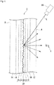
- Fig. 1 is a schematic diagram showing an example of the reflective transparent screen of the first embodiment of the present invention.
- the reflective transparent screen 1 is one having a light-scattering sheet 20 disposed between a first transparent substrate 12 and a second transparent substrate 14.
- the first transparent substrate 12 and the light-scattering sheet 20 are bonded by a first adhesive layer 16, and the second transparent substrate 14 and the light-scattering sheet 20 are bonded by a second adhesive layer 18.
- the material for the first transparent substrate 12 and the second transparent substrate 14 may be glass, a transparent resin, etc.
- the materials for the respective transparent substrates may be the same or may be different.
- the glass to constitute a transparent substrate may be soda lime glass, alkali-free glass, borosilicate glass, aluminosilicate glass, etc.
- a transparent substrate made of glass may be subjected to chemical strengthening, physical strengthening, hard coating, etc., in order to improve the durability.
- the transparent resin to constitute a transparent substrate may be a polycarbonate, a polyester (polyethylene terephthalate, polyethylene naphthalate, etc.), triacetyl cellulose, a cycloolefin polymer, polymethyl methacrylate, a fluorinated resin such as an ethylene-tetrafluoroethylene copolymer (ETFE) or polytetrafluoroethylene (PTFE), etc., and, from the viewpoint of weather resistance and transparency, preferred is a polycarbonate, a polyester or a cycloolefin polymer.
- ETFE ethylene-tetrafluoroethylene copolymer
- PTFE polytetrafluoroethylene
- the transparent substrate from the viewpoint of visibility of an image displayed on the transparent screen and visibility of a sight of the other side of the transparent screen, one having no birefringence is preferred.
- the thickness of the transparent substrate may be any thickness so long as durability as the substrate is maintained.
- the thickness of the transparent substrate may, for example, be at least 0.5 mm, at least 1 mm, or at least 2 mm. Further, the thickness of the transparent substrate may, for example, be at most 10 mm, or at most 5 mm.
- the range of the thickness may, for example, be from 0.5 to 10 mm, from 1 to 10 mm, from 2 to 10 mm, from 1 to 5 mm, from 2 to 5 mm, etc.
- the arithmetic average roughness Ra of the surface (first surface A) of the first transparent substrate 12 or the surface (second surface B) of the second transparent substrate 14 is preferably at most 0.3 ⁇ m, more preferably at most 0.05 ⁇ m.
- the image light L projected from the projector 80 is less likely to be scattered, at the first surface A or at the second surface B.
- the arithmetic average roughness Ra of the surface (first surface A) of the first transparent substrate 12 or the surface (second surface B) of the second transparent substrate 14, is preferably at least 0.001 ⁇ m from the viewpoint of efficiency for the production of the transparent substrate and costs.
- the range of Ra may, for example, be from 0.001 to 0.3 ⁇ m, from 0.001 to 0.05 ⁇ m, etc.
- the preferred range of the arithmetic average roughness Ra at the first and second surfaces of the reflective transparent screen is the same as in the case where the outermost layer is a transparent substrate.
- the first adhesive layer 16 and the second adhesive layer 18 may be formed by, for example, a thermoplastic resin, a thermosetting resin or an ultraviolet curable resin.
- thermoplastic resin or a thermosetting resin bonding is conducted by heat treatment.
- ultraviolet curable resin bonding is conducted by irradiation with ultraviolet light.
- the thermoplastic resin may, for example, be an ethylene-vinyl acetate copolymer, a polyvinyl butyral, a plasticized polyvinyl acetal, a plasticized polyvinyl chloride, a plasticized saturated thermoplastic polyester, a thermoplastic polyurethane, an ethylene-ethyl acrylate copolymer, etc.
- thermosetting resin may be an acrylic thermosetting resin, a thermosetting epoxy resin, a polyurethane curable resin, etc.
- the ultraviolet curable resin may be an acrylic photocurable resin, a photo-curable epoxy resin, an urethane acrylate-type photocurable resin, etc.
- each adhesive layer may be any thickness so long as functions as an adhesive layer are maintained, and, for example, it is preferably from 0.1 to 1.5 mm, more preferably from 0.3 to 1 mm.
- the light-scattering sheet 20 comprises a first transparent film 21; a first transparent layer 22 provided on the surface of the first transparent film 21 and having a concavo-convex structure on its surface; a metal thin film 23 which is formed along the concavo-convex structure side surface of the first transparent layer 22 and which transmits part of incident light; a second transparent layer 24 provided so as to cover the surface of the metal thin film 23; and a second transparent film 25 provided on the surface of the second transparent layer 24.
- the second transparent film 25 may be omitted.
- the light-scattering sheet 20 has, sequentially from the first surface A side, the first transparent film 21, the first transparent layer 22, the metal thin film 23, the second transparent layer 24, the second transparent film 25, in this order, but the disposition of the first transparent film 21 and the second transparent film 25 may be reversed.
- the first transparent film 21 and the second transparent film 25 may each be a transparent resin film or a thin glass film.
- the transparent resin to constitute the transparent resin film a polycarbonate, a polyester (polyethylene terephthalate, polyethylene naphthalate, etc.), triacetyl cellulose, a cycloolefin polymer, a polymethyl methacrylate, etc. may be mentioned.
- the thickness of the transparent film is preferably a thickness whereby a roll-to-roll process can be applied, and, for example, it is preferably from 0.01 to 0.5 mm, more preferably from 0.05 to 0.3 mm, further preferably at most 0.2 mm.
- the first transparent layer 22 and the second transparent layer 24 are each preferably a transparent resin layer. Materials for the respective transparent layers may be the same or different, but are preferably the same.
- the transparent resin to constitute the transparent resin layer preferred is cured product of a photocurable resin (acrylic resin, epoxy resin, etc.), a cured product of a thermosetting resin (acrylic resin, epoxy resin, etc.), or a thermoplastic resin (polyester resin, acrylic resin, polyolefin resin, polycarbonate resin, polyimide resin, polyethylene resin, urethane resin, ionomer resin, ethylene-vinyl acetate copolymer resin, polyvinyl butyral resin, fluorinated resin such as ETFE or PTFE, silicone resin, etc.).
- the yellow index of the transparent resin is, from the viewpoint of maintaining transparency so that the function as a window in the reflective transparent screen 1 is not impaired, preferably at most 10, more preferably at most 5.
- the yellow index may be 0.
- the thickness of the transparent layer may be any thickness so long as it can be easily formed by a roll-to-roll process, and, for example, it is preferably from 0.5 to 50 ⁇ m.
- the transmittance of the transparent layer is preferably from 50 to 100%, more preferably from 75 to 100%, further preferably from 90 to 100%.
- the arithmetic average roughness Ra of the concavo-convex structure formed on the surface of the first transparent layer 22 is preferably from 0.01 to 20 ⁇ m, more preferably from 0.01 to 10 ⁇ m, further preferably from 0.01 to 1 ⁇ m.
- the arithmetic average roughness Ra being at most 10 ⁇ m, is more preferred in that the concavo-convex structure will be unobtrusive when seeing through the sight of the other side of the reflective transparent screen 1.
- the arithmetic average roughness Ra being at least 1 ⁇ m, is preferred, since visibility of the sight of the other side of the reflective transparent screen 1 will be more increased.
- the arithmetic average roughness Ra of the concavo-convex structure is measured within a range of an optional square of vertical 50 mm and lateral 50 mm.
- the concavo-convex structure may be any of an irregular concavo-convex structure, a microlens array, a hologram, etc.
- An irregular concavo-convex structure is preferred in that the viewing angle and reflected light intensity will be good.
- the metal thin film 23 is one to transmit a part of light entered into the metal thin film 23 and to reflect another part, and is constituted by an alloy comprising Ag and at least one type of metal M selected from the group consisting of Pd, Au, Pt, Cu, Ru, Ir, Rh, Os, Bi, Nd and Ge.
- the content of Ag to the number of all metal atoms of the alloy in the metal film 23 is at least 65 atomic%.
- the metal thin film 23 in Fig. 1 has an irregular concavo-convex structure reflecting the irregular concavo-convex structure of the transparent layer.
- the alloy in the metal thin film 23 preferably contains at least two types of metal M including at least one of Nd and Ge among the above group, since it is thereby possible to make the effect of preventing deterioration to be higher.
- the proportion of Ag in the total number of metal atoms in the alloy in the metal film 23 is, from the viewpoint of improving the visibility of a projected image light, at least 65 atomic%, more preferably at least 85 atomic%, further preferably at least 95 atomic%.
- the rest is preferably occupied by at least one type of metal M.
- the upper limit of the proportion is less than 100 atomic%, preferably at most 99.9 atomic%.
- the range of the proportion for example, the range of the proportion may be from 65 to 99.9 atomic%, from 85 to 99.9 atomic%, etc.
- the content ratio of the number of atoms of metal M to the number of atoms of Ag in the alloy in the metal thin film 23 is preferably from 0.001 to 0.35, more preferably from 0.01 to 0.15. When it is at least 0.001, the effect to prevent oxidation or migration of Ag by incorporation of metal M becomes higher. When it is at most 0.35, excellent image visibility by Ag will be further improved.
- the types and contents of the atoms contained in the alloy in the metal thin film 23 are measured by using an X-ray photoelectron spectrometer.
- Metal M to be contained in the alloy in the metal film 23 is, from the viewpoint of improving the heat resistance, preferably at least one member selected from the group consisting of Au, Pd, Bi, Nd, Ge, Pt, Ru and Ir, and from the viewpoint of improving wet heat resistance, more preferably at least one member selected from the group consisting of Au, Pd, Nd, Ge, Pt and Ir. Further, as described above, an alloy containing at least two types of metal M including at least one of Nd and Ge is preferred.
- the thickness of the metal thin film 23 is preferably from 1 to 100 nm, more preferably from 4 to 25 nm, since it is thereby possible to exploit, without disturbing, the function attributable to the arithmetic average roughness Ra of the concavo-convex structure formed on the surface of the first transparent layer 22.
- the reflectance of the metal thin film 23 is, as the range in which a sufficient gain of screen is obtainable, preferably at least 5%, more preferably at least 15%, further preferably at least 25%.
- the upper limit of the reflectance may, for example, be 100%.
- the range of the reflectance may, for example, be from 5 to 100%, from 15 to 100%, from 25 to 100%, etc.
- the reflective transparent screen 1 may have a low reflective layer on the surface of the first transparent substrate 12 (first surface A). By having the low reflective layer, even in the case of image light L with a larger incident angle, reflection on the surface of the reflective transparent screen 1 is suppressed. As a result, decrease in
- transmittance is suppressed, and it is possible to further secure a screen gain. Further, variation in transmittance due to the location of the reflective transparent screen 1 (difference in angle of incidence) is suppressed, whereby it is possible to introduce image light L into the reflective transparent screen 1 evenly in a proper amount of light.
- the low reflective layer may be one wherein an antireflection film having a low reflective layer on the surface is bonded to the surface of the first transparent substrate 12 (first surface A), or may be one formed directly on the surface of the first transparent substrate 12 (first surface A). Further, in the case of omitting the first transparent substrate 12, it may be one formed directly on the surface of the first transparent film 21.
- the low reflective layer may be a single layer film having a low refractive index, a multilayer film having a plurality of dielectric films laminated, a fine concavo-convex structure, etc.
- the low reflective layer from the viewpoint of excellent antireflection effect and abrasion resistance, preferred is a multilayer film having a plurality of dielectric films laminated, and more preferred is a multilayer film wherein the outermost surface is other than an inorganic fluoride.
- the low reflective layer is preferably one wherein the outermost surface is composed of silicon oxide or aluminum oxide, more preferably one having a hydrophilic or water-repellent coating of e.g. a silane compound provided on the surface, further preferably one wherein the silane compound is a silane compound containing fluorine.
- the first transparent layer 22 may be formed on the surface of either one of the transparent substrates 12 and 14. Further, the second transparent layer 24 may be such that its surface is in contact with the other one of the transparent substrates 12 and 14. In the case where the disposition of the transparent layer 22 and the transparent layer 24 is as mentioned above, the adhesive layers 16 and 18 and the transparent films 21 and 25 are unnecessary.
- the light-scattering sheet 20 may be produced, for example, by forming the first transparent layer 22 on the first transparent film 21 by an imprinting method using a mold having a concavo-convex structure formed on the surface, then forming the metal thin film 23 by vapor depositing a metal on the surface of the first transparent layer 22 by physical vapor deposition, and by forming the second transparent layer 24 and the second transparent film 25 by conventional methods.
- a chemical vapor deposition (CVD) method, or a sputtering method which is included in the physical vapor deposition (PVD) method may also be used.
- the sum of the haze and diffuse reflectance of the reflective transparent screen 1 is from 10 to 90%, preferably from 20 to 70%, more preferably from 30 to 50%.
- the sum of the haze and diffuse reflectance is at least 10%, it is possible to secure the screen gain and viewing angle.
- the sum of the haze and diffuse reflectance is at most 90%, it is possible to prevent such a phenomenon that the entire reflective transparent screen 1 looks turbid.
- the contrast of a sight visible on the other side of the reflective transparent screen 1 as viewed from the observer X side will be improved, and thus, the visibility of the sight will be improved.
- the contrast of an image displayed on the reflective transparent screen 1 will be improved and thus, the visibility of the image will be improved.
- the haze of the reflective transparent screen 1 is preferably from 0 to 50%, more preferably from 0 to 15%, further preferably from 0 to 10%. When the haze is at most 50%, the visibility of a sight visible on the other side of the reflective transparent screen 1 as viewed from the observer X side will be further improved.
- the haze of the reflective transparent screen 1 is measured with respect to light incident from the second surface B side and transmitted to the first surface A side.
- the diffuse reflectance of the reflective transparent screen 1 is preferably at least 5%, more preferably at least 15%, further preferably at least 30%, still further preferably at least 50%. When the diffuse reflectance is at least 5%, it is possible to further secure the screen gain.
- the diffuse reflectance of the reflective transparent screen 1 is preferably at most 90%, more preferably at most 80%. When the diffuse reflectance is at most 90%, the visibility of a sight visible on the other side of the reflective transparent screen 1 as viewed from the observer X side can be further improved.
- the range of the diffuse reflectance may, for example, be from 5 to 90%, from 5 to 80%, from 15 to 90%, from 15 to 80%, from 30 to 90%, from 30 to 80%, from 50 to 90%, from 50 to 80%, etc.
- the diffuse reflectance of the reflective transparent screen 1 is measured with respect to light incident from the first surface A side and reflected to the first surface A side.
- the total light transmittance of the reflective transparent screen 1 is preferably from 10 to 90%, more preferably from 15 to 80%, further preferably from 25 to 75%. When the total light transmittance is at least 10%, visibility of a sight visible on the other side of the reflective transparent screen 1 as viewed from the observer X side will be excellent. When the total light transmittance is at most 90%, it is possible to secure the screen gain.
- the total light transmittance of the reflective transparent screen 1 is measured with respect to light incident from the second surface B side and transmitted to the first surface A side.
- the total light reflectance of the reflective transparent screen 1 is preferably from 5 to 90%, more preferably from 10 to 80%, further preferably from 20 to 70%. When the total light reflectance is at least 5%, it is possible to further secure the screen gain. When the total light reflectance is at most 70%, visibility of a sight visible on the other side of the reflective transparent screen 1 as viewed from the observer X side can be further improved.
- the total light reflectance of the reflective transparent screen 1 is measured with respect to light incident from the first surface A side and reflected to the first surface A side.
- the surface reflectance at the first surface A of the reflective transparent screen 1 is, with a view to sufficiently suppressing formation of double images, preferably at most 2%, more preferably at most 1%, further preferably at most 0.5%.
- the reflectance may be 0%.
- the refractive index difference between layers adjacent in the reflective transparent screen 1 is preferably within 0.2 with a view to suppressing the reflectance at each layer interface to be within 0.5%, and more preferably within 0.1 with a view to bringing the reflectance at each layer interface to be within 0.1%.
- the refractive index difference may be zero.
- Fig. 1 is a schematic diagram showing an example of an image display system having the reflective transparent screen of the first embodiment of the present invention.
- the image display system comprises the reflective transparent screen 1 and a projector 80 disposed in a space on the first surface A side of the reflective transparent screen 1.
- the projector 80 may be any projector so long as it can project image light L on the reflective transparent screen 1.
- the projector 80 may be a known projector, etc.
- a short focus projector is preferred from such a viewpoint that it is possible to project image light L from a short distance of from 10 to 90 cm, space saving for the image display system can be done, and it is possible to project image light L with a large incident angle, and it is difficult for a person to traverse the space between the projector 80 and the reflective transparent screen 1.
- image light L projected from the projector 80 and incident from the first surface A of the reflective transparent screen 1 is reflected and diffused at an irregular concavo-convex structure of the metal thin film 23 to form an image, which is visibly displayed as an image to the observer X who is on the same side as the projector 80.
- the metal thin film 23 of the reflective transparent screen 1 has a property to block at least part of the electromagnetic waves in a wavelength range longer than the visible light. By utilizing this property, it is also possible to use the reflective transparent screen as an electromagnetic wave shield.
- the reflective transparent screen 1 of the first embodiment of the present invention as described above, it is possible to transmit light, and thus it is possible to see-through a sight of the other side of the reflective transparent screen 1 as viewed from the observer. Further, since the reflective transparent screen 1 has a metal thin film 23, in such a state that the projector 80 is projecting image light L, an image displayed on the reflective transparent screen 1 can be viewed from the observer.
- the thin metal film 23 of the reflective transparent screen 1 by doping a specific metal M, deterioration due to oxidation or migration of silver as the main material of the metal thin film 23 is suppressed.
- a noble metal such as Pd, Au, Pt, Cu, Ru, Ir, Rh or Os is less likely to be combined with water or oxygen, whereby taking in (or introduction) of water or oxygen into a Ag film by metal M is less likely, and thus, it is considered that the effect to suppress deterioration due to oxidation or migration of Ag is increased.
- Bi when Bi is added, a Bi-rich layer will be formed on the outermost surface, and this will be oxidized, whereby it is believed that oxygen diffusion into the Ag film will be less.
- deterioration of Ag is suppressed by doping the metal M, whereby it is possible to prevent deterioration of image visibility, light transmittance and outer appearance of the reflective transparent screen 1.
- a transparent resin is usually used as the transparent layer 22 or 24
- water contained in the transparent resin is likely to diffuse into the Ag layer, whereby deterioration due to oxidation or migration of Ag used to be likely to occur, but in the case of the metal thin film 23 of the reflective transparent screen 1, it is possible to use a transparent resin which is usually likely to contain water, as the transparent layers 22 and 24 in contact with the metal thin film 23.
- the metal thin film is formed on the surface of a transparent layer 22 having a concavo-convex structure
- the transparent layer 22 since the transparent layer 22 has a surface area due to irregularities, the amount of adsorbed water on the transparent layer 22 surface tends to be large, whereby at the time of forming an Ag film thereon, in the film growth process, Ag is considered to be susceptible to oxidation.
- doping the metal M it is possible to prevent the oxidation deterioration in the Ag film growth process.
- the light-scattering sheet 20 is sandwiched between the first transparent substrate 12 and the second transparent substrate 14 made of glass, and they are bonded and subjected to heat treatment to prepare a laminated glass, it is possible to suppress the deterioration due to oxidation or migration of silver as the main material of the metal thin film 23. This effect becomes particularly remarkable when sandwiching the light-scattering sheet 20 via the adhesive layer 16 and adhesive layer 18, respectively, between the first transparent substrate 12 and the second transparent substrate 14.
- the specific metal M as described above, deterioration of the metal thin film 23 due to moisture emitted from the transparent resin or adhesive layer by heat treatment, is prevented.
- the first transparent substrate 12, the second transparent substrate 14, the first adhesive layer 16 and the second adhesive layer 18 provided in the reflective transparent screen 1 as described above, are not essential members of a reflective transparent screen of the present invention.
- a light-scattering sheet 20 excluding these members may be made to be a reflective transparent screen of the present invention.
- the reflective transparent screen of the second embodiment of the present invention is a reflective transparent screen having a first surface and a second surface on the opposite side thereof, which transmits either one or both of the sight of the first surface side and the sight of the second surface side to be seen through to an observer on the opposite surface side to that surface, and also displays an image light projected from the first surface side visibly as an image to an observer on the first surface side, and which has a thin metal film.
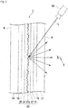
- Fig. 2 is a schematic diagram showing an example of the reflective transparent screen of the second embodiment of the present invention.
- the construction of the reflective transparent screen of the second embodiment is similar to the construction of the reflective transparent screen of the first embodiment.
- components of the construction of the second embodiment which are different from the construction of the first embodiment will be described, and the same components are identified by the same reference numerals and their description will be omitted.
- a metal thin film 23a is one to transmit a part of light entered into the metal thin film 23a and to reflect a part of the rest, and is constituted by an alloy of Ag and at least one type of metal other than Ag (hereinafter referred to as metal M'), wherein the content of Ag to the entire mass of the alloy is from 70 to 95 mass%.
- the content of the metal M' to the entire mass of the alloy is preferably from 5 to 30 mass%. That is, it is preferred that the rest other than Ag in the alloy is constituted by metal M'.
- Types and contents of the atoms contained in the alloy are measured by using an X-ray photoelectron spectrometer.
- Metal M' is preferably one such that the color of reflected light of a thin film of a simple substance of the metal M', formed on a glass substrate having a thickness of (1.1 ⁇ 0.3) mm (one having a refractive index of helium lamp d line (587.56 nm) of 1.589 and an Abbe number of 33) in such a film thickness that the visible light transmittance including the glass substrate would be (60 ⁇ 1.5)%, would be x ⁇ 0.35 and y ⁇ 0.35 by chromaticity coordinates (x, y) of the XYZ color system (JIS Z8701; 1999). It is preferred that the glass substrate is a soda lime glass substrate.
- the reason for specifying the range of the thickness of the glass substrate is that it is sometimes difficult to prepare the glass substrate to be exactly 1.1 mm. Chromaticity coordinates of the reflected lights of the thin films formed on glass substrates different in thickness within the above range are almost the same.
- the reason for specifying the range of the visible light transmittance is that it is sometimes difficult to form a film to have such a thickness that the visible light transmittance becomes exactly 60%. Chromaticity coordinates of the reflected lights of the thin films different in thickness in the above range, are almost the same.
- x is preferably at least 0.25 and at most 0.33, more preferably at least 0.28 and at most 0.32.
- y is preferably at least 0.25 and at most 0.34, more preferably at least 0.29 and at most 0.33.
- the above-mentioned preferred x and y may be optionally combined.
- the combination may, for example, be such that x is from 0.25 to 0.33 and y is from 0.25 to less than 0.34; x is from 0.25 to 0.33 and y is from 0.29 to 0.33; x is from 0.28 to 0.32 and y is from 0.25 to less than 0.34; x is from 0.28 to 0.32 and y is from 0.29 to 0.33; etc.
- the metal M' may be one such that the chromaticity coordinates of the color of reflected light of a thin film of the metal simple substance (the film thickness thereof is such a thickness that visible light transmittance including the glass substrate would be (60 ⁇ 1.5)%) satisfy the above-mentioned range, among metals in Group 1 elements to Group 16 elements of the periodic table.
- an alkali metal such as K, Rb, etc.
- a transition metals such as Sc, Y, Ti, Zr, Hf, V, Nb, Ta, Cr, Mo, W, Mn, Re, Ir, Ni, Pd, Cu, Zn, Cd, Nd, Bi, Ge, etc.
- Al, In, etc. may be mentioned.
- metals of Group 3 elements to Group 16 elements of the periodic table are preferred, since they are less likely to react with water than the alkali metals and alkaline earth metals, and higher durability can be obtained.
- at least one member selected from Zn, Pd, In, W and Mo is more preferred. With the above preferred metal M', the color tone of reflected light of the Ag thin film will be improved, and a metal thin film 23a having a high visible light reflectance can be easily obtained.
- the metal M' is at least one member selected from Nd, Bi and Ge, since it is possible to obtain, in addition to high visible light transmittance, a reflective layer 23a having a high heat resistance easily.
- the metal M' is at least one member selected from Zn, Pd, In, W and Mo
- a thin film of simple substance of that metal is formed in a thickness of e.g. from 1 to 100 nm on a glass substrate with a thickness of (1.1 ⁇ 0.3) mm
- the visible light transmittance of the thin film of the metal simple substance including the glass substrate will be (60 ⁇ 1.5)%.
- the glass substrate is preferably a soda lime glass substrate.
- the metal M' is particularly preferably Pd and/or Zn.
- the metal thin film 23a is made of an alloy having such metal M' combined with Ag, it is possible to improve the heat resistance of the metal film 23a.
- the heat treatment is conducted at from 120 to 140°C for from 1 to 2 hours.
- An Ag film having no metal M' is susceptible to deterioration (migration occurs and transmittance changes) or discoloration by the heat treatment, but the metal thin film 23a is an alloy of Ag and the metal M', whereby heat resistance is improved.
- the metal thin film 23a is an alloy of Ag and the metal M', whereby heat resistance is improved.
- the color tone of reflected light of the Ag thin film will be improved, and a metal thin film 23a having high visible light reflectance can be easily obtained.
- the alloy is one such that the visible light reflectance of the thin film of the alloy formed on a glass substrate having a thickness of (1.1 ⁇ 0.3) mm (one having a refractive index of helium lamp d line (587.56 nm) of 1.589 and an Abbe number of 33), in such a thickness that the visible light transmittance including the glass substrate would be at least (60 ⁇ 1.5)% (e.g. from 1 to 100 nm), would be preferably at least 15%, more preferably at least 18%.
- the upper limit of the visible light reflectance may, for example, be 38%.
- the reflective transparent screen 1 shows a high screen gain, whereby image visibility projected on the metal thin film 23a will be improved.
- the metal thin film 23a preferably has a visible light transmittance of at least 60% and a visible light reflectance of at least 15%.
- the visible light transmittance of the metal thin film 23a can be adjusted by the thickness of the metal film 23a. With a view to increasing the screen gain, it is preferred that the visible light transmittance of the metal thin film 23a is at most 85%.
- the visible light reflectance is preferably at least 15%, more preferably at least 18%.
- the thickness of the metal film 23a is preferably from 5 to 50 nm, more preferably from 10 to 35 nm, further preferably from 10 to 20 nm.
- the visible light reflectance can easily be made to be at least 15%.
- the visible light transmittance can easily be made to be at most 85%.
- the metal thin film 23a in Fig. 2 has an irregular concavo-convex structure reflecting the irregular concavo-convex structure of the transparent layer.
- the thickness of the metal film 23a is preferably from 1 to 100 nm, more preferably from 4 to 25 nm, from such a viewpoint that it is possible to utilize, without hindering, the function due to the arithmetic average roughness Ra of the irregular concavo-convex structure formed on the surface of the first transparent layer 22.
- the material, yellow index, thickness, transmittance and concavo-convex structure are the same as of the transparent layer in the reflective transparent screen 1 of the first embodiment, including preferred embodiments.
- the arithmetic average roughness Ra of the concavo-convex structure formed on the surface of the first transparent layer 22a is preferably from 0.01 to 20 ⁇ m, more preferably from 0.05 to 10 ⁇ m, further preferably from 0.1 to 1 ⁇ m.
- the arithmetic average roughness Ra of the concavo-convex structure is measured in a range of a square of vertical 50 mm and lateral 50 mm.
- the light-scattering sheet 20 of the reflective transparent screen 1 of the second embodiment can be produced in the same manner as the light-scattering sheet 20 of the reflective transparent screen 1 of the first embodiment.
- the preferred optical properties such as the haze and diffuse reflectance of the reflective transparent screen 1 of the second embodiment are the same as the preferred optical properties of the reflective transparent screen 1 of the first embodiment.
- the ratio of the diffuse reflectance to the haze is preferably at least 0.5, more preferably at least 1.
- the diffuse reflectance/haze is at least 1, as viewed from the observer X, the visibility of a sight seen on the other side of the reflective transparent screen 1 is good, and thus, it is possible to see a projected image and a sight of the other side of the reflective transparent screen 1.
- Such reflective transparent screen 1 is suitable to be utilized in an environment where ambient light is present.
- the visible light transmittance of the reflective transparent screen 1 of the second embodiment is preferably from 1 to 90%, preferably from 10 to 90%, more preferably from 15 to 80%, further preferably from 25 to 75%.
- the visible light transmittance of the reflective transparent screen 1 is measured with respect to light entered from the second surface B side and transmitted to the first surface A side.
- the visible light reflectance of the reflective transparent screen 1 of the second embodiment is preferably from 1 to 90%, more preferably from 5 to 70%, further preferably from 5 to 60%, also preferably from 20 to 90%, and from 20 to 50%.
- the visible light reflectance of the reflection type transparent screen 1 is measured with respect to light entered from the first surface A side and reflected to the first surface A side.
- Fig. 2 is a schematic diagram showing an example of an image display system having the reflective transparent screen of the second embodiment of the present invention.
- This schematic diagram and the image display method are the same as the schematic diagram and the image display method of the reflective transparent screen of the first embodiment of the present invention, and therefore, their description will be omitted here.
- the reflective transparent screen 1 of the second embodiment of the present invention as described above, it is possible to transmit light, and thus, it is possible to see-through a sight on the other side of the reflective transparent screen 1 as viewed from the observer.
- the reflective transparent screen 1 has a metal thin film 23a, whereby in such a state that a projector 80 is projecting image light L, it is possible to see an image displayed on the reflective transparent screen 1 as viewed from the observer.
- the color of reflected light of the metal thin film 23a made of an alloy of Ag and metal M' approaches the blue than the color of the reflected light of the Ag thin film. Namely, the color tone closer to yellow of the Ag thin film is shifted to the blue side.
- the color tone of the Ag thin film is improved, and excellent image reproducibility (e.g. a white color of projected image light is reflected as white reflected light) is obtainable.
- the first transparent substrate 12, the second transparent substrate 14, the first adhesive layer 16 and the second adhesive layer 18 provided in the reflective transparent screen 1 as described above, are not essential members of a reflective transparent screen of the present invention.
- a light-scattering sheet 20 excluding these members may be made to be a reflective transparent screen of the present invention.
- the reflective transparent screen of the third embodiment of the present invention is one which has a first surface and a second surface on the opposite side, and which visibly transmits either one or both of the sight of the first surface side and the sight of the second surface side to an observer on the opposite surface side to that surface, and also visibly displays image light projected from the first surface side as an image to an observer on the first surface side.
- the reflective transparent screen of the present invention has a reflective layer, a first barrier layer in contact with a first surface of the reflective layer, and a second barrier layer in contact with a second surface of the reflective layer.
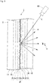
- Fig. 3 is a schematic diagram showing an example of the reflective transparent screen of the present invention.
- the reflective transparent screen 1 is one having a light-scattering sheet 20 disposed between a first transparent substrate 12 and a second transparent substrate 14.
- the first transparent substrate 12 and the light-scattering sheet 20 are bonded by a first adhesive layer 16, and the second transparent substrate 14 and the light-scattering sheet 20 are bonded by a second adhesive layer 18.
- the construction of the reflective transparent screen of the third embodiment is similar to the construction of the reflective transparent screen of the first embodiment.
- points in which the construction of the third embodiment is different from the construction of the first embodiment will be described, and the same components will be identified by the same reference numerals and their description will be omitted.
- the light-scattering sheet 20 comprises a first transparent film 21; a first transparent layer 22 provided on the surface of the first transparent film 21 and having an irregular concavo-convex structure on the surface; a first barrier layer 26 which transmits part of the incident light, formed along the surface of the concavo-convex structure side of the first transparent layer 22; a reflective layer 23b which transmits part of the incident light, formed on the surface of the first barrier layer; a second barrier layer 27 formed on the surface of the reflective layer 23b; a second transparent layer 24 provided so as to cover the surface of the second barrier layer 27; and a second transparent film 25 provided on the surface of the second transparent layer 24.
- the second transparent film 25 may be omitted.
- the light-scattering sheet 20 comprises sequentially from the first surface A side, the first transparent film 21, the first transparent layer 22, the first barrier layer 26, the reflective layer 23b, the second barrier layer 27, the second transparent layer 24 and the second transparent film 25.
- the disposition of the first transparent film 21 and the second transparent film 25 may be reversed.
- the first barrier layer 26 in contact with the first surface of the reflection layer 23b and the second barrier layer 27 in contact with the second surface of the reflective layer 23b, are ones which improve the color tone of the reflective layer 23b, and prevent its deterioration (to increase the deterioration resistance).
- Each barrier layer transmits a part of light projected towards the reflective layer 23b and reflects another part.
- the first barrier layer 26 is made of a metal thin film containing at least one type of first metal other than Ag or an alloy thereof, or an oxide film containing an oxide of the first metal.
- the second barrier layer 27 is made of a metal thin film containing at least one type of second metal other than Ag or an alloy thereof, or an oxide film containing an oxide of the second metal.
- first barrier layer 26 and the second barrier layer 27 Unless the effects of the present invention are impaired, a small amount of elements other than the first metal and the second metal may be contained in the first barrier layer 26 and the second barrier layer 27.
- the types and contents of atoms contained in the barrier layer material are measured by using an X-ray photoelectron spectrometer.
- first metal is an alloy composed of two or more metals
- second metal is an alloy composed of two or more metals
- first metal and the second metal may collectively be referred to as a barrier metal.
- first barrier layer 26 and the second barrier layer 27 may collectively be referred to as a barrier layer.
- the content of the first metal or its oxide to the entire mass of the material of the first barrier layer 26 is, each independently, preferably from 70 to 100 mass%, more preferably from 80 to 100 mass%, further preferably from 90 to 100 mass%.
- the content of the second metal or its oxide to the entire mass of the material of the second barrier layer 27 is, each independently, preferably from 70 to 100 mass%, more preferably from 80 to 100 mass%, further preferably from 90 to 100 mass %.
- the effects to improve the color tone and to improve the deterioration resistance of the reflective layer 23b by providing the barrier layer can be obtained more easily.
- the first metal or the second metal (barrier metal) to constitute the metal thin film constituting the barrier layer is one such that the color of reflected light of a thin film of the first metal simple substance or a thin film of the second metal simple substance, formed on a glass substrate in a thickness of (5 ⁇ 3) nm, i.e. from 2 to 8 nm, would be x ⁇ 0.35 and y ⁇ 0.35 by the chromaticity coordinates (x, y) of the XYZ color system (JIS Z8701; 1999).
- the above glass substrate is preferably a soda lime glass substrate.
- the reason for specifying the range of the film thickness of the thin film is that it is sometimes difficult to form the film to have a film thickness of exactly 5 nm.
- the chromaticity coordinates of reflected lights of the thin films different in thickness in the above range, are almost the same.
- x is preferably from 0.25 to 0.34, more preferably from 0.27 to 0.33, further preferably from 0.28 to 0.32.
- y is preferably from 0.25 to less than 0.35, more preferably from 0.27 to less than 0.35, further preferably from 0.28 to 0.34.
- the above preferred x and y may be optionally combined.
- the combination may, for example, be such that x is from 0.25 to 0.34 and y is from 0.25 and less than 0.35; x is from 0.25 to 0.34 and y is from 0.27 to less than 0.35; x is from 0.25 to 0.34 and y is from 0.28 to 0.34; x is from 0.27 to 0.33 and y is from 0.25 to less than 0.35; x is from 0.27 to 0.33 and y is from 0.27 to less than 0.35; x is from 0.27 to 0.33 and y is from 0.28 to 0.34; x is from 0.28 to 0.32 and y is from 0.25 to less than 0.35; x is from 0.28 to 0.32 and y is from 0.27 to less than 0.35; x is from 0.28 to 0.32 and y is 0.28 to 0.34; etc.
- the barrier layer exhibits a color tone closer to blue.
- barrier layers are provided on both sides of the reflective layer 23b, it is possible to easily improve the color tone close to yellow of the reflective layer 23b.
- An oxide of the first metal or an oxide of the second metal (oxide of the barrier metal) to constitute the oxide film constituting the barrier layer is one such that the color of reflected light of its thin film formed on a glass substrate in a film thickness of (5 ⁇ 3) nm, i.e. from 2 to 8 nm, would be x ⁇ 0.35 and y ⁇ 0.35 by the chromaticity coordinates (x, y) of the XYZ color system (JIS Z8701; 1999).
- the above glass substrate is preferably a soda lime glass substrate.
- the reason for specifying the range of the film thickness of the thin film is that it is sometimes difficult to form the film to have a thickness of exactly 5 nm.
- the chromaticity coordinates of reflected lights of the thin films different in thickness in the above range are almost the same.
- x is preferably from 0.25 to 0.34, more preferably from 0.27 to 0.33, further preferably from 0.28 to 0.32.
- y is preferably from 0.25 to 0.34, more preferably from 0.27 to 0.34, further preferably from 0.28 to 0.34.
- the above preferred x and y may be optionally combined.
- the combination may, for example, be such that x is from 0.25 to 0.34 and y is from 0.25 to 0.34; x is from 0.25 to 0.34 and y is from 0.27 to 0.34; x is from 0.25 to 0.34 and y is from 0.28 to 0.34; x is from 0.27 to 0.33 and y is from 0.25 to 0.34; x is from 0.27 to 0.33 and y is from 0.27 to 0.34; x is from 0.27 to 0.33 and y is from 0.28 to 0.34; x is from 0.28 to 0.32 and y is 0.25 to 0.34; x is from 0.28 to 0.32 and y is from 0.27 to 0.34; x is from 0.28 to 0.32 and y is from 0.28 to 0.34; etc.
- the barrier layer exhibits a color closer to blue.
- barrier layers are provided on both sides of the reflective layer 23b, it is possible to easily improve the color tone close to yellow of the reflective layer 23b.
- the barrier metal may be one such that the chromaticity coordinates of the color of reflected light of a thin film (film thickness: (5 ⁇ 3) nm) made of the metal simple substance, satisfy the above-mentioned range.
- an alkali metal such as K, Rb, etc.
- a transition metal such as Sc, Y, Ti, Zr, Hf, V, Nb, Ta, Cr, Mo, W, Mn, Re, Ir, Ni, Pd, Cu, Zn, Cd, etc.
- Al, In, etc. may be mentioned.
- barrier metals metals in Group 3 elements to Group 16 elements in the periodic table are preferred in that they are less likely to react with water than alkali metals and alkaline earth metals, and the higher durability can be obtained. Further, among the above barrier metals, at least one member selected from Zr, Ni, Cr, Ti, Zn, Nb, Zn, Pd, In, W and Mo is more preferred.
- the barrier layer exhibits a proper bluish color tone, whereby it is possible to readily obtain a reflective transparent screen 1 having the color tone improved and having a high visible light reflectance.
- the barrier metal or its oxide Zr, NiCr, TiO 2 +ZnO or Nb 2 O 5 is particularly preferred.
- the barrier layer is composed of such a barrier metal, the effects to improve the color tone of the barrier layer and the reflective layer 23b and to improve the resistance to deterioration will be further excellent.
- the heat treatment is conducted at 120 to 140°C for 1 to 2 hours.
- An Ag thin film having no barrier layer is likely to undergo discoloration and deterioration (migration occurs whereby transmittance changes) by the heat treatment.
- the barrier layer prevents contact between the reflective layer 23b and moisture or oxygen, whereby the deterioration resistance of the reflective layer 23b will be improved.
- the color tone will be improved, and a reflective transparent screen 1 having a high visible light reflectance can be easily obtained.
- composition of the first barrier layer and the composition of the second barrier layer may be the same or may be different.
- the thickness of the barrier layer is preferably adjusted, for example, in a range of from 1 to 70 nm with a view to balancing the visible light transmittance and the visible light reflectance.
- the thickness of the barrier layer is preferably, for example, from 1 to 60 nm, more preferably from 1 to 10 nm, further preferably from 1 to 5 nm.
- the barrier layer is constituted by an oxide of the barrier metal, it is preferably from 1 to 60 nm, more preferably from 5 to 60 nm, further preferably from 10 to 60 nm.
- the thickness of the first barrier layer 26 and the thickness of the second barrier layer 27 may be the same or different.
- the thicknesses are different, so long as x and y of the chromaticity coordinates, respectively, satisfy x ⁇ 0.35 and y ⁇ 0.35
- the thickness of one barrier layer may be from 5 to 20 nm
- the thickness of the other barrier layer may be from 50 to 70 nm. In this way, it is easy to improve and adjust the color tone.
- the thickness of the barrier layer is at least 1 nm as mentioned above, it is possible to easily improve the color tone of the reflective transparent screen 1, and further to prevent the deterioration due to oxidation, etc. of the reflective layer 23b.
- the thickness of the barrier layer is at most 60 nm as mentioned above, it is possible to further increase the visible light transmittance of the barrier layer.
- the thickness of the first barrier layer and the thickness of the second barrier layer may be the same or different.
- the barrier layers are oxide films made of an oxide of the barrier metal, it is preferred that the barrier layer on the side opposite to the barrier layer on the incident side of image light, is thicker, since it is thereby possible to better improve the color tone of the reflective layer 23b.
- the reflective layer 23b is one which transmits a part of light entered into the reflective layer 23b and reflects another part, and which is constituted by Ag alone, or an alloy of Ag and at least one type of third metal other than Ag.
- the content of Ag to the entire mass of metals constituting the reflective layer 23b is from 70 to 100 mass%.
- the content of Ag in the case where the metal constituting the reflective layer 23b is an alloy, is preferably from 70 to 99.9 mass%, more preferably from 70 to 95 mass%.
- the content of the third metal to the entire mass of metals constituting the reflective layer 23b is preferably from 0 to 30 mass%.
- the content of the third metal to the entire mass of metals constituting the reflective layer 23b is, for example, from 5 to 30 mass%. It is preferred that the rest of the metal, other than Ag, constituting the reflecting layer 23b, is constituted by the third metal.
- a small amount of elements other than the third metal may be contained in the metal constituting the reflective layer 23b.
- the types and contents of atoms contained in the material of the reflective layer 23b are measured by using an X-ray photoelectron spectrometer.
- the reflective layer 23b is covered by the barrier layers, so that the contact between the reflective layer 23b and water or oxygen is prevented, whereby the reflective layer 23b is in a state less likely to be deteriorated. Further, migration of Ag constituting the reflective layer 23b is also suppressed. Therefore, deterioration resistance of the metal constituting the reflective layer 23b protected by the barrier layers may be high or may be low. Thus, by using Ag with a low resistance to deterioration as the main material of the reflective layer 23b, it is possible to obtain a reflective transparent screen 1 of laminated glass having excellent optical characteristics utilizing the characteristic of high reflectance which Ag has.
- the third metal is preferably at least one member selected from the group consisting of Pd, Au, Pt, Cu, Ru, Ir, Rh, Os and Bi, and from the viewpoint of increasing the visible light reflectance of the reflective layer 23b, the third metal is more preferably Au.
- the reflective layer 23b is covered by the barrier layers.
- the third metal is preferably one such that the color of reflected light of a thin film of the third metal simple substance formed on a glass substrate having a thickness of 1.1 ⁇ 0.3 mm (one having a refractive index of helium lamp d line (587.56 nm) of 1.589 and an Abbe number of 33), in such a film thickness that the visible light transmittance including the glass substrate, would be (60 ⁇ 1.5)%, would be x ⁇ 0.37 and y ⁇ 0.37 by the chromaticity coordinates (x, y) of the XYZ color system (JIS Z8701; 1999).
- the reason for specifying the range of the thickness of the glass substrate is that it is sometimes difficult to prepare the glass substrate to be exactly 1.1 mm.
- the chromaticity coordinates of reflected lights of the thin films formed on glass substrates different in thickness within the above range are almost the same.
- the measurement of the color of reflected light is carried out by painting the surface of the glass substrate on the side where the reflective layer 23b is not formed, with a black color in order to prevent the influence of reflected light of the glass substrate.
- the reason for specifying the range of the visible light transmittance is that it is sometimes difficult to form the film having such a film thickness that the visible light transmittance becomes exactly 60%.
- the chromaticity coordinates of reflected lights of the thin films different in thickness in the above range are almost the same.
- x is preferably from 0.25 to 0.34, more preferably from 0.30 to 0.33, further preferably from 0.29 to 0.32.
- y is preferably from 0.25 to 0.36, more preferably from 0.30 to 0.35, further preferably from 0.31 to 0.34.
- the above preferred x and y may be optionally combined.
- the combination may, for example, be such that x is from 0.25 to 0.34 and y is from 0.25 to 0.36; x is from 0.25 to 0.34 and y is from 0.30 to 0.35; x is from 0.25 to 0.34 and y is from 0.31 to 0.34; x is from 0.30 to 0.33 and y is from 0.25 to 0.36; x is from 0.30 to 0.33 and y is from 0.30 to 0.35; x is from 0.30 to 0.33 and y is from 0.31 to 0.34; x is from 0.29 to 0.32 and y is from 0.25 to 0.36; x is from 0.29 to 0.32 and y is from 0.30 to 0.35; x is from 0.29 to 0.32 and y is from 0.31 to 0.34, etc.
- a specific third metal may, for example, be one such that, among metals in Group 1 elements to Group 16 elements in the periodic table, the chromaticity coordinates of the color of reflected light of a thin film of the metal simple substance formed on a glass substrate having a thickness of (1.1 ⁇ 0.3) mm (one having a refractive index of helium lamp d line (587.56 nm) of 1.589, and an Abbe number of 33), in such a film thickness that the visible light transmittance including the glass substrate would be (60 ⁇ 1.5)%, satisfy the above range.
- alkali metal such as K, Rb, etc.
- a transition metal such as Sc, Y, Ti, Zr, Hf, V, Nb, Ta, Cr, Mo, W, Mn, Re, Ir, Ni, Pd, Au, Cu, Zn, Cd, Nd, Bi, Ge, etc.; Al, In, etc.
- the third metal is preferably a metal of Group 3 elements to Group 16 elements of the periodic table, since the higher durability can thereby be obtained. Further, among the above, the third metal is more preferably at least one member selected from Au, Zn, Pd, In, W and Mo from the viewpoint that it is easy to form an alloy with Ag. When the third metal is as mentioned above, a reflective layer 23b having a high visible light reflectance can be easily obtained, and it is possible to easily improve the color tone of reflected light of the reflective layer 23b by the barrier layers.
- the third metal is at least one member selected from Nd, Bi and Ge, it is possible to readily obtain a reflection layer 23b having high heat resistance in addition to a high visible light transmittance, such being particularly preferred.
- the third metal is at least one member selected from Au, Zn, Pd, In, W, Mo, Nd, Bi and Ge
- the visible light transmittance of the thin film including the glass substrate would be (60 ⁇ 1.5)%.
- the glass substrate is preferably a soda lime glass substrate.
- the alloy has the above-mentioned composition, the color tone of reflected light of the Ag thin film will be improved, and a reflective layer 23b having a high visible light reflectance can be easily obtained.
- the alloy to constitute the reflective layer 23b is formed into a film on a glass substrate having a thickness of (1.1 ⁇ 0.3) mm (one having a refractive index of helium lamp d line (587.56 nm) of 1.589, and an Abbe number of 33) in such a thickness that the visible light transmittance including the glass substrate would be (60 ⁇ 1.5)% (e.g. from 1 to 100 nm), one having a higher visible light reflectance is better.
- the visible light reflectance is, for example, preferably at least 15%, more preferably at least 25%, further preferably at least 30%.
- As the upper limit value of the visible light reflectance for example, 38% may be mentioned.
- the reflective transparent screen 1 When an alloy whereby the above visible light reflectance would be at least 15%, is used, the reflective transparent screen 1 will exhibit a high screen gain, and the image visibility of image light projected to the reflective layer 23b will be improved.
- the reflective layer 23b in Fig. 3 and the first barrier layer 26 and the second barrier layer 27 provided on both sides thereof, have an irregular concavo-convex structure reflecting the irregular concavo-convex structure of the transparent layers.
- the thickness of the reflective layer 23b is preferably from 1 to 100 nm, more preferably from 5 to 50 nm, further preferably from 10 to 35 nm, particularly preferably from 10 to 20 nm, from such a viewpoint that it is possible to utilize, without hindering, the function due to the arithmetic average roughness Ra of the irregular concavo-convex structure formed on the surface of the first transparent layer 22.
- the thickness of the reflective layer 23b is at least 1nm as mentioned above, it is possible to increase the visible light reflectance and thereby to improve the visibility of an image projected on the reflective transparent screen 1 (i.e. to increase the screen gain).
- the thickness of the reflective layer 23b is at most 100 nm as mentioned above, it is possible to prevent the visible light transmittance from becoming too low, and to easily see a sight of the other side of the reflective transparent screen 1 as viewed from the observer.
- the multi-layer structure having the first barrier layer 26, the reflective layer 23b and the second barrier layer 27 laminated in this order, on a glass substrate having a thickness of (1.1 ⁇ 0.3) mm (one having a refractive index of helium lamp d line (587.56 nm) of 1.589, and an Abbe number of 33), preferably exhibits a visible light transmittance of (60 ⁇ 1.5)% and a visible light reflectance of at least 15%.
- the visible light reflectance is more preferably at least 25%, further preferably at least 30%.
- the upper limit value of the visible light reflectance for example, 38% may be mentioned.
- the visible light transmittance includes the effect of the glass substrate.
- the reflective layer 23b and the second barrier layer 27 used in the above multi-layer structure having a high visible light reflectance are used in the reflective transparent screen 1, the visibility of an image projected to the reflective transparent screen 1 will be improved (the screen gain will be increased), such being preferred.
- the visible light transmittance of the above multilayer structure having the first barrier layer 26, the reflective layer 23b and the second barrier layer 27 laminated on the glass substrate to constitute the reflective transparent screen 1, is preferably at most 85%.
- the visible light transmittance includes the effect of the glass substrate.
- the visible light transmittance of the multilayer structure or the reflective transparent screen 1 can be adjusted by the thicknesses of the reflective layer 23b and the respective barrier layers.
- the material, the yellow index, the thickness, the transmittance and the concavo-convex structure are the same as the transparent layer of the reflective transparent screen 1 of the first embodiment, including preferred embodiments.
- the arithmetic average roughness Ra of the concavo-convex structure formed on the surface of the first transparent layer 22a is preferably from 0.01 to 20 ⁇ m, more preferably from 0.05 to 10 ⁇ m, further preferably from 0.1 to 1 ⁇ m.
- the arithmetic average roughness Ra of the concavo-convex structure is measured in a range of any optional square of vertical 50 mm and lateral 50 mm.
- the reflective transparent screen 1 of the third embodiment may have a low reflective layer on the surface of the first transparent substrate 12 (first surface A).
- the low reflective layer is the same as the low reflective layer of the reflective transparent screen 1 of the first embodiment, and therefore, its description will be omitted here.
- the light-scattering sheet 20 may be produced, for example, by forming the first transparent layer 22 by an imprinting method using a mold having an irregular concavo-convex structure formed on the surface, vapor-depositing metals on the surface of the first transparent layer 22 by a physical vapor deposition method to form the first barrier layer 26, the reflective layer 23b and the second barrier layer 27, and forming by conventional methods, the second transparent layer 24, the first transparent film 21 and the second transparent film 25.
- a chemical vapor deposition (CVD) method or a sputtering method included in a physical vapor film deposition (PVD) method, may also be used.
- the first transparent layer 22 may be formed on the surface of either one of the transparent substrates 12 and 14.
- the second transparent layer 24 may be such that its surface is in contact with the other one of the transparent substrates 12 and 14. In such a case, the adhesive layers 16 and 18 and the transparent films 21 and 25 are not necessary. (Optical properties of reflective transparent screen)
- the preferred optical properties such as the haze, diffuse reflectance, etc. of the reflective transparent screen 1 of the third embodiment are the same as the preferred optical properties of the reflective transparent screen 1 of the first embodiment, and therefore, their description will be omitted here.
- the ratio of the diffuse reflectance to the haze is the same as the (diffuse reflectance/haze) in the second embodiment, and therefore, its description will be omitted here.
- the visible light transmittance and the visible light reflectance of the reflective transparent screen 1 of the third embodiment are the same as the visible light transmittance and the visible light reflectance of the reflective transparent screen 1 of the second embodiment, and therefore, their description will be omitted here.
- the reflectance of the surface at the first surface A of the reflective transparent screen 1 is, with a view to sufficiently preventing formation of double images, preferably at most 2%, more preferably at most 1%, further preferably at most 0.5%.
- the reflectance may be 0%.
- the difference in refractive index between adjacent layers in the reflective transparent screen 1 is, from such a viewpoint that the reflectance at the interface of the respective layers can be suppressed within 0.5%, preferably within 0.2, and from such a viewpoint that the reflectance at the interface of the respective layers can be made to be about 0.1%, more preferably within 0.1.
- the difference in refractive index may be 0.
- Fig. 3 is a schematic diagram showing an example of an image display system having the reflective transparent screen of the third embodiment of the present invention.
- This schematic diagram and the image display method are the same as the schematic diagram of the reflective transparent screen of the first embodiment of the present invention and the image display method thereof, and therefore, their description will be omitted here.
- the reflective transparent screen 1 of the third embodiment of the present invention as described above, it is possible to transmit light, and thus, it is possible to see-through a sight of the other side of the reflective transparent screen 1 as viewed from the observer.
- the reflective transparent screen 1 has a reflective layer 23b, whereby in such a state that image light L is projected from the projector 80, it is possible to see an image displayed on the reflective transparent screen 1 as viewed from the observer.
- the color tone of reflected light of the reflective layer 23b is offset by the color tones of the barrier layers 26 and 27, whereby it is possible to obtain excellent image reproducibility.
- the reflective layer 23b is the Ag thin film, and may be similarly exhibited also in a case where the reflective layer 23b is made of an alloy of Ag and a third metal. Namely, the color tone close to yellow of the reflective layer 23b based on Ag will be shifted to the blue side by the barrier layers, whereby the color tone of the reflective layer 23b will be improved, and excellent image reproducibility will be obtained. Since it is thereby easy to adjust the color tone, the reflective layer 23b is preferably a metal thin film made of an alloy of Ag and a third metal.
- both sides of the reflection layer 23b are covered by barrier layers, whereby oxygen or moisture is less likely to contact the reflective layer 23b, and oxidation or migration of Ag constituting the reflective layer 23b is prevented.
- barrier layers whereby oxygen or moisture is less likely to contact the reflective layer 23b, and oxidation or migration of Ag constituting the reflective layer 23b is prevented.
- the reflective layer 23b since the reflective layer 23b is thus protected by the barrier layers, the reflective layer 23b itself may not be constituted by a material having high heat resistance. Therefore, the reflective layer 23b may be an Ag thin film consisting solely of Ag or may be a metal thin film made of an alloy of Ag and a third metal. As the reflective layer 23b contains Ag as the main material, the reflective transparent screen 1 will be one having excellent optical properties with high reflectance.
- the reflective layer 23b is protected by the barrier layers, it is possible to provide, in contact with the barrier layers, transparent layers 22 and 24 made of a transparent resin which is likely to contain a moisture.
- transparent layers 22 and 24 made of a transparent resin it is possible to obtain a reflective transparent screen 1 which is excellent in optical properties such as transmittance, reflectance, etc. of light, and which is light in weight and thin in thickness.
- the reflective layer 23b in the present invention is provided with the barrier layers on both sides, whereby the oxidation of the reflective layer 23b is prevented, and thus, it is possible to adopt such a construction that the reflective layer 23b is sandwiched by transparent layers 22 and 24 made of a transparent resin, via the barrier layers.
- the first transparent substrate 12, the second transparent substrate 14, the first adhesive layer 16 and the second adhesive layer 18, provided in the reflective transparent screen 1 as described above, are not essential members of a reflective transparent screen of the present invention.
- a light-scattering sheet 20 excluding these members may be used as a reflective transparent screen of the present invention.
- first transparent film provided with a first transparent layer (thickness: 7 ⁇ m) having an irregular concavo-convex structure on the surface.
- the PET film provided with the first transparent layer was placed in a vacuum chamber of a magnetron sputtering apparatus, the degree of vacuum in the vacuum chamber was made to be at most 1.0 ⁇ 10 -4 Pa, and then, highly pure Ar gas (purity: 99.99 vol%) was introduced to 1.0 ⁇ 10 -1 Pa.
- highly pure Ar gas purity: 99.99 vol%
- an electric power was applied to the sputter target to form an Ag film (thickness: 12 nm) containing Au, as a metal thin film on the surface of the irregular concavo-convex structure of the first transparent layer.
- the composition of the metal thin film was analyzed by an X-ray photoelectron spectrometer as shown below, whereby the proportion of Au was 4 atomic%.
- an UV curable resin was applied by die coating, and another PET film (thickness: 75 ⁇ m) (second transparent film) was overlaid thereon. UV light of 1,000 mJ was radiated from the side of another PET film, to form a second transparent layer (thickness: 7 ⁇ m) made of the cured UV curable resin.
- a light-scattering sheet (reflective transparent screen) having a laminated structure of (PET film/first transparent layer with irregular concavo-convex surface/Ag film (metal thin film) containing 4 atomic% of Au/second transparent layer/PET film) was obtained.
- a light-scattering sheet was obtained in the same manner as in Example 1A except that sputtering was conducted by using a target different in the Au content of 3 atomic% or 1 atomic% to obtain an Ag film containing 2 atomic% or 1 atomic% of Au.
- a light-scattering sheet was obtained in the same manner as in Example 1A except that sputtering was conducted by using an Ag target containing 5 atomic% of Bi, to form an Ag film containing 4 atomic% of Bi.
- a light-scattering sheet was obtained in the same manner as in Example 1A except that sputtering was conducted by using an Ag target containing 1 atomic% of Bi, 0.2 atomic% of Nd and 1 atomic% of Ge, to form an Ag film (thickness: 10 nm) containing 1 atomic% of Bi, 0.2 atomic percent of Nd and 1 atomic% of Ge.
- a light scattering sheet was obtained in the same manner as in Example 1A except that sputtering was conducted by using an Ag target containing from 10 atomic% to 1 atomic% of Pd, to form an Ag film different in the Pd content of from 10 atomic% to 1 atomic%.
- a light-scattering sheet was obtained in the same manner as in Example 1A except that sputtering was conducted by using a pure Ag target having no other metal added, to form a pure Ag film.
- a light-scattering sheet was obtained in the same manner as in Example 1A except that sputtering was conducted by using an Ag target containing 1 atomic% of Si, to form an Ag film containing 2 atomic% of Si.
- a light-scattering sheet was obtained in the same manner as in Example 1A except that sputtering was conducted by using an Ag target containing 1 atomic% of Ti, to form an Ag film containing 2 atomic% of Ti.
- the surface resistance of the Ag film (metal thin film) in the light-scattering sheet in each Example before and after the heating test 1 or 2 was measured, whereby deterioration of the Ag film was evaluated.
- An increase in the surface resistance of the Ag film shows a deterioration of the surface condition due to oxidation of the Ag film or migration of or atoms. It is meant that the smaller the change in the measured value as between before and after the test, the less the deterioration.
- the sight see-through property and image visibility tend to be low.
- the surface resistance of the Ag film in each Example was measured by a non-contact type resistance measuring apparatus according to the eddy current method (manufactured by Delcom Instruments Inc., trade name: Conductive Monitor MODEL717).
- a non-contact type resistance measuring apparatus according to the eddy current method (manufactured by Delcom Instruments Inc., trade name: Conductive Monitor MODEL717).
- This heating test result reflects the resistance to the heating step for sandwiching the light-scattering sheet of each Example in the laminated glass.
- the respective measuring results are shown in Tables 1 to 3.
- the total light transmittance, the total light reflectance and the transmission color YI value, of the light-scattering sheet prepared, were measured by a spectrophotometer using a D65 light source disclosed in Japanese Industrial Standards (JISZ8720: 2012).
- the haze value was measured by using a haze meter in accordance with Japanese Industrial Standards (JIS K7136) and using a D65 light source disclosed in Japanese Industrial Standards (JIS Z8720: 2012).
- Example 1A Example 2A
- Example 3A Example 4A
- Example 5A Reference Example Added elements (atomic%) Au (4) Au (2)
- Au (1) Bi (4) Bi(1)+Nd(0.2)+Ga(1) PET substrate (1 sheet) M/Ag 0.04 0.02 0.01 0.04 Bi:0.01, Nd:0.002, Ge:0.01 ⁇ Heatinq test 1> Before After Before After Before After Before After Before After Before After Surface resistance ( ⁇ /sq.) 5.9 5.2 5.1 26.0 5.1 35.5 6.3 4.7 7.8 7.3 - - Total light transmittance (%) 49.1 46.4 57.0 40.9 60.6 38.6 51.4 47.7 67.6 65.7 91.8 91.8 Total light reflectance (%) 34.8 30.9 28.9 21.9 27.1 31.6 33.4 34.4 15.3 14.2
- a laminated sample having the same multilayer structure (reflective transparent screen) was prepared, and the evaluation of the metal thin film was carried out. That is, the UV curable resin was applied to a glass substrate, to obtain a transparent resin film constituting the irregular concavo-convex surface (the first transparent layer) in the same manner as in Example 1A, and on the concavo-convex surface, an Ag film (thickness: 12 nm) having Au or Pd added, was formed. Further, the UV curable resin was applied thereon, and UV-cured, and on the transparent resin layer (second transparent layer) made of the cured UV resin, a glass substrate was overlaid. Thus, a laminated sample having a laminated structure of glass substrate/first transparent layer having an irregular concavo-convex surface/Ag film (metal thin film) containing Au or Pd/second transparent layer/glass substrate, was obtained.
- the UV curable resin was applied to a glass substrate, to obtain a transparent resin film constituting the irregular concavo-conve
- the laminated sample was placed in a high-temperature and high-humidity environment of 80°C under RH of 95%, and after expiration of a predetermined time, the surface resistance, the total light transmittance, the total light reflectance, the transmission color YI value and the haze, of the Ag film, were measured by the above-mentioned methods. The results are shown in Table 4.
- Example 2A-2 Example 8A-2
- Example 3A-2 Added elements (atomic%) Au (2) Pd (3)
- Au (1) M/Ag 0.02 0.03 0.01 High temperature and high humidity test (80°C95%RH) Before test 139 h later 469 h later Before test 139 h later 469 h later Before test 139 h later 469 h later
- Surface resistance ( ⁇ /sq.) 5.8 22.2 56.1 7.9 12.2 30.4 5.6 128.0 252
- Total light transmittance (%) 59.7 44.5 45.1 58.6 54.7 49.0 61.2 45.2 46.6 Total light reflectance (%) 30.4 22.1 20.3 26.5 21.2 19.5 29.3 20.3 19.9
- the light-scattering sheet prepared in Example 1A, 4A or 7A was sandwiched between two sheets of glass to prepare a reflective transparent screen 1 (see Fig. 1 ).
- soda lime glass (thickness: 2 mm), a polyvinyl butyral resin (hereinafter referred to as PVB) sheet (thickness: 375 ⁇ m) or an ethylene vinyl acetate resin (hereinafter referred to as EVA) sheet, the light-scattering sheet, a PVB sheet or EVA sheet in each Example, and soda lime glass (thickness: 2 mm) were laminated in this order.
- the laminate was put into a vacuum chamber and heated at a constant temperature of from 90 to 130°C for 1 hour, to obtain a reflective transparent screen 1.
- the reflective transparent screen 1 in each Example was placed in a high-temperature and high-humidity environment at 80°C under RH of 95%, and after from 453 to 755 hours, the surface resistance, the total light transmittance, the total light reflectance, the transmittance color YI value and the haze, of the Ag film (metal thin film), were measured. The respective measurements were carried out in the same manner as in the case of the heating test.
- Example 1A-2 Example 4A-2
- Example 7A-2 Added elements (atomic%) Au (4) Bi (4) Pd (5) M/Ag 0.04 0.04 0.05 Intermediate film for lamination PVB EVA PVB Temperature of lamination (°C) 130 90 130 High-temperature and high-humidity test (80°C95%RH) Before test 453 h later 755 h later Before test 453 h later 755 h later Before test 453 h later 755 h later Before test 453 h later 755 h later Before test 453 h later 755 h later Before test 453 h later 755 h later Before test 453 h later 755 h later Before test 453 h later 755 h later
- Example 1A-2 Example 4A-2
- Example 7A-2 Sight see-through property 0 0 0 Image visibility 0 0 0
- PET film On a transparent polyethylene terephthalate (hereinafter referred to as PET) film (thickness: 0.75 mm), an UV curable resin was applied by die coating, and thereon, a mold having an irregular concavo-convex structure (arithmetic average roughness (Ra): about 1.2 ⁇ m) was placed. In such a state that the surface having irregular concavo-convex structure was in contact with the coating film of the UV curable resin, UV light of 1,000 mJ was radiated from the side of the mold, to cure the UV curable resin. The mold was peeled, to obtain a PET film provided with a first transparent layer (thickness: 5 ⁇ m) having an irregular concavo-convex structure on the surface.
- first transparent layer Thickness: 5 ⁇ m
- a transporting film forming method was carried out to form a film while transporting the above PET film provided with the transparent layer.
- Ar gas flow rate: 30 sccm
- an electric power of 0.7 kW/cm 2 was applied, to form a metal thin film (thickness: 10 to 15 nm) made of an AgZn alloy having the same composition as the above target, on the surface having an irregular concavo-convex structure of the above transparent layer.
- the same UV curable resin as above was applied by die coating, and thereon, the same PET film (thickness: 0.75 mm) as above was overlaid. UV light of 1,000 mJ was radiated from the side of this PET film, to form a second transparent layer (thickness: 5 ⁇ m) made of the cured UV curable resin.
- a light-scattering sheet (reflective transparent screen) having a laminated structure of (PET film/first transparent layer having irregular concavo-convex structure/metal thin film/second transparent layer/PET film) was obtained.
- a light-scattering sheet was obtained in the same manner as in Example 1B except that sputtering was conducted by using a pure Ag (4N) target containing no other metal, to form a metal thin film composed of pure Ag.
- a metal thin film having the same composition as the target in each Example was formed on a soda lime glass substrate having a thickness of 1.1 mm (manufactured by Asahi Glass Company, Limited, trade name: JIS R3202 Float flat glass (one having a refractive index of helium lamp d line (587.56 nm) of 1.589, and an Abbe number of 33)) to prepare a laminated substrate.
- a soda lime glass substrate having a thickness of 1.1 mm (manufactured by Asahi Glass Company, Limited, trade name: JIS R3202 Float flat glass (one having a refractive index of helium lamp d line (587.56 nm) of 1.589, and an Abbe number of 33)) to prepare a laminated substrate.
- the film was formed in such a thickness that the visible light transmittance of each metal thin film including the glass substrate became 60%.
- a spectrophotometer manufactured by HITACHI, Ltd., U4100 was used.
- the visible light transmittance was obtained by multiplying the value of the spectral transmittance at a wavelength of from 380 nm to 780 nm, by a duplex coefficient obtainable from the CIE daylight D65 spectrum and the wavelength distribution of the luminosity, followed by averaging.
- the visible light reflectance was obtained by measurement under the condition of an incident angle of 5°, and multiplying the measured value by the duplex coefficient, followed by averaging in the same manner as for the visible light transmittance.
- the color of reflected light is represented by converting a measured value of the visible light reflectance obtained from the spectrophotometer, to chromaticity coordinates (x, y) of the XYZ color system (JIS Z8701: 1999).
- the measurement of the color of reflected light was carried out by painting the surface of the glass substrate on which the metal thin film was not formed, with black, so that the color of reflected light of the glass substrate would not be detected.
- a thin film made of a metal simple substance other than Ag constituting each metal thin film was formed on a soda lime glass substrate having a thickness of 1.1 mm (manufactured by Asahi Glass Company, Limited, trade name: JIS R3202 float glass (one having a refractive index of helium lamp d line (587.56 nm) of 1.589, and an Abbe number of 33)) to prepare a laminated substrate separately by the same sputtering as described above. At that time, by adjusting the transporting speed, the thickness of each thin film was made to be such a thickness that the transmittance including the glass substrate became 60%.
- a Zn thin film, a Pd thin film, an Au thin film, a Ti thin film and a Cu thin film were each independently formed on a glass substrate in such a thickness that the visible light transmittance including glass became 60%.
- the color of reflected light of each thin film on the laminated substrate was measured in the same manner as described above.
- Example 1B and Example 2B According to Table 7, in Example 1B and Example 2B, the chromaticity coordinates of reflected light are improved towards to the blue direction as compared to Comparative Example 1B (metal thin film composed of only Ag) and the visible light reflectance is also good.
- the light-scattering sheet prepared in each of Examples 1B to 2B and Comparative Examples 1B to 3B was sandwiched by two sheets of glass to prepare a reflective transparent screen 1 (see Fig. 2 ).
- soda lime glass (thickness: 2 mm), a polyvinyl butyral resin (hereinafter referred to as PVB) sheet (thickness: 0.1 mm), the light-scattering sheet of each Example, a PVB sheet, and soda lime glass (thickness: 2 mm) were laminated in this order.
- the laminate was put into a vacuum chamber, heated at 120°C for 1 hour, and then further heated under 1 MPa at 130°C for 90 minutes, to obtain the reflective transparent screen 1.
- the visible light transmittance was measured with respect to the reflective transparent screen 1 in each Example by using a spectrophotometer (manufactured by HITACHI, Ltd., U4100).
- the visible light reflectance was measured with respect to the reflective transparent screen 1 in each Example by using a spectrophotometer (manufactured by HITACHI, Ltd., U4100).
- the haze was measured with respect to the reflective transparent screen 1 in each Example by using a haze measuring meter (manufactured by Suga Test Instrument Co. Ltd., trade name: Haze Computer HZ-2).
- O The change in the value of the haze after heating relative to the haze before heating is within 2%, and the change in the value of the visible light transmittance after heating relative to the visible light transmittance before heating is within 3%.
- ⁇ The change in the value of the haze after heating relative to the haze before heating is within 2%, and the change in the value of the visible light transmittance after heating relative to the visible light transmittance before heating exceeds 3%.
- ⁇ The change in the value of the haze after heating relative to the haze before heating exceeds 2%, and change in the value of the visible light transmittance after heating relative to the visible light transmittance before heating exceeds 3%.
- soda lime glass substrate a glass substrate of soda lime glass having a thickness (1.1 ⁇ 0.3) mm (manufactured by Asahi Glass Company, Limited, JIS R3202 float glass, one having a refractive index of helium lamp d line (587.56 nm) of 1.589 and an Abbe number of 33) was used.
- PET film On a transparent polyethylene terephthalate (hereinafter referred to as PET) film (thickness: 0.75 mm), an UV curable resin was applied by die coating, and thereon, a mold having an irregular concavo-convex structure (arithmetic average roughness (Ra): about 1.2 ⁇ m) was placed. In such a state that the surface having an irregular concavo-convex structure was in contact with the coating film of the UV curable resin, UV light of 1,000 mJ was radiated from the side of the mold, to cure the UV curing resin. The mold was peeled to obtain a PET film provided with a first transparent layer (thickness: 5 ⁇ m) having an irregular concavo-convex structure on the surface.
- first transparent layer Thickness: 5 ⁇ m
- a transporting film forming method was carried out to form a film while transporting the above PET film provided with the transparent layer.
- Ar gas flow rate: 30 sccm
- an electric power of 0.7 kW/cm 2 was applied, to form a first barrier layer (thickness: 1 to 60 nm) consisting of Zr having the same composition as the target, on the surface having an irregular concavo-convex structure of the above transparent layer.
- a second barrier layer (thickness: 1 to 60 nm) consisting of Zr having the same composition as the target, was formed.
- the thickness of the reflective layer was adjusted in such a range that the visible light transmittance including the glass substrate in the case where the reflective layer was formed alone on a soda lime glass substrate having a thickness of (1.1 ⁇ 0.3) mm becomes about 60%.
- the same UV curable resin as above was applied by die coating, and thereon, the same PET film as above (thickness: 0.75 mm) was overlaid. UV light of 1,000 mJ was radiated from the side of this PET film, to form a second transparent layer (thickness: 5 ⁇ m) made of the cured UV curable resin.
- a light-scattering sheet (reflective transparent screen) having a laminate structure of (PET film/first transparent layer/first barrier layer/reflective layer/second barrier layer/second transparent layer/PET film) was obtained.
- a light-scattering sheet was obtained in the same manner as in Example 1C except that using a Nb 2 O 5 target, by a DC sputtering method in a reducing atmosphere, the first barrier layer and the second barrier layer were formed.
- the thickness of the reflective layer was 9.6 nm, and the thicknesses of the first barrier layer and the second barrier layer were from 1 to 60 nm.
- the thickness of the reflective layer was 9.6 nm, and the thicknesses of the first barrier layer and the second barrier layer were from 1 to 60 nm.
- a light-scattering sheet was obtained in the same manner as in Example 1C except that the first barrier layer and the second barrier layer were formed by the same DC sputtering method using a ZnO target.
- a light-scattering sheet was obtained in the same manner as Example 1C except that the first barrier layer and the barrier layer were formed by the same DC sputtering method using an aluminum oxide-containing zinc oxide (Al 2 O 3 : 3 mass%, ZnO: 97 mass%) target.
- a light-scattering sheet was obtained in the same manner as in Example 1C except that the first barrier layer and the second barrier layer were formed by the same DC sputtering method using a tin oxide-containing indium oxide (SnO 2 : 10 mass%, ln 2 O 3 : 90 mass%) target.
- a light-scattering sheet was obtained in the same manner as in Example 1C except that a reflective layer made of pure Ag was formed by sputtering using a pure Ag (4N) target containing no other metals, and a first barrier layer and a second barrier layer were not formed.
- a multilayer structure comprising a first barrier layer/reflective layer/second barrier layer, having the same composition as in each Example, was formed on a soda lime glass substrate having a thickness of (1.1 ⁇ 0.3) mm, to prepare a laminated substrate.
- the reflective layer was formed in such a thickness that the visible light transmittance of each multilayer structure including the glass substrate became about 60%.
- a spectrophotometer manufactured by HITACHI, Ltd., U4100 was used as the measuring apparatus.
- the visible light transmittance was obtained by multiplying the value of the spectral transmittance at a wavelength of from 380 nm to 780 nm, by a duplex coefficient obtainable from the CIE daylight D65 spectrum and the wavelength distribution of the luminosity, followed by averaging.
- the visible light reflectance was obtained by measurement under the condition of an incident angle of 5°, and multiplying the measured value by the duplex coefficient, followed by averaging in the same manner as for the visible light transmittance.
- the color of reflected light is represented by converting a measured value of the visible light reflectance obtained from the spectrophotometer, to chromaticity coordinates (x, y) of the XYZ color system (JIS Z8701: 1999).
- the measurement of the color of reflected light was carried out by painting the surface of the glass substrate on which the metal thin film was not formed, with black, so that the color of reflected light of the glass substrate would not be detected.
- a thin film having the same composition as the first barrier layer in each Example was formed on a soda lime glass substrate with a thickness of 1.1 mm (manufactured by Asahi Glass Company, Limited, trade name: JIS R3202 float glass, one having a refractive index of helium lamp d line (587.56 nm) of 1.589, and an Abbe number of 33), to prepare a laminate substrate. At that time, by adjusting the transporting speed, the thickness of each thin film was made to be (5 ⁇ 3) nm.
- a thin film made of the third metal used in each Example was formed on a soda lime glass substrate with a thickness of 1.1 mm (manufactured by Asahi Glass Company, Limited, trade name: JIS R3202 float glass, one having a refractive index of helium lamp d line (587.56 nm) of 1.589, and an Abbe number of 33), in such a film thickness that the visible light transmittance including the glass substrate would be (60 ⁇ 1.5)%, to prepare a laminated substrate. At that time, by adjusting the transporting speed, the thickness of each film was adjusted.
- the light-scattering sheet prepared in each of Examples 1C to 4C and Comparative Examples 1C to 2C was sandwiched between two sheets of glass, to prepare a reflective transparent screen 1 (see Fig. 3 ).
- soda lime glass (thickness: 2 mm), a polyvinyl butyral resin (hereinafter referred to as PVB) sheet (thickness: 0.38 mm), the light-scattering sheet of each Example, a PVB sheet, soda lime glass (thickness: 2 mm) were laminated in this order.
- the laminate was put into a vacuum chamber, heated at 120°C for 1 hour, and further heated under 1 MPa at 130°C for 90 minutes, to obtain a reflective transparent screen 1.
- the visible light transmittance was measured in the same manner as in the case of the above-mentioned laminated substrate, by using a spectrophotometer (manufactured by HITACHI, Ltd., U4100).
- the visible light reflectance was measured in the same manner as in the case of the above-mentioned laminated substrate, by using a spectrophotometer (manufactured by HITACHI, Ltd., U4100).
- the haze was measured by using a haze meter (manufactured by Suga Test Instrument Co. Ltd., trade name: Haze Computer HZ-2).
- O The value of change in haze after heating relative to the haze before heating is within 1%, and the value of change in visible light transmittance after heating relative to the visible light transmittance before heating is within 2%.
- ⁇ The value of change in haze after heating relative to the haze before heating is within 2%, and the value of change in visible light transmittance after heating relative to the visible light transmittance before heating is within 3%.
- ⁇ The value of change in haze after heating relative to the haze before heating is within 2%, and the value of change in visible light transmittance after heating relative to the visible light transmittance before heating exceeds 3%.
- Example 5C and Example 6C the sum of the visible light transmittance and the visible light reflectance was at least 80%, and thus, a reflective transparent screen with less visible light absorption was obtained.
- Example 5C it is considered that Bi formed a thin Bi oxide film on the Ag alloy surface, and Nd improved the crystal orientation of the Ag, and thus they contributed to the improvement of the visible light transmittance and heat resistance.
- Example 6C the contribution of Bi and Nd is considered to be the same as in Example 5C, and further, it is considered that Ge formed a thin Ge oxide film on the Ag alloy surface, and thus contributed to the improvement of the visible light transmittance and heat resistance.
- the reflective transparent screen of the first embodiment, the second embodiment or the third embodiment of the present invention is useful as a transparent member to be used for e.g. a showcase for commercial products, etc.; a display case for art works, etc.; a window of a building, a showroom, a vehicle, etc.; a glass door; an indoor transparent partition, etc.
- it is useful as a transparent screen, whereby it is possible to see-through a sight visible on the other side of the transparent member as viewed from the observer side, and which visibly displays image light projected from a projector, as an image to the observer, at the time of transmitting information, such as description of commercial products, etc., states of various devices, destination guide, transmission matters, etc. to the observer, at the time of displaying the operation screens, etc. of various devices, or at the time of making it impossible to see through a sight of the other side of the transparent member to the observer, for the purposes of privacy protection, security, etc.
- first transparent screen 12: first transparent substrate, 14: second transparent substrate, 16: first adhesive layer, 18: second adhesive layer, 20: light-scattering sheet, 21: first transparent film, 22: first transparent layer, 23: metal thin film, 23a: metal thin film, 23b: reflective layer, 24: second transparent layer, 25: second transparent film, 80: projector, A: first surface, B: second surface, L: image light, X: observer, 26: first barrier layer, 27: second barrier layer.
Landscapes
- Physics & Mathematics (AREA)
- General Physics & Mathematics (AREA)
- Optics & Photonics (AREA)
- Chemical & Material Sciences (AREA)
- Chemical Kinetics & Catalysis (AREA)
- Engineering & Computer Science (AREA)
- Life Sciences & Earth Sciences (AREA)
- General Chemical & Material Sciences (AREA)
- Geochemistry & Mineralogy (AREA)
- Materials Engineering (AREA)
- Organic Chemistry (AREA)
- Optical Elements Other Than Lenses (AREA)
- Overhead Projectors And Projection Screens (AREA)
Applications Claiming Priority (4)
| Application Number | Priority Date | Filing Date | Title |
|---|---|---|---|
| JP2015254803 | 2015-12-25 | ||
| JP2015255068 | 2015-12-25 | ||
| JP2015254808 | 2015-12-25 | ||
| PCT/JP2016/088533 WO2017111111A1 (fr) | 2015-12-25 | 2016-12-22 | Écran transparent réfléchissant |
Publications (3)
| Publication Number | Publication Date |
|---|---|
| EP3396454A1 true EP3396454A1 (fr) | 2018-10-31 |
| EP3396454A4 EP3396454A4 (fr) | 2019-06-12 |
| EP3396454B1 EP3396454B1 (fr) | 2021-09-01 |
Family
ID=59090661
Family Applications (1)
| Application Number | Title | Priority Date | Filing Date |
|---|---|---|---|
| EP16878997.2A Active EP3396454B1 (fr) | 2015-12-25 | 2016-12-22 | Écran transparent réfléchissant |
Country Status (5)
| Country | Link |
|---|---|
| US (1) | US11054559B2 (fr) |
| EP (1) | EP3396454B1 (fr) |
| JP (1) | JP6763402B2 (fr) |
| CN (1) | CN108369368B (fr) |
| WO (1) | WO2017111111A1 (fr) |
Cited By (1)
| Publication number | Priority date | Publication date | Assignee | Title |
|---|---|---|---|---|
| WO2021233827A1 (fr) | 2020-05-18 | 2021-11-25 | Saint-Gobain Glass France | Vitrage composite de véhicule avec zone de projection |
Families Citing this family (5)
| Publication number | Priority date | Publication date | Assignee | Title |
|---|---|---|---|---|
| WO2019022007A1 (fr) * | 2017-07-26 | 2019-01-31 | Agc株式会社 | Verre feuilleté pour véhicule |
| JP2019066832A (ja) * | 2017-10-02 | 2019-04-25 | Agc株式会社 | 映像投影用構造体および透明スクリーン |
| CN110647004A (zh) * | 2018-06-11 | 2020-01-03 | 法国圣戈班玻璃公司 | 投影屏、车窗以及车辆的投影系统 |
| JP6669300B1 (ja) * | 2019-06-28 | 2020-03-18 | 凸版印刷株式会社 | スクリーン |
| CN113320248A (zh) * | 2021-07-04 | 2021-08-31 | 北京载诚科技有限公司 | 显示薄膜及显示组件 |
Family Cites Families (19)
| Publication number | Priority date | Publication date | Assignee | Title |
|---|---|---|---|---|
| FR2818272B1 (fr) | 2000-12-15 | 2003-08-29 | Saint Gobain | Vitrage muni d'un empilement de couches minces pour la protection solaire et/ou l'isolation thermique |
| JP4749011B2 (ja) | 2004-04-09 | 2011-08-17 | 直史 山内 | スクリーン及びこれを用いた画像投影システム |
| JP4903376B2 (ja) * | 2004-09-14 | 2012-03-28 | 直史 山内 | スクリーン及び画像投影システム |
| JP4704739B2 (ja) * | 2004-11-10 | 2011-06-22 | 直史 山内 | スクリーン及びこれを用いた画像投影システム |
| CN101661215B (zh) * | 2005-02-02 | 2011-12-21 | 大日本印刷株式会社 | 反射屏 |
| TW200703313A (en) * | 2005-04-07 | 2007-01-16 | Mitsubishi Chem Corp | Optical recording medium |
| US9274394B2 (en) * | 2007-03-05 | 2016-03-01 | Gentex Corporation | Multi-zone mirrors |
| US7715103B2 (en) | 2007-09-10 | 2010-05-11 | Microvision, Inc. | Buried numerical aperture expander having transparent properties |
| JP2010001628A (ja) * | 2008-06-19 | 2010-01-07 | Voc Direct:Kk | 窓用の採光面材料 |
| JP4513921B2 (ja) * | 2008-12-09 | 2010-07-28 | ソニー株式会社 | 光学体およびその製造方法、窓材、ブラインド、ロールカーテン、ならびに障子 |
| JP5608385B2 (ja) * | 2010-02-08 | 2014-10-15 | デクセリアルズ株式会社 | 光学体およびその製造方法、窓材、建具、ならびに日射遮蔽装置 |
| FR2971060B1 (fr) | 2011-01-31 | 2013-08-09 | Saint Gobain | Element transparent a reflexion diffuse |
| US8679633B2 (en) * | 2011-03-03 | 2014-03-25 | Guardian Industries Corp. | Barrier layers comprising NI-inclusive alloys and/or other metallic alloys, double barrier layers, coated articles including double barrier layers, and methods of making the same |
| JP5910099B2 (ja) * | 2012-01-18 | 2016-04-27 | セイコーエプソン株式会社 | 干渉フィルター、光学モジュールおよび電子機器 |
| FR2993200B1 (fr) * | 2012-07-13 | 2014-07-18 | Saint Gobain | Element transparent a reflexion diffuse comprenant une couche sol-gel |
| EP2800146A1 (fr) * | 2013-05-03 | 2014-11-05 | Saint-Gobain Glass France | Substrat de contact arrière pour module ou cellule photovoltaïque |
| JP2015106106A (ja) * | 2013-12-02 | 2015-06-08 | セイコーエプソン株式会社 | 電子デバイスおよび電子機器 |
| JP2016009149A (ja) * | 2014-06-26 | 2016-01-18 | 平岡織染株式会社 | 透過投映スクリーン |
| JP6744011B2 (ja) * | 2015-07-03 | 2020-08-19 | 日東電工株式会社 | 画像表示装置 |
-
2016
- 2016-12-22 EP EP16878997.2A patent/EP3396454B1/fr active Active
- 2016-12-22 JP JP2017558299A patent/JP6763402B2/ja active Active
- 2016-12-22 WO PCT/JP2016/088533 patent/WO2017111111A1/fr unknown
- 2016-12-22 CN CN201680074932.8A patent/CN108369368B/zh active Active
-
2018
- 2018-06-07 US US16/002,540 patent/US11054559B2/en active Active
Cited By (1)
| Publication number | Priority date | Publication date | Assignee | Title |
|---|---|---|---|---|
| WO2021233827A1 (fr) | 2020-05-18 | 2021-11-25 | Saint-Gobain Glass France | Vitrage composite de véhicule avec zone de projection |
Also Published As
| Publication number | Publication date |
|---|---|
| EP3396454B1 (fr) | 2021-09-01 |
| EP3396454A4 (fr) | 2019-06-12 |
| CN108369368A (zh) | 2018-08-03 |
| WO2017111111A1 (fr) | 2017-06-29 |
| JP6763402B2 (ja) | 2020-09-30 |
| US11054559B2 (en) | 2021-07-06 |
| CN108369368B (zh) | 2021-01-12 |
| JPWO2017111111A1 (ja) | 2018-10-18 |
| US20180292587A1 (en) | 2018-10-11 |
Similar Documents
| Publication | Publication Date | Title |
|---|---|---|
| EP3396454B1 (fr) | Écran transparent réfléchissant | |
| EP1558950B1 (fr) | Structure en couches de reflexion infrarouge | |
| US10345499B2 (en) | Solar control coating with enhanced solar control performance | |
| US5521765A (en) | Electrically-conductive, contrast-selectable, contrast-improving filter | |
| JP5369177B2 (ja) | プラズマディスプレイパネル用emiフィルタ | |
| EP1441239B1 (fr) | Laminé transparent, méthode de fabrication et panneau d'affichage à plasma | |
| EP3089869B1 (fr) | Film optique présentant un rapport lumière/apport par rayonnement solaire amélioré | |
| WO2014160414A1 (fr) | Verre à faible émissivité comprenant des couches diélectriques intercalaires compatibles avec un traitement thermique | |
| EP2862845B1 (fr) | Stratifié transparent à basse émissivité, son procédé de fabrication et matériau de construction le comprenant | |
| US10816703B2 (en) | Near infrared reflective coatings | |
| CN102918433A (zh) | 具有低阳光因数的阳光控制门窗玻璃 | |
| TWI583807B (zh) | 透明基板之層系統以及用於生產層系統的方法 | |
| KR20190032570A (ko) | 지르코늄이 강화된 규소-지르코늄 질화물을 포함하는 층을 적어도 하나 포함하는, 열적 특성을 갖는 스택을 구비한 기판, 그 용도 및 그 제조 | |
| CN105408271A (zh) | 热处理后对相同颜色产生高太阳光增益低发射率涂层的方法 | |
| CN109716180B (zh) | 日照遮蔽构件 | |
| WO2020184694A1 (fr) | Pigment réfléchissant les infrarouges | |
| JP2007197237A (ja) | 低放射複層ガラス | |
| JP2022053388A (ja) | ガラス材、及び窓材 | |
| WO2007029494A1 (fr) | Double vitrage de faible radiation |
Legal Events
| Date | Code | Title | Description |
|---|---|---|---|
| STAA | Information on the status of an ep patent application or granted ep patent |
Free format text: STATUS: THE INTERNATIONAL PUBLICATION HAS BEEN MADE |
|
| PUAI | Public reference made under article 153(3) epc to a published international application that has entered the european phase |
Free format text: ORIGINAL CODE: 0009012 |
|
| STAA | Information on the status of an ep patent application or granted ep patent |
Free format text: STATUS: REQUEST FOR EXAMINATION WAS MADE |
|
| 17P | Request for examination filed |
Effective date: 20180621 |
|
| AK | Designated contracting states |
Kind code of ref document: A1 Designated state(s): AL AT BE BG CH CY CZ DE DK EE ES FI FR GB GR HR HU IE IS IT LI LT LU LV MC MK MT NL NO PL PT RO RS SE SI SK SM TR |
|
| AX | Request for extension of the european patent |
Extension state: BA ME |
|
| DAV | Request for validation of the european patent (deleted) | ||
| DAX | Request for extension of the european patent (deleted) | ||
| A4 | Supplementary search report drawn up and despatched |
Effective date: 20190510 |
|
| RIC1 | Information provided on ipc code assigned before grant |
Ipc: G02B 5/26 20060101ALI20190506BHEP Ipc: G03B 21/60 20140101AFI20190506BHEP |
|
| GRAP | Despatch of communication of intention to grant a patent |
Free format text: ORIGINAL CODE: EPIDOSNIGR1 |
|
| STAA | Information on the status of an ep patent application or granted ep patent |
Free format text: STATUS: GRANT OF PATENT IS INTENDED |
|
| INTG | Intention to grant announced |
Effective date: 20210526 |
|
| GRAS | Grant fee paid |
Free format text: ORIGINAL CODE: EPIDOSNIGR3 |
|
| GRAA | (expected) grant |
Free format text: ORIGINAL CODE: 0009210 |
|
| STAA | Information on the status of an ep patent application or granted ep patent |
Free format text: STATUS: THE PATENT HAS BEEN GRANTED |
|
| AK | Designated contracting states |
Kind code of ref document: B1 Designated state(s): AL AT BE BG CH CY CZ DE DK EE ES FI FR GB GR HR HU IE IS IT LI LT LU LV MC MK MT NL NO PL PT RO RS SE SI SK SM TR |
|
| REG | Reference to a national code |
Ref country code: GB Ref legal event code: FG4D |
|
| REG | Reference to a national code |
Ref country code: CH Ref legal event code: EP Ref country code: AT Ref legal event code: REF Ref document number: 1426854 Country of ref document: AT Kind code of ref document: T Effective date: 20210915 |
|
| REG | Reference to a national code |
Ref country code: DE Ref legal event code: R096 Ref document number: 602016063279 Country of ref document: DE |
|
| REG | Reference to a national code |
Ref country code: IE Ref legal event code: FG4D |
|
| REG | Reference to a national code |
Ref country code: LT Ref legal event code: MG9D |
|
| REG | Reference to a national code |
Ref country code: NL Ref legal event code: MP Effective date: 20210901 |
|
| PG25 | Lapsed in a contracting state [announced via postgrant information from national office to epo] |
Ref country code: NO Free format text: LAPSE BECAUSE OF FAILURE TO SUBMIT A TRANSLATION OF THE DESCRIPTION OR TO PAY THE FEE WITHIN THE PRESCRIBED TIME-LIMIT Effective date: 20211201 Ref country code: HR Free format text: LAPSE BECAUSE OF FAILURE TO SUBMIT A TRANSLATION OF THE DESCRIPTION OR TO PAY THE FEE WITHIN THE PRESCRIBED TIME-LIMIT Effective date: 20210901 Ref country code: FI Free format text: LAPSE BECAUSE OF FAILURE TO SUBMIT A TRANSLATION OF THE DESCRIPTION OR TO PAY THE FEE WITHIN THE PRESCRIBED TIME-LIMIT Effective date: 20210901 Ref country code: ES Free format text: LAPSE BECAUSE OF FAILURE TO SUBMIT A TRANSLATION OF THE DESCRIPTION OR TO PAY THE FEE WITHIN THE PRESCRIBED TIME-LIMIT Effective date: 20210901 Ref country code: LT Free format text: LAPSE BECAUSE OF FAILURE TO SUBMIT A TRANSLATION OF THE DESCRIPTION OR TO PAY THE FEE WITHIN THE PRESCRIBED TIME-LIMIT Effective date: 20210901 Ref country code: BG Free format text: LAPSE BECAUSE OF FAILURE TO SUBMIT A TRANSLATION OF THE DESCRIPTION OR TO PAY THE FEE WITHIN THE PRESCRIBED TIME-LIMIT Effective date: 20211201 Ref country code: SE Free format text: LAPSE BECAUSE OF FAILURE TO SUBMIT A TRANSLATION OF THE DESCRIPTION OR TO PAY THE FEE WITHIN THE PRESCRIBED TIME-LIMIT Effective date: 20210901 Ref country code: RS Free format text: LAPSE BECAUSE OF FAILURE TO SUBMIT A TRANSLATION OF THE DESCRIPTION OR TO PAY THE FEE WITHIN THE PRESCRIBED TIME-LIMIT Effective date: 20210901 |
|
| REG | Reference to a national code |
Ref country code: AT Ref legal event code: MK05 Ref document number: 1426854 Country of ref document: AT Kind code of ref document: T Effective date: 20210901 |
|
| PG25 | Lapsed in a contracting state [announced via postgrant information from national office to epo] |
Ref country code: PL Free format text: LAPSE BECAUSE OF FAILURE TO SUBMIT A TRANSLATION OF THE DESCRIPTION OR TO PAY THE FEE WITHIN THE PRESCRIBED TIME-LIMIT Effective date: 20210901 Ref country code: LV Free format text: LAPSE BECAUSE OF FAILURE TO SUBMIT A TRANSLATION OF THE DESCRIPTION OR TO PAY THE FEE WITHIN THE PRESCRIBED TIME-LIMIT Effective date: 20210901 Ref country code: GR Free format text: LAPSE BECAUSE OF FAILURE TO SUBMIT A TRANSLATION OF THE DESCRIPTION OR TO PAY THE FEE WITHIN THE PRESCRIBED TIME-LIMIT Effective date: 20211202 |
|
| PG25 | Lapsed in a contracting state [announced via postgrant information from national office to epo] |
Ref country code: AT Free format text: LAPSE BECAUSE OF FAILURE TO SUBMIT A TRANSLATION OF THE DESCRIPTION OR TO PAY THE FEE WITHIN THE PRESCRIBED TIME-LIMIT Effective date: 20210901 |
|
| PG25 | Lapsed in a contracting state [announced via postgrant information from national office to epo] |
Ref country code: IS Free format text: LAPSE BECAUSE OF FAILURE TO SUBMIT A TRANSLATION OF THE DESCRIPTION OR TO PAY THE FEE WITHIN THE PRESCRIBED TIME-LIMIT Effective date: 20220101 Ref country code: SM Free format text: LAPSE BECAUSE OF FAILURE TO SUBMIT A TRANSLATION OF THE DESCRIPTION OR TO PAY THE FEE WITHIN THE PRESCRIBED TIME-LIMIT Effective date: 20210901 Ref country code: SK Free format text: LAPSE BECAUSE OF FAILURE TO SUBMIT A TRANSLATION OF THE DESCRIPTION OR TO PAY THE FEE WITHIN THE PRESCRIBED TIME-LIMIT Effective date: 20210901 Ref country code: RO Free format text: LAPSE BECAUSE OF FAILURE TO SUBMIT A TRANSLATION OF THE DESCRIPTION OR TO PAY THE FEE WITHIN THE PRESCRIBED TIME-LIMIT Effective date: 20210901 Ref country code: PT Free format text: LAPSE BECAUSE OF FAILURE TO SUBMIT A TRANSLATION OF THE DESCRIPTION OR TO PAY THE FEE WITHIN THE PRESCRIBED TIME-LIMIT Effective date: 20220103 Ref country code: NL Free format text: LAPSE BECAUSE OF FAILURE TO SUBMIT A TRANSLATION OF THE DESCRIPTION OR TO PAY THE FEE WITHIN THE PRESCRIBED TIME-LIMIT Effective date: 20210901 Ref country code: EE Free format text: LAPSE BECAUSE OF FAILURE TO SUBMIT A TRANSLATION OF THE DESCRIPTION OR TO PAY THE FEE WITHIN THE PRESCRIBED TIME-LIMIT Effective date: 20210901 Ref country code: CZ Free format text: LAPSE BECAUSE OF FAILURE TO SUBMIT A TRANSLATION OF THE DESCRIPTION OR TO PAY THE FEE WITHIN THE PRESCRIBED TIME-LIMIT Effective date: 20210901 Ref country code: AL Free format text: LAPSE BECAUSE OF FAILURE TO SUBMIT A TRANSLATION OF THE DESCRIPTION OR TO PAY THE FEE WITHIN THE PRESCRIBED TIME-LIMIT Effective date: 20210901 |
|
| REG | Reference to a national code |
Ref country code: DE Ref legal event code: R097 Ref document number: 602016063279 Country of ref document: DE |
|
| PLBE | No opposition filed within time limit |
Free format text: ORIGINAL CODE: 0009261 |
|
| STAA | Information on the status of an ep patent application or granted ep patent |
Free format text: STATUS: NO OPPOSITION FILED WITHIN TIME LIMIT |
|
| PG25 | Lapsed in a contracting state [announced via postgrant information from national office to epo] |
Ref country code: MC Free format text: LAPSE BECAUSE OF FAILURE TO SUBMIT A TRANSLATION OF THE DESCRIPTION OR TO PAY THE FEE WITHIN THE PRESCRIBED TIME-LIMIT Effective date: 20210901 Ref country code: IT Free format text: LAPSE BECAUSE OF FAILURE TO SUBMIT A TRANSLATION OF THE DESCRIPTION OR TO PAY THE FEE WITHIN THE PRESCRIBED TIME-LIMIT Effective date: 20210901 Ref country code: DK Free format text: LAPSE BECAUSE OF FAILURE TO SUBMIT A TRANSLATION OF THE DESCRIPTION OR TO PAY THE FEE WITHIN THE PRESCRIBED TIME-LIMIT Effective date: 20210901 |
|
| REG | Reference to a national code |
Ref country code: CH Ref legal event code: PL |
|
| 26N | No opposition filed |
Effective date: 20220602 |
|
| GBPC | Gb: european patent ceased through non-payment of renewal fee |
Effective date: 20211222 |
|
| PG25 | Lapsed in a contracting state [announced via postgrant information from national office to epo] |
Ref country code: SI Free format text: LAPSE BECAUSE OF FAILURE TO SUBMIT A TRANSLATION OF THE DESCRIPTION OR TO PAY THE FEE WITHIN THE PRESCRIBED TIME-LIMIT Effective date: 20210901 |
|
| REG | Reference to a national code |
Ref country code: BE Ref legal event code: MM Effective date: 20211231 |
|
| PG25 | Lapsed in a contracting state [announced via postgrant information from national office to epo] |
Ref country code: LU Free format text: LAPSE BECAUSE OF NON-PAYMENT OF DUE FEES Effective date: 20211222 Ref country code: IE Free format text: LAPSE BECAUSE OF NON-PAYMENT OF DUE FEES Effective date: 20211222 Ref country code: GB Free format text: LAPSE BECAUSE OF NON-PAYMENT OF DUE FEES Effective date: 20211222 |
|
| PG25 | Lapsed in a contracting state [announced via postgrant information from national office to epo] |
Ref country code: FR Free format text: LAPSE BECAUSE OF NON-PAYMENT OF DUE FEES Effective date: 20211231 Ref country code: BE Free format text: LAPSE BECAUSE OF NON-PAYMENT OF DUE FEES Effective date: 20211231 |
|
| PG25 | Lapsed in a contracting state [announced via postgrant information from national office to epo] |
Ref country code: LI Free format text: LAPSE BECAUSE OF NON-PAYMENT OF DUE FEES Effective date: 20211231 Ref country code: CH Free format text: LAPSE BECAUSE OF NON-PAYMENT OF DUE FEES Effective date: 20211231 |
|
| PG25 | Lapsed in a contracting state [announced via postgrant information from national office to epo] |
Ref country code: CY Free format text: LAPSE BECAUSE OF FAILURE TO SUBMIT A TRANSLATION OF THE DESCRIPTION OR TO PAY THE FEE WITHIN THE PRESCRIBED TIME-LIMIT Effective date: 20210901 |
|
| PG25 | Lapsed in a contracting state [announced via postgrant information from national office to epo] |
Ref country code: HU Free format text: LAPSE BECAUSE OF FAILURE TO SUBMIT A TRANSLATION OF THE DESCRIPTION OR TO PAY THE FEE WITHIN THE PRESCRIBED TIME-LIMIT; INVALID AB INITIO Effective date: 20161222 |
|
| PGFP | Annual fee paid to national office [announced via postgrant information from national office to epo] |
Ref country code: DE Payment date: 20231214 Year of fee payment: 8 |
|
| PG25 | Lapsed in a contracting state [announced via postgrant information from national office to epo] |
Ref country code: MK Free format text: LAPSE BECAUSE OF FAILURE TO SUBMIT A TRANSLATION OF THE DESCRIPTION OR TO PAY THE FEE WITHIN THE PRESCRIBED TIME-LIMIT Effective date: 20210901 |