EP3396091B1 - Laborschrank - Google Patents
Laborschrank Download PDFInfo
- Publication number
- EP3396091B1 EP3396091B1 EP18000153.9A EP18000153A EP3396091B1 EP 3396091 B1 EP3396091 B1 EP 3396091B1 EP 18000153 A EP18000153 A EP 18000153A EP 3396091 B1 EP3396091 B1 EP 3396091B1
- Authority
- EP
- European Patent Office
- Prior art keywords
- door
- inner door
- outer door
- cabinet
- laboratory cabinet
- Prior art date
- Legal status (The legal status is an assumption and is not a legal conclusion. Google has not performed a legal analysis and makes no representation as to the accuracy of the status listed.)
- Active
Links
Images



Classifications
-
- C—CHEMISTRY; METALLURGY
- C12—BIOCHEMISTRY; BEER; SPIRITS; WINE; VINEGAR; MICROBIOLOGY; ENZYMOLOGY; MUTATION OR GENETIC ENGINEERING
- C12M—APPARATUS FOR ENZYMOLOGY OR MICROBIOLOGY; APPARATUS FOR CULTURING MICROORGANISMS FOR PRODUCING BIOMASS, FOR GROWING CELLS OR FOR OBTAINING FERMENTATION OR METABOLIC PRODUCTS, i.e. BIOREACTORS OR FERMENTERS
- C12M41/00—Means for regulation, monitoring, measurement or control, e.g. flow regulation
- C12M41/12—Means for regulation, monitoring, measurement or control, e.g. flow regulation of temperature
- C12M41/14—Incubators; Climatic chambers
-
- B—PERFORMING OPERATIONS; TRANSPORTING
- B01—PHYSICAL OR CHEMICAL PROCESSES OR APPARATUS IN GENERAL
- B01L—CHEMICAL OR PHYSICAL LABORATORY APPARATUS FOR GENERAL USE
- B01L1/00—Enclosures; Chambers
-
- B—PERFORMING OPERATIONS; TRANSPORTING
- B01—PHYSICAL OR CHEMICAL PROCESSES OR APPARATUS IN GENERAL
- B01L—CHEMICAL OR PHYSICAL LABORATORY APPARATUS FOR GENERAL USE
- B01L1/00—Enclosures; Chambers
- B01L1/02—Air-pressure chambers; Air-locks therefor
- B01L1/025—Environmental chambers
-
- B—PERFORMING OPERATIONS; TRANSPORTING
- B01—PHYSICAL OR CHEMICAL PROCESSES OR APPARATUS IN GENERAL
- B01L—CHEMICAL OR PHYSICAL LABORATORY APPARATUS FOR GENERAL USE
- B01L9/00—Supporting devices; Holding devices
-
- E—FIXED CONSTRUCTIONS
- E05—LOCKS; KEYS; WINDOW OR DOOR FITTINGS; SAFES
- E05C—BOLTS OR FASTENING DEVICES FOR WINGS, SPECIALLY FOR DOORS OR WINDOWS
- E05C1/00—Fastening devices with bolts moving rectilinearly
- E05C1/08—Fastening devices with bolts moving rectilinearly with latching action
-
- E—FIXED CONSTRUCTIONS
- E05—LOCKS; KEYS; WINDOW OR DOOR FITTINGS; SAFES
- E05C—BOLTS OR FASTENING DEVICES FOR WINGS, SPECIALLY FOR DOORS OR WINDOWS
- E05C19/00—Other devices specially designed for securing wings, e.g. with suction cups
- E05C19/16—Devices holding the wing by magnetic or electromagnetic attraction
-
- E—FIXED CONSTRUCTIONS
- E05—LOCKS; KEYS; WINDOW OR DOOR FITTINGS; SAFES
- E05C—BOLTS OR FASTENING DEVICES FOR WINGS, SPECIALLY FOR DOORS OR WINDOWS
- E05C3/00—Fastening devices with bolts moving pivotally or rotatively
- E05C3/02—Fastening devices with bolts moving pivotally or rotatively without latching action
- E05C3/04—Fastening devices with bolts moving pivotally or rotatively without latching action with operating handle or equivalent member rigid with the bolt
- E05C3/041—Fastening devices with bolts moving pivotally or rotatively without latching action with operating handle or equivalent member rigid with the bolt rotating about an axis perpendicular to the surface on which the fastener is mounted
- E05C3/044—Fastening devices with bolts moving pivotally or rotatively without latching action with operating handle or equivalent member rigid with the bolt rotating about an axis perpendicular to the surface on which the fastener is mounted the bolt and handle being at the same side of the pivot
-
- E—FIXED CONSTRUCTIONS
- E05—LOCKS; KEYS; WINDOW OR DOOR FITTINGS; SAFES
- E05C—BOLTS OR FASTENING DEVICES FOR WINGS, SPECIALLY FOR DOORS OR WINDOWS
- E05C7/00—Fastening devices specially adapted for two wings
- E05C7/02—Fastening devices specially adapted for two wings for wings which lie one behind the other when closed
-
- F—MECHANICAL ENGINEERING; LIGHTING; HEATING; WEAPONS; BLASTING
- F25—REFRIGERATION OR COOLING; COMBINED HEATING AND REFRIGERATION SYSTEMS; HEAT PUMP SYSTEMS; MANUFACTURE OR STORAGE OF ICE; LIQUEFACTION SOLIDIFICATION OF GASES
- F25D—REFRIGERATORS; COLD ROOMS; ICE-BOXES; COOLING OR FREEZING APPARATUS NOT OTHERWISE PROVIDED FOR
- F25D23/00—General constructional features
- F25D23/02—Doors; Covers
-
- F—MECHANICAL ENGINEERING; LIGHTING; HEATING; WEAPONS; BLASTING
- F26—DRYING
- F26B—DRYING SOLID MATERIALS OR OBJECTS BY REMOVING LIQUID THEREFROM
- F26B25/00—Details of general application not covered by group F26B21/00 or F26B23/00
- F26B25/06—Chambers, containers, or receptacles
- F26B25/08—Parts thereof
- F26B25/12—Walls or sides; Doors
-
- B—PERFORMING OPERATIONS; TRANSPORTING
- B01—PHYSICAL OR CHEMICAL PROCESSES OR APPARATUS IN GENERAL
- B01L—CHEMICAL OR PHYSICAL LABORATORY APPARATUS FOR GENERAL USE
- B01L2300/00—Additional constructional details
- B01L2300/04—Closures and closing means
- B01L2300/041—Connecting closures to device or container
- B01L2300/043—Hinged closures
-
- B—PERFORMING OPERATIONS; TRANSPORTING
- B01—PHYSICAL OR CHEMICAL PROCESSES OR APPARATUS IN GENERAL
- B01L—CHEMICAL OR PHYSICAL LABORATORY APPARATUS FOR GENERAL USE
- B01L2300/00—Additional constructional details
- B01L2300/08—Geometry, shape and general structure
- B01L2300/0809—Geometry, shape and general structure rectangular shaped
-
- E—FIXED CONSTRUCTIONS
- E05—LOCKS; KEYS; WINDOW OR DOOR FITTINGS; SAFES
- E05B—LOCKS; ACCESSORIES THEREFOR; HANDCUFFS
- E05B65/00—Locks or fastenings for special use
- E05B65/0042—For refrigerators or cold rooms
Definitions
- the invention relates to a laboratory cabinet.
- Laboratory cupboards are known with a housing that has at least one outer door and at least one interior space.
- Such laboratory cabinets often have devices with which a defined temperature and/or defined climatic conditions, for example a defined humidity, can be set in the interior.
- a defined temperature and/or defined climatic conditions for example a defined humidity
- refrigerating cabinets, heating cabinets, drying cabinets or incubators are known.
- the main purpose of the outer door is to insulate between the interior of the laboratory cabinet and the environment.
- the inner door prevents air exchange between the interior and the environment when the outer door is opened.
- the inner door can be made of transparent material, which makes it possible to look inside when the outer door is open without disturbing the climatic conditions in the interior.
- U.S. 2013 026 900 A1 describes a refrigerator with a housing that has at least one outer door and at least one interior space that can be closed by an inner door.
- the inner door of the refrigerator includes a locking device that engages latches located on the outer door to lock the outer door to the inner door.
- the latch is a push-pull knob in which the latches are caught in the latch by a primary pressing operation, and the latched state of the latches is released by a secondary pressing. This makes it possible to open the outer door without opening the inner door by a secondary pressing operation.
- the object of the invention is to further develop a laboratory cabinet in such a way that it is more user-friendly to handle and, in particular, the opening of the inner door is simplified.
- the laboratory cabinet according to the invention for example a cold cabinet, heating cabinet, drying cabinet or incubator, with a housing that has at least one outer door and at least one interior space that can be closed by an inner door, is characterized in that the laboratory cabinet has adjustable means and, depending on the Position of the means, the inner door can be opened together with the outer door or independently of the outer door, the means being inaccessible when the outer door is closed.
- a laboratory cabinet designed in this way enables the user to specifically set whether or not the inner door should also be opened when the outer door is opened, but prevents unauthorized or unintentional changing of this setting.
- the means are designed as an adjustable bolt, which is easy to use and less susceptible to faults.
- the means are particularly preferably designed as a pivotable bolt which can be arranged in a space-saving manner.
- the bolt can, for example, engage behind a bracket, with the bracket being fastened in particular both on both sides and only on one side and thus being open in particular on one side.
- the bracket can be pivotable.
- a preferred development of the invention provides that the inner door has an inner door lock and the means are formed by the inner door lock.
- the inner door lock is designed in such a way that in an open position it enables the inner door to be pivoted against the housing and in a closed position it secures the inner door against pivoting relative to the housing.
- the inner door lock is thus adjustable and, depending on the position of the means, enables the inner door to be opened together with the outer door or independently of the outer door. In the case that the inner door latch is closed before the outer door is closed, the outer door can be opened and closed independently of the inner door. In the event that the inner door lock remains in the open position, an additional device in the form of a driver enables the inner door to be opened together with the outer door.
- a detachable driver is formed between the outer door and the inner door.
- a driver brings about a coupling between the outer door and the inner door, which means that when the outer door is opened, the inner door is taken along, in particular pulled along. If the driver is detachable, it can be optionally set whether the driver creates a coupling between the outer door and the inner door or not.
- the driver is designed as a permanent magnet arranged on one of the outer and inner doors, which interacts with the other of the outer and inner doors or with a magnetic element arranged on the other of the outer and inner doors.
- a driver configured in this way results in a magnetic coupling between the inner door and the outer door, which advantageously also allows a relative movement between the inner door and the outer door when the two doors are pivoted about different pivot points, since the magnetic coupling can be designed in such a way that the permanent magnet slides over the magnetic element in order to compensate for the relative movement between the two doors.
- a preferred embodiment of the invention provides that the inner door is made of transparent material, in particular glass, at least in sections. This enables a view of the interior without opening the inner door and thus disturbing the climatic conditions in the interior.
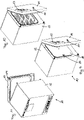
- Figures 1 to 3 show different perspective views of a first embodiment
- Figures 9 to 11 show different perspective views of a second embodiment of a laboratory cabinet 10, which can be designed, for example, as a cold cabinet, warming cabinet, drying cabinet or incubator.
- the statements below apply to both exemplary embodiments, unless expressly stated otherwise.
- the laboratory cabinet 10 has a housing 12 with an outer door 14 which encloses an interior space.
- the housing 12 can have a bottom, a top, two opposite side walls and a back wall, wherein an opening opposite the back wall can be closed by the outer door 14 .
- the outer door 14 can be closed via an outer door lock, which can be actuated by a handle 17 .
- the outer door lock secures the outer door 14 against accidental pivoting.
- An additional locking mechanism can be provided which prevents unlocking of the outer door lock.
- the housing 12 can be double-walled for better thermal insulation and in particular can have an inner tank.
- the laboratory cabinet 10 has at least one inner door 18, which closes an opening in the interior facing the outer door 14 in order to prevent or reduce an exchange of air between the interior and the environment when the outer door 14 is opened.
- the inner door 18 has an inner door lock 20 which secures the inner door 18 against pivoting in a closed position.
- the inner door 18 can have a locking mechanism which prevents the inner door latch 20 from being opened.
- the inner door 18 can be made at least in sections or completely from a transparent material, for example glass.
- the interior is subdivided into several compartments, each of which is closed by a separate interior door 18, so that only one of the interior doors 18 has to be opened when sample material is stored in the laboratory cabinet, in particular in one of the compartments, or removed from the Laboratory cabinet 10 is to be removed, but the climatic conditions in the other sub-rooms are disturbed as little as possible.
- a control panel 13 can be arranged on the outside of the housing 12, with which in particular the climatic conditions in the interior of the laboratory cabinet 10, for example the temperature or the humidity, can be set.
- laboratory cabinet 10 can also have two or more outer doors 14 .
- the Figures 4 to 8 show various detailed views of the inner door lock 20 in the Figures 1 to 3
- the Figures 12 to 16 show various detailed views of the inner door lock 20 in the Figures 9 to 11 illustrated laboratory cabinet 10.
- the laboratory cabinet 10 has adjustable means 20, the inner door 18 being openable together with the outer door 14 or independently of the outer door 14 depending on the position of the means 20, the means 20 being inaccessible when the outer door 14 is closed.
- the means 20 can have a bolt 21 which can be switched between an open position (cf. figure 5 and figure 13 ) and a closed position (cf. 4 and figure 12 ) is adjustable.
- the bolt engages behind a bracket 22 in the closed position and is disengaged from the bracket 22 in the open position.
- the bracket 22 can be fastened on both sides (cf. Figures 4 to 6 ) or fastened on one side and open on one side (cf. Figures 12 to 14 ) or be pivotable.
- the bolt 21 is arranged in particular on the inner door 18
- the bracket 22 is arranged on the housing 12 , in particular an end face of one of the side walls of the housing 12 facing the outer door 14 . With this arrangement, the bolt 21 and the shackle 22 are covered by the outer door 14 when the outer door 14 is closed, so that the means 20 are inaccessible when the outer door 14 is closed.
- the bolt 21 is designed as a rotating bolt.
- the means 20 preferably simultaneously represent an inner door lock, which secures the inner door 18 against pivoting relative to the housing 12 in a closed position and allows the inner door 18 to pivot relative to the housing 12 in an open position.
- a detachable driver is arranged between the outer door 14 and the inner door 18 , the driver being designed as at least one permanent magnet 26 .
- the permanent magnet 26 can be arranged on the inner door 18 or the outer door 14 and is arranged on the inner door 18, in particular on the bolt 21, in the present exemplary embodiment. Since the inner door lock 20 is almost in contact with the outer door 14 when the outer door 14 is closed or can advantageously also lie in a recess on the inside of the outer door 14, and the inside of the outer door 14 is also made of a magnetizable material or alternatively on the inside of the A magnetizable element is arranged on the outer door 14, the inner door 18 is magnetically attracted to the outer door 14 and taken along when the outer door 14 is opened. In particular, the magnetic coupling between the inner door 18 and the outer door 14 can compensate for the relative movement between the inner door 18 and the outer door 14 by the permanent magnet 41 sliding over the inner surface of the outer door 14 .
- the inner door 18 is also closed when the outer door 14 is closed, but when the outer door 14 is opened, the inner door 18 is also closed at the same time due to the magnetic coupling between the inner door 18 and the outer door 14 entrained, so that the inner door 18 is opened together with the outer door 14.
Landscapes
- Engineering & Computer Science (AREA)
- Chemical & Material Sciences (AREA)
- Mechanical Engineering (AREA)
- Health & Medical Sciences (AREA)
- Physics & Mathematics (AREA)
- Life Sciences & Earth Sciences (AREA)
- Zoology (AREA)
- Organic Chemistry (AREA)
- Bioinformatics & Cheminformatics (AREA)
- Wood Science & Technology (AREA)
- General Engineering & Computer Science (AREA)
- Chemical Kinetics & Catalysis (AREA)
- Clinical Laboratory Science (AREA)
- Thermal Sciences (AREA)
- Biomedical Technology (AREA)
- Sustainable Development (AREA)
- Microbiology (AREA)
- Biotechnology (AREA)
- Biochemistry (AREA)
- Analytical Chemistry (AREA)
- General Health & Medical Sciences (AREA)
- Genetics & Genomics (AREA)
- Electromagnetism (AREA)
- Combustion & Propulsion (AREA)
- Refrigerator Housings (AREA)
- Securing Of Glass Panes Or The Like (AREA)
Description
- Die Erfindung betrifft einen Laborschrank . Bekannt sind Laborschränke mit einem wenigstens eine Außentür aufweisenden Gehäuse, welches wenigstens einen Innenraum aufweist. Oft weisen derartige Laborschränke Vorrichtungen auf, mit welchen im Innenraum eine definierte Temperatur und/oder definierte Klimabedingungen, beispielsweise eine definierte Feuchte, einstellbar sind. Beispielsweise sind Kälteschränke, Wärmeschränke, Trockenschränke oder Brutschränke bekannt. Um zu verhindern, dass beim Öffnen der Außentür die klimatischen Bedingungen im Innenraum gestört werden, ist es bekannt, den Innenraum durch eine Innentür zu verschließen. Die Außentüre dient im Wesentlichen der Dämmung zwischen den Innenraum des Laborschranks und der Umgebung. Die Innentür verhindert den Luftaustausch des Innenraums mit der Umgebung beim Öffnen der Außentüre. Die Innentür kann aus transparentem Material gefertigt sein, was es ermöglicht, bei geöffneter Außentür einen Blick in den Innenraum zu werfen, ohne die klimatischen Bedingungen im Innenraum zu stören.
- Bei den bekannten Laborschränken ist es erforderlich, dass ein Benutzer zunächst die Außentür des Laborschranks öffnet und anschließend mit einem zweiten Handgriff die Innentür öffnen kann.
-
US 2013 026 900 A1 beschreibt einen Kühlschrank mit einem wenigstens eine Außentür aufweisenden Gehäuse, welches wenigstens einen Innenraum aufweist, der durch eine Innentür verschließbar ist. Die Innentür des Kühlschranks umfasst eine Verriegelungsvorrichtung, welche mit Rasthaken, die an der Außentür angeordnet sind, zum Verriegeln der Außentür an der Innentür eingreift. Die Verriegelungsvorrichtung ist ein Druck-Zug-Knopf, bei dem die Rasthaken durch einen primären Pressvorgang in der Verriegelungsvorrichtung gefangen werden und der Verriegelungszustand der Rasthaken durch einen sekundären Pressvorgang gelöst wird. Dadurch ist es möglich, durch einen sekundären Pressvorgang die Außentür ohne die Innentür zu öffnen. Die Aufgabe der Erfindung besteht darin, einen Laborschrank dahingehend weiterzubilden, dass er benutzerfreundlicher zu handhaben ist und insbesondere das Öffnen der Innentür vereinfacht wird. - Die Aufgabe der Erfindung wird gelöst durch einen Laborschrank mit den Merkmalen des Patentanspruchs 1.
- Vorteilhafte Ausgestaltungen und Weiterbildungen der Erfindung sind in den abhängigen Ansprüchen angegeben.
- Der erfindungsgemäße Laborschrank, beispielsweise Kälteschrank, Wärmeschrank, Trockenschrank oder Brutschrank, mit einem wenigstens eine Außentür aufweisenden Gehäuse, welches wenigstens einen Innenraum aufweist, der durch eine Innentür verschließbar ist, zeichnet sich dadurch aus, dass der Laborschrank verstellbare Mittel aufweist und in Abhängigkeit von der Stellung der Mittel die Innentür gemeinsam mit der Außentür oder unabhängig von der Außentür öffenbar ist, wobei die Mittel bei geschlossener Außentür unzugänglich sind. Ein derartig ausgestalteter Laborschrank ermöglicht es dem Benutzer, gezielt einzustellen, ob beim Öffnen der Außentür die Innentür mit geöffnet werden soll oder nicht, verhindert aber ein unbefugtes oder unbeabsichtigtes Ändern dieser Einstellung.
- Vorteilhafterweise sind die Mittel als verstellbarer Riegel ausgebildet, welche einfach zu bedienen und wenig störanfällig sind.
- Besonders bevorzugt sind die Mittel als schwenkbarer Riegel ausgebildet, welcher platzsparend angeordnet sein kann.
- Der Riegel kann beispielsweise einen Bügel hintergreifen, wobei der Bügel insbesondere sowohl beidseitig als auch nur einseitig befestigt und damit insbesondere einseitig offen ausgebildet sein kann. Der Bügel kann schwenkbar ausgebildet sein. Eine bevorzugte Weiterbildung der Erfindung sieht vor, dass die Innentür einen Innentürverschluss aufweist und die Mittel durch den Innentürverschluss gebildet sind. Der Innentürverschluss ist derart ausgebildet, dass er in einer geöffneten Position das Verschwenken der Innentür gegen das Gehäuse ermöglicht und in einer geschlossenen Position die Innentür gegen Verschwenken relativ zum Gehäuse sichert. Der Innentürverschluss ist somit verstellbar und ermöglicht in Abhängigkeit von der Stellung der Mittel ein Öffnen der Innentür gemeinsam mit der Außentür oder unabhängig von der Außentür. In dem Fall, dass der Innentürverschluss vor dem Schließen der Außentür geschlossen wird, kann die Außentür unabhängig von der Innentür geöffnet und geschlossen werden. In dem Fall, dass der Innentürverschluss in der geöffneten Position verbleibt, wird durch eine zusätzliche Vorrichtung in Form eines Mitnehmers ein gemeinsames Öffnen der Innentür mit der Außentür ermöglicht.
- Erfindungsgemäß ist zwischen der Außentür und der Innentür ein lösbarer Mitnehmer ausgebildet. Ein Mitnehmer bewirkt dabei eine Kopplung zwischen Außentür und Innentür, die zur Folge hat, dass beim Öffnen der Außentür die Innentür mitgenommen, insbesondere mitgezogen, wird. Ist der Mitnehmer lösbar, kann wahlweise eingestellt werden, ob der Mitnehmer eine Kopplung zwischen der Außentür und der Innentür herstellt oder nicht.
- Erfindungsgemäß ist der Mitnehmer als an einer von Außentür und Innentür angeordneter Permanentmagnet ausgebildet, welcher mit dem anderen von Außentür und Innentür oder mit einem an dem anderen von Außentür und Innentür angeordneten magnetischen Element zusammenwirkt. Durch einen derartig ausgestalteten Mitnehmer ergibt sich eine magnetische Kopplung zwischen Innentür und Außentür, welche vorteilhafterweise auch eine Relativbewegung zwischen Innentür und Außentür beim Schwenken der beiden Türen um unterschiedliche Drehpunkte ermöglicht, da die magnetische Kopplung derart ausgebildet sein kann, dass der Permanentmagnet über das magnetische Element gleitet, um die Relativbewegung zwischen den beiden Türen auszugleichen.
- Eine bevorzugte Ausführungsform der Erfindung sieht vor, dass die Innentür zumindest abschnittsweise aus transparentem Material, insbesondere Glas, gefertigt ist. Dies ermöglicht eine Einsicht in den Innenraum, ohne dass die Innentür geöffnet wird und damit die klimatischen Bedingungen im Innenraum gestört werden.
- Die Erfindung wird anhand der nachfolgenden Figuren ausführlich erläutert. Es zeigen
- Figur 1
- eine perspektivische Ansicht eines ersten Ausführungsbeispiels eines Laborschranks mit geöffneter Außentür,
- Figur 2
- eine perspektivische Ansicht des Laborschranks gemäß
Figur 1 mit geöffneter Außentür und geöffneter Innentür, - Figur 3
- eine weitere perspektivische Ansicht des Laborschranks gemäß
Figur 2 , - Figur 4
- eine vergrößerte Darstellung des Innentürverschlusses des Laborschranks gemäß
Figur 1 mit dem Innentürverschluss in einer geschlossenen Position, - Figur 5
- eine vergrößerte Darstellung des Innentürverschlusses des Laborschranks gemäß
Figur 1 mit dem Innentürverschluss in einer geöffneten Position, - Figur 6
- eine perspektivische Ansicht des Innentürverschlusses gemäß
Figur 4 ; - Figur 7
- eine Draufsicht auf den Innentürverschluss gemäß Figur 4,
- Figur 8
- einen Längsschnitt entlang der Linie A-A durch den Innentürverschluss gemäß
Figur 7 - Figur 9
- eine perspektivische Ansicht eines zweiten Ausführungsbeispiels eines Laborschranks mit geöffneter Außentür,
- Figur 10
- eine perspektivische Ansicht des Laborschranks gemäß
Figur 9 mit geöffneter Außentür und geöffneter Innentür, - Figur 11
- eine weitere perspektivische Ansicht des Laborschranks gemäß
Figur 10 , - Figur 12
- eine vergrößerte Darstellung des Innentürverschlusses des Laborschranks gemäß
Figur 9 mit dem Innentürverschluss in einer geschlossenen Position, - Figur 13
- eine vergrößerte Darstellung des Innentürverschlusses des Laborschranks gemäß
Figur 9 mit dem Innentürverschluss in einer geöffneten Position, - Figur 14
- eine perspektivische Ansicht des Innentürverschlusses gemäß
Figur 12 , - Figur 15
- eine Draufsicht auf den Innentürverschluss gemäß Figur 12,
- Figur 16
- einen Längsschnitt entlang der Linie A-A durch den Innentürverschluss gemäß
Figur 15 . - Die
Figuren 1 bis 3 zeigen verschiedene perspektivische Ansichten eines ersten AusführungsbeispielsFiguren 9 bis 11 zeigen verschiedene perspektivische Ansichten eines zweiten Ausführungsbeispiels eines Laborschranks 10, welcher beispielsweise als Kälteschrank, Wärmeschrank, Trockenschrank oder Brutschrank ausgebildet sein kann. Die nachstehenden Ausführungen gelten für beide Ausführungsbeispiele, soweit nicht ausdrücklich anders angegeben. - Der Laborschrank 10 weist ein Gehäuse 12 mit einer Außentür 14 auf, welches einen Innenraum umschließt. Das Gehäuse 12 kann eine Bodenseite, eine Deckseite, zwei gegenüberliegende Seitenwände und eine Rückwand aufweisen, wobei eine der Rückwand gegenüberliegende Öffnung durch die Außentür 14 verschlossen werden kann. Die Außentür 14 kann über einen Außentürverschluss geschlossen werden, welcher durch einen Handgriff 17 betätigt werden kann. Der Außentürverschluss sichert die Außentür 14 gegen zufälliges Verschwenken. Es kann ein zusätzlicher Sperrmechanismus vorgesehen sein, welcher das Entriegeln des Außentürverschlusses verhindert.
- Das Gehäuse 12 kann zur besseren Wärmedämmung doppelwandig ausgebildet sein und insbesondere einen Innenkessel aufweisen. Der Laborschrank 10 weist wenigstens eine Innentür 18 auf, welche eine zur Außentür 14 weisende Öffnung des Innenraums verschließt, um einen Luftaustausch des Innenraums mit der Umgebung zu unterbinden oder zu verringern, wenn die Außentür 14 geöffnet wird.
- Die Innentür 18 weist einen Innentürverschluss 20 auf, welcher die Innentür 18 in einer geschlossenen Position gegen Verschwenken sichert. Zusätzlich kann die Innentür 18 einen Sperrmechanismus aufweisen, welcher verhindert, dass der Innentürverschluss 20 geöffnet werden kann.
- Die Innentür 18 kann zumindest abschnittsweise oder auch vollständig aus einem transparenten Material, beispielsweise Glas, gefertigt sein.
- Es ist möglich, dass der Innenraum in mehrere Teilräume unterteilt ist, welche jeweils durch eine separate Innentür 18 verschlossen sind, so dass lediglich eine der Innentüren 18 geöffnet werden muss, wenn Probengut in den Laborschrank, insbesondere in einen der Teilräume, eingelagert oder aus dem Laborschrank 10 entnommen werden soll, dabei aber die klimatischen Bedingungen in den anderen Teilräumen möglichst wenig gestört werden.
- An der Außenseite des Gehäuses 12 kann ein Bedienfeld 13 angeordnet sein, mit welchem insbesondere die klimatischen Bedingungen im Innenraum des Laborschranks 10, beispielsweise die Temperatur oder die Feuchte, eingestellt werden können.
- Grundsätzlich ist es selbstverständlich möglich, dass der Laborschrank 10 auch zwei oder mehrere Außentüren 14 aufweisen kann.
- Die
Figuren 4 bis 8 zeigen verschiedene Detailansichten des Innentürverschlusses 20 des in denFiguren 1 bis 3 , dieFiguren 12 bis 16 zeigen verschiedene Detailansichten des Innentürverschlusses 20 des in denFiguren 9 bis 11 dargestellten Laborschranks 10. - Der Laborschrank 10 weist verstellbare Mittel 20 auf, wobei in Abhängigkeit von der Stellung der Mittel 20 die Innentür 18 gemeinsam mit der Außentür 14 oder unabhängig von der Außentür 14 öffenbar ist, wobei die Mittel 20 bei geschlossener Außentür 14 unzugänglich sind.
- Die Mittel 20 können einen Riegel 21 aufweisen, welcher zwischen einer geöffneten Position (vgl.
Figur 5 undFigur 13 ) und einer geschlossenen Position (vgl.Fig. 4 undFigur 12 ) verstellbar ist. Dazu greift der Riegel in der geschlossenen Position hinter einen Bügel 22 und ist in der geöffneten Position außer Eingriff mit dem Bügel 22. Der Bügel 22 kann dabei beidseitig befestigt (vgl.Figuren 4 bis 6 ) oder einseitig befestigt und einseitig offen (vgl.Figuren 12 bis 14 ) oder auch schwenkbar ausgebildet sein. Der Riegel 21 ist insbesondere an der Innentür 18 angeordnet, während der Bügel 22 an dem Gehäuse 12, insbesondere einer der Außentür 14 zugewandten Stirnseite einer der Seitenwände des Gehäuses 12, angeordnet ist. Durch diese Anordnung sind der Riegel 21 und der Bügel 22 durch die Außentür 14 abgedeckt, wenn die Außentür 14 geschlossen ist, so dass die Mittel 20 bei geschlossener Außentür 14 unzugänglich sind. Insbesondere ist der Riegel 21 als Drehriegel ausgebildet. - Es besteht die Möglichkeit, den Riegel 21 in der geöffneten Position durch einen Rastmechanismus zu sichern, um ein unbeabsichtigtes Verstellen des Riegels 21 zu erschweren.
- Die Mittel 20 stellen vorzugsweise gleichzeitig einen Innentürverschluss dar, welcher die Innentür 18 in einer geschlossenen Position gegen Verschwenken relativ zum Gehäuse 12 sichert und in einer geöffneten Position das Verschwenken der Innentür 18 gegen das Gehäuse 12 erlaubt.
- Zwischen der Außentür 14 und der Innentür 18 ist ein lösbarer Mitnehmer angeordnet, wobei der Mitnehmer als wenigstens ein Permanentmagnet 26 ausgebildet ist. Der Permanentmagnet 26 kann an der Innentür 18 oder der Außentür 14 angeordnet sein und ist im vorliegenden Ausführungsbeispiel an der Innentür 18, insbesondere an dem Riegel 21, angeordnet. Da der Innentürverschluss 20 bei geschlossener Außentür 14 an der Außentür 14 nahezu anliegt oder vorteilhafterweise auch in einer Mulde auf der Innenseite der Außentür 14 zu liegen kommen kann, und zudem die Innenseite der Außentür 14 aus einem magnetisierbaren Material gefertigt ist oder alternativ an der Innenseite der Außentür 14 ein magnetisierbares Element angeordnet ist, wird die Innentür 18 von der Außentür 14 magnetisch angezogen und bei Öffnen der Außentür 14 mitgenommen. Insbesondere kann die magnetische Kopplung zwischen der Innentür 18 und der Außentür 14 die Relativbewegung zwischen Innentür 18 und der Außentür 14 ausgleichen, indem der Permanentmagnet 41 über die Innenfläche der Außentür 14 gleitet.
- Zur Bedienung der Türen 14, 18 bestehen unter anderem folgende Möglichkeiten: Ist vor dem Verschließen der Außentür 14 die Innentür 18 mittels der Mittel 20 verriegelt worden derart, dass der Riegel 21 in die geschlossene Position überführt wurde, kann ein Öffnen der Außentür 14 unabhängig von der Innentür 18 erfolgen, da beim Öffnen der Außentür 14 die magnetische Kopplung zwischen Innentür 18 und Außentür 14 gelöst wird, da die Innentür 18 durch den Riegel 21 in der geschlossenen Position gehalten wird. Ist vor dem Verschließen der Außentür 14 der Riegel 21 in die geöffnete Position überführt worden, wird beim Verschließen der Außentür 14 auch die Innentür 18 mit geschlossenen, beim Öffnen der Außentür 14 wird die Innentür 18 aber auch gleichzeitig aufgrund der magnetischen Kopplung zwischen der Innentür 18 und der Außentür 14 mitgenommen, so dass die Innentür 18 gemeinsam mit der Außentür 14 geöffnet wird.
-
- 10
- Laborschrank
- 13
- Bedienfeld
- 12
- Gehäuse
- 14
- Außentür
- 16
- Außentürverschluss
- 17
- Handgriff
- 18
- Innentür
- 20
- Mittel
- 21
- Riegel
- 22
- Bügel
- 26
- Permanentmagnet
Claims (5)
- Laborschrank (10), beispielsweise Kälteschrank, Wärmeschrank, Trockenschrank oder Brutschrank, mit einem wenigstens eine Außentür (14) aufweisenden Gehäuse (12), welches wenigstens einen Innenraum aufweist, der durch eine Innentür (18) verschließbar ist,wobei der Laborschrank (10)von dem Benutzer verstellbare Mittel (20) aufweist, die zwischen einer geöffneten Position und einen geschlossenen Position vor dem Verschließen der Außentür (14) verstellbar sind und in Abhängigkeit von der Stellung der Mittel (20) die Innentür (18) gemeinsam mit der Außentür (14) oder unabhängig von der Außentür (14) öffenbar ist, wobei die Mittel (20) bei geschlossener Außentür (14) unzugänglich sind, wobei zwischen der Außentür (14) und der Innentür (18) ein lösbarer Mitnehmer ausgebildet ist und wobei der Mitnehmer als an einer von Außentür (14) und Innentür (18) angeordneter Permanentmagnet (26) ausgebildet ist, welcher mit dem anderen von Außentür (14) und Innentür (18) oder mit einem an dem anderen von Außentür (14) und Innentür (18) angeordnetem magnetisierbaren Element zusammenwirkt.
- Laborschrank nach Anspruch 1,
dadurch gekennzeichnet, dass die Mittel (20) als verstellbarer Riegel (21) ausgebildet sind. - Laborschrank nach einem der vorhergehenden Ansprüche,
dadurch gekennzeichnet, dass die Mittel als schwenkbarer Riegel (21) ausgebildet sind. - Laborschrank nach einem der vorhergehenden Ansprüche,
dadurch gekennzeichnet, dass die Innentür (18) einen Innentürverschluss aufweist und die Mittel (20) durch den Innentürverschluss gebildet sind. - Laborschrank nach einem der vorhergehenden Ansprüche,
dadurch gekennzeichnet, dass die Innentür (18) zumindest abschnittsweise aus transparentem Material, insbesondere Glas, gefertigt ist.
Priority Applications (3)
| Application Number | Priority Date | Filing Date | Title |
|---|---|---|---|
| RU2018115704A RU2700760C1 (ru) | 2017-04-28 | 2018-04-26 | Лабораторный шкаф |
| CN201810390177.5A CN108786936B (zh) | 2017-04-28 | 2018-04-27 | 实验室柜 |
| US15/965,443 US10427149B2 (en) | 2017-04-28 | 2018-04-27 | Laboratory cabinet |
Applications Claiming Priority (1)
| Application Number | Priority Date | Filing Date | Title |
|---|---|---|---|
| DE102017109262.5A DE102017109262A1 (de) | 2017-04-28 | 2017-04-28 | Laborschrank |
Publications (2)
| Publication Number | Publication Date |
|---|---|
| EP3396091A1 EP3396091A1 (de) | 2018-10-31 |
| EP3396091B1 true EP3396091B1 (de) | 2022-08-17 |
Family
ID=61256535
Family Applications (1)
| Application Number | Title | Priority Date | Filing Date |
|---|---|---|---|
| EP18000153.9A Active EP3396091B1 (de) | 2017-04-28 | 2018-02-16 | Laborschrank |
Country Status (6)
| Country | Link |
|---|---|
| US (1) | US10427149B2 (de) |
| EP (1) | EP3396091B1 (de) |
| CN (1) | CN108786936B (de) |
| DE (1) | DE102017109262A1 (de) |
| PL (1) | PL3396091T3 (de) |
| RU (1) | RU2700760C1 (de) |
Families Citing this family (6)
| Publication number | Priority date | Publication date | Assignee | Title |
|---|---|---|---|---|
| US10188098B2 (en) * | 2009-05-12 | 2019-01-29 | Reflect Scientific Inc. | Extremely fast freezing, low-temperature blast freezer |
| EP3539420A1 (de) * | 2018-03-16 | 2019-09-18 | Eppendorf AG | Laborschrankvorrichtung zum lagern von laborproben mit magnetverschluss |
| USD873414S1 (en) * | 2018-10-12 | 2020-01-21 | Binder Gmbh | Laboratory cabinet |
| EP3899386B1 (de) * | 2018-12-21 | 2023-06-07 | Electrolux Appliances Aktiebolag | Haushaltsgerät mit umkehrbarer tür |
| TWI705180B (zh) * | 2019-11-11 | 2020-09-21 | 寬豐工業股份有限公司 | 具雙重鎖機制之容置櫃 |
| US11649654B2 (en) * | 2020-10-12 | 2023-05-16 | Cytiva Us Llc | Tank with door locking mechanism |
Citations (1)
| Publication number | Priority date | Publication date | Assignee | Title |
|---|---|---|---|---|
| WO2015072793A1 (en) * | 2013-11-18 | 2015-05-21 | Samsung Electronics Co., Ltd. | Refrigerator |
Family Cites Families (16)
| Publication number | Priority date | Publication date | Assignee | Title |
|---|---|---|---|---|
| SU650583A1 (ru) * | 1977-04-14 | 1979-03-05 | Всесоюзный Ордена Трудового Красного Знамени Научно-Исследовательский И Технологический Институт Птицеводства | Инкубатор |
| CA1126785A (en) * | 1978-10-13 | 1982-06-29 | Jose Massana Canals | Personal security door arrangement |
| FR2596094B1 (fr) * | 1986-03-18 | 1991-12-06 | Jouan | Systeme de detection de la fermeture imparfaite des portes d'une enceinte a portes multiples |
| US6128119A (en) | 1997-01-10 | 2000-10-03 | Asahi Kogaku Kogyo Kabushiki Kaisha | Beam shaping optical system |
| DE19803601C1 (de) * | 1998-01-30 | 1999-09-09 | Kendro Lab Prod Gmbh | Verfahren zur Verschlußkontrolle für Brut- und Trockenschränke sowie Brut- oder Trockenschrank |
| US6867685B1 (en) * | 1999-05-10 | 2005-03-15 | Star Lock Systems, Inc. | Electro-mechanical lock assembly |
| GB2426569B (en) * | 2003-03-28 | 2007-09-19 | Lg Electronics Inc | Refrigerator |
| CN201100079Y (zh) * | 2007-09-20 | 2008-08-13 | 汪旻 | 防盗双层门 |
| KR20100122155A (ko) * | 2009-05-12 | 2010-11-22 | 엘지전자 주식회사 | 냉장고 |
| RU93460U1 (ru) | 2009-12-04 | 2010-04-27 | Юрий Васильевич Бабичев | Бесшатунный двигатель внутреннего сгорания с вращающимся поршнем |
| CN102116554A (zh) * | 2010-01-04 | 2011-07-06 | Lg电子株式会社 | 电冰箱 |
| RU95460U1 (ru) * | 2010-03-31 | 2010-07-10 | Владимир Николаевич Терехов | Инкубатор |
| DE102012103629A1 (de) * | 2012-04-25 | 2013-10-31 | Hettich-Oni Gmbh & Co. Kg | Schlepptürbeschlag |
| CN203796008U (zh) * | 2014-03-27 | 2014-08-27 | 信昌机械厂股份有限公司 | 汽车门锁的解锁机构 |
| CN104764276A (zh) * | 2015-03-25 | 2015-07-08 | 苏州食行生鲜电子商务有限公司 | 保温防盗双层柜门及保温柜 |
| DE102017109263B4 (de) * | 2017-04-28 | 2019-06-06 | Binder Gmbh | Laborschrank |
-
2017
- 2017-04-28 DE DE102017109262.5A patent/DE102017109262A1/de not_active Ceased
-
2018
- 2018-02-16 EP EP18000153.9A patent/EP3396091B1/de active Active
- 2018-02-16 PL PL18000153.9T patent/PL3396091T3/pl unknown
- 2018-04-26 RU RU2018115704A patent/RU2700760C1/ru active
- 2018-04-27 CN CN201810390177.5A patent/CN108786936B/zh active Active
- 2018-04-27 US US15/965,443 patent/US10427149B2/en active Active
Patent Citations (1)
| Publication number | Priority date | Publication date | Assignee | Title |
|---|---|---|---|---|
| WO2015072793A1 (en) * | 2013-11-18 | 2015-05-21 | Samsung Electronics Co., Ltd. | Refrigerator |
Also Published As
| Publication number | Publication date |
|---|---|
| RU2700760C1 (ru) | 2019-09-19 |
| US10427149B2 (en) | 2019-10-01 |
| DE102017109262A1 (de) | 2018-10-31 |
| CN108786936A (zh) | 2018-11-13 |
| PL3396091T3 (pl) | 2022-12-19 |
| US20180311659A1 (en) | 2018-11-01 |
| CN108786936B (zh) | 2021-04-09 |
| EP3396091A1 (de) | 2018-10-31 |
Similar Documents
| Publication | Publication Date | Title |
|---|---|---|
| EP3396092B1 (de) | Laborschrank | |
| EP3396091A1 (de) | Laborschrank | |
| DE102018203271A1 (de) | Haushaltskältegerät mit einer Schublade und Verfahren zum Herstellen des Haushaltskältegerätes | |
| DE3300575C2 (de) | Kontrolleinrichtung für Hotelkühlschränke und andere verschließbare Selbstbedienungsgeräte | |
| EP2463460B1 (de) | Elektrisches Türschloss mit Tür-Stopp-Mechanismus | |
| EP2441905B1 (de) | Schloss | |
| EP1507124A2 (de) | Elektrisches Gerät mit drehbarem Griff | |
| WO2018172087A1 (de) | Haushaltskältegerät mit einem türblatt und einem türabsteller | |
| DE102020209247A1 (de) | Tür und Haushaltsgargerät | |
| DE2826082A1 (de) | Verschlussgriff | |
| EP2556313A2 (de) | Kältegerät mit zwischentür zur verringerung des temperaturausgleichs | |
| DE102010001587B4 (de) | Hausgerätvorrichtung | |
| DE102008044133A1 (de) | Kältegerät | |
| DE29917091U1 (de) | Griffhebelverschluß zur Montage in einem rechteckigen Durchbruch in einer dünnen Wand, wie Blechschranktür | |
| DE102012015412A1 (de) | Kühl- und/oder Gefriergerät | |
| DE102020122794A1 (de) | Türvorrichtung für eine Nische zum Aufnehmen eines Küchengeräts und Küchenmöbel | |
| EP2998475B1 (de) | Tageshebel für ein passivflügelschloss | |
| DE102021122832A1 (de) | Schließanordnung für eine Klappe eines Fahrzeugs | |
| DE3316621C2 (de) | ||
| DE112007002208T5 (de) | Verriegelungsvorrichtung | |
| DE102010015464A1 (de) | Schwenkhebelverschluss mit einem von dessen Mulde abragenden Griffhebel | |
| DE102020104890B4 (de) | Außentüre eines Nutzfahrzeugs sowie Nutzfahrzeugaufbau und Nutzfahrzeug mit einer solchen Außentüre | |
| DE2518819A1 (de) | Vorrichtung zum loesbaren verriegeln und abschliessen der tuer von kuehlund tiefkuehlraeumen | |
| DE602004007944T2 (de) | Innenverriegelungsvorrichtung für ein kraftfahrzeug, in dem der innere türverriegelungsknopf freigegeben ist | |
| WO2012025558A2 (de) | Kältegerät mit einer traverse |
Legal Events
| Date | Code | Title | Description |
|---|---|---|---|
| PUAI | Public reference made under article 153(3) epc to a published international application that has entered the european phase |
Free format text: ORIGINAL CODE: 0009012 |
|
| STAA | Information on the status of an ep patent application or granted ep patent |
Free format text: STATUS: THE APPLICATION HAS BEEN PUBLISHED |
|
| AK | Designated contracting states |
Kind code of ref document: A1 Designated state(s): AL AT BE BG CH CY CZ DE DK EE ES FI FR GB GR HR HU IE IS IT LI LT LU LV MC MK MT NL NO PL PT RO RS SE SI SK SM TR |
|
| AX | Request for extension of the european patent |
Extension state: BA ME |
|
| STAA | Information on the status of an ep patent application or granted ep patent |
Free format text: STATUS: REQUEST FOR EXAMINATION WAS MADE |
|
| 17P | Request for examination filed |
Effective date: 20190122 |
|
| RBV | Designated contracting states (corrected) |
Designated state(s): AL AT BE BG CH CY CZ DE DK EE ES FI FR GB GR HR HU IE IS IT LI LT LU LV MC MK MT NL NO PL PT RO RS SE SI SK SM TR |
|
| STAA | Information on the status of an ep patent application or granted ep patent |
Free format text: STATUS: EXAMINATION IS IN PROGRESS |
|
| 17Q | First examination report despatched |
Effective date: 20200421 |
|
| GRAP | Despatch of communication of intention to grant a patent |
Free format text: ORIGINAL CODE: EPIDOSNIGR1 |
|
| STAA | Information on the status of an ep patent application or granted ep patent |
Free format text: STATUS: GRANT OF PATENT IS INTENDED |
|
| INTG | Intention to grant announced |
Effective date: 20220317 |
|
| GRAS | Grant fee paid |
Free format text: ORIGINAL CODE: EPIDOSNIGR3 |
|
| GRAA | (expected) grant |
Free format text: ORIGINAL CODE: 0009210 |
|
| STAA | Information on the status of an ep patent application or granted ep patent |
Free format text: STATUS: THE PATENT HAS BEEN GRANTED |
|
| AK | Designated contracting states |
Kind code of ref document: B1 Designated state(s): AL AT BE BG CH CY CZ DE DK EE ES FI FR GB GR HR HU IE IS IT LI LT LU LV MC MK MT NL NO PL PT RO RS SE SI SK SM TR |
|
| REG | Reference to a national code |
Ref country code: CH Ref legal event code: EP |
|
| REG | Reference to a national code |
Ref country code: DE Ref legal event code: R096 Ref document number: 502018010386 Country of ref document: DE |
|
| REG | Reference to a national code |
Ref country code: IE Ref legal event code: FG4D Free format text: LANGUAGE OF EP DOCUMENT: GERMAN |
|
| REG | Reference to a national code |
Ref country code: AT Ref legal event code: REF Ref document number: 1512290 Country of ref document: AT Kind code of ref document: T Effective date: 20220915 |
|
| REG | Reference to a national code |
Ref country code: NL Ref legal event code: MP Effective date: 20220817 |
|
| REG | Reference to a national code |
Ref country code: LT Ref legal event code: MG9D |
|
| PG25 | Lapsed in a contracting state [announced via postgrant information from national office to epo] |
Ref country code: SE Free format text: LAPSE BECAUSE OF FAILURE TO SUBMIT A TRANSLATION OF THE DESCRIPTION OR TO PAY THE FEE WITHIN THE PRESCRIBED TIME-LIMIT Effective date: 20220817 Ref country code: RS Free format text: LAPSE BECAUSE OF FAILURE TO SUBMIT A TRANSLATION OF THE DESCRIPTION OR TO PAY THE FEE WITHIN THE PRESCRIBED TIME-LIMIT Effective date: 20220817 Ref country code: PT Free format text: LAPSE BECAUSE OF FAILURE TO SUBMIT A TRANSLATION OF THE DESCRIPTION OR TO PAY THE FEE WITHIN THE PRESCRIBED TIME-LIMIT Effective date: 20221219 Ref country code: NO Free format text: LAPSE BECAUSE OF FAILURE TO SUBMIT A TRANSLATION OF THE DESCRIPTION OR TO PAY THE FEE WITHIN THE PRESCRIBED TIME-LIMIT Effective date: 20221117 Ref country code: NL Free format text: LAPSE BECAUSE OF FAILURE TO SUBMIT A TRANSLATION OF THE DESCRIPTION OR TO PAY THE FEE WITHIN THE PRESCRIBED TIME-LIMIT Effective date: 20220817 Ref country code: LV Free format text: LAPSE BECAUSE OF FAILURE TO SUBMIT A TRANSLATION OF THE DESCRIPTION OR TO PAY THE FEE WITHIN THE PRESCRIBED TIME-LIMIT Effective date: 20220817 Ref country code: LT Free format text: LAPSE BECAUSE OF FAILURE TO SUBMIT A TRANSLATION OF THE DESCRIPTION OR TO PAY THE FEE WITHIN THE PRESCRIBED TIME-LIMIT Effective date: 20220817 Ref country code: FI Free format text: LAPSE BECAUSE OF FAILURE TO SUBMIT A TRANSLATION OF THE DESCRIPTION OR TO PAY THE FEE WITHIN THE PRESCRIBED TIME-LIMIT Effective date: 20220817 |
|
| PG25 | Lapsed in a contracting state [announced via postgrant information from national office to epo] |
Ref country code: IS Free format text: LAPSE BECAUSE OF FAILURE TO SUBMIT A TRANSLATION OF THE DESCRIPTION OR TO PAY THE FEE WITHIN THE PRESCRIBED TIME-LIMIT Effective date: 20221217 Ref country code: HR Free format text: LAPSE BECAUSE OF FAILURE TO SUBMIT A TRANSLATION OF THE DESCRIPTION OR TO PAY THE FEE WITHIN THE PRESCRIBED TIME-LIMIT Effective date: 20220817 Ref country code: GR Free format text: LAPSE BECAUSE OF FAILURE TO SUBMIT A TRANSLATION OF THE DESCRIPTION OR TO PAY THE FEE WITHIN THE PRESCRIBED TIME-LIMIT Effective date: 20221118 |
|
| PG25 | Lapsed in a contracting state [announced via postgrant information from national office to epo] |
Ref country code: SM Free format text: LAPSE BECAUSE OF FAILURE TO SUBMIT A TRANSLATION OF THE DESCRIPTION OR TO PAY THE FEE WITHIN THE PRESCRIBED TIME-LIMIT Effective date: 20220817 Ref country code: RO Free format text: LAPSE BECAUSE OF FAILURE TO SUBMIT A TRANSLATION OF THE DESCRIPTION OR TO PAY THE FEE WITHIN THE PRESCRIBED TIME-LIMIT Effective date: 20220817 Ref country code: ES Free format text: LAPSE BECAUSE OF FAILURE TO SUBMIT A TRANSLATION OF THE DESCRIPTION OR TO PAY THE FEE WITHIN THE PRESCRIBED TIME-LIMIT Effective date: 20220817 Ref country code: DK Free format text: LAPSE BECAUSE OF FAILURE TO SUBMIT A TRANSLATION OF THE DESCRIPTION OR TO PAY THE FEE WITHIN THE PRESCRIBED TIME-LIMIT Effective date: 20220817 Ref country code: CZ Free format text: LAPSE BECAUSE OF FAILURE TO SUBMIT A TRANSLATION OF THE DESCRIPTION OR TO PAY THE FEE WITHIN THE PRESCRIBED TIME-LIMIT Effective date: 20220817 |
|
| REG | Reference to a national code |
Ref country code: DE Ref legal event code: R097 Ref document number: 502018010386 Country of ref document: DE |
|
| PG25 | Lapsed in a contracting state [announced via postgrant information from national office to epo] |
Ref country code: SK Free format text: LAPSE BECAUSE OF FAILURE TO SUBMIT A TRANSLATION OF THE DESCRIPTION OR TO PAY THE FEE WITHIN THE PRESCRIBED TIME-LIMIT Effective date: 20220817 Ref country code: EE Free format text: LAPSE BECAUSE OF FAILURE TO SUBMIT A TRANSLATION OF THE DESCRIPTION OR TO PAY THE FEE WITHIN THE PRESCRIBED TIME-LIMIT Effective date: 20220817 |
|
| P01 | Opt-out of the competence of the unified patent court (upc) registered |
Effective date: 20230421 |
|
| PLBE | No opposition filed within time limit |
Free format text: ORIGINAL CODE: 0009261 |
|
| STAA | Information on the status of an ep patent application or granted ep patent |
Free format text: STATUS: NO OPPOSITION FILED WITHIN TIME LIMIT |
|
| PG25 | Lapsed in a contracting state [announced via postgrant information from national office to epo] |
Ref country code: AL Free format text: LAPSE BECAUSE OF FAILURE TO SUBMIT A TRANSLATION OF THE DESCRIPTION OR TO PAY THE FEE WITHIN THE PRESCRIBED TIME-LIMIT Effective date: 20220817 |
|
| 26N | No opposition filed |
Effective date: 20230519 |
|
| PG25 | Lapsed in a contracting state [announced via postgrant information from national office to epo] |
Ref country code: SI Free format text: LAPSE BECAUSE OF FAILURE TO SUBMIT A TRANSLATION OF THE DESCRIPTION OR TO PAY THE FEE WITHIN THE PRESCRIBED TIME-LIMIT Effective date: 20220817 |
|
| PG25 | Lapsed in a contracting state [announced via postgrant information from national office to epo] |
Ref country code: MC Free format text: LAPSE BECAUSE OF FAILURE TO SUBMIT A TRANSLATION OF THE DESCRIPTION OR TO PAY THE FEE WITHIN THE PRESCRIBED TIME-LIMIT Effective date: 20220817 |
|
| REG | Reference to a national code |
Ref country code: BE Ref legal event code: MM Effective date: 20230228 |
|
| PG25 | Lapsed in a contracting state [announced via postgrant information from national office to epo] |
Ref country code: LU Free format text: LAPSE BECAUSE OF NON-PAYMENT OF DUE FEES Effective date: 20230216 |
|
| REG | Reference to a national code |
Ref country code: IE Ref legal event code: MM4A |
|
| PG25 | Lapsed in a contracting state [announced via postgrant information from national office to epo] |
Ref country code: IE Free format text: LAPSE BECAUSE OF NON-PAYMENT OF DUE FEES Effective date: 20230216 |
|
| PG25 | Lapsed in a contracting state [announced via postgrant information from national office to epo] |
Ref country code: BE Free format text: LAPSE BECAUSE OF NON-PAYMENT OF DUE FEES Effective date: 20230228 |
|
| REG | Reference to a national code |
Ref country code: AT Ref legal event code: MM01 Ref document number: 1512290 Country of ref document: AT Kind code of ref document: T Effective date: 20230216 |
|
| PG25 | Lapsed in a contracting state [announced via postgrant information from national office to epo] |
Ref country code: AT Free format text: LAPSE BECAUSE OF NON-PAYMENT OF DUE FEES Effective date: 20230216 |
|
| PG25 | Lapsed in a contracting state [announced via postgrant information from national office to epo] |
Ref country code: AT Free format text: LAPSE BECAUSE OF NON-PAYMENT OF DUE FEES Effective date: 20230216 |
|
| PG25 | Lapsed in a contracting state [announced via postgrant information from national office to epo] |
Ref country code: BG Free format text: LAPSE BECAUSE OF FAILURE TO SUBMIT A TRANSLATION OF THE DESCRIPTION OR TO PAY THE FEE WITHIN THE PRESCRIBED TIME-LIMIT Effective date: 20220817 |
|
| PG25 | Lapsed in a contracting state [announced via postgrant information from national office to epo] |
Ref country code: BG Free format text: LAPSE BECAUSE OF FAILURE TO SUBMIT A TRANSLATION OF THE DESCRIPTION OR TO PAY THE FEE WITHIN THE PRESCRIBED TIME-LIMIT Effective date: 20220817 |
|
| PG25 | Lapsed in a contracting state [announced via postgrant information from national office to epo] |
Ref country code: CY Free format text: LAPSE BECAUSE OF FAILURE TO SUBMIT A TRANSLATION OF THE DESCRIPTION OR TO PAY THE FEE WITHIN THE PRESCRIBED TIME-LIMIT; INVALID AB INITIO Effective date: 20180216 |
|
| PG25 | Lapsed in a contracting state [announced via postgrant information from national office to epo] |
Ref country code: HU Free format text: LAPSE BECAUSE OF FAILURE TO SUBMIT A TRANSLATION OF THE DESCRIPTION OR TO PAY THE FEE WITHIN THE PRESCRIBED TIME-LIMIT; INVALID AB INITIO Effective date: 20180216 |
|
| PG25 | Lapsed in a contracting state [announced via postgrant information from national office to epo] |
Ref country code: TR Free format text: LAPSE BECAUSE OF FAILURE TO SUBMIT A TRANSLATION OF THE DESCRIPTION OR TO PAY THE FEE WITHIN THE PRESCRIBED TIME-LIMIT Effective date: 20220817 |
|
| REG | Reference to a national code |
Ref country code: CH Ref legal event code: U11 Free format text: ST27 STATUS EVENT CODE: U-0-0-U10-U11 (AS PROVIDED BY THE NATIONAL OFFICE) Effective date: 20260301 |
|
| PGFP | Annual fee paid to national office [announced via postgrant information from national office to epo] |
Ref country code: GB Payment date: 20260219 Year of fee payment: 9 |
|
| PGFP | Annual fee paid to national office [announced via postgrant information from national office to epo] |
Ref country code: DE Payment date: 20260323 Year of fee payment: 9 |
|
| PGFP | Annual fee paid to national office [announced via postgrant information from national office to epo] |
Ref country code: IT Payment date: 20260227 Year of fee payment: 9 |
|
| PGFP | Annual fee paid to national office [announced via postgrant information from national office to epo] |
Ref country code: FR Payment date: 20260223 Year of fee payment: 9 |
|
| PGFP | Annual fee paid to national office [announced via postgrant information from national office to epo] |
Ref country code: CH Payment date: 20260301 Year of fee payment: 9 |
|
| PGFP | Annual fee paid to national office [announced via postgrant information from national office to epo] |
Ref country code: PL Payment date: 20260202 Year of fee payment: 9 |